

Page 1

CASSETTE TYPE AIR CONDITIONER
(Cool and Heat)
Type
ACH1800E(1)
ACH2400E(1)
ACH3600G(1)
ACH4400G(1)
CH18ZA
CH24ZA
CH36ZA
CH44ZA
CH18CA
CH24CA
CH36CA
CH44CA
SERVICE
Indoor Unit
ICH1800E
ICH2400E
ICH3600G
ICH4400G
CH18ZA
CH24ZA
CH36ZA
CH44ZA
CH18CA
CH24CA
CH36CA
CH44CA
Outdoor Unit
UBH1800E
UBH2400E
UCH3600G
UCH4400G
CH18ZAX
CH24ZAX
CH36ZAX
CH44ZAX
CH18CAX
CH24CAX
CH36CAX
CH44CAX
Manual
Panel
IFS095G00/01
IFS095G00/01
IFS095G00/01
IFS095G00/01
CH01(02)ZAP
CH01(02)ZAP
CH01(02)ZAP
CH01(02)ZAP
CH01(02)ZAP
CH01(02)ZAP
CH01(02)ZAP
CH01(02)ZAP
AIR CONDITIONER CONTENTS
1. Precautions
2. Product Specifications
3. Operating Instructions
4. Installation
5. Disassembly and Reassembly
6. Troubleshooting
7. Exploded Views and Parts List
8. Block Diagrams
9. PCB Diagrams
10. Schematic Diagrams
11. Wiring Diagrams
Page 2
1. Precautions
dangerous
1. Warning: Prior to repair, disconnect the
power cord from the circuit breaker.
2. Use proper parts: Use only exact replacement
parts. (Also, we recommend replacing parts
rather than repairing them.)
3. Use the proper tools: Use the proper tools
and test equipment, and know how to use
them. Using defective tools or test equipment may cause problems later-intermittent
contact, for example.
4. Power Cord: Prior to repair, check the power
cord and replace it if necessary.
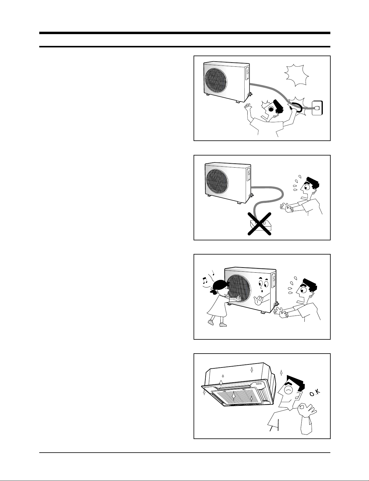
5. Avoid using an extension cord, and avoid
tapping into a power cord. This practice
may result in malfunction or fire.
Fig. 1-1 Avoid Dangerous Contact
6. After completing repairs and reassembly,
check the insulation resistance. Procedure:
Prior to applying power, measure the resistance between the power cord and the
ground terminal. The resistance must be
greater than 30 megohms.
7. Make sure that the grounds are adequate.
8. Make sure that the installation conditions
are satisfactory. Relocate the unit if necessary.
9. Keep children away from the unit while it is
being repaired.
10. Be sure to clean the unit and its surrounding
area.
11. Be sure that the installed conditions are
satisfactory and correct according to the
specifications.
Fig. 1-2 No Tapping and No Extension Cords
Fig. 1-3 No Kids Nearby!
Samsung Electronics
Fig. 1-4 Clean the Unit
1-1
Page 3

MEMO
1-2 Samsung Electronics
Page 4

2. Product Specifications
2-1 Table of Specifications
MODEL
Capacity
Power supply
Power input
Running
current
EER
Indoor
Fan speed
unit
Air
circulation
Noise Level
(Sound
pressure)
Heat
exchanger
Fan
Dimensions
Weight
Panel
Dimensions
Weight
Outdoor
Fan speed
unit
INDOOR UNIT
OUTDOOR UNIT
Cooling
Btu/h
W
Heating
Btu/h
W
Cooling
Heating
Cooling
Heating
Cooling
Heating
H.H
Hi
Med
Low
H.H
Hi
Med
Low
Hi
Med
Low
kW
kW
A
A
W/W
W/W
r.p.m.
r.p.m.
r.p.m.
r.p.m.
3
/min
m
3
/min
m
3
/min
m
3
/min
m
dB(A)
dB(A)
dB(A)
type
row x stages x fin pitch
type
motor output
H
W
D
kg
H
W
D
kg
Hi
Low
W
mm
mm
mm
Net/Gross
mm
mm
mm
Net/Gross
r.p.m.
r.p.m.
ICH1800E/CH18ZA
UBH1800E/CH18ZAX
17,400
18,400
ICH2400E/CH24ZA
UBH2400E/CH24ZAX
5,100
5,400
23,000
6,700
24,500
7,200
ICH3600G/CH36ZA
UCH3600G/CH36ZAX
34,500
10,100
38,600
11,300
ICH4400G/CH44ZA
UCH4400G/CH44ZAX
43,000
12,600
46,000
13,500
CH18CA
CH18CAX
17,400
5,100
19,400
5,700
CH24CA
CH24CAX
22,100
6,500
25,500
7,500
CH36CA
CH36CAX
32,400
9,500
42,000
12,300
220-240~ 50Hz 380-415V 3~ 50Hz 220-240~ 50Hz 380-415V 3 ~ 50Hz
1.75
1.80
8.0
8.2
2.8
2.9
(410)
370
330
290
16
14
12
10
39
37
35
slit fin coil
2x8x1.4(890/980)
Turbo
35
230
840
840
29/34
42
950
950
5/10
950
500
2.30
2.65
10.5
12.3
2.7
2.8
(480)
440
400
360
18
16
14
12
41
39
37
slit fin coil
2x8x1.4(890/980)
3x10x1.5(890/980)
Turbo
35
230
840
840
29/34
42
950
950
5/10
750
400
3.40
3.90
6.0
6.7
2.8
2.9
(710)
630
550
470
29
25
21
17
50
47
45
slit fin coil
Turbo
70
288
840
840
34/40
42
950
950
5/10
750
400
4.30
4.90
7.7
8.8
2.7
2.8
(740)
660
580
500
31
27
23
19
52
49
47
slit fin coil
3x10x1.5(890/980)
2x8x1.4(890/980)
Turbo
80
288
840
840
34/40
42
950
950
5/10
900
450
1.85
1.90
8.6
8.7
2.7
3.0
(410)
370
340
290
14
12
10
8
41
39
37
slit fin coil
Turbo
35
230
840
840
29/34
42
950
950
5/10
930
480
2.45
2.6
11.5
12.5
2.5
2.8
(480)
440
400
360
18
16
14
12
43
41
39
slit fin coil
2x8x1.4(890/980)
3x10x1.5(890/980)
Turbo
35
230
840
840
29/34
42
950
950
5/10
750
400
3.4
4.0
5.9
6.7
2.6
3.0
710
630
550
470
29
25
21
17
50
48
46
slit fin coil
Turbo
70
288
840
840
34/40
42
950
950
5/10
750
450
CH44CA
CH44CAX
38,500
11,300
47,500
14,000
4.45
5.4
8.2
9.5
2.5
2.6
740
660
580
500
31
27
23
19
52
50
48
slit fin coil
3x10x1.5(890/980)
Turbo
80
288
840
840
34/40
42
950
950
5/10
900
450
Samsung Electronics
2-1
Page 5

Product Specifications
MODEL
Outdoor
unit
Condition
Piping
INDOOR UNIT
OUTDOOR UNIT
Air circulation (Hi)
Sound pressure level
Fan
type
motor output
Compressor
type
model
motor output
protection
Heat
exchanger
type
row x stages x fin pitch
face area
Refrigerant
control
(R22)charge
Dimensions
Weight
Indoor unit
(HXWXD)
kg
Cool(DB/WB)
Heat(DB/WB)
Outdoor unit
Cool(DB/WB)
Heat(DB/WB)
Pipe O.D.
size
Liquid
Gas
Connection method
Between
Height
Pipe length
ICH1800E/CH18ZA
UBH1800E/CH18ZAX
m3/min
dB(A)
W
kW
2x24x1.7(824)
2
m
g
mm
Net/Gross
˚C
˚C
˚C
˚C
mm(inch)
mm(inch)
m
m
35
55
propeller
35
scroll
ZR22K3-PFJ
1.37
Internal
wave fin coil
0.494
Capillary
2,000
620x787x320
63/68
27/19
20/15
35/24
7/6
9.52(3/8")
15.88(5/8")
Flare
Max. 15
Max. 30
ICH2400E/CH18ZA
UBH2400E/CH24ZAX
propeller
ZR28K3-PFJ
Internal
D fin coil
2x24x1.7(896)
Capillary
638x880x310
9.52(3/8")
15.88(5/8")
Max. 15
Max. 30
45
56
60
scroll
1.74
0.538
2,400
67/72
27/19
20/15
35/24
7/6
Flare
ICH3600G/CH36ZA
UCH3600G/CH36ZAX
80
62
propeller
73
scroll
ZR47KC-TFD
2.92
Internal
wave fin coil
2x48x1.7(935/915)
1.122
Capillary
2,700
1240x930x385
120/130
27/19
20/15
35/24
7/6
9.52(3/8")
19.05(3/4")
Flare
Max. 25
Max. 50
ICH4400G/CH44ZA
UCH4400G/CH44ZAX
90
63
propeller
114
scroll
ZR61KC-TFD
3.79
Internal
wave fin coil
2x48x1.7(935/915)
1.122
Capillary
3,300
1240x930x385
123/133
27/19
20/15
35/24
7/6
9.52(3/8")
19.05(3/4")
Flare
Max. 25
Max. 50
CH18CA
CH18CAX
35
54
propeller
35
scroll
ZR22K3E-PFJ
1.37
Internal
wave fin coil
2x24x1.7(824)
0.494
Capillary
1,800(R407C)
620x787x320
63/68
27/19
20/15
35/24
7/6
9.52(3/8")
15.88(5/8")
Flare
Max. 15
Max. 30
CH24CA
CH24CAX
45
55
propeller
60
scroll
ZR28K3E-PFJ
1.74
Internal
D fin coil
2x24x1.7(896)
0.538
Capillary
2,000(R407C)
638x880x310
67/72
27/19
20/15
35/24
7/6
9.52(3/8")
15.88(5/8")
Flare
Max. 15
Max. 30
CH36CA
CH36CAX
CH44CAX
80
61
propeller
73
scroll
ZR47KCE-TFD
ZR61KCE-TFD
2.92
Internal
wave fin coil
2x48x1.7(935/915)
wave fin coil
2x48x1.7(935/915)
1.122
Capillary
2,250(R407C)
1,240x930x305
2,800(R407C)
1,240x930x385
120/130
27/19
20/15
35/24
7/6
9.52(3/8")
19.05(3/4")
19.05(3/4")
Flare
Max. 25
Max. 50
CH44CA
90
62
propeller
114
scroll
3.79
Internal
1.122
Capillary
123/133
27/19
20/15
35/24
7/6
9.52(3/8")
Flare
Max. 25
Max. 50
* Wind flow : It is data of heating standard opertion.
2-2
Samsung Electronics
Page 6

2-2 Dimensions
2-2-1 Indoor unit
• Indoor Unit Dimensions (ICH1800E/ICH2400E/CH18ZA/CH24ZA/CH18CA/CH24CA)
Unit : mm
200
Drain tube outlet
145
Water Supply Intake
950 (Dimensions of Front Panel)
880 (Cutting Dimensions of Ceiling)
766 (Space of Suspension Bolts)
Liquid refrigerant port
Gas refrigerant port
Fixing bracket
146
126
699 (Space of Suspension Bolts)
156
840 (Outer Dimensions)
880 (Cutting Dimension of Ceiling)
246
25
290
260
90
110
Samsung Electronics
840 (Outer Dimensions)
230
2-3
Page 7

• Indoor Unit Dimensions (ICH3600G/ICH4400G/CH36ZA/CH44ZA/CH36CA/CH44CA)
Unit : mm
258
Drain tube outlet
145
Water Supply Intake
950 (Dimensions of Front Panel)
880 (Cutting Dimensions of Ceiling)
766 (Space of Suspension Bolts)
Liquid refrigerant port
Gas refrigerant port
Fixing bracket
146
126
699 (Space of Suspension Bolts)
156
840 (Outer Dimensions)
880 (Cutting Dimension of Ceiling)
262
148
168
25
260
290
2-4
840 (Outer Dimensions)
288
Samsung Electronics
Page 8
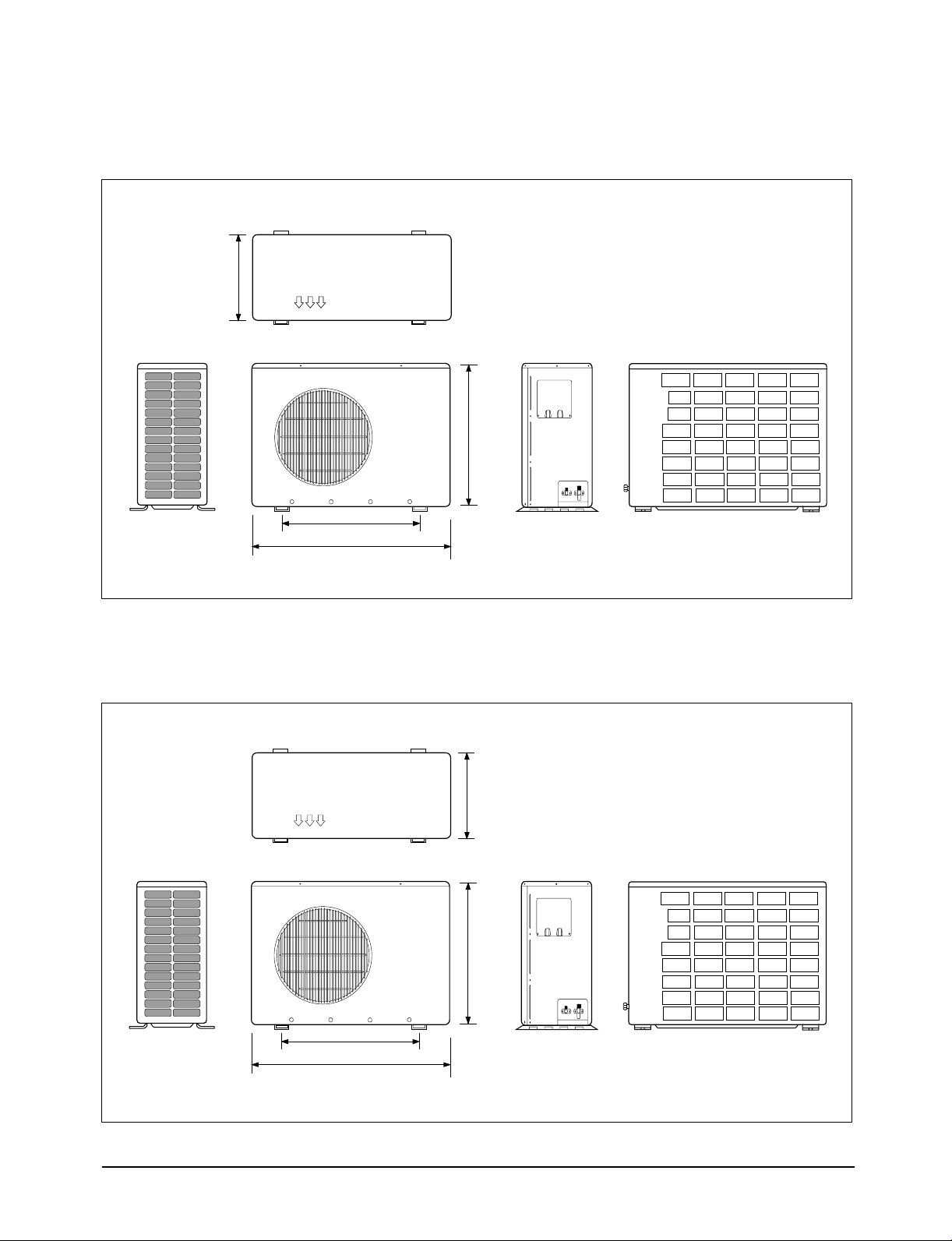
2-2-2 Outdoor Unit
• Outdoor Unit Dimensions (UBH1800E/CH18ZAX/CH18CAX)
320
(Front view) (Rear view)
638
582
787
• Outdoor Unit Dimensions (UBH2400E/CH24ZAX/CH24CAX)
310
(Front view) (Rear view)
638
660
880
Samsung Electronics
2-5
Page 9

;
;
;
;
;
;
;
;
;
;
;
;
;
;
;
;
;
;
;
;
;
;
;
;
;
;
;
Product Specifications
• Outdoor Unit Dimensions
;;;;;
;;;;;
;;;;;
;;;;;
;;;;;
;;;;;
;;;;;
;;;;;
;;;;;
;;;;;
;;;;;
;;;;;
;;;;;
;;;;;
;;;;;
;;;;;
;;;;;
;;;;;
;;;;;
;;;;;
;;;;;
;;;;;
;;;;;
;;;;;
;;;;;
;;;;;
;;;;;
(UCH3600G/CH36ZAX/UCH4400G/CH44ZAX/CH36CAX/CH44CAX)
930
1420
385
Input bolt fixing dimension
A
840mm
2-6
B
415mm
A
B
Samsung Electronics
Page 10

2-2-3 Remote control
• Wired Remote Controller-Buttons and Display
• Wireless Remote Controller-Buttons and Display
Samsung Electronics
2-7
Page 11

Product Specifications
• Centralized Controller
2-8
Samsung Electronics
Page 12
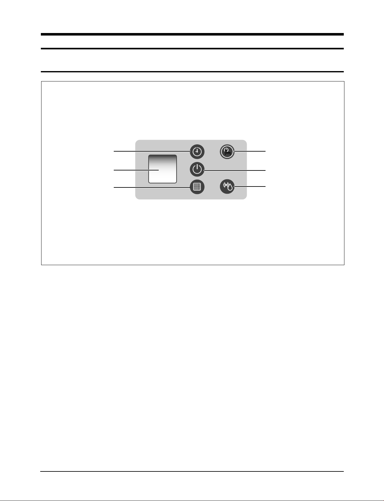
3. Operating Instructions
Timer indicator On/Off button
On/Off indicator
Removing frost indicator
Remote control sensor
Filter Sign indicator
3-1 Display on Indoor unit
Samsung Electronics
3-1
Page 13
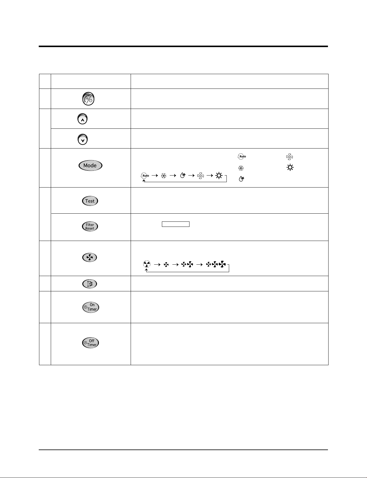
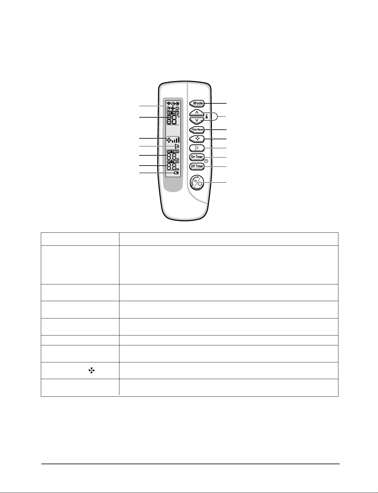
3-2 Name & Functions in Remote Control
3-2-1 Wired Remote Controller-Buttons
NO
1
2
3
4
5
NAMED OF KEY
(UP)
(DOWN)
FUNCTION OF KEY
Power On/Off button to start and stop airconditioner or timer set up
Temp. up button. To increase the temperature by the pressing
the temperature button
Temp. down button. To decrease the temperature by the pressing
the temperature button
Each time you press this button
Mode is changed in the following order
To complete the installation, checks and tests to ensure that the air conditioner is
operating correctly.
When the indicator appeard on the remocon screen, cleaning the air
conditioner filter. After that, press this button.
Each time you press this button,
FAN SPEED is changed in the following order.
FILTER SIGN
: Auto Mode : Blowing
: Cooling Mode : Heat Mode
: Dehumidifying Mode
3-2
6
7
8
Adjust air flow vertically.
The ON Timer enables you to switch onthe air conditioner automatically
after a given period of time that is from 30 minutes to 24 hours.
To cancel the On Time, press the (Set/Cancel) button.
The Off Timer enables you to switch off the air conditioner automatically
after a given period of time that is from 30 minutes to 24 hours.
To cancel the On Time, press the (Set/Cancel) button.
Samsung Electronics
Page 14

3-2-2 Wireless Remote Controller
Operating Instructions and Installation
NO
1
2
3
4
5
NAMED OF KEY
(UP)
(DOWN)
FUNCTION OF KEY
Power On/Off button to start and stop airconditioner or timer set up
Temp. up button. To increase the temperatute by the pressing
the temperature button
Temp. down button. To decrease the temperature by the pressing
the temperature button
Each time you press this button
Mode is changed in the following order
When the indicator appeard on the remoconscreen, cleaning the air
conditioner filter. After that, press the this button.
Each time you press this button,
FAN SPEED is changed in the following order.
FILTER SIGN
: Auto Mode : Blowing
: Cooling Mode : Heat Mode
: Dehumidifying Mode
6
7
8
Adjust air flow vertically.
The ON Timer enables you to switch onthe air conditioner automatically
after a given period of time that is from 30 minutes to 24 hours.
To cancel the On Time, press the (Set/Cancel) button.
The Off Timer enables you to switch off the air conditioner automatically
after a given period of time that is from 30 minutes to 24 hours.
To cancel the On Time, press the (Set/Cancel) button.
Samsung Electronics
3-3
Page 15
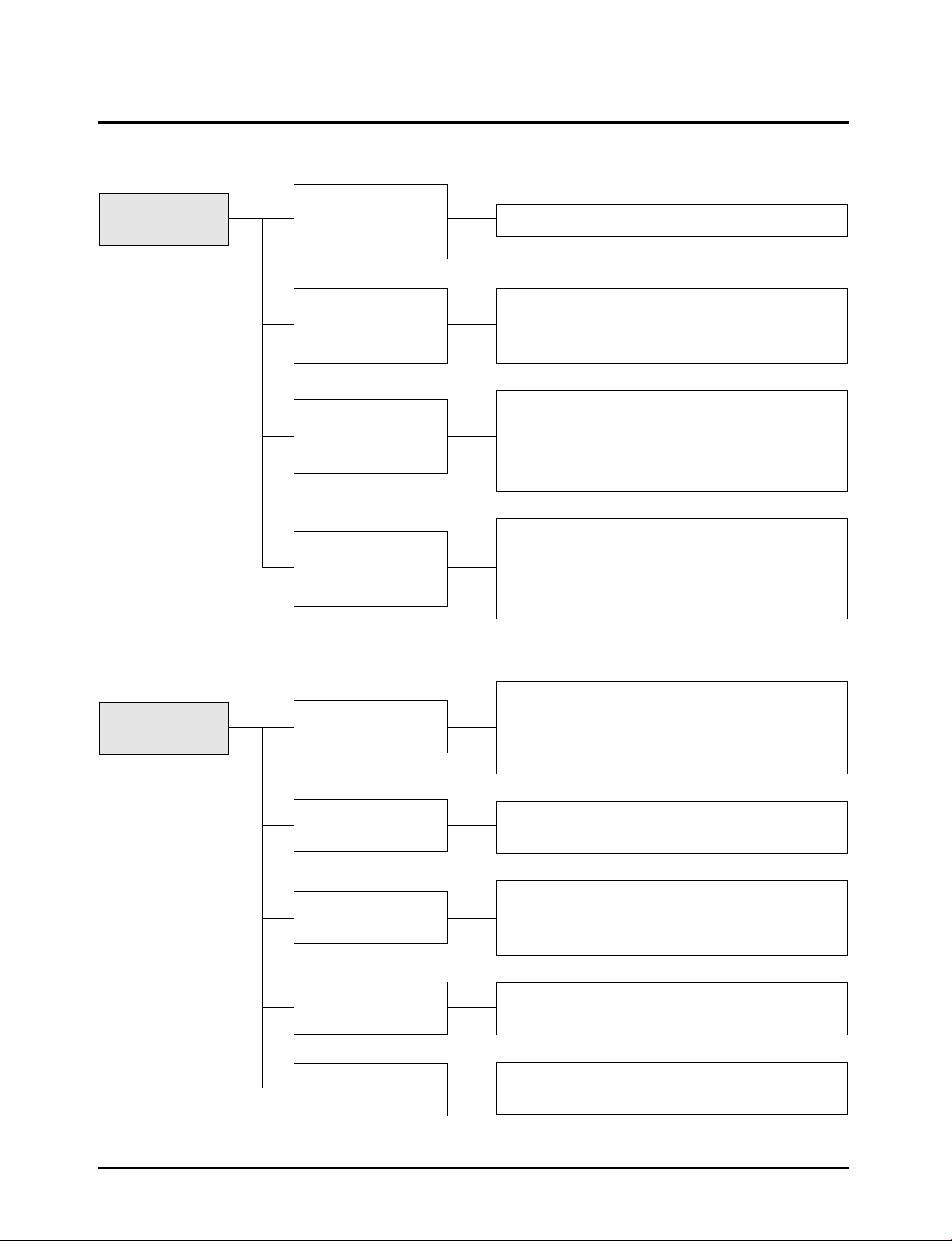
3-3 Control system diagram
Operation
mode
RECEIVE &
DISPLAYUNIT
ON/OFF KEY
WIRELESS
REMOTE
CONTROLLER
WIRED
REMOTE
CONTROLLER
CENTRALIZED
CONTROLLER
* Automatic operation
* Start/Stop, operation mode select, wind volume select,
temperature control, filter reset, reserved operation, up
and down operation(cassette), timer cancel
* Start/Stop, operation mode select, wind volume select,
temperature control, filter reset, reserved operation, up
and down operation(cassette), timer cancel, startup,
group control setting and disassembly
* Centralized control
→ 16 chamber set all on, 16 chamber set all off
→ Each chamber set on/off
→ Centralized control level setting
Operating
selection mode
Automatic
operation
Cooling
operation
Dehumidifying
operation
Blowing
operation
Heating
operation
Automatic change over according to the desired
temperature 18˚C ~ 30˚C.
Automatic wind volume control according to the difference between the desired temperature and room temperature
Room temperature control according to the desired
temperature (18˚C ~ 30˚C)
Humidity control depending upon the difference
between the desired temperature and the room
temperature (18˚C ~ 30˚C)
Indoor fan motor operation only (breeze, weak, strong
wind or weak, strong, turbo)
Room temperature control according to the desired
temperature (16˚C ~ 30˚C)
3-4
Samsung Electronics
Page 16

Operating Instructions and Installation
Wind volume
select mode
Wind flow select
mode
Reserved
operation mode
Manual 3 steps
Wind
volume auto
Up and down
rotation
Timer operation
for
30min ~ 24 hours
Breeze, weak, strong (available at cooling, heating,
blowing)
Auto wind volume control depending on the difference
between the desired temperature and room temperature
Available by wire and wireless remote controller and
operated only for rotation/stop (cassette type model
dedicated)
Selectable by wired & wireless remote controller and
available for start, stop, start/stop reservation
Samsung Electronics
3-5
Page 17

3-4 Micro Computer Block Diagram (Cassette) - Indoor
3-6
Samsung Electronics
Page 18

3-5 Micro Computer Block Diagram - Outdoor
Samsung Electronics
3-7
Page 19

MEMO
3-8 Samsung Electronics
Page 20

4. Installation
4-1 Operation of the Remote Controller (Wired/Wireless receiving board)
4-1-1 Name and function of each part for the wired remote controller
Communication error indicator
On Timer setting
Off Timer setting
Test indicator
Temperature adjustment
buttons
On Timer button
Off Timer button
Test button
Removing frost indicator
Operating mode
Mode selection button
Centralized controller indicator
(In case of installing the Centralized controller)
Temperature setting
Fan speed
Air flow direction
Filter Sign indicator
On/Off & Timer
Set/Cancel button
On/Off indicator
Fan speed
adjustment button
Swing button
Filter Reset button
BUTTON NAME FUNCTION
• Start and stop of operation
On/OFF & Timer
Set/Cancle
Temperature adujustment
(…, †)
On Timer
Off Timer
Test
Mode Selection
Filter Reset
Fan Speed
Flow Direction
- To toggle the operation On and Off.
• When making the reservation
- The reservation time can be set or canceled when pushing the Timer Set/ Cancel button
after adjusting the reservation time with On Timer or Off Timer.
• To increase (
…) or decrease (†) the desired temperature.
• One cycle or continuous operation is available.
• To increase the On reservation time
• One cycle or continuous operation is available.
• To increase the Off reservation time
• One cycle or continuous operation is available.
• Pressing the key for more than 3 seconds with the SET off starts the initial operation (forced
cooling operation for 3 minutes).
• To rotate in the order of AUTO → Cooling → Dehumidifying → Blowing → heating.
• When the filter sign display starts to show the replacement time of filter of indoor unit,
pressing the key after cleaning the filter resets the filter sign.
• The wind mode to rotate in the order of wind select button, Breeze → Weak → Strong →
Wind auto → Breeze.
• The blades ard moving between up and down.
Samsung Electronics
4-1
Page 21
Installation
4-1-2 Name and function of each part for the wireless remote controller
Operating mode
Temperature setting
Fan speed
Air flow direction
On Timer setting
Off Timer setting
Battery discharge indicator
Mode selection button
Temperature adjustment
buttons
Filter Reset button
Fan speed adjustment button
Swing button
On Timer button
Off Timer button
On/Off & Timer Set/Cancel
button
BUTTON NAME FUNCTION
• Start and stop of operation
On/OFF & Timer
Set/Cancle
Temperature adjustment
(…, †)
On Timer
Off Timer
Mode
Filter Reset
Fan Speed( )
Swing button
(Timer Cancel)
- To toggle the operation On and Off.
• When making the reservation
- The reservation time can be set or canceled when pushing the Timer Set/ Cancel button
after adjusting the reservation time with On Timer or Off Timer.
• To increase (…) or decrease (†) the desired temperature.
• One cycle or continuous operation is available.
• To increase the On reservation time
• One cycle or continuous operation is available.
• To increase the Off reservation time
• One cycle or continuous operation is available.
• To rotate in the order of Auto → Cooling → Dehumidifying → Blowing → Heating
• When the filter sign display starts to show the replacement time of filter of indoor unit,
pressing the key after cleaning the filter resets the filter sign.
• The wind mode to rotate in the order of wind select button, Breeze → Weak → Strong →
Wind auto → Breeze.
• The blades are moving between up and down. (In case of Cassette model)
• To cancel the reservation setting (In case of Duct model).
There is no test key separately assigned to the
wireless remote controller.
<When doing the test operation with wireless remote
controller...>
1. Remove both batteries from the wireless remote
controller.
4-2
2. At the state of simultaneous pressing of On Timer key
and Off Timer key, insert the batteries in the wireless
remote controller.
3. When the wireless remote controller is on the TEST
MODE, press On/Off key to make the SET for the Test
operation.
Samsung Electronics
Page 22

4-1-3 Appearance and function wireless receiving board
Installation
Timer indicator
Remote control sensor
Filter Sign
indicator
On/Off button
On/Off indicator
Removing frost
indicator
4-1-4 Opeartion specification of wireless receiving board
PART NAME
DEFROST LAMP
FILTER SIGN LAMP
TIMER LAMP
ON-OFF LAMP
ON-OFF BUTTON
Wireless receiving board and outdoor unit PCB display specification when error occurs
4-1-5
SOURCE & OPERATION SPEC.
RED, lamp on during defrost operation
Green, display during filter cleaning
Green, lamp when setting the reserve operation
Red, lamp during operation on
On/Off toggle operation
REMARK
in ERROR DISPLAY : flickering
in ERROR DISPLAY : filickering
in ERROR DISPLAY : flickering
in ERRO DISPLAY :flickerning
Operated only for automatic mode operation
ERROR MODE
(OUTDOOR DISPLAY)
E1
E5
E6
E9
EA
EC
Ed
Samsung Electronics
CONTENTS OF ERROR
Abnormal on indoor temperature sensor
(4.9[V] and higher, 0.5[V] and lower
Abnormal on indoor pipe temperature sensor
(4.9[V] and higher, 0.5[V] and lower
Abnormal on outdoor temperature sensor
(4.9[V] and higher, 0.5[V] and lower
Float switch detection
Indoor ↔ outdoor communication defect
Indoor unit ↔ wired remote controller
communication defect
Abnormal on outdoor pipe temperature sensor
(4.9[V] and higher, 0.5[V] and lower
WIRELESS RECEIVING BOARD
DISPLAY (INDOOR UNIT)
Reservation LED flickering
(1Hz period)
Operation LED and reservation
LED flickering (1Hz period)
Operation LED and filter LED
flickering (1Hz period)
Reservation LED and filter LED
alternating flickering (1Hz period)
Reservation LED and filter LED
flickering (1Hz period)
Operation LED and reservation
LED alternating flickering (1Hz
period)
Filter LED flickering (1Hz period)
REMARK
Restored when the indoor
temperature sensor is normal
Restored when the indoor pipe
temperature sensor is normal
Restored when the outdoor
temperature sensor is normal
Float switch detection
Re-detecting by operating off
signal after restoring
Restored when outdoor pipe
temperature sensor is normal
4-3
4-3
Page 23
Installation
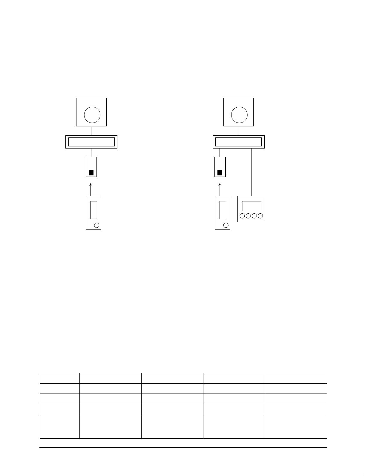
Indoor unit
Wireless
receiving
board
Wireless
remote
controller
Outdoor unit
Indoor unit
Wireless
receiving
board
Wireless
remote
controller
Wired remote
controller
Outdoor unit
4-1-6 Example of remote controller control
1 chamber wireless remote controller single operation and 1 chamber wireless remote controller + wired
remote controller combination control
Example of 1 chamber single operation
(wireless remote controller)
* In case of 1 chamber single operation (wireless remote controller+wired remote controller), both setting of wired remote controller
to MASTER/SLAVE is available.
Example of 1 chamber single operation
(wireless + wired remote controller)
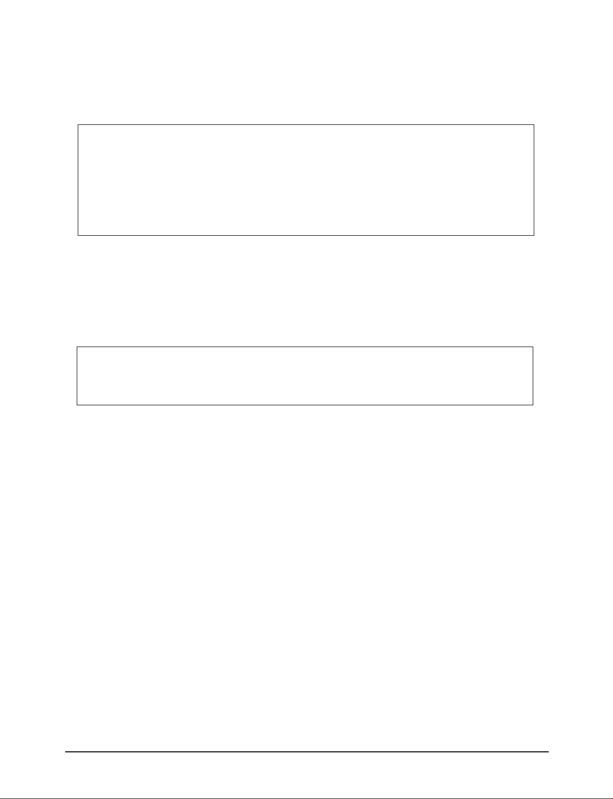
<Setting of wired remote controller to MASTER MODE >
1. Put off the power.
2. For the combined use of wired remote controller
and wireless remote controller, put on the option
switch(DS01)4 of wired remote controller.
✽ After resetting the option in the wired remote
controller, be sure to put the power on again so
that the set option can be applied.
3. Putting off the option switch 4 of wired remote
controller disables the control by wireless remote
controller.
4. Put on the power.
4-1-7 PCB option and switch(DS01) setting of wired remote controller
DIP SWITCH NO
1
2
3
OPTION ITEM
Basic specification
Indoor unit control
Basic specification
SW ON
Group control
SW OFF
-
-
Indoor unit 1 chamber control
-
-
DEFAULT
Fixed to OFF
OFF
Fixed to OFF
4-4
4
Combined use of
wireless remote
controller
Able to operate of wired
remote controller
(SLAVE MODE)
Disable to operate the
wireless remote controller
(MASTER MODE)
OFF
Samsung Electronics
Page 24

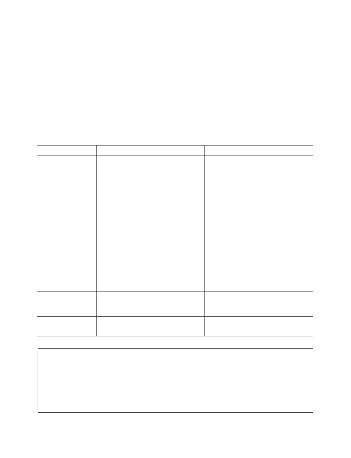
4-1-8 Function comparison of wired remote controller vs wireless remote controller
Installation
In case of control for the wired remote controller
and wireless remote controller installed
individually, almost similar functions are
performed, and in case of combined use of wired
and wireless remote controllers, Enalbe/Disable
PART NAME
Operation ON/OFF
Wind flow setting
Wind volume setting
Group operation
Test operation
Operation mode setting
Reservation function
Timer cancel
Temperature setting
WIRED REMOTE CONTROLLER
ON/OFF available
Up and down control available (Cassette model)
Breeze/Weak/Strong/Wind auto adjustment available
16 chamber group operation available
Test operation by test button
Settable of auto/cooling/
dehumidifying/blowing/heating
Start/stop/start-stop reservation available
Timer cancel button provided (Duct model)
Cooling : 18˚C ~ 30˚C
Heating : 16˚C ~ 30 ˚C settable
can be set at the wired remote controller for the
wireless remote controller but the 16 chambers
operation can be done only from wired remote
controller.
WIRELESS REMOTE CONTROLLER
ON/OFF available
Up and down control available (Cassette model)
Breeze/Weak/Strong/Wind auto adjustment available
16 chamber group function not available
Available by combination of button during the power
reset without test button
Settable of auto/cooling/
dehumidifying/blowing/heating
Start/stop/start-stop reservation available
No timer cancel button
Cooling : 18°C ~30°C
Heating : 16°C ~30°C settable
Filter reset
Centralized control display
Self-diagnosis among the
group control
Error display
Master/slave setting
Filter reset button provided
Displayed as centralized control
To display while scanning the installed set
during reset
Displayed as 2 digit segment
Master/slave settable by PCB option switch
Filter reset button provided
No function
No function
No function
No function
4-1-9 Option and dip switch setting(SW2) of ass'y main in PCB
DIP SWITCH
1
2
3
4
5
OPTION ITEM
VENTILATOR FAN
DRAIN PUMP
FLOAT SWITCH
FILTER CLEANING PERIOD
INDOOR FAN MOTOR SPEED
SW ON
Not installed
Installed
Installed
1000 Hr
NORMAL SPEED
SW OFF
Installed
Not installed
Not installed
2000 Hr
HIGH SPEED
DEFAULT
-
-
-
-
-
Samsung Electronics
4-5
Page 25

4-2 Control of the Remote Controller
Indoor unit
"A" chamber
Wireless
receiving board
Wireless
remote
controller
Outdoor unit
Wired remote
controller
Indoor unit
"B" chamber
"C" ~"N" chamber
Wireless
receiving board
Wireless
remote
controller
Outdoor unit
Wired remote
controller
"O" chamber
Wireless
receiving board
Wireless
remote
controller
Wired remote
controller
"P" chamber
Wireless
receiving board
Wireless
remote
controller
Wired remote
controller
4-2-1
Chamber Group Control(Wireless remote controller + Wired remote controller system)
• The 16 chamber remote controller operation by wired remote controller can be simultaneously performed
all for 16 chambers through setting the 16 chambers to one group through one wired remote controller.
• While operated in Group, the control by wireless remote controller installed in all chambers (“A” ~ “F”)
is disabled except the wired remote controller installed in the “A” chamber and the simultaneous use
with the option item, the centralized controller is also disabled.
4-2-2
1. Setting of indoor unit Main PCB
The group operation of 16 chambers and operation method by wired remote controller
• Put off all of set power installed in each room.
• Remove the centralized controller if any is used already.
• Remove CN20 connector and wire of main PCB of Indoor unit except the one installed in “A” with
reference of the figure.
• Connect the communicating line from “A” chamber to “F” chamber.(R1<->R1, R3<->R3)
• Connect the “R1”, “R2” and “R3” of indoor terminal board installed to the “R1”,”R2”,”R3” of wired
remote controller, respectively.
• Adjust the address of digital switch of indoor unit PCB in “A” chamber to “0”.
Adjust the address of digital switch of indoor unit PCB in “B” chamber to “1”. In such a way, adjust the
address of digital switch up to chamber “F”.
4-6
Samsung Electronics
Page 26
• Put on the set power installed in each chamber.
Caution :
• During the connection, connect the “R1” of indoor unit terminal board installed in each chamber with “R1”.
• During the connection, connect the “R3” of indoor unit terminal board installed in each chamber with “R3”.
• Do not connect the terminal R2 of indoor unit terminal board from “B” to “F” chamber except A” chamber.
• The option item, centralized controller shall be removed since the simultaneous use with wired remote controller is disable
during the group control.
• Adjust the address of indoor unit digital switch installed in each chamber so that it might not be duplicated.
2. Setting of wired remote controller
• Put off the set power where the wired remote controller is installed.
• Put on the option switch SW2(DS01) of wired remote controller.
• Put on the set power where the wired remote controller is installed.
Installation
Caution :
• The option can be applied when the power is put again after resetting the option of wired remote controller. Be sure to keep the
set power on/off after option setting.
Samsung Electronics
4-7
4-7
Page 27

R1 R2 R3
R1 R2 R3
Indoor unit
"A" chamber
R1 R2 R3
Indoor unit
"B" chamber "C" ~ "N" chamber
R1 R2 R3
Indoor unit
"O" chamber
R1 R2 R3
Indoor unit
"P" chamber
Wired remote
controller
Installation
4-2-3 Operation method of wired remote controller
Figure. 16 Chamber Group Control Connection Diagram
• Press the ON/OFF button of wired remote controller to be on.
At the time, the set installed from A chamber to F chamber is getting on in order with the interval of 2
seconds.
• Select the operation of auto/cooling/dehumidi-fying/blowing/heating by pressing MODE BUTTON.
• Select breeze/weak/strong/wind auto by pressing the wind volume button.
• Adjust the temperature set button to set the desired temperature.
✽ For reference
• The communication between wired remote
controller and indoor unit is made through the
synchronization with the output signal of zero
cross detect circuit, and when 50Hz power is
used, it has the 50bps transmission speed and
Indoor unit
RECEIVE MODE
SEND MODE
Wired remote
controller
when it has 60Hz power it has 60bps transmission
speed. The transmission data between the wired
remote controller and indoor unit is shown as in
the figure.
Since the communication data between wired remote
controller and indoor unit is consisting of total
10Byte, 2 seconds are required when using 50Hz
power.
• For the communicating time with 16 chambers
during the normal operation, 32 seconds are
required and for the time with 16 chamber during
the reservation operation, 64 seconds are required
Caution :
• The power of each chamber shall be used with the one
having the same frequency during the group operation by use
of wired remote controller.
• The communicating line between the wired remote controller
and indoor unit shall be of 100 m at maximum.
due to the increase of communicating data.
4-8
Samsung Electronics
Page 28
4-2-4 Startup method by wired remote controller
Installation
Startup in case of the “A” chamber single
operation
• Put on the set power.
• Adjust the address of digital switch of indoor
unit PCB to “0”.
• Put ON the option switch(DS01) N02 of wired
remote controller PCB.
• Put on the set power.
• Press the test button of wired remote controller
Error Code
01
05
06
09
Indoor unit room thermistor error
Indoor unit pipe thermistor error
Outdoor unit thermistor error
Float switch open error
Meaning
for more than 3 seconds.
• The set is operated for 3 minutes by the forced
cooling operation and the set is off after 3
minutes.
• The error occurring during the test operation is
displayed on the wired remote controller
windows and it shall be referred to the
following table.
Checking Area
• Indoor unit thermistor available or not and
disconnected
• Indoor unit PCB
• Indoor unit pipe thermistor
• Indoor unit PCB
• Outdoor unit thermistor
• Outdoor unit PCB
• Drain pump, float switch
• Drain system
• Dip SW2 of indoor unit main PCB
(If the drain pump is not installed, SW2 and
SW4 shall be at the Off position.)
0A
0C
0D
Indoor unit ↔ outdoor unit communicating error
Wired remote controller ↔ indoor unit
communication error
Outdoor unit pipe thermistor error
• Indoor unit ↔ outdoor unit communicating
error
• Indoor unit ↔ outdoor unit communicating
cable
• Indoor unit PCB, Outdoor unit PCB
• Wired remote controller ↔ indoor unit
communication cable
• Indoor unit main PCB
• Outdoor unit pipe thermistor
• Outdoor unit PCB
Caution :
• Unless the address of digital switch of indoor unit PCB is set to “0” in case of “A” chamber single operation, the control by the wired
remote controller is disabled.
• The power of SET shall be put on again after the resetting of wired remote controller option so that the the set option can be applied.
Be sure to keep the power on/off of SET before and after the setting.
• The first digit of error code displayed during the single operation and group operation may be different. The first digit(MSB) stands for
the address of the set where the error occurs. Since it is the single operation, the address of SET is “0”.
Samsung Electronics
4-9
4-9
Page 29

Installation
Startup of group operation
• Put off the power of SET.
• Adjust the addresses of digital switch of indoor
unit PCB to “0”~”15”, respectively.
• Put on the option switch SW2 of wired remote
controller PCB.
• Put on the power of SET.
• On the wired remote controller display, the digits
“00” → “11” → “22” → are displayed up to “FF”.
After “FF” display, the wired remote controller is
automatically set to the preserved operation
status of indoor unit of chamber “A”.
Error Code
*1
*5
*6
Indoor unit room thermistor error
Indoor pipe thermistor error
Outdoor unit thermistor error
Meaning
• If the current SET of chamber “A” is ON, put the
set off by pressing the ON/OFF button.
Only at the SET off of chamber “A”, the TEST mode
is enabled.
• Press the TEST BUTTON of wired remote
controller for more than 3 seconds.
• If the SET is operating for 3 minutes through
forced cooling operation, the SET is off after 2
minutes.
• The Error occurring in the TEST operation
displays in the wired remote controller display
window and is referred to the following table.
Checking Area
• Indoor unit thermistor exist or not disconnected
• Indoor unit PCB
• Indoor unit pipe thermistor
• Indoor unit PCB
• Outdoor unit thermistor
• Outdoor unit PCB
*9
*A
*C
*D
Float switch open error
Indoor unit ↔ outdoor unit communication error
Wired remote controller ↔ indoor unit
communication error
Outdoor unit pipe thermistor error
• Drain pump, float switch
• Drain system
• Dip SW2 of indoor unit main PCB
(If drain pump is not installed, SW2 and SW4
shall be at OFF position.)
• Indoor unit ↔ Outdoor unit communication cable
• Indoor unit PCB, outdoor unit PCB
• Wired remote controller ↔ indoor unit
communication cable
• Indoor unit main PCB
• Outdoor unit pipe thermistor
• Outdoor unit PCB
Caution :
• Test operation is disabled when the chamber “A” is on after initialization of wired remote controller.
• The communication time between wired remote controller and indoor unit is required for 2 seconds. If any one of set is ON, be sure to
put it off by pressing the ON/OFF button and start the TEST operation after 35 seconds at minimum.(The communication time with all
chambers : 16 x 2 seconds = 32seconds)
• For the reservation operation, the communication time between all 16 chambers is required for 64 seconds due to the increase of
communication data.
• The first digit (MSB) of error code displayed during the group operation stands for the address of SET where the error occurs.
4-10
Samsung Electronics
Page 30
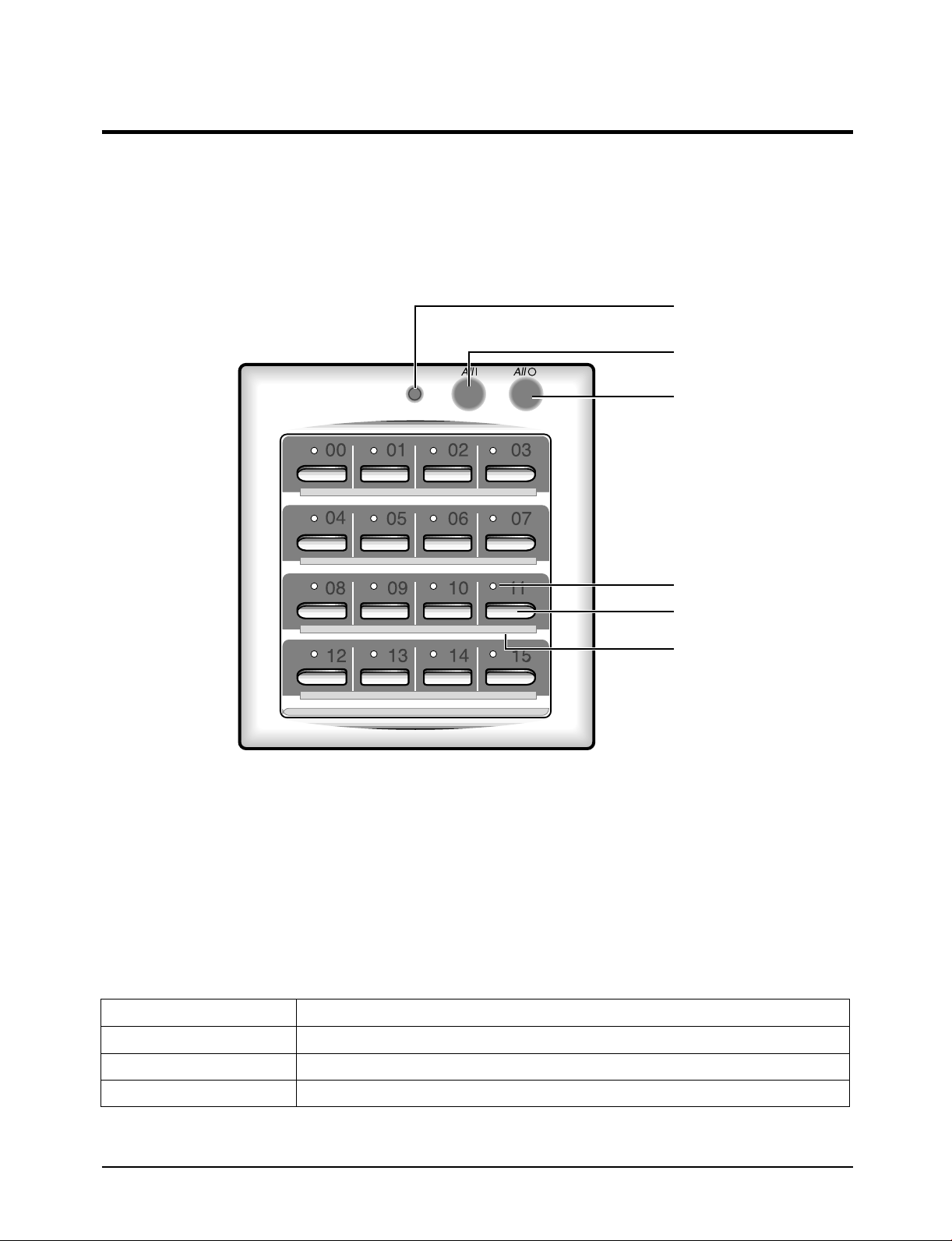
4-3 Controller
4-3-1 Appearance and characteristics of Centralized Controller
The centralized controller is installed on the wall.
The centralized controller is an optional accessory.
Operating lamp
All On button
All Off button
NOTE : Operating lamp comes on when at least one air conditioner
connected to the centralized controller is operating.
• Since the centralized controller has the relay
equipment, the option mounted on the indoor
unit, the On/Off can be set for 16 chambers
through the modem communication.
• Linkage of wired remote controller to wired
remote controller is available by 3 kinds of level.
BUTTON NAME
On/Off indicators
On/Off buttons
Index
• The maximum extended distance of 1 Km is
possible through modem communication. (the
relay equipment is installed at the option item,
indoor unit)
• The connection by non-polarity method is easy.
FUNCTION
ALL1
ALL0
"01" ~ "16"
Samsung Electronics
• To put on all 16 chambers' set.
• To put off all 16 chambers' set.
• To put on/off set assigned with the number.
4-11
Page 31
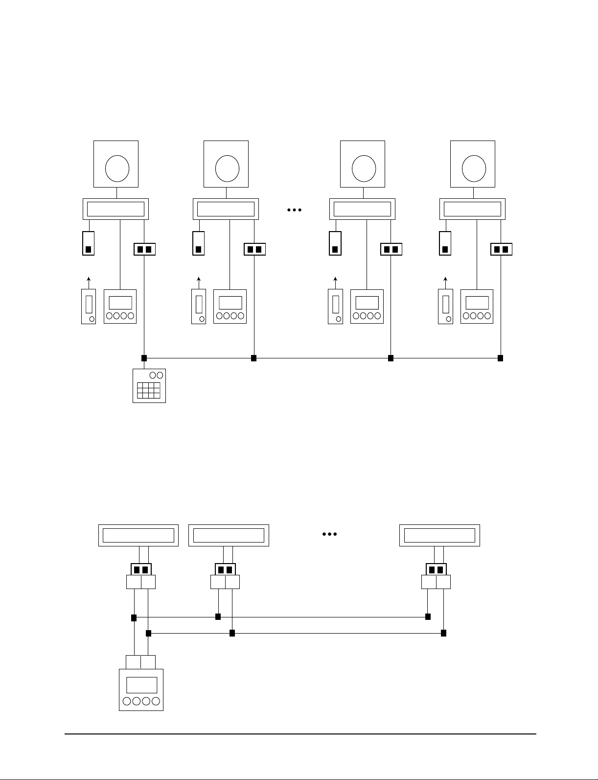
Installation
Indoor unit
"A"
chamber
Transmitter
Wireless
receiving board
Wireless
remote
controller
Outdoor unit
Wired remote
controller
Centralized controller
"C" ~"N" chamber
16
chamber
Indoor unit
"B"
chamber
Transmitter
Wireless
receiving board
Wireless
remote
controller
Outdoor unit
Wired remote
controller
Indoor unit
"O"
chamber
Transmitter
Wireless
receiving board
Wireless
remote
controller
Outdoor unit
Wired remote
controller
Indoor unit
"P"
chamber
Transmitter
Wireless
receiving board
Wireless
remote
controller
Outdoor unit
Wired remote
controller
01 02
Indoor unit
"A" chamber "B" chamber "P" chamber
"C" ~ "O" chamber
Transmitter Transmitter Transmitter
01 02 01 02
Indoor unit
01 02
Indoor unit
4-3-2 Example of the centralized control system configuration
Figure. 16 Chambers Centralized Control (wireless remote controller + wired
remote controller + centralized controller) System
4-3-3 Chambers Cnetralized Control System Connection Diagram
4-12
Samsung Electronics
Page 32

Installation
4-3-4 Centralized control operation method
1. Setting of indoor unit
• Put off the set to be installed.
• Put off the power of the centralized controller.
• Mount the Transmitter, the option item on the indoor unit set terminal board.
• Adjust the address of digital switch of Transmitter mounted. (Adjust the address of Transmitter
mounted in chamber “A” to “0” and “B” to “1”... continue the adjustment up to “F” to “F”)
• Connect the terminals O1 and O2 of the terminal board mounted on the centralized controller to the O1
and O2 of the terminal board installed in chamber “A”.
• If the wired remote controller is installed, be sure to put off the SW2(DS01) of PCB option switch.
• Remove the centralized controllers installed at chamber “B” to chamber “F” if any except the A
chamber.
• Adjust the address of digital switch of indoor unit PCB to “0”.
• Connect O1 and O2 of terminal board installed in chamber A to O1 and O2 of terminal board installed
in chamber B.
• Continue to connect O1 and O2 of terminal board mounted on indoor unit in chamber B ~ F to O1 and
O2 of terminal board of centralized controller(recommended).
2. Setting at centralized control side
• Adjust the applicable level of centralized controller with the reference of the table.
3. When the setting is finished at indoor unit and centralized controller,
• Put on the power of installation completed set of each chamber.
• Put on the power of centralized controller.
DIP SWITCH
LEVEL 0
LEVEL 1
LEVEL 2
Error Code
LED flickering
SW1
OFF
OFF
OFF
SW2
OFF
OFF
OFF
Communication error between indoor unit and
centralized controller
SW3
OFF
OFF
ON
Meaning
SW4
OFF
ON
OFF
Set operation according to the final controlled one among the
centralized controller, wire, and wireless
When centralized controller OFF : disable to control wired and
wireless
When centralized controller ON : enable to control wired and
wireless
Enable to control only in the centralized controller
Disable to control the wired and wireless remote controller
Transmitter, indoor unit, centralized controller
REMARK
Checking Area
Caution :
• The communication between centralized controller and Transmitter is modem method and there is no polarity but connect “O1”
terminal to “O1” terminal and “O2” terminal to “O2”terminal.
• The address of Transmitter mounted on each indoor unit shall not be duplicated.
• After the resetting of operation level of centralized controller, it is not necessary to reset the power differently from that of wired
remote controller. In other words, the operation level can be reset even during the operation if required.
Samsung Electronics
4-13
Page 33

Installation
4-3-5 Operation specification of wireless and wired remote controller while using the
centralized controller.
Centralized
controller
LEVEL 0
LEVEL 1
LEVEL 2
Wired remote
controller
MASTER
Wired remote controller has the priority of control
over the wireless.
A area : to be operated be the final input of
centralized controller and wired remote controller,
and the wireless remote controller does not work
even through installed.
B area : The wired remote controller operates only
when the centralized controller is on but the wireless
remote.
C area : only the centralized controller operates but
the wired and wireless remote controller do not
work.
SLAVE
Wired remote controller has not the priority of control
over the wireless.
D area : to be operated by the final input of
centralized controller, wired remote controller and
wireless remote controller.
E area : the wired and wireless remote controller
operate only when the centralized controller in on.
F area : only the centralized controller operates but
the wired and wireless remote controller do not
work.
4-14
Samsung Electronics
Page 34

4-4 Selecting Area for Installation
Select an area for installation that is suitable to
the customer’s needs.
4-4-1 Indoor Unit
1. Make sure that you install the indoor unit in an
area providing good ventilation. It must not be
blocked by an obstacle affecting the airflow near
the air inlet or the air outlet.
2. Make sure that you install the indoor unit in an
area allowing good air handling and endurance
of vibration of the indoor unit.
3. Make sure that you install the indoor unit in an
area where there is no source of heat or vapor
nearby or direct sunlight.
4. Make sure that you install the indoor unit in an
area from which hot or cool air will spread
evenly in the room.
10. Please use the given accessories to install the
indoor unit. (set of slings)
• Check that the installed location is strong
enough to hang the indoor unit on.
• The distances of the following should be
limited:
The lengths of refrigerant tube 30 m.
The height difference between indoor and
outdoor unit should be less than 15 m.
5. Make sure that you install the indoor unit in an
area that provides easy pipe connection with
the outdoor unit, and easy drainage for
condensed water.
6. The ceiling should not be inclined by more than
2 degrees.
7. The distance between the indoor unit and the
outdoor unit should not be longer than A.
(recommended distance between two units is 5m.).
and the height difference between the indoor unit
and the outdoor unit should be less than B.
Model
A
B
30m ✳✳18/24✳✳
50m ✳✳36/44✳✳
15m ✳✳18/24✳✳
25m ✳✳36/44✳✳
8. There should be enough space around the indoor
unit to provide easy installation and service.
★
150cm
★
Air flow out
Air flow out
150cm
20 cm
20cm
Air flow in
100cm
Air flow in
20cm
Air flow out
20cm
Air flow out
★
★
150cm
150cm
9. There are 4 ways to select the number of air outlets
(see the figure). The selection depends on the
shape of the room and installation location of
indoor units.
Samsung Electronics
Remark : The distance of “★” sign will equal 20 cm ,
if you close the air outlet on that side.
4-15
Page 35
0.15 m.
1.5 m.
Building
Wall
Installation
4-4-2 Outdoor unit
1. Make sure that you install the outdoor unit in
an area not exposed to the rain or direct
sunlight. (Install a separate sunblind if exposed
to direct sunlight.)
2. Make sure that you install the outdoor unit in
an area, not amplifying noise or vibration,
especially to avoid disturbing neighbours. (Fix
the unit firmly if it is mounted on a high place.)
3. Make sure that you install the outdoor unit in
an area providing good ventilation and which is
not dusty. It must not be blocked by any
obstacle affecting the airflow near the air inlet
and the air outlet.
4. Make sure that you install the outdoor unit in
an area free from animals or plants.
5. Make sure that you install the outdoor unit in
an area not blocking the traffic.
6. Make sure that you install the outdoor unit in
area easy to drain condensed water.
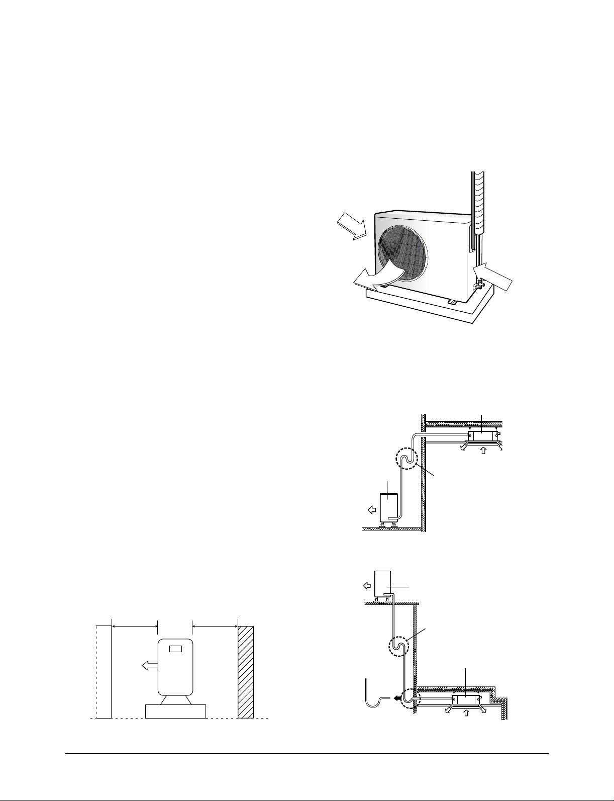
10. If you install the outdoor unit in a location that
has open airflow, you should install the outdoor
unit in a direction that airflow out from the
outdoor unit is perpendicular to the open air
flow direction.
Open Air
Air flow out
Open Air
11. Install the oil trap according to the installation
condition. (see the figure)
a. When the indoor unit is above the outdoor unit
Indoor unit
7. If installed on a desk, it should not be installed
in a direction that puts open airflow is against
airflow from the outdoor unit. It will make the
air conditioner malfunction.
8. Do not let hot air flow into the outdoor unit
because the air conditioner will malfunction.
The hot air may come from other near-by the
outdoor unit or heating equipment or itself.
9. If install the outdoor unit directly against the
wall, the minimum distance between the
outdoor unit and the wall should be 1.5 m.
Outdoor unit
b. When the outdoor unit is above the indoor unit
Radius
5cm
Oil trap
(suction tube)
Oil trap
(Must be installed every 6m)
Outdoor unit
Oil trap
(Must be installed every 6m)
Indoor unit
4-16
Samsung Electronics
Page 36

Installation
12. You should leave spacing around the outdoor
unit at least according to the figure for easy
installation, service and ventilation.
0.1 m.
0.1 m.
0.35 m.
13. Install the outdoor unit on a rigid base.
14. Fasten the outdoor unit to the base by using
bolts or nuts.
15. In case of hanging the outdoor unit, you should
hang it on a rigid wall area and use right angle
steel thickness of 4 mm. as a holder.
Rigid wall
Fasten right angle steel by using screws
Right angle steel thickness of 4 mm.
Caution :
It is harmful to the air conditioner if it is used in the following
environments: greasy areas (including near machines), salty
areas such as coast areas, areas where sulfuric gas is present
such as hot spring areas, large variance in electricity voltage
such as in a factory. Contact your dealer for advice.
Samsung Electronics
4-17
Page 37
Installation
O
WNER'S
INSTRUCTIONS
SPLIT-TYPE
R
OOM AIR CON
D
I
T
I
O
NE
R
OWNE
R
'S
I
NSTRUC
T
IONS
MAN
UA
L DE I
NS
TRUC
CIO
N
ES
IS
TRU
Z
I
ONI PER L'USO
M
ANUAL D
E
INSTR
UÇ
Õ
ES
MANUEL D'UTILISATIO
N
GEB
RA
UCHSA
NWEISUNG
Splut-type Room Air
Co
ndi
t
ioner
Aire
acon
dicionado do
m
é
st
ico sist
ema Split
Con
d
izionator
e d'
aria p
er
ambienti ad unità Separate
Aparelho de ar cond
i
c
i
onado
ti
po S
pl
it
Cl
i
matiseur de
type séparé
Get
e
ilte raumklim
aa
nlage
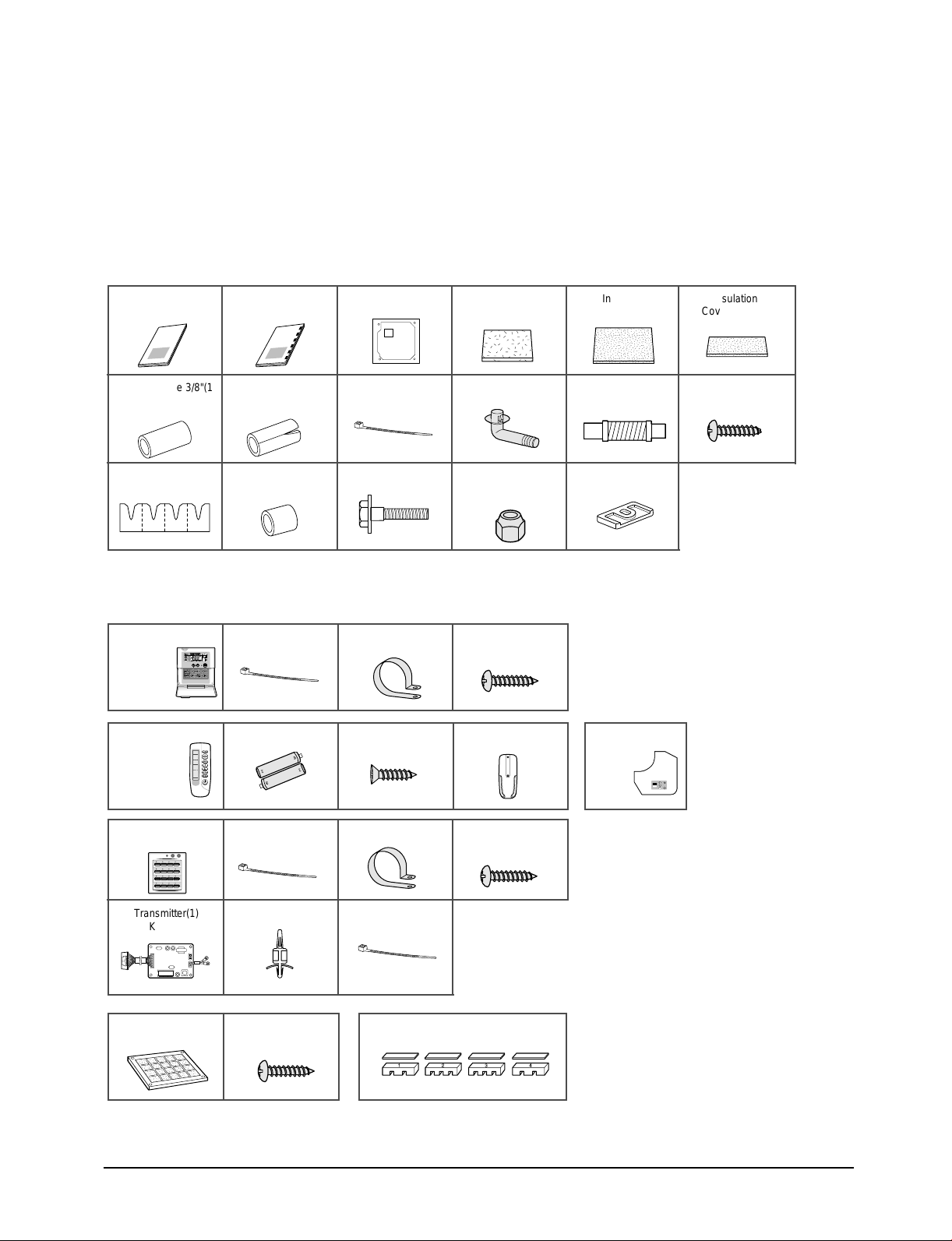
4-4-3. Air Conditioner and Accessories
The following accessories are supplied with the air conditioner. The quantities are indicated in parantheses.
Basic Accessories
Owner’s
Instructions(1)
Insulation Pipe 3/8"(1)
Insulation Pipe 5/8"(1)
Insulation Pipe 3/4"(1)
Pad Stopper(1) Insulation Drain Sub
Installation
Manual(1)
Insulation Drain
Pipe(1)
(1)
Optional Accessories
Wired Remote
Controller(1)
KR-H50210
Wireless Remote
Controller(1)
KR-H40200
Cable-Tie(2) Cable Clamp(5) M4 X 16 Tapped
Battery(2) M4 X 16 Tapped
Pattern Sheet(1) Insulation
Cover Drain(1)
Insulation
Cover Pipe(2)
Insulation
Cover Band(1)
Cable-Tie(5) Drain Plug(1) Flexible Hose(1) M4 X 12 Tapped
Screw(4)
Bolt(4)
Flare Nut 3/8"(1)
Flare Nut 5/8"(1)
Flare Nut 3/4"(1)
Rubber Leg (4)
Screw(7)
Screw(2)
Remote Controller
Holder(1)
Receiver & Display
Unit(1)
(KRE-H1000)
Centralized Controller(1)
KR-H60110
Transmitter(1)
Cable-Tie(2) Cable Clamp(5) M4 X 16 Tapped
Screw(7)
Spacer Support(4) Cable-Tie(2)
KT-A00
Bio-Pure Filter(1)
KF-C1B0
M4 X 10 Tapped
Screw(4)
Air blocking Kit(1) KAB-A00
NOTE : Refrigeration pipes and their insulating materials, power cables are not supplied.
4-18
Samsung Electronics
Page 38

4-5 Installation Diagram of Indoor Unit and Outdoor Unit
4-5-1 Piping, Drain Hose Direction
Respect the clearances and maximum lengths indicated in the diagram below when installing the unit.
Liquid Refrigerant tube
Gas Refrigerant tube
“H”metres
maximum
10cm
✴ The appearance of the outdoor unit
may be different from the diagram
depending on the model.
Space requirement when installing the indoor unit
255mm
1000mm or more
230mm
17mm
Drain hose
15cm
1500mm or more
20mm
10cm
35cm
Model
✴✴18✴✴
✴✴
24
✴✴
L30H
15
Samsung Electronics
4-19
Page 39

Installation
4-5-1 Piping, Drain Hose Direction
Respect the clearances and maximum lengths indicated in the diagram below when installing the unit.
Liquid Refrigerant tube
Gas Refrigerant tube
Drain hose
“H”metres
maximum
Model
✴✴36✴✴
✴✴
44
✴✴
L50H
25
10cm
10cm
✴
The appearance of the outdoor unit
may be different from the diagram
15cm
depending on the model.
Space requirement when installing the indoor unit (In case of✴✴36✴✴/✴✴44✴✴)
1500mm or more
305mm
1000mm or more
288mm
17mm
20mm
35cm
4-20
Obstacle
Samsung Electronics
Page 40
Installation
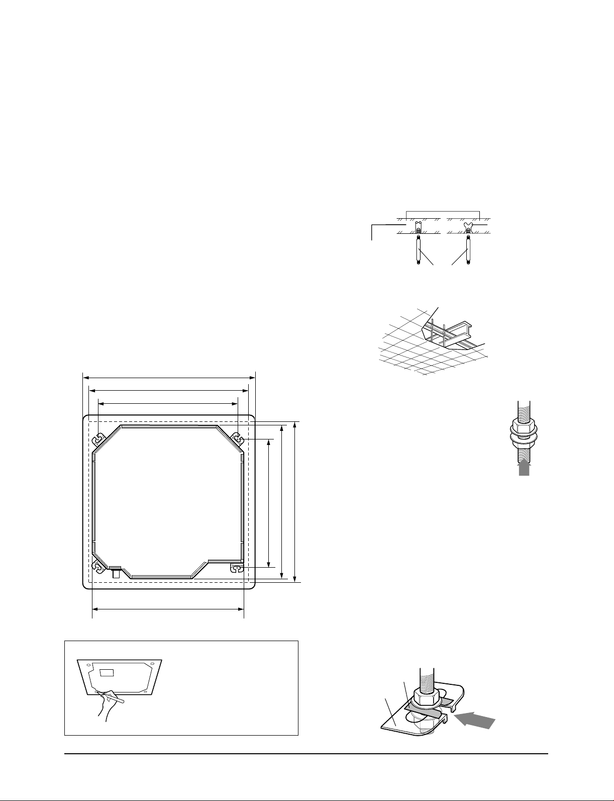
4-5-2 Preparing the Area for Installation
Preparing the Area for Installation of Indoor Unit
1. Measure the distance between ceiling and
ceiling wall.
2. Place the pattern sheet on the ceiling.
3. Cut the ceiling to install the indoor unit by
attaching the pattern sheet onto the ceiling.
Then cut the pattern sheet and ceiling in section
A and make a hole in the ceiling at the position
of the hook. Use the plummet to mark the
position on the ceiling wall, which is vertically
in line with the hole in the ceiling, and make
these 4 holes in the ceiling wall.
4. Insert bolt anchors, use existing ceiling supports
or construct a suitable support as shown in
figure.
950 (Dimensions of Front Panel)
880 (Cutting Dimensions of Ceiling)
766 (Space of Suspension Bolts)
5. Install the suspension bolts depending on the
ceiling type.
IMPORTANT : Ensure that the ceiling is strong enough
to support the weight of the indoor unit.
Before hanging the unit, test the strength
of each attached suspension bolt.
Concrete
Insert
Hole in anchor
Hole in plug
Suspension bolt(M8)-field supply
Ceiling support
6. Screw eight nuts to the suspension
bolts making space for hanging the
indoor unit.
840 (Outer Dimensions)
Samsung Electronics
840 (Outer Dimensions)
699 (Space of Suspension Bolts)
NOTE :
◆ Since the diagram is made of
paper, it may shrink or stretch
slightly due to temperature or
humidity. For this reason, before
drilling the holes maintain the
correct dimensions between the
markings; refer to page 2-3.
IMPORTANT : You must install the suspension bolts
more than four when installing the indoor
unit.
7. Hang the indoor unit to the suspension bolts
880 (Cutting Dimension of Ceiling)
between two nuts.
NOTE: ◆ Tubing must be laid and connected inside the
ceiling when suspending the unit. If the ceiling
is already constructed, lay the tubing into
position for connection to the unit before
placing the unit inside the ceiling.
8. Screw the nuts to suspend the unit. Cut a pad
stopper and place it on the bracket at this time.
Pad stopper
Bracket
4-21
Page 41
Installation
9. Adjust the unit to the appropriate position
considering the installation area for the front
panel.
9-1 Place the pattern sheet on the indoor unit.
9-2 Adjust a space between the ceiling and the
indoor unit by using the gauge of
dimensions.
9-3 Fix the indoor unit securely after adjusting
level of the unit by using a leveler.
9-4 Remove the pattern sheet, connect the other
cables and install the front panel.
Indoor Unit
17mm
Gauge of
Dimensions
20mm
Ceiling
4-5-3 Connecting the connection cord
The indoor unit is powered from the outdoor unit via the
connection cord.
1. Remove the screws on the electrical component
box and remove the cover plates.
2. Route the connection cord through the side of
the indoor unit and connect the cable to
terminals as shown in page 4-23, 4-24.
3. Route the other end of the cable to the outdoor
unit through the ceiling & the hole on the wall.
4. Reassemble the electrical component box cover,
carefully tightening the screws.
5. For further details on how to plug the other end
of the connection cord into the outdoor unit,
refer to page 4-25, 4-26.
Cable Clamp
(1ø, 220V-240V~, 50Hz)
Cable Clamp
(3ø, 380V-415V~, 50Hz)
4-22
Samsung Electronics
Page 42
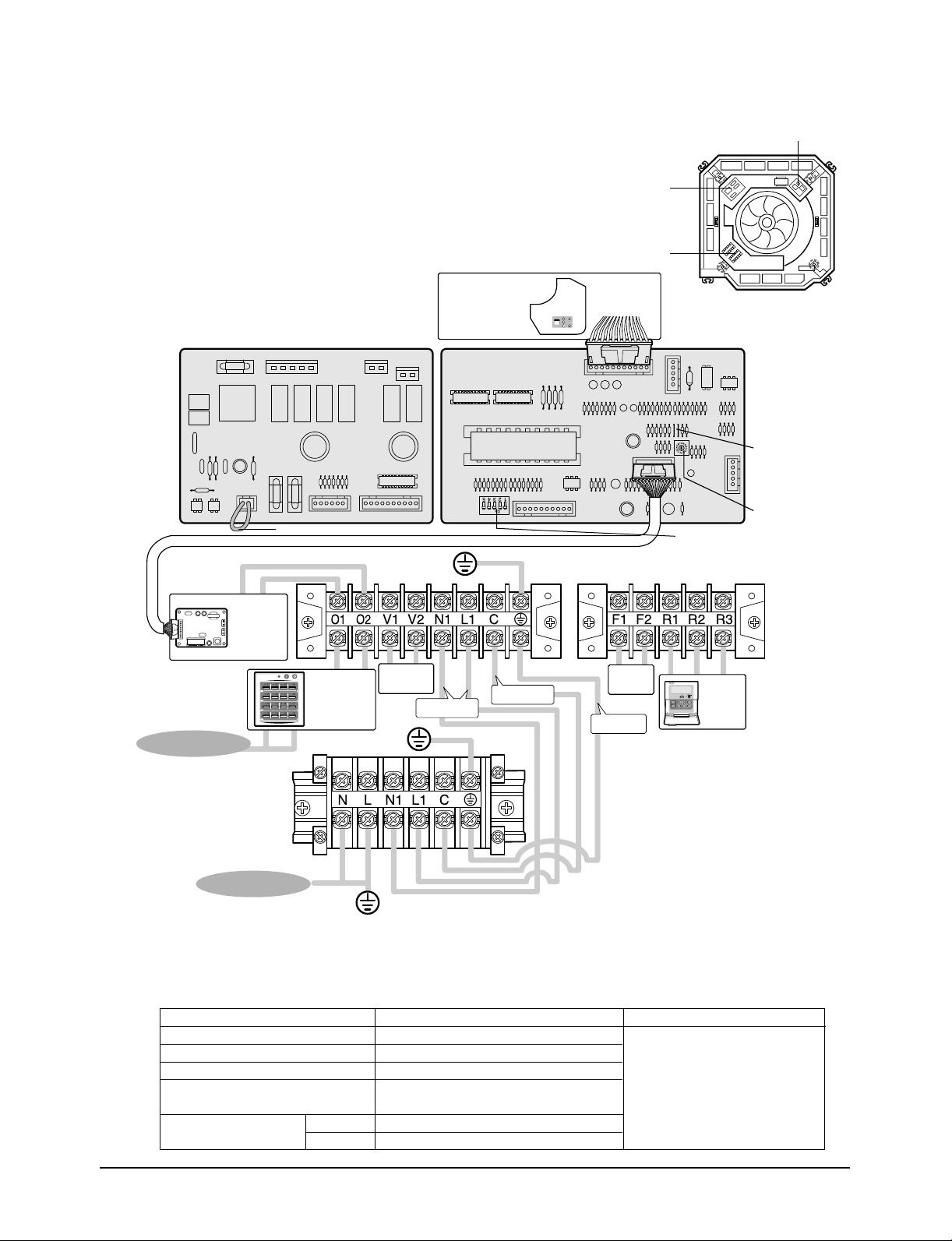
Installation
Wiring Diagram
SUB PCB MAIN PCB
CN20 Connector
Receiver & Display
Unit(Optional)
SW2
Sub PCB
Terminal block
CN9
CN7
SW1
DIP Switch
Indoor Unit
Main PCB
Jumper
Wire
Rotary
Digital
Switch
Transmitter
(Optional)
Centralized
Controller
(Optional)
Ventilator
Motor
Power
Communication
MAIN POWER
Outdoor Unit
MAIN POWER
Cable Specifications
The following electrical characteristics must be respected.
MODEL
Power
Sub switch
Fuse
Min. size of electric Wires
from/to the indoor/outdoor unit
Size of electric input wires
20m or less
50m or less
ACH1800E/2400E, CH18ZA/24ZA, CH18CA/24CA
1Ø - 220V-240V~, 50Hz
30A
30A
H07RN-F, 4G, 1.0mm
H07RN-F, 3G, 2.5mm
H07RN-F, 3G, 4.0mm
Float
Switch
EARTH
Wired
Remote
Controller
(Optional)
Note
The power cables are not
supplied with the air conditioner.
The user should purchase them
2
2
2
separately.
Samsung Electronics
4-23
Page 43

Installation
Wiring Diagram
Sub PCB
Terminal block
Receiver & Display
Unit(Optional)
SUB PCB MAIN PCB
CN9
CN7
SW1
Main PCB
Jumper
Wire
Transmitter
(Optional)
MAIN POWER
220-240V~, 50Hz
Cable Specifications
CN20 Connector
Centralized
Controller
(Optional)
Ventilator
Motor
SW2
Power
Communication
Outdoor Unit
Float
Switch
DIP Switch
Indoor Unit
Wired
Remote
Controller
(Optional)
Rotary
Digital
Switch
MAIN POWER
3Ø, 380-415V~, 50Hz
4-24
The following electrical characteristics must be respected.
MODEL
Power
Sub switch
Fuse
Min. size of electric Wires
from/to the indoor/outdoor unit
Size of electric input wires
20m or less
50m or less
ACH3600G/4400G, CH36ZA/44ZA, CH36CA/44CA
3Ø, 380V-415V~, 50Hz
30A
30A
H07RN-F, 4G, 1.0mm
H07RN-F, 3G, 2.5mm
H07RN-F, 3G, 4.0mm
2
2
2
Note
◆ The power cables are not
supplied with the air conditioner.
The user should purchase them
separately.
◆ When connecting the cables to
the main power, you should
connect each cable(L1, L2 &
L3) properly.
Samsung Electronics
Page 44

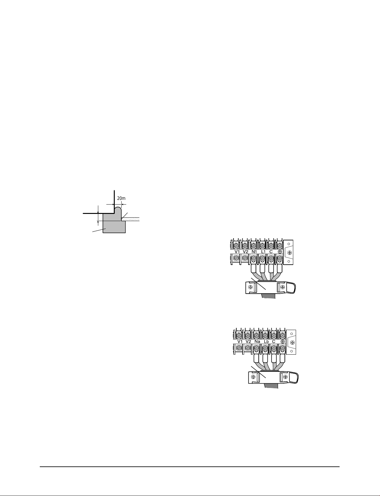
Installation
4-5-4 Connecting the Cables to the Outdoor
Unit
Two electric cables must be connected to the outdoor
unit.
• The connection cord connecting the indoor unit to
the outdoor unit
• The power cable connecting the auxiliary circuit
breaker to the outdoor unit
1. Remove the terminal board cover on the side of
the outdoor unit.
2. Connect the connection cord(L1, N1, C1, )
and power cable(N, L) to terminals as shown in
the diagram.
3. Connect the power cable to the auxiliary circuit
breaker.
An all pole disconnection from the power
supply must be incorporated in the fixed
wiring(≥3mm).
4. Replace the terminal board cover, carefully
tightening the screw.
Indoor Unit
EARTH
Power
Outdoor Unit
Communication
Power Cable
Auxiliary circuit
breaker
Wiring Diagram
Caution :
Keep the power cable and the connection cord in a steel pipe to
protect them against liquids, outside impacts and so on.
4-25Samsung Electronics
Page 45

Installation
Two electric cables must be connected to the outdoor
unit.
• The connection cord connecting the indoor unit to
the outdoor unit
• The power cable connecting the auxiliary circuit
breaker to the outdoor unit
1. Remove the terminal board cover on the side of
the outdoor unit.
2. Connect the connection cord (Na, Lb, C, )
and power cable(L1, L2, L3, N, ) to
terminals as shown in the diagram.
3. Connect the power cable to the auxiliary circuit
breaker.
An all pole disconnection from the power
supply must be incorporated in the fixed
wiring(≥3mm).
4. Replace the terminal board cover, carefully
tightening the screw.
Indoor Unit
Power
Wiring Diagram
Communication
EARTH
Outdoor Unit
Power Cable
Auxiliary circuit
breaker
Caution :
Keep the power cable and the connection cord in a steel pipe to
protect them against liquids, outside impacts
and so on.
Samsung Electronics4-26
Page 46

Installation
4-5-5 Checking Correct Grounding
If the power distribution circuit does not have an earth
or the ground does not comply with specifications, an
grounding electrode must be installed.
The corresponding accessories are not supplied with
the air conditioner.
1. Select an grounding electrode that complies
with the specifications given in the illustration.
Carbon
plastic
yellow wire, 2mm
2. Determine a suitable location for the grounding
electrode:
• In damp hard soil rather than loose sandy or
gravel soil that has a higher grounding
resistance
• Away from underground structures or
facilities, such as gas pipes, water pipes,
telephone lines and underground cables
• At least two metres away from a lightening
concassetteor grounding electrode and its
cable
Steel
core
PVC-insulated green/
2
x 3.5 m
Terminal M4
grounding
screw
To
3. Finish wrapping insulating tape around the rest
of the pipes leading to the outdoor unit.
4. Install a green/yellow coloured grounding wire
2
(Ø1.6 mm, section 2 mm
or greater):
• If the grounding wire is too short, connect an
extension lead, in a mechanical way and
wrapping it with insulating tape (do not bury
the connection)
• Secure the grounding wire in position with
staples
NOTE : ◆ If the grounding electrode is installed in an
area of heavy traffic, its wire must be
connected securely.
5. Carefully check the installation, by measuring
the grounding resistance with an ground
resistance tester. If the resistance is above
required level, drive the electrode deeper into
the ground or increase the number of grounding
electrodes.
6. Connect the grounding wire to the electrical
component box inside of the outdoor unit.
4-5-6 Drain Hose Installation
NOTE : ◆ The grounding wire for the telephone line
cannot be used to ground the air conditioner.
50cm
30cm
Samsung Electronics
Care must be taken when installing the drain hose for
the indoor unit to ensure that any condensate water is
correctly drained outside.
1. Insert the flexible hose
to the drain tube
outlet, if necessary.
NOTE : ◆ Attach the drain hose to the drain tube outlet
with the adhesives to prevent water leaks,
then secure the hose with a band etc..(The
band is not supplied with the air conditioner.)
Drain tube
outlet
4-27
Page 47

Installation
CCCCAAAAUUUUTTTTIIIIOOOONN
NN
Do not install air bleeding tubes, as this may
cause water to spray from the drain tube outlet.
Check that the indoor unit is level with the
ceiling by using the leveler.
If it is necessary to increase the height of the drain hose
somewhat, the portion directly after 30cm. If it is raised
higher than 50cm, there can be water leaks.
Air bleeder
Ceiling
300mm or less
1~1.5m
C
B
A
Do not give the hose and upward gradient after the
connection port.
This will cause water to flow backwards when
the unit is stopped, resulting in water leaks.
Do not apply force to the piping on the unit side when
connecting the drain hose. The hose should not be
allowed to hang loose from its connection to the unit.
Fasten the hose to a wall, frame or other support as
close to the unit as possible.
Upward gradient
Support pieces
1~1.5m
1/100 or more
Flexible hose
Band joint
Ceiling
Ceiling
Ceiling
✳✳18/✳✳24 ✳✳36/✳✳44
A
750 mm 750 mm
B 200 mm 258 mm
C 550 mm 482 mm
2. Install the drain hose so that its length can be as
short as possible. Internal diameter of the drain
hose should be the same or slightly bigger than
the external diameter.
• Inner diameter of the drain hose
Flexible hose is connected
32mm(Outer diameter)
Flexible hose is not connected
27mm(Outer diameter)
NOTE : ◆ Give a slightly slant to the drain hose for proper
drainage of condensate.
NOTE : ◆ Secure the drain hose with the band joint and the
cable-tie not to be separated from the unit.
Insulation drain sub
Indoor
Unit
Adhesives
Band(Not supplied)
Insulation drain pipe
Insulation cover drain
Caution :
Must fit tightly against body without any gap.
No gap
3. Wrap the drain hose with the insulation drain as
shown in figure and secure it.
NOTE : ◆ When connecting the drain hose without the
flexible hose, you should attach it to the drain
tube outlet with adhesives and tapes to
prevent water leaks.
Caution :
Samsung Electronics4-28
Page 48

Installation
Testing the drainage
You should test the drainage after completing the
installation.
Prepare a little water about 2.0 liter.
1. Remove two screws on the cover drain pump
and pull out the cover.
Cover drain pump
2. Pour water into the indoor unit as shown in
figure.
4-5-7 Connecting the Indoor Unit Assembly
Piping
There are two refrigerant pipes of differing diameters:
• Asmaller one(9.52mm, 3/8") for the liquid refrigerant
• Alarger one(15.88mm, 5/8") for the gas refrigerant
• The thickness of tube should not less than 1.0mm.
• The inside of copper tube must be clean & has no
dust.
The connection procedure for the refrigerant pipes
varies according to the exit position of the pipes from
the indoor unit, as seen when facing the indoor in the
"A" side.
• Liquid refrigerant port
• Gas refrigerant port
Liquid refrigerant port
A
Gas refrigerant
port
NOTE : ◆ If you do not pour water inside the water
supply intake, water may spill from the indoor
unit.
3. Confirm that the water flows out through the
drain hose.
NOTE : ◆ You can check the drainage only when the air
conditioner is turned on.
4. Reassemble the cover drain pump and the
screws.
1. Remove the protection caps
on the pipes and connect
the assembly pipes to each
pipe, tightening the nuts,
first manually and then
with a wrench, a spanner
applying the following
torque.
Outer Diameter Torque (kgf•cm)
19.52 mm (3/8") 300
15.88 mm (5/8") 750
Samsung Electronics
4-29
Page 49

Installation
90
O
2. Must use insulator which is thick enough to
cover more than 10mm the refrigerant tube to
protect the condensate water on the outside of
pipe falling onto the floor and the efficiency of
the unit will be better.
a. When the indoor unit is above the outdoor unit
Indoor unit
Outdoor unit
b. When the outdoor unit is above the indoor unit
Oil trap
(Must be installed every 6m)
Outdoor unit
7. For further details on connecting up to the
outdoor unit and purging the refrigerant circuit.
NOTE : ◆ For further details on connecting up to the
outdoor unit and purging the refrigerant circuit.
4-5-8 Cutting/Flaring the Pipes
Connect the pipe within 30m and cutting pieces will not
be gone into the pipe as being clean to pipe section
1. Make sure that you have the required tools
available (pipe cutter, reamer, flaring tool and pipe
holder).
Oil trap
(Must be installed every 6m)
Indoor unit
Radius
5cm
Oil trap
(suction tube)
3. Cut off any excess foam insulation.
4. Be sure that there must be no crack or wave on
the bended area.
5. It would be necessary to double the insulation
thickness to prevent condensation even on the
insulator when if the installed area is warm and
humid.
6. Shape an oil trap as shown in figure. The oil
trap must be formed every level difference of
6m.
2. If you wish to shorten the pipes, cut it with a
pipe cutter, taking care to ensure that the cut
edge remains at a 90° angle with the side of the
pipe. Refer to the illustrations below for
examples of edges cut correctly and incorrectly.
Oblique
Rough
Burr
3. To prevent any gas from leaking out, remove all
burrs at the cut edge of the pipe, using a reamer.
Samsung Electronics4-30
Page 50

Installation
4. Slide a flare nut on to the pipe and modify the
flare.
Outer Diameter(D) Depth (A)
19.52 mm (3/8") 1.8 mm
15.88 mm (5/8") 2.2 mm
19.05 mm (3/4") 2.2 mm
5. Check that the flaring is correct, referring to the
illustrations below for examples of incorrect
flaring.
Inclined
Cracked Uneven Thickness
Damaged Surface
4-5-9 Connecting the Drain Hose to the
Outdoor Unit
When using the air conditioner in the heating mode, ice
may accumulate. During de-icing, the condensed water
must be drained off safely. Consequently, you must
install a drain hose on the outdoor unit, following the
instructions below.
1. Make space more than 50mm between the
bottom of the outdoor unit and the ground for
installation of the drain hose, as shown in
figure.
50mm min.
2. Insert the drain plug into the hole on the
underside of the outdoor unit.
6. Align the pipes and tighten the flare nuts first
manually and then with a wrench, applying the
following torque.
Outer Diameter(D) Torque(kgf•cm)
19.52 mm (3/8") 300
15.88 mm (5/8") 750
19.05 mm (3/4") 750
7. For further details on how to connect up to
the outdoor unit and purge the circuit.
Caution :
In case of welding the pipe, you must weld with
nitrogen gas blowing.
3. Connect the drain hose to the drain plug.
[Drain hose: ID(18mm), Drain plug: OD(18mm)]
30mm
4. Ensure that the drained water runs off correctly
and safely.
Samsung Electronics
4-31
Page 51

Installation
4-5-10 Fixing the Unit in Position
The outdoor unit must be installed on a rigid and stable
base to avoid any increase in the noise level and
vibration, particularly if the outdoor unit is to be
installed close to a neighbour. If it is to be installed in a
location exposed to strong winds or at a height, the unit
must be fixed to an appropriate support (wall or ground).
1. Position the outdoor unit so that the air flow is
directed towards the outside.
2. Attach the outdoor unit to the appropriate
support using anchor bolts.
A
B
Capacity A B
UBH1800E, CH18ZAX, CH18CAX 582mm 340mm
UBH2400E, CH24ZAX, CH24CAX 660mm 340mm
UCH3600G, UCH4400G
CH36ZAX, CH44ZAX 840mm 415mm
CH36CAX, CH44CAX
3. If the outdoor unit is exposed to strong winds,
install shield plates around the outdoor unit, so
that the fan can operate correctly.
Samsung Electronics4-32
Page 52

• Use the vacuum pump to remove N2 gas or air inside the indoor unit and pipes.
Installation
1. Tighten all pipe connections (A, B, C, D)
to prevent any leakage.
2. Check that the suction and liquid valves are
turned off clockwise to close the outdoor unit.
3. Remove the cap on the opposite side of the
Suction tube connection (A) and connect a hose
from the pressure guage of which other end is
connected to the vacuum pump.
4. Operate the vacuum pump enough until the
pressure guage indicates “0”.
Liquid
Valve
3-way valve
Suction
Valve
For mounting
other end of
hose when
not in use
Suspension hook
Finger tight
fittings
Connected to
high pressure
side
Charging
line
Vacuum pump
High
pressure
gauge
Hand
wheel
5. Disconnect the hose from the suction valve
cafully not to break the vacuum.
6. Turn on the suction and liquid valves
counterclockwise to open the outdoor unit to the
indoor unit.
7. Check the leakage on the connections.
(A, B, C, D)
8. Check each valve for leakage.
Indoor Unit
Half union
DC
Liquid
pipe side
Liquid
valve
Suction(gas)
pipe side
Suction(gas)
valve
BA
Outdoor Unit
Samsung Electronics
4-33
Page 53

Installation
4-5-11 Refrigerant Refill Procedure
1. Refrigerant Refill
•Refill the air-conditioner with refrigerant when the refrigerant has leaked during the installing or using
1. Turn the suction valve clockwise to close,
connect the pressure gauge(low
pressure side) to the service valve, and
open the suction valve again.
Suspension hook
2. Connect the tank to refill with Refrigerant
3. Set the unit to cool operation mode.
4. Check the pressure indicated by the
pressure gauge(low pressure side).
*Standard pressure should be
4.5~5.5kg/cm2in a regular, operation
mode.
5. Open the refrigerant tank and fill with
refrigerant until the rated pressure is
reached.
*It is recommended not to pour the
refrigerant in too quickly, but gradually
while operating a pressure valve.
Liquid
Valve
3-way valve
Suction
Valve
For mounting
other and of
hose when
not in use
High
pressure
gauge
Hand
wheel
Finger tight
fittings
Connected to
high pressure
side
Charging
line
4-34
6. Stop operation of the air conditioner.
7. Close the suction valve, disconnect the
pressure gauge, and open the suction
valve again.
8. Close the cap of each valve.
Caution :
• You must not add the R407C refrigerant without purging
and vacuum procedure.
Samsung Electronics
Page 54
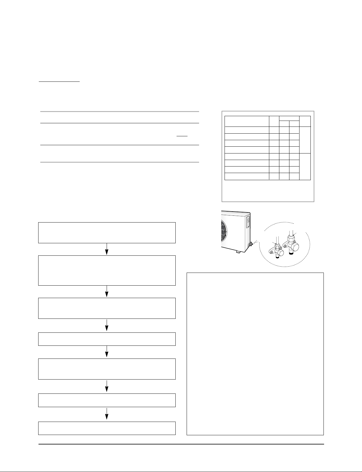
Installation
2. Refrigerant Adjustment (Supplement)
Adding Refrigerant
Refrigerant must be added if the piping measures more than 5 metres in length (maximum of “A” metres). The quantity of
additional refrigerant is variable according to the installation situation. Thus, make sure the outdoor unit situation before adding
refrigerant. This operation can only be performed by a qualified refrigeration specialist.
☛ If you have used... Then...
More than 5 metres “B”g of refrigerant (“C”)
of the pipes must be added for each
extra metre.
Less than 5 metres The purge time is normal.
of piping
4-5-12 “Pump down” Procedure
• ’Pump down’ shall be carried out when an
evaporator replaced or when the unit is relocated in
another area.
1. Remove the caps from the liquid valve and the suction
valve.
2. Turn the suction valve clockwise to close and connect
a pressure gauge(low pressure side) to the service
valve, and open the suction valve again.
Type
ACH1800E, CH18ZA
ACH2400E, CH24ZA
ACH3600G, CH36ZA
ACH4400G, CH44ZA
CH18CA
CH24CA
CH36CA
CH44CA
For details about the installation
situation(a or b)
❋ refer to 4-30 page
AC
30
30
50
50
30
30
50
50
Suction
valve
Relocation of the Air Conditioner
B
ab
50
40
50
40
45
60
35
50
50
50
50
40
40
45
40
40
Liquid
valve
R-22
R407C
3. Set the unit to cool operation mode.
(Check if the compressor is operating.)
4. Turn the liquid valve clockwise to close.
5. When the pressure gauge indicates “0” turn the
suction valve clockwise to close.
6. Stop operation of the air conditioner.
7. Close the cap of each valve.
Samsung Electronics
• Refer to this procedure when the unit is relocated.
1. Carry out the pump down procedure (refer to the
details of ‘pump down’).
2. Remove the power cord.
3. Disconnect the assembly cable from the indoor and
outdoor units.
4. Remove the flare nut connecting the indoor unit
and the pipe.
5. Disconnect the pipe connected to the outdoor unit.
At this time, cover the valve of the outdoor unit
and the other pipe using a cap or vinyl plug to
prevent foreign material from entering.
6. Make sure you do not bend the connection pipes in
the middle and store together with the cables.
7. Move the indoor and outdoor units to a new
location.
8. Remove the mounting plate for the indoor unit and
move it to a new location.
4-35
Page 55

Installation
4-5-13 Performing Leak Tests
Before completing the installation (insulation of the hose and piping),
you must check that there are no gas leaks.
To check for gas leaks on the... Then, using a leak detector,
check the...
Indoor unit Flare nuts at the end of sections A
and B.
A
B
Outdoor unit Valves on sections C and D.
Caution :
• The CH✴✴CAmodels need a new refrigerant, R407C.
Thus, when refrigerant leakage occurs in use, you must purge and make
vacuous with a vacuum pump before adding the refrigerant.
Then put the optimal quantity of refrigerant newly.
In addition, the refrigerant must be added in liquid phase.
D
C
4-36 Samsung Electronics
Page 56

Installation
4-5-14 Installing the Front Panel
1. Open the electrical component box cover
removing the screws.
2. Connect the cables of the front panel to the PCB
as shown in figure.
Front Panel
3. Close the electrical component box cover and
secure the screws.
Front panel fixing holes
Eye
5. Secure the front panel to the indoor unit using
the bolts(4EA). HEX ; M6 x L30
Air blocking
kit
NOTE : ◆ When user’s optional accessory is a wireless
remote controller, you have to install the
receiver & display unit.
NOTE : ◆ There are four kinds of air blocking kits. Fill
up the air outlet(s) with one or more kits
depending on the situation, then install the
insulation to block air completely.
NOTE : ◆ After removing the cushion Blocking that
is installed in the air outlet of
ACH3600G/4400G and CH36ZA/44ZA
to install the air blocking.
4. Install the front panel using two hooks on the
both sides of the indoor unit.
Hook and Eye
Samsung Electronics
4-37
Page 57

Installation
4-5-15 Setting Up Option Switches
IMPORTANT : Before setting up the option switches, always make sure that you have turned off the main power.
Main PCB in the Indoor Unit
Rotary Digital Switch(SW1)
A user can operate up to sixteen air conditioners by using the wired remote
controller. Before controlling more than one air conditioner, you should connect
the air conditioner each other. And you must assign addresses to the air
conditioners. For further details on connecting air conditioners.
If the user would like to controller only one air conditioner, make sure that the
arrow is at “0” position.
Turn the arrow to the desired position referring to the table below.
Switch No.
0
1
2
3
4
5
6
7
Number of
indoor unit(s)
One
Two
Three
Four
Five
Six
Seven
Eight
Switch No.
8
9
A
B
C
D
E
F
Number of
indoor unit(s)
Nine
Ten
Eleven
Twelve
Thirteen
Fourteen
Fifteen
Sixteen
DIP Switch(SW2)
Adjust the switch to the desired position referring to the table below.
Switch
No.
1
2
3
4
5
Option Item
Ventilator Fan
Drain Pump
Float Switch
Filter Cleaning Cycle
Indoor Fan Motor Speed
Note : ◆ Make sure that the No.2 and No.3 switches are at “ON” position.
Switch Position
ON OFF
Not installed
Installed
Installed
1,000 hours
Normal
Installed
Not installed
Not installed
2,000 hours
High speed
Note
Not supplied
Samsung Electronics4-38
Page 58

4-5-16 Setting Up Option Switches (Cont.)
Jumper Wire(SW05)
You can adjust the setting temperature for heating. Cut off the SW05,
depending on the situation.
Option Item Situation of the Switch Note
Installation
Setting temperature +2°C
Setting temperature +5°C
Short
Open
Preset Position
Sub PCB in the Indoor Unit
CN20 Connector
Remove the CN20 connector in the sub PCB, if necessary, referring to the
table below. (This procedure is needed only when the user would like to
control a group by using the wired remote controller.)
Address Situation of the CN20 Connector
0
1 - F
Note : ◆ Up to 16 air conditioners can be controlled with one wired remote
controller.
Note : ◆ If the user does not want to control a group, do not remove the
CN20 Connector.
Connected
Removed
Unit A
(Address 0)
CN20 Connector
Unit B
(Address 1)
Unit C
(Address 2)
Sub PCB in the Indoor Unit
Dip Switch(DS01)
Adjust the DIP switch No.2 and/or No.4 to the desired position referring to
the table below. You must not adjust the switch 1 and 3. They should be in
“OFF” position at all times.
Switch
No.
Number of air conditioner(s) controlled
2
by the wired remote controller
Using wireless remote controller
4
Samsung Electronics
Option Item
Switch Position
ON OFF
Group
controlling
Can be used
One indoor unit
controlling
Cannot be used
4-39
Page 59
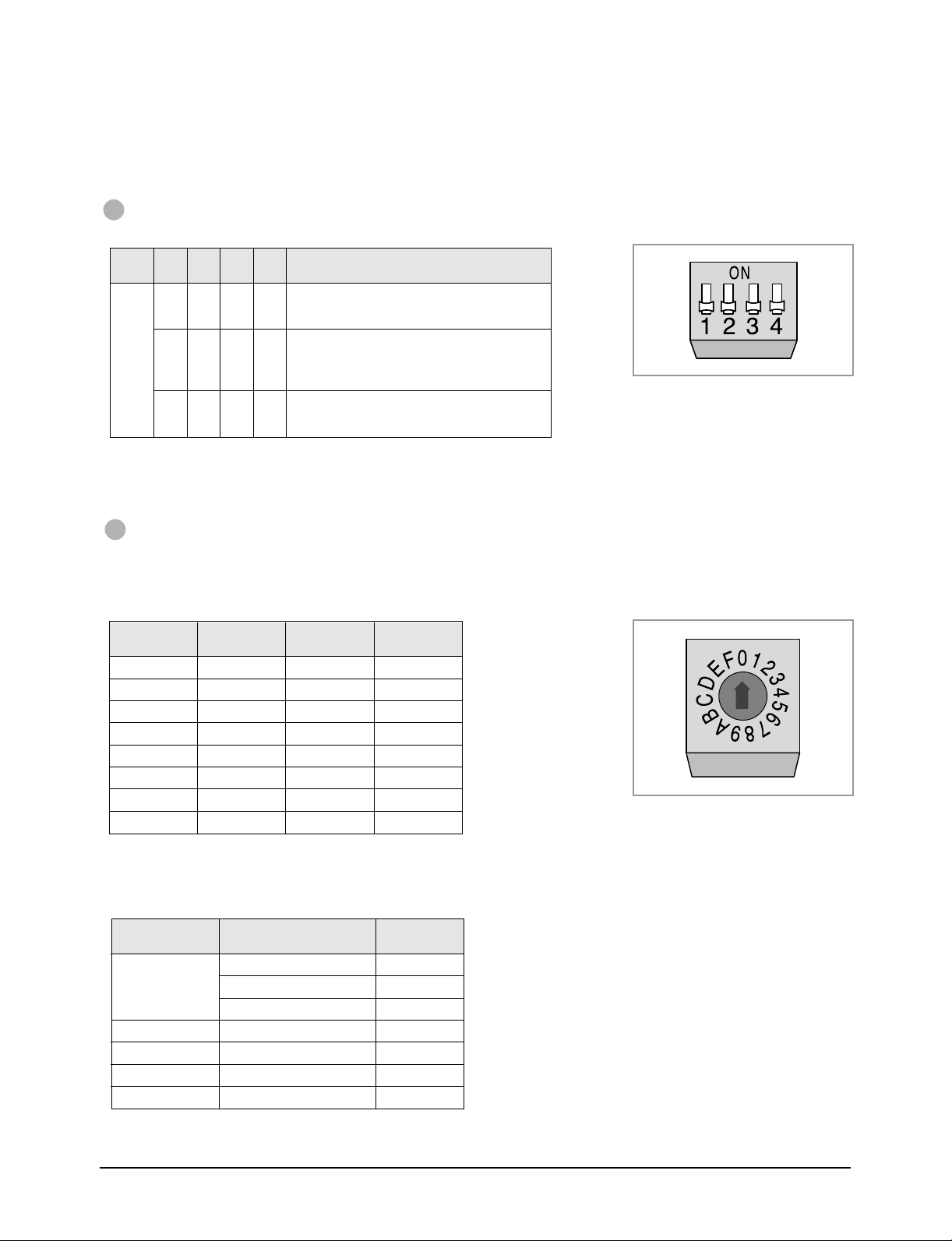
Installation
Centralized Controller
DIP Switch(DS01)
Adjust the DIP switch to the desired position referring to the table below.
Switch
Switch
Position
Note : ◆ You cannot install the centralized controller when the wired remote controller for a group has already been installed.
1234 Meaning
No.
OFF
OFF
OFF
OFF
OFF
OFF
OFF
OFF
ON
The air conditioner is operated by the controller
OFF
adjusted last among the wired remote controller,
wireless remote controller and centralized controller.
A user can use wired/wireless remote controller when
the centralized controller is switched on.
ON
And he/she cannot use the remote controller(s) when
the centralized controller is switched off.
The air conditioner(s) can be controlled by only the
OFF
centralized controller. The user cannot use the
wired/wireless remote controller in this case.
Transmitter
Rotary Digital Switch(DS01)
A user can turn on/off up to sixteen air conditioners by using the centralized controller. To use the controller, you
must assign addresses to the air conditioners. For further details on connecting air conditioners.
If the user would like to controller only one air conditioner, make sure that the arrow is at “0” position.
Turn the arrow to the desired position referring to the table below.
Switch No.
0
1
2
3
4
5
6
7
Number of
indoor unit(s)
One
Two
Three
Four
Five
Six
Seven
Eight
Switch No.
8
9
A
B
C
D
E
F
Number of
indoor unit(s)
Nine
Ten
Eleven
Twelve
Thirteen
Fourteen
Fifteen
Sixteen
Original Position of Option Switches
The option switches are preset by the manufacturer. Refer to the table below, if necessary.
Option Place
Main PCB in the
indoor unit
Sub PCB in the indoor unit
Wired Remote Controller
Centralized Controller
Transmitter
Note : ◆ Before setting up the options, always make sure that you have switched off the main power.
Note : ◆ After adjusting the options, you should supply the power. Otherwise, the options will not be applied.
Component No. State
Rotary Digital Switch(SW1)
DIP Switch(SW2)
Jumper Wire(SW05)
CN20 Connector
DIP Switch(DS01)
DIP Switch(DS01)
Rotary Digital Switch(DS01)
0
ON
SHORT
Connected
ALL OFF
ALL OFF
0
Samsung Electronics4-40
Page 60

Installation
4-5-17 Wired Remote Controller Installation
(Optional)
Accessories
Wired Remote
Controller(1)
KR-H50210
1. Disassemble the wired remote controller by
using two grooves on the top of it.
2. Secure the rear cover of the wired remote
controller on the wall with two screws.
3. Connect the R1, R2 and R3 terminals in the
wired remote controller to the R1, R2 and R3
terminals on the electrical component box each.
Cable-Tie(2) Cable Clamp(5) M4 X 16 Tapped
Screw(7)
Caution :
• Do Not keep the wired remote controller cables with a
220V cable because the remote controller cables have
low voltage.
• Do Not input 220V power to the R1, R2 and R3 in the
wired remote controller.
Note : Cable Specifications
Cable type
Size of cables
Max. length of electric wires from
the indoor unit to the wired remote
controller
Double-insulation, 3G
0.3mm2~0.75mm
100m
4. Reassemble the wired remote controller.
Caution :
• The optional kits must be installed by an installation
specialist.
• Before installing the optional kits, ensure that you have
turned off the main power.
• All optional kits cables should be installed according to
the national wiring rules and you must install them in the
wall not to be touched by users.
2
Samsung Electronics
Indoor Unit
Wired
Remote
Controller
4-41
Page 61

Installation
4-5-18 Centralized Controller Installation
(Optional)
Accessories
Centralized
Controller(1)
KR-H60110
Transmitter(1)
KT-A00
Cable-Tie(2) Cable Clamp(5) M4 X 16 Tapped
Screw(7)
Spacer Support(4) Cable-Tie(2) M4 X 16 Tapped
Screw(7)
1. Open the centralized controller cover by using
two grooves on the top of it.
5. Connect the O1 and O2 terminals of the
centralized controller to the O1 and O2
terminals on the electrical component box as
shown in figure.
Caution :
•Do NOT keep the centralized controller cables with a
220V cable because the centralized controller cables have
low voltage.
2. Secure the rear cover of the centralized
controller on the wall with two screws.
3. Secure the transmitter with four spacer supports
into the electrical component box.
Electrical component box
Sub PCB
Transmitter
Main PCB
4. Connect the cable from the PCB to the
transmitter.
And connect another cable from the O1, O2
terminals to the transmitter as shown in figure.
MAIN POWER
Note : Cable Specifications
Cable type
Size of cables
Max. length of electric wires from
the indoor unit to the centralized
controller
Centralized
Controller
Double-insulation,
2G(Shield Cable)
0.75mm2~1.25mm
1km
Samsung Electronics4-42
2
Page 62
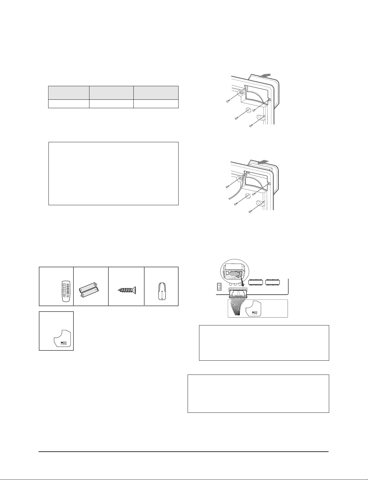
Installation
6. Connect the power cables.
Note : Cable Specifications
Cable type
Size of cables 0.75mm2~1.25mm
Double-insulation,
2G
Power Supply
2
220V-240V~, 50Hz
7. Reassemble the centralized controller.
Caution :
•The optional kits must be installed by an installation
specialist.
•Before installing the optional kits, ensure that you have
turned off the main power.
•All optional kits cables should be installed according to
the national wiring rules and you must install them in the
wall not to be touched by users.
4-2-19 Receiver & Display Unit Installation
(Optional)
Accessories
2. Remove the part of the front panel.
3. Secure the receiver & display unit with the
screws.
4. Connect the end of the connector wire to the
receiver & display unit and connect the other
end of the wire to the electrical component box
as shown in figure.
Wireless Remote
Controller(1)
KR-H40200
Receiver &
Display Unit(1)
(KRE-H1000)
Battery(2) M4 X 16 Tapped
Screw(2)
Remote Controller
Holder(1)
In case of using the wireless remote controller, you must
install the receiver & display unit to the front panel
before fixng the panel.
1. Disassemble three screws on the place where
you would like to install the receiver & display
unit, inside the front panel.
Receiver
& Display
Unit
Caution :
•Do NOT keep the wired remote controller cables with a
220V cable because the remote controller cables have
low voltage.
Caution :
•Optional kits must be installed by an air conditioner specialist.
•Before installing the optional kits, ensure that you have turned
off the main power.
Samsung Electronics
4-43
Page 63

Installation
4-5-20 Bio-Pure Filter Installation (Optional)
The air conditioner can be fitted with a Bio-Pure filter to
remove minute dust particles. The service life of the
filter is approximately three months depending on the
time during which the air conditioner is used.
1. Remove the vinyl packing from the filter.
Note : Do not remove the packing from a bio-pure filter
until you wish to use the filter, as it will lose its
properties.
2. Open the front grille by pulling the tabs on the
grille.
3. Remove the safety clips to open the grille
completely.
4. Pull out the air filter.
5. Locate the bio-pure filter on the center of the air
filter.
6. Secure the bio-pure filter with four screws.
7. Reinstall the filter and the front grille.
Samsung Electronics4-44
Page 64

4-5-21. Controlling a Group
* You should adjust the option switches in the electrical component box or on the PCB of the wired remote
controller.
* Before setting up the option switches, always make sure that you have turned off the main power.
* After adjusting the options, you should supply the power. Otherwise, the options will not be applied.
With Wired Remote Controller
Installation
1. Connect the R1, R2 and R3 terminals in the wired remote
controller to the R1, R2 and R3 terminals in any indoor unit
“A” each.
2. Connect the R1 and R3 terminals in the indoor unit “A” to the
R1 and R3 terminals in another indoor unit “B”.
Caution :
When connecting the cables, you must keep these :
• The R1 terminals must be connected to the R1s.
• The R3 terminals must be connected to the R3s.
• Do not connect the R2 terminals to anywhere.
If you connect R2 terminals, the PCB will be damaged.
3. Connect the R1 and R3 terminals of “B” to any indoor unit
“C” and connect the others as the same way.
4. Adjust the rotary digital switch in the main PCB to the desired
position referring to the table below.
Switch No.
0
1
2
3
4
5
6
7
Number of
indoor unit(s)
One
Two
Three
Four
Five
Six
Seven
Eight
Switch No.
8
9
A
B
C
D
E
F
Number of
indoor unit(s)
Nine
Ten
Eleven
Twelve
Thirteen
Fourteen
Fifteen
Sixteen
Unit A
Unit B
Unit C
CN20 Connector
5. Remove the CN20 connectors on the sub PCBs except the unit
connected with remote controller(Address 0).
6. Adjust the DIP switch No. 2 in the wired remote controller to
“ON” position.
Note : You cannot install the centralized controller when the wired remote
controller for a group has already been installed.
Samsung Electronics
4-45
Page 65

Installation
With Centralized Controller
A user can turn on/off up to sixteen air conditioners by using the centralized controller.
In this case, the user can turn on/off all air conditioners or a specific air conditioner connected with the centralized
controller. And each air conditioner can be controlled by its own remote controller(s) depending on the setting.
1. Connect the O1 and O2 terminals in the centralized controller to
the O1 and O2 terminals in the indoor unit “A”.
2. Connect the O1 and O2 terminals in the indoor unit “A” to the
O1 and O2 terminals in another indoor unit “B”.
3. Connect the O1 and O2 terminals of “B” to any indoor unit “C”
and connect the others as the same way.
4. Adjust the DIP switch(DS01) in the centralized controller to the
desired position referring to the table below.
Switch
Switch
Position
1234 Meaning
No.
OFF
OFF
OFF
OFF
OFF
OFF
OFF
OFF
ON
The air conditioner is operated by the controller
OFF
adjusted last among the wired remote controller,
wireless remote controller and centralized controller.
A user can use wired/wireless remote controller when
the centralized controller is switched on.
ON
And he/she cannot use the remote controller(s) when
the centralized controller is switched off.
The air conditioner(s) can be controlled by only the
OFF
centralized controller. The user cannot use the
wired/wireless remote controller in this case.
Centralized
Controller
Unit A Unit B Unit C
5. Adjust the rotary digital switch on the transmitter to the desired
position referring to the table on page 4-40.
Centralized
controller
Note : You cannot install the centralized controller when the wired remote controller for a group has already been installed.
Samsung Electronics4-46
Page 66

Installation
4-5-22. Checking and Testing Operations
To complete the installation, perform the following
checks and tests to ensure that the air conditioner is
operating correctly.
Review all the following elements in the installation:
◆ Piping connection tightness to detect any gas
leakages
◆ Connecting wiring
◆ Heat-resistant insulation of the piping
◆ Drainage
◆ Earthing wire connection
◆ Correct operations(follow the steps below)
Wired Remote Controller
1. Supply the power and switch on the air
conditioner.
Note : If the air conditioner does not work because of
switching off the thermistor sensor caused by the
room temperature, you can operate the air
conditioner by using Test button.
Wireless Remote Controller
1. Supply the power and switch on the air
conditioner.
2. Remove the remote controller batteries.
3. Insert the batteries pressing the On Timer and
Off Timer buttons at the same time.
2. Press Test button more than 3 seconds without
selecting any mode.
: The air conditioner runs in COOL mode
Result
for 3 minutes.
Note : If the error code is displayed, fix the error.
And supply the power, restart testing.
3. Check that user's option(s) and the outdoor unit
operate properly.
Note : Do not attempt to select the operating mode or to
adjust the temperature. It may switch the outdoor
unit off.
4. Press the Swing( ) button and check that the
air flow blades work properly.
5. The air conditioner will switch it off
automatically after 3 minutes.
4. Stop pressing the buttons after inserting the
batteries.
5. Press the (ON/OFF) button.
Result:
The air conditioner runs in COOL mode
for 3 minutes.
6. Check that user ’s option(s) and the outdoor unit
operate properly.
Note : Do not attempt to select the operating mode or to
adjust the temperature. It may switch the outdoor
unit off.
7. Press the Swing( ) button and check that the
air flow blades work properly.
8. The air conditioner will switch it off automatically after 3 minutes.
Samsung Electronics
4-47
Page 67

Installation
4-5-23. Troubleshooting
Wired Remote Controller
If the error occurs, and the error code are displayed on the wired remote controller.
The error code blinks for 5 seconds and it disappears. If you would like to see the error code after disappearing it,
press the Test button.
Meaning of Error Code
The error code is composed of two-digit figures or letters. The first means (∗) an indoor unit address and the second
means an error code.
Error Code
∗
1 Indoor unit thermistor sensor error
∗
5 Indoor unit pipe sensor error
∗
6 Outdoor unit thermistor sensor error
∗
9 Float switch error
∗
A A Indoor and Outdoor
communication error
∗
C Wired remote controller communication
error
∗
D
Outdoor pipe sensor error
Meaning
Checking area
◆ Indoor unit thermistor sensor
◆ PCB of the indoor unit
◆ Indoor unit pipe sensor
◆ PCB of the indoor unit
◆ Outdoor unit thermistor sensor
◆ PCB of the outdoor unit
◆ Drain pump, Float switch
◆ Drain system
◆ DIP switch(SW2) of the indoor unit
(The No.2 and No.4 switches must
be at “ON” postion.)
◆ Communication cables of indoor and
outdoor units
◆ PCB of indoor and outdoor units
◆ Wired remote controller cables, Wired
remote controller
◆ Main/Sub PCB of the indoor unit
◆ Outdoor pipe sensor
◆ PCB of the outdoor unit
∗
L
Example : “39” means the address “3” indoor unit has a trouble with a float switch.
Three phase power incorrect
connecting error(In case of three
phase power models)
◆ Three phase power connecting
◆ PCB of the outdoor unit
Samsung Electronics4-48
Page 68

Wireless Remote Controller
If the error occurs, the indicators on the receiver & display unit displays the error.
Meaning of Error Code
Installation
Indicators
Timer
Operating
▲
▲▲
Filter
▲
▲▲
Indoor unit thermistor sensor error
Indoor unit pipe sensor error
Outdoor unit thermistor sensor error
Float switch error
Indoor and Outdoor communication
error
Wireless remote controller
communication error
Outdoor pipe sensor error
Three phase power incorrect
connecting error(In case of three phase
power models)
Meaning
Checking area
◆ Indoor unit thermistor sensor
◆ PCB of the indoor unit
◆ Indoor unit pipe sensor
◆ PCB of the indoor unit
◆ Outdoor unit thermistor sensor
◆ PCB of the outdoor unit
◆ Drain pump, Float switch
◆ Drain system
◆ Communication cables of indoor and
outdoor units
◆ PCB of indoor and outdoor units
◆ Wireless remote controller cables,
Wireless remote controller
◆ Main/Sub PCB of the indoor unit
◆ Outdoor pipe sensor
◆ PCB of the outdoor unit
◆ Three phase power connecting
◆ PCB of the outdoor unit
: OFF : Blinking : Blinking at once : Blinking alternately
▲▲
Samsung Electronics
4-49
Page 69

MEMO
4-50 Samsung Electronics
Page 70

5. Disassembly and Reassembly
Stop operation of the air conditioner and remove the power cord before repairing the unit.
Indoor Unit
No. Part name Procedures Picture
Front Grille & Filter 1. Open the front grille by pushing the tabs
!
on the grille.
IMPORTANT
You must give attention when disassembling
the front grille and must check the safety clips
have been installed. If you don't ensure them,
the front grille will drop suddenly and you will
be hurt.
2. Remove the front grille.
2-1. Remove the safety clips.
2-2. Open the front grille about 45˚ and
pull it forward.
Samsung Electronics
3. Pull out the filter air.
Safety Clip
5-1
Page 71
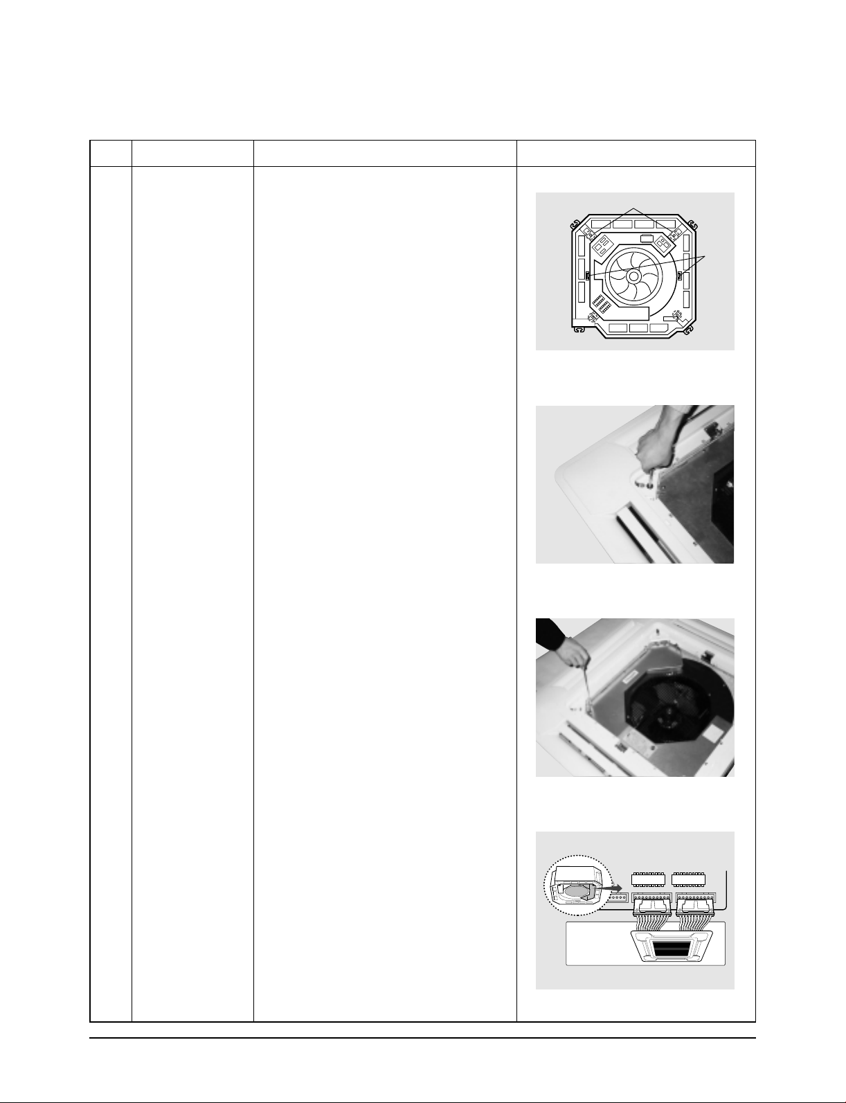
Disassembly and Reassembly
No. Part name Procedures Picture
4. Slowly loosen the four bolts holding the
panel to the assembly.
Front panel fixing holes
Eye
5. Open the electrical component box cover
removing the screws. (3EA)
6. Disconnect the two cables between the
assembly and the panel.
- Stepping motor connectors.
6-1. Disconnect the three cables between
the assembly and the panel.
- Stepping motor connector
- Receiver & Display unit connector
(Optional)
Front Panel
5-2
Samsung Electronics
Page 72
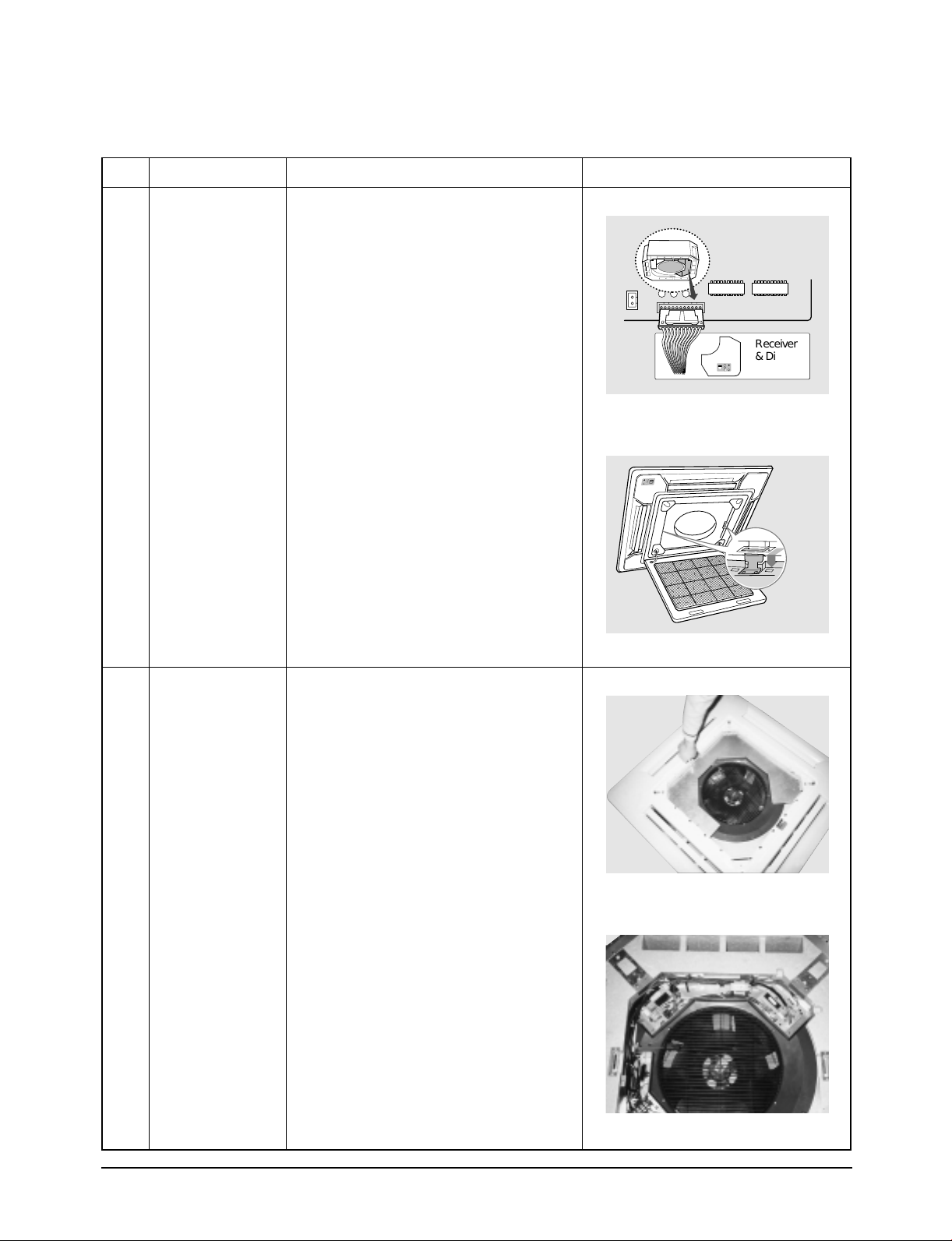
Disassembly and Reassembly
No. Part name Procedures Picture
<*Optional>
7. Separate the front panel using two hooks
on the both sides of the indoor unit.
Receiver
& Display
Unit
@
Electronic part
Hook and Eye
Do !-1, !-2, !-3 and !-4 above
1. Remove the screws(6EA) on the electrical
component box and remove the cover
plates.
2. Open the control box.
Samsung Electronics
5-3
Page 73

Disassembly and Reassembly
No. Part name Procedures Picture
3. Disconnect the other end of the cable to
the outdoor unit through the ceiling & the
hole on the wall between the control box
and the assembly.
#
Method 1
Fan and motor
Do !above
1. Disconnect FAN MOTOR wire
connector, thermistor wire
connector, drain pump wire connector.
2. Disconnect wire connects to capacitor.
5-4
Samsung Electronics
Page 74
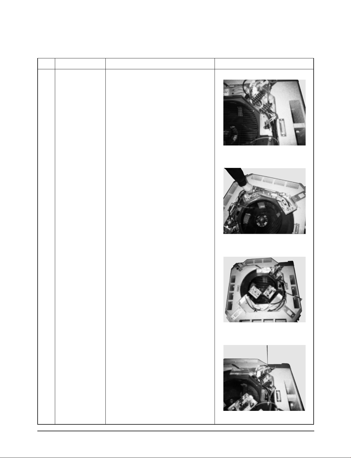
Disassembly and Reassembly
No. Part name Procedures Picture
Fan and motor 3. Disconnect float switch wire connected to
terminal board (F1, F2).
4. Disconnect all connectors connected to
PCB.
5. Remove PCB’s from assy case PCB.
6. Remove the screws(9EA) for disconnection
of Bell mouth and cushion drain.
Samsung Electronics
5-5
Page 75

Disassembly and Reassembly
No. Part name Procedures Picture
Fan and motor
Pump
5-6
Samsung Electronics
Page 76

Disassembly and Reassembly
No. Part name Procedures Picture
Pump
Samsung Electronics
5-7
Page 77

Disassembly and Reassembly
No. Part name Procedures Picture
Fan and motor 7. Seperate Bell mouth and Box Ass’y from
cushion drain.
8. Loosen the nut and separate the assy
holder fan.
9. Lift down carefully the Ass'y fan.
5-8
Samsung Electronics
Page 78

Disassembly and Reassembly
No. Part name Procedures Picture
Fan and motor 10.Separate the motor connector wire and
separate the wire holder fixed the bottom
floor.
11.Remove the screw fixed onto the bracket
wire fixed on the bottom of product and
remove screw fixed noto earth wire and
separate carefully the ass'y motor in from
the product after separation of nut of ass'y
motor in and grommet mount motor.
Samsung Electronics
5-9
Page 79

Disassembly and Reassembly
No. Part name Procedures Picture
Fan and motor
$
Method 2.
Pump
❈ Do #-1, 2, 3 above
1. For separation of Ass'y cushion drain from
the main body
! Cabinet guide A (2EA)
@ Cabinet guide B (1EA)
# Remove each cabinet power cord.
$
Remove the obstacles of pump drain
and ass'y sensor float wire due to the
movement of BKT wire.
5-10
Samsung Electronics
Page 80
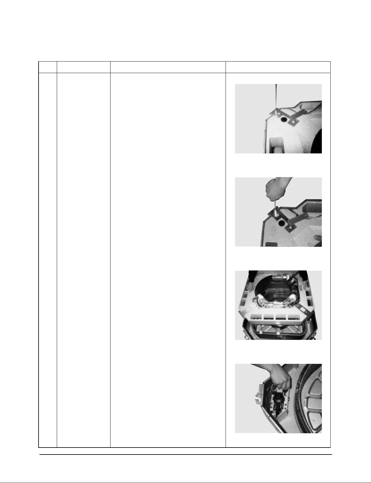
Disassembly and Reassembly
No. Part name Procedures Picture
Pump 2. For the separation of ass'y cushion drain
form the main body, remove the fixing
screw of bracket at each corner of cushion
drain.
3. Take out the CAP drain socket inserted in
the ass'y drain cushion to remove the
condensate in the drain cushion.
* Care must be taken for the taking out
the condensate water.
4. Lift down carefully the Ass'y cushion drain
from the main body.
5. Loosen three screws fixing the pump
drain.
Samsung Electronics
5-11
Page 81

Disassembly and Reassembly
No. Part name Procedures Picture
Pump
6. Separate the hose drain inserted in the
outlet of pump drain.
7. Separate from the BKT pump the pump
drain separated from the main body from
the BKT pump.
%
Heat exchanger
❈ Do $-1 ~ $-4
1. Separate the cover pipe at the side of
main body from main body.
2. Separate the partition front evap fixing the
heat exchanger to the base of main body.
5-12
Samsung Electronics
Page 82

Disassembly and Reassembly
No. Part name Procedures Picture
3. Separate the holder evap (2 EA) fixing the
heat exchanger to the base of main body.
4. Separate holder guide evap (4 EA).
5. Lift up the heat exchanger from the main
body.
Samsung Electronics
5-13
Page 83
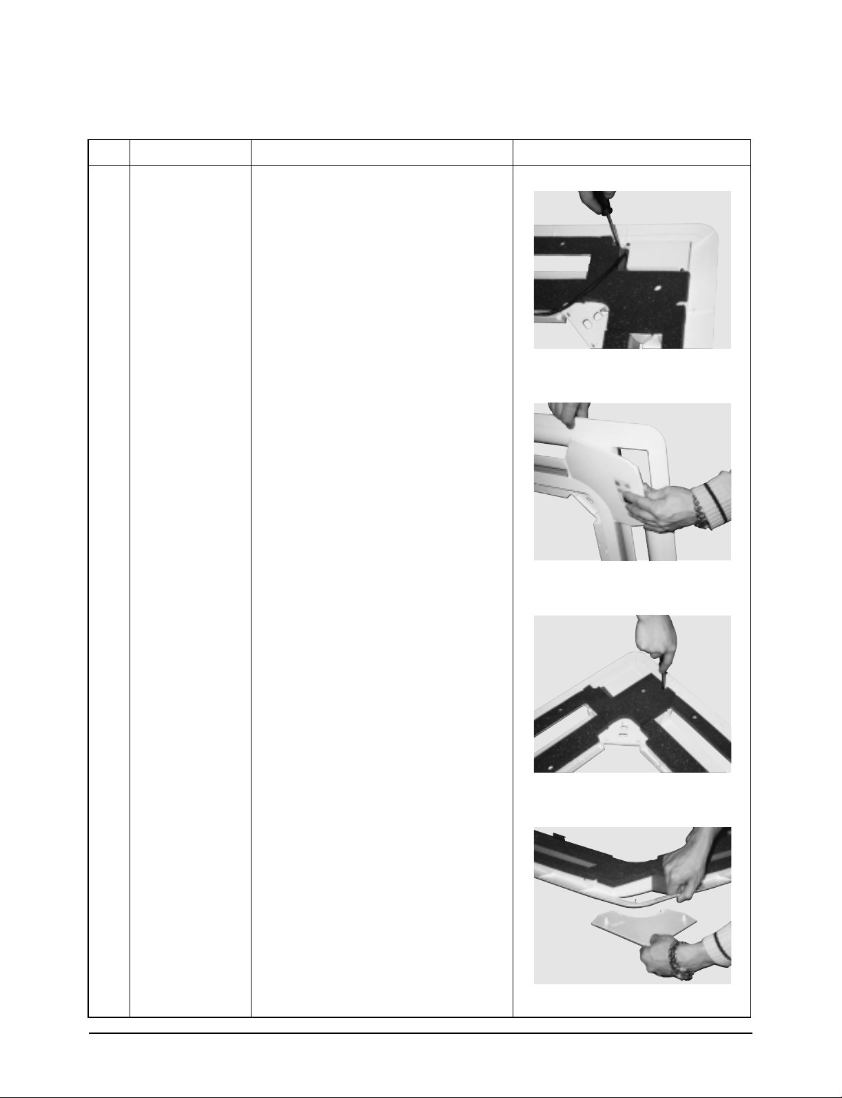
Disassembly and Reassembly
No. Part name Procedures Picture
^
Front panel
-Cover Front
❈ Do !above
Push 3 cover front fixing screws inside the
front panel and snap fixing part to separate
the cover front.
5-14
Samsung Electronics
Page 84
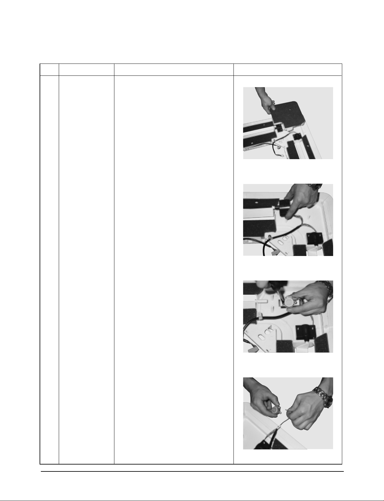
Disassembly and Reassembly
No. Part name Procedures Picture
&
Front panel
- Stepping Motor
❈ Do !above
1. Loosen each one of fixing screw at the
corner part, !cushion side-A and cushion
side-B inside the front panel, and then lift
it up.
2. Remove !the screw of housing motor
L/R fixed at the corner part of front panel
inside and separate
@
Blade-H.
3.!Separate the stepping motor from the
housing motor L/R and
@
separate the motor wire connected.
Samsung Electronics
5-15
Page 85

Disassembly and Reassembly
No. Part name Procedures Picture
*
(
Front panel
- Cushion-A
Front panel
- Bio-pure filter
(Optional)
❈ Do !above
Remove two screws fixing cushion-A inside
the front and lift it up.
❈ Do 1-!, 1-@and 1-#above
1. Separate the bio pure filter from the filter
air.
(remove 4 fixingscrews)
5-16
2. Lift up the bio pure filter case to take the
filter out.
Samsung Electronics
Page 86

Disassembly and Reassembly
Outdoor Unit (18K/24K)
No. Part name Procedures Picture
!
@
Cabinet
Fan Motor &
Propeller Fan
1) Turn off the unit and remove the power
cable
2) Remove the top cover.
3) Remove the control box cover.
4) Unplug the ass'y cable.
5) Remove the cabi-side.
6) Remove the cabi-front.
* When you assemble the parts, check if the
each parts and electric connectors are
fixed firmly.
1) Do Procedure 1 above.
2) Remove the nut flange.
(Turn to the right to remove as it is a left
turned screw)
3) Disassemble the propeller fan.
Samsung Electronics
5-17
Page 87

Disassembly and Reassembly
Outdoor Unit (36K/44K)
No. Part name Procedures Picture
!
Outdoor unit
1) Packaged air conditioner outdoor unit
2) The binders of the front side should be
separated.
3) The flank and the binders should be
separated from each other.
@
5-18
Control box
1) Connect distributed wires in the control
box.
Samsung Electronics
Page 88

6. Trouble Shooting
■ Trouble shooting by outdoor unit error code
ERROR CODE
E1
E5
E6
E9
EA
EC
ED
EL
Indoor unit room thermistor error
Indoor unit pipe thermistor error
Outdoor unit thermistor error
Float switch open error
Communication error between indoor unit and outdoor unit
Communication error between wired remote controller and indoor unit
Outdoor unit pipe thermistor error
Reverse power of 3 phase power source detected (3 phase model)
ERROR DESCRIPTION
■ Trouble shooting by indoor unit receive board
ERROR CODE
Reservation LED flickering(1Hz period)
Operation LED and reservation LED flickering
(1Hz period)
Operation LED and filter LED flickering (1Hz period)
Reservation LED filter LED alternating flickering (1Hz period)
Reservation LED and filter LED flickering (1Hz period)
Operation LED and reservation LED alternating flickering (1Hz period)
Filter LED flickering (1Hz period)
Indoor temperature sensor abnormal
Indoor pipe temperature sensor abnormal
Outdoor temperature sensor abnormal
Float switch open abnormal
Indoor and outdoor communication abnormal
Wired remote controller communication abnormal
Outdoor pipe temperature sensor abnormal
ERROR CODE
REFERENCE PART
EC01
EC02
EC03
EC04
EC05
EC06
EC07
EC08
REFERENCE PART
EC01
EC02
EC03
EC04
EC05
EC06
EC07
■ Trouble shooting by outdoor unit error code
ERROR CODE
*1
*5
*6
*9
*A
*C
*D
*L
✽ The asterisk mark “ * ” + “ERROR” CODE of wired remote controller stands for the set number.
ex) ERROR CODE “39” is the FLOAT SWITCH OPEN ERROR of SET no.3.
Indoor unit room thermistor error
Indoor unit pipe thermistor error
Outdoor unit thermistor error
Float switch open error
Communication error between indoor unit and outdoor unit
Communication error between wired remote controller and indoor unit
Outdoor unit pipe thermistor error
Three phase power incorrect connecting error (In case of three phase power models)
ERROR DESCRIPTION
■ Trouble shooting by outdoor unit error code
ERROR CODE
LED flickering
Samsung Electronics
Communication error between indoor unit and centralized controller
ERROR DESCRIPTION
REFERENCE PART
EC01
EC02
EC03
EC04
EC05
EC06
EC07
EC08
REFERENCE PART
EC20
6-1
Page 89

Trouble Shooting
■ EC01 : Trouble on the thermistor related part of indoor unit.
• EC01 : Trouble on the room thermistor related part of indoor unit.
- E1 of outdoor unit PCB 7-segment
- Reservation lamp of wireless receiving board is flickering with 1 Hz.
- Action items when “*1” display s on the wired rem
Check point :
- Defect of indoor unit
- Indoor unit thermistor defect
Indoor unit thermistor installed at CN8?
YES
Is the vlotage across the thermistor 4.9V and
tabove or 0.5V and lower?
YES
Replace the thermistor
NO
NO
Indoor the indoor unit thermistor at CN8
Replace the indoor unit PCB
✽ “*” stands for the indoor unit address.
■ EC02 : Trouble on the pipe thermistor related part of indoor unit.
- E5 of outdoor unit PCB 7-segment.
- Reservation lamp of wireless receiving board is flickering with 1 Hz.
- Action items when “*5” displays on the wired remote controller.
Check point :
- Indoor unit PCB defect
- Indoor unit pipe thermistor defect
Is the indoor unit pipe thermistor installed at CN8?
YES
Is the voltage across thermistor 4.9V and higher
or 0.5V lower?
YES
Replace the thermistor
6-2
NO
NO
Install the indoor unit pipe thermistor at CN8
Replace the indoor unit
PCB
Samsung Electronics
Page 90

Trouble Shooting
■ EC03 : When the trouble is found on the part related to the outdoor unit thermistor.
- E6 of outdoor unit PCB 7-segment
- Operation lamp and filter lamp of wireless receiving board are flickering with 1Hz.
- Action items when “*6” displays on the wired remote controller.
Check point :
- Defect of indoor unit
- Indoor unit thermistor defect
Is the outdoor unit thermistor installed at CN41?
YES
Is the voltage across the thermistor 4.9V and
higher or 0.5V and lower?
YES
Replace the thermistor
✽ “*” stands for the indoor unit address.
NO
NO
Install the outdoor unit thermistor at CN41.
Replace the outdoor unit PCB
Samsung Electronics
6-3
Page 91

Trouble Shooting
■ EC04 : When the trouble is found on the drain pump and float switch installed on the
indoor unit.
EC01 : Trouble on the thermistor related part of indoor unit.
- E9 of 7-segment of outdoor unit PCB
- Reservation lamp of wireless receiving board and filter lamp are flickering with 1 Hz.
- Action item when “*9” displays on the wireless remote controller.
Check point :
- Indoor unit defect
- Drain pump, float switch defect
Start
Check the
Is available drain
pump?
NO
YES
SW2 ON?
YES YES YES
Is available float
SW?
SW3 ON?
float SW
Replace
indoor unit
PCB
NO
SW2 ON?
YES
SET SW2 OFF
SET SW3 OFF
POWER RESET
Replace PCB
SET SW2 OFF
SET SW3 OFF
✽ “*” stands for the indoor unit address.
Install float SW
6-4
Samsung Electronics
Page 92

Trouble Shooting
■ EC05 : When the trouble is found in the communication related part between indoor unit
and outdoor unit.
- EA of 7-segment of outdoor unit PCB.
- Reservation lamp and filter lamp of wireless receiving board is flickering with 1 Hz.
- Action item when “*A” displays on the wired remote controller.
Check point :
- Indoor unit
- Indoor unit PCB defect
- Outdoor unit PCB defect
↔ outdoor unit mis-connection
Are the terminals N1,L1,C of indoor unit and outdoor unit
are correctly connected? and is the set power on?
YES
Is the LED of PCB flickering with 16Hz for 250ms and
then repeating the on?
NO
Is the LED of PCB flickering with 16Hz?
NO
Replace the PCB
✽ “*” stands for the indoor unit address.
NO
YES
YES
Do connection correctly and check.
Indoor unit communication norma
The Micom of outdoor unit is operating normally,
check and replace the communication circuit of
outdoor unit and indoor unit.
Samsung Electronics
6-5
Page 93

Trouble Shooting
■ EC06 : When the trouble is found in the communication related part between indoor unit
and wired remote controller. (during single operation, not group control)
- EC of 7-segment of outdoor unit PCB.
- Wireless receiving board lamp and reservation lamp is flickering with 1Hz.
- Action item when “C” displays on the wired remote controller.
Check point :
- Short circuit or mis-connection of the communication line between indoor unit and wireless remote controller
- Indoor unit PCB defect
- Wired remote controller PCB defect
Are the terminals R1, R2, R3 of indoor unit terminal
board connected correctly to R1, R2, R3 of wired remote
controller?
YES
Is 7P(RED) of transformer connected to CN11
of indoor unit?
Is the jump wire inserted into CN20 of indoor unit PCB?
YES
Is the address of PCB digital switch of indoor unit to "0"?
YES
Replace the indoor unit PCB
✽ “0” stands for the indoor unit address.
NO
Connect correctly and check.
NO
Connect correctly and check again
NO
Set address to "0"
NO
Replace the wired remote controller
6-6
Samsung Electronics
Page 94

Trouble Shooting
■ EC07 : When the trouble is found in the communication related part between outdoor
unit pipe thermistor.
- ED of 7-segment of outdoor unit PCB.
- Reservation lamp and filter lamp of wireless receiving board is flickering with 1Hz.
- Action item when “D” displays on the wired remote controller.
Check point :
- Indoor unit pipe thermistor available or not
- Indoor unit PCB defect
Is indoor pipe thermistor installed at CN41?
YES
Is the voltage across the thermistor 4.9V and higher
or 0.5V and lower?
YES
Replace the thermistor
✽ “*” stands for the indoor unit address.
NO
Connect correctly and check.
NO
Replace the outdoor PCB
Samsung Electronics
6-7
Page 95
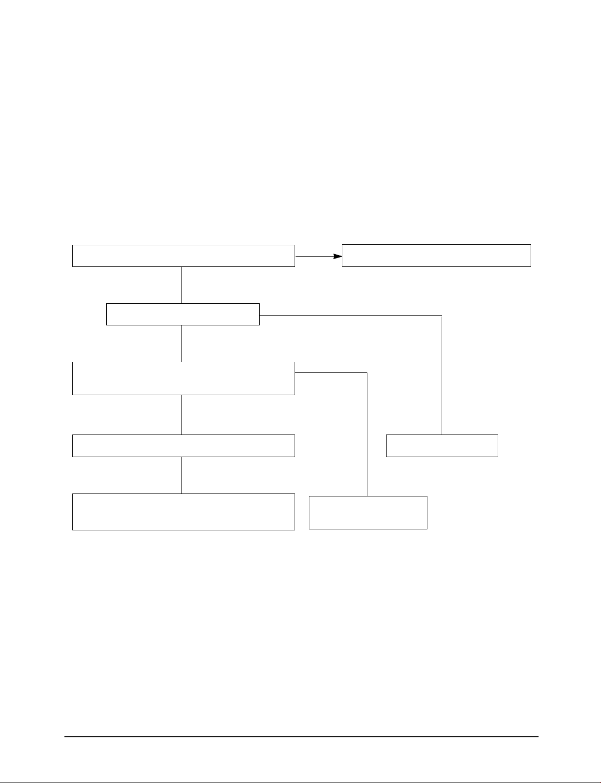
Trouble Shooting
■ EC08 : When the reverse of three phase power is found.
Check point :
- Con check CN76 to connect correctly.
- Check IC51, IC52, IC53 to connect correctly.
Check the Mis-insertion of CN76?
NO
Wire shorted?
NO
Check the pin no 4 of IC51, IC52, IC53,
does this make round type signal?
YES
IC correct
Take two connected lines to change the string of
L1, L2, L3 because of the reverse of power.
YES
Insert correctly
YES
Replace wire
Replace IC that does not
make round type signal
6-8
Samsung Electronics
Page 96

Trouble Shooting
■ EC09 : When the trouble is found on the part related to the wireless receiving board of
the indoor unit.
Check point :
- Defect of wireless remote controller PCB
- Defect of wireless remote controller receiving board PCB
- Indoor unit PCB defect
Mis-insertion of CN9?
NO
Wire shorted?
NO
LED direct/reverse direction check?
NO
Check no.1 and no.2 pin of CN9:DC +5V?
YES
Check pin no.1 of CN9 while pressing
SW91 : DC 0V?
YES
YES
Insert correctly
YES
YES
NO
NO
Replace the wireless receiving board
Replace after check of indoor unit
Samsung Electronics
main PCB
6-9
Page 97

Trouble Shooting
■ EC10 : When the trouble is found on the part related to the wired remote controller.
(single operation)
Check point :
- Defect of communication line between indoor unit and wired remote controller.
- Output of indoor unit Micom
- Defect of wired remote controller PCB
- Indoor unit PCB defect
Is the wired remote
controller energized
when the power is reset?
YES
Is the on/off button command
of wired remote controller
reflected on the set?
YES
When the power is applied
again after removing the
power at the operation on,
does the previous status
display on the wired remote
controller display window?
YES
Does the error code display?
NO NO
Is CN20 of indoor
unit main PCB
NO
NO
remote controlled connected to the R1, R2,
YES
inserted?
YES
Is the address
of indoor unit "0"
More than on indoor
unit mounted on the
wired remote
controller?
NO
Are the terminals R1, R2, R3 of wired
R3 of indoor unit terminal boards?
NO
NO
YES
CN20
insertion
Set to "0"
One unit is
installed
Is the wire of CN15 to
indoor unit terminal
board shorted?
NO
YES
Check the indoor
unit PCB
YES
Replace the
wiring
NO
Check the main PCB of
indoor unit and replace it.
6-10
Connect correctly the R1, R2, R3
Error correction and recheck
Samsung Electronics
Page 98
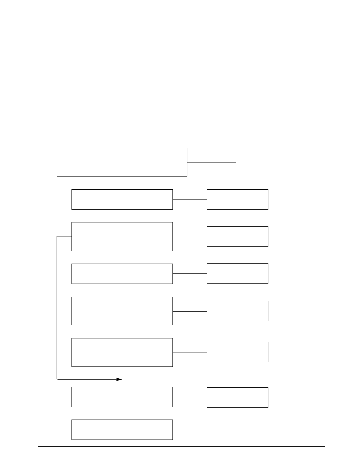
Trouble Shooting
■ EC11 : When the trouble is found on the part related to the fan motor of indoor unit.
Check point :
- Defect of PCB relay of indoor unit.
- Output of indoor unit Micom
- Indoor fan motor defect
- Defect of PCB IC06 of indoor unit
Is the power source normal? AC220 ~ 240 50Hz
Is the wire harness for motor connection good?
Is the terminal contact of fan motor condenser good?
YES
During the wind control, does it change
to breeze, weak, strong and auto wind?
NO
YES
When changing the wind to
breeze, weak, strong and auto,
do RY73, RY74, RY75 operate?
NO
Is he output pin of micom high when
selecting each wind control mode?
YES
When selecting the each wind control
mode, is the voltage across the replay of
indoor unit PCB 12V?
NO
NO
NO
NO
NO
Normal
Check micom and
replace
Check micom and
replace
Check micom and
replace
Check the replay part
and replace
micom, are the pin 14 and 15 of indoor
Is the voltage across the indoor unit fan
Samsung Electronics
YES
When selecting each wind control of
unit PCB IC06 low?
YES
AC220 ~ 240V?
YES
Check the indoor unit fan motor
and replace
NO
NO
Check IC06 and
replace
Replace PCB
6-11
Page 99
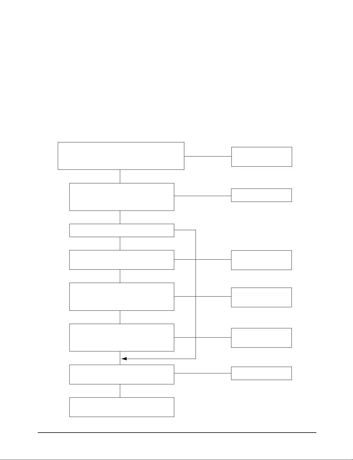
Trouble Shooting
■ EC12 : When the trouble is found on the part related to the fan motor of outdoor unit.
Check point :
- Outdoor unit PCB relay defect
- Output of outdoor unit micom
- Outdoor unit fan motor defect
- Defect of IC07 of outdoor unit PCB
Is the power source normal? AC220~240 50Hz
Is the wire harness for motor connection good?
Is the terminal contact of fan motor condenser good?
YES
Does the outdoor fan motor changes to mild
and strong wind during the cooling
operation?
NO
Do the RY73, RY74 operate?
NO
Is the wind volume output pin of micom high
when each wind control is operation?
YES
Is the voltage across the PCB relay 12V
when the each wind control of micom
is opeating?
YES
YES
NO
NO
YES
NO
Check and replace
the related part
Normal
Check and replace
the micom
Check and replace
the relay
6-12
Are the pins 11 and 12 of IC07 of outdoor
unit PCB low when each wind control mode
micom is operation?
YES
Is the voltage across the outdoor unit
fan motor AC220~240V?
YES
Check outdoor unit fan motor and replace
NO
NO
Check and replace
IC07
Replace PCB
Samsung Electronics
Page 100

■ EC13 : When the trouble is found on the part related to comp of outdoor unit.
Check point :
- Indoor unit PCB relay defect
- Output of indoor unit micom
- Comp defect
- Magnet switch defect
Trouble Shooting
Is the power source normal? AC220~240 50Hz
Is there no wrong connection and contact of indoor
and outdoor connection wire?
Is the compressor being delayed for 3 minutes?
Is the desired temperature set higher than the current
one during the cooling operation?
Is the desired temperature set lower than the current
one during the cooling operation?
YES
Is the RY71 on and compressor operating
when cooling mode operates and indoor unit
PCB is shorted?
YES
Is the output of outdoor unit micom pin 57
high when the compressor is on?
Is the voltage across RY7 coil of
outdoor PCB 12V?
NO
Check and replace
the related part
Normal
Check and replace
micom (IC04)
Samsung Electronics
Is the output of NO. 10 of IC05 of outdoor
unit low then the compressor is on?
Is the voltage AC220V across the terminal
of outdoor unit when the compressor is on?
Replace the compressor
Check and replace
IC05
Replace the magnet
replay
6-13
 Loading...