

Samsung CH052EAM, CH094EAM, CH105EAM, CH128EAM, CH070EAM Installation Manual
...
ENGLISH
INSTALLATION MANUAL
MANUAL DE INSTALACIÓN
MANUEL D’INST ALLA TION
MANUALE D’INST ALLZIONE
MANUAL DE INSTALAÇÃO
INST ALLATIONS-HANDBUCH
E°XEIPI¢IO E°KATA™TA™H™
азлнкмдсаь ий млнДзйЗдЦ
System Air Conditioner (Cool and Heat)
Aire acondicionado sistemático
(Refrigeración y Calefacción)
Climatiseur numérique multifonctionnel
(Refroidissement et Chauffage)
Sistema Aria Condizionata
(Raffreddamento e Riscaldamento)
Sistema Ar Condicionado
(Refrigeração e Aquecimento)
Klimaanlage System
(Kühlen und Wärmen)
™‡ЫЩЛМ· ∫ПИМ·ЩИЫМФ‡ (æ‡Í˘ Î·È £¤ÚÌ·ÓÛ˘)
лЛТЪВПМ˚И ЗУБ‰Ы¯М˚И дУМ‰ЛˆЛУМВ
(éı·ʉÂÌËÂ Ë Ó·Ó„Â‚)
ESPAÑOL
FRANÇAIS
ITALIANO
PORTUGUÊS
DEUTSCH
E§§HNIKA
RUSSIAN
E S F I P D G R DB98-11886A(3)
CH052EAM
CH070EAM
CH094EAM
CH105EAM
CH128EAM
CH140EAM

■ Parts List . . . . . . . . . . . . . . . . . . . . . . . . . . . . . . . . . . . . . . . . . . . 24
OO
OO
PPPPTTTTIIIIOOOONNNNAAAALL
LL
AA
AA
CCCCCCCCEEEESSSSSSSSOOOORRRRIIIIEEEESS
SS
Chapter
Contents
E-2
■ Preparation for Installation . . . . . . . . . . . . . . . . . . . . . . . . . . . . . . . 4
■ Deciding on Where to Install the Indoor Unit . . . . . . . . . . . . . . . . . 5
■ Indoor Unit Installation . . . . . . . . . . . . . . . . . . . . . . . . . . . . . . . . . . 8
■ Purging the Unit . . . . . . . . . . . . . . . . . . . . . . . . . . . . . . . . . . . . . . . 9
■ Connecting the Refrigerant Pipe . . . . . . . . . . . . . . . . . . . . . . . . . 10
■ Cutting/Flaring the Pipes . . . . . . . . . . . . . . . . . . . . . . . . . . . . . . . 11
■ Performing Leak Test & Insulation . . . . . . . . . . . . . . . . . . . . . . . . 12
■ Drainpipe and Drain Hose Installation . . . . . . . . . . . . . . . . . . . . . 13
■ Connecting the Connection Cord . . . . . . . . . . . . . . . . . . . . . . . . . 15
■ Assigning Address to Indoor Unit . . . . . . . . . . . . . . . . . . . . . . . . . 16
■ Installing the Safety Net . . . . . . . . . . . . . . . . . . . . . . . . . . . . . . . . . 18
■ Bio-pure Filter Installation(Optional) . . . . . . . . . . . . . . . . . . . . . . . 18
■ Troubleshooting . . . . . . . . . . . . . . . . . . . . . . . . . . . . . . . . . . . . . . 19
4444 WW
WW
AAAAYY
YY
CC
CC
AAAASSSSSSSSEEEETTTTTTTTEE
EE
II
II
NNNNSSSSTTTTAAAALLLLLLLLAAAATTTTIIIIOOOONN
NN
Chapter
■ Preparation for Installation . . . . . . . . . . . . . . . . . 4
■ Deciding on Where to Install the Indoor Unit . . . 5
■ Indoor Unit Installation . . . . . . . . . . . . . . . . . . . . 8
■ Purging the Unit . . . . . . . . . . . . . . . . . . . . . . . . 9
■ Connecting the Refrigerant Pipe . . . . . . . . . . . 10
■ Cutting/Flaring the Pipes . . . . . . . . . . . . . . . . . 11
■ Performing Leak Test & Insulation . . . . . . . . . . 12
■ Drainpipe and Drain Hose Installation . . . . . . . 13
■ Connecting the Connection Cord . . . . . . . . . . 15
■ Assigning Address to Indoor Unit . . . . . . . . . . 16
■ Installing the Safety Net . . . . . . . . . . . . . . . . . 18
■ Bio-pure Filter Installation(Optional) . . . . . . . . 18
■ Troubleshooting . . . . . . . . . . . . . . . . . . . . . . . . 19
4444 WW
WW
AAAAYY
YY
CC
CC
AAAASSSSSSSSEEEETTTTTTTTEE
EE
II
II
NNNNSSSSTTTTAAAALLLLLLLLAAAATTTTIIIIOOOONN
NN
Chapter
E-3
ENGLISH

Preparation for Installation
When deciding on the location of the air conditioner with the owner,
the following restrictions must be taken into account.
General
Do NOT install the air conditioner in a location where it will come into
contact with the following elements:
◆
Combustible gases
◆
Saline air
◆
Machine oil
◆
Sulphide gas
◆
Special environmental conditions
If you must install the unit in such conditions, first consult your dealer.
Accessories
◆ The following accessories are supplied with the indoor unit.
The type and quantity may differ depending on the specifications.
E-4
Pattern sheet InsulationInsulation cover
drain
Insulation cover
band
Insulation pipe
Insulation drain
hose
Installation manual
Cable-tie
Flexible hose
M4x12 tapped
Screw
Instruction manual Pad stopper
Safety net M4x12 tapped
Screw

Deciding on Where to Install the Indoor Unit
Indoor Unit
◆
There must be no obstacles near the air inlet and outlet.
◆
Install the indoor unit on a ceiling that can support its weight.
◆
Maintain sufficient clearance around the indoor unit.
◆
Make sure that the water dripping from the drain hose runs away correctly
and safely.
◆
The indoor unit must be installed in this way, that they are out of public
access. (Not touchable by the users)
E-5
ENGLISH
Space Requirements for Indoor Unit

Deciding on Where to Install the Indoor Unit (continued)
E-6
OPEN
CLOSED
OPEN
CLOSED
404
403
196
Suspension bolt
4-M8~M10
41
255
840
10-M4 Hole
(prepared hole)
Fresh air intake hole
55
246
230
100
80
55
290
2x230=26025
20
25
198
293
256
318
111
141
Drawing of the indoor unit
✴✴
052/070/094/105
✴✴
Unit : mm
Liquid pipe connection
Gas pipe connection
ø
6.35 (1/4") : ✴✴052/070
✴✴
ø
9.52 (3/8") : ✴✴094/105
✴✴
ø
12.70 (1/2") : ✴✴052
✴✴
ø
15.88 (5/8") : ✴✴070/094
✴✴
ø
19.05 (3/4") : ✴✴105
✴✴
No.
Name
Remark
1
2
Drain pipe connection
Power supply connection
Air discharge grille
Air suction grille
3
4
5
6

E-7
ENGLISH
404
403
Suspention bolt
4-M8~M10
5555
adjustable 0~550
750
28848
196
293 255
41
111
141
256
318
840
55
840 55
2525
20
198
158
138
304
288
68
290
2x230=260
10-M4 Hole
(prepared hole)
Branch duct
connection
OPEN
CLOSED
OPEN
CLOSED
1
2
3
4
5
6
Liquid pipe connection
Gas pipe connection
Drain pipe connection
Power supply connection
Air discharge grille
Air suction grille
ø
9.52(3/8")
ø
19.05(3/4")
No.
Name
Remark
✴✴
128/140
✴✴
Unit : mm
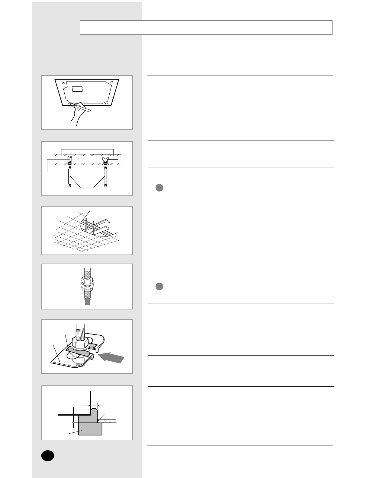
Indoor Unit Installation
It is recommended to install the refnet joint before installing the indoor unit.
E-8
Concrete
Suspension bolt(M8)-field supply
Hole in anchor
Hole in plug
Insert
Ceiling support
20mm
Indoor Unit
Ceiling
Gauge of
Dimensions
17mm
1
Place the pattern sheet on the ceiling at the spot where you want to
install the indoor unit.
2
Insert bolt anchors, use existing ceiling supports or construct a suitable
support as shown in figure.
3
Install the suspension bolts depending on the ceiling type.
4
Screw eight nuts to the suspension bolts making space for hanging
the indoor unit.
5
Hang the indoor unit to the suspension bolts between two nuts.
6
Screw the nuts to suspend the unit. Cut a pad stopper and place it on the
bracket at this time.
7
Adjust the unit to the appropriate position considering the installation area for the front
panel.
7-1 Place the pattern sheet on the indoor unit.
7-2 Adjust a space between the ceiling and the indoor unit by using the gauge
of dimensions.
7-3 Fix the indoor unit securely after adjusting level of the unit by using a leveler.
7-4 Remove the pattern sheet, connect the other cables and install the front panel.
◆ Ensure that the ceiling is strong enough to support
the weight of the indoor unit.
Before hanging the unit, test the strength of each
attached suspension bolt.
◆ If the length of suspension bolt is more than 1.5m,
it is required to prevent vibration.
IMPORTANT
You must install the suspension bolts more than four
when installing the indoor unit.
IMPORTANT
◆ Piping must be laid and connected inside the ceiling when
suspending the unit. If the ceiling is already constructed,
lay the piping into position for connection to the unit before
placing the unit inside the ceiling.
NNNNoooottttee
ee
◆ Since the diagram is made of paper, it may shrink or stretch
slightly due to temperature or humidity. For this reason, before
drilling the holes maintain the correct dimensions between the
markings; refer to page 6 or 7.
NNNNoooottttee
ee
Pad stopper
Bracket
 Loading...