

Samsung CH44CA, CH44CAX, CH140EAMC, UH140GAMC, CH105EAMC Service Manual
...
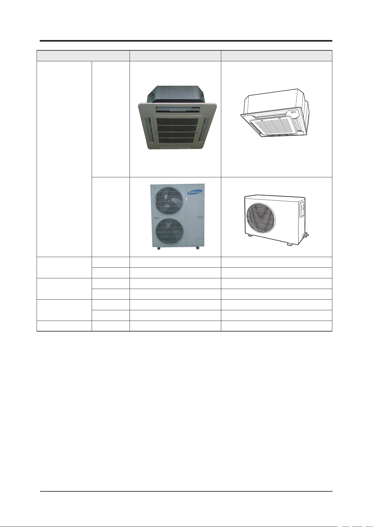
SYSTEM AIR CONDITIONER
Basic : CH44CA CH44CAX
Model
Model
Code
SERVICE
INDOOR
:
CH140EAMC UH140GAMC
CH105EAMC UH105GAMC
CH070EAMC UH070EAMC
CH052EAMC
CH094EAMC
:
CH140EAMC UH140GAMC
CH105EAMC UH105GAMC
CH070EAMC UH070EAMC
CH052EAMC UH052EAMC
CH094EAMC UH094EAM1C
UNIT OUTDOOR UNIT
UH052EAMC
UH094EAM1C
Manual
AIR CONDITIONER THE FEATURE OF PRODUCT
Energy Saving Function
Long Lasting Outdoor Unit
High Ceiling Operation
: Up to 3.6m height
Built-in Drain Pump
: Max. 750mm
Long Piping
Refer to the service manual in the GSPN(see the rear cover) for the more information.

Contents
11. Precautions
1-1 Installing the air conditioner
1-2 Power supply and circuit breaker
1-3 During operation
1-4 Disposing of the unit
1-5 Others
12. Product Specifications
2-1 The Feature of Product
2-2 The abbreviated technology words & the definition of technology terms
2-3 Product Specifications
2-4 The Comparative Specifications of Product
2-5 Accessory and Option Specifications
3. Alignment and Adjustments
3-1 Indoor Display Error and Check Method
3-2 Setting Option Setup Method
..... ... .. ... ... .. ... ... .. ... ... .. ... ... .. ... ... .. ... ... .. ... ... .. ... ... .. ... ... .. ... ... .. ... ... .. ... ... .. .
.... ... ..... ... ..... ... ..... ... ..... ... ..... ... ..... ... ..... ... ..... ... ..... ... ..
.... ... ... .. ... ... .. ... ... .. ... ... .. ... ... .. ... ... .. ... ... .. ... ... .. ... ..
. ..... ... ..... ... ..... ... ..... ... ..... ... ..... ... ..... ... ..... ... ..... ... ..... ... ..... ... ..... ... .
.... ... ..... ... ..... ... ..... ... ..... ... ..... ... ..... ... ..... ... ..... ... ..... ... ..... ... .....
...... ... ..... ... ..... ... ..... ... ..... ... ..... ... ..... ... ..... ... ..... ... ..... ... ..... ... ..... ... ..... ... ..... ...
... ... ..... ... ..... ... ..... ... ..... ... ..... ... ..... ... ..... ... ..... ... ..... ... ..... ... .
... .. ... ... .. ... ... .. ... ... .. ... ... .. ... ... .. ... ... .. ... ... .. ... ... .. ... ... .. ... ... .. ..
.... ..... ... ..... ... ..... ... ..... ... ..... ... ..... ... ..... ... ..... ... ..... ... ..... ... ....
.. .. ... ... .. ... ... .. ... ... .. ... ... .. ... ... .. ... ... .. ... ..
... ... ..... ... ..... ... ..... ... ..... ... ..... ... ..... ... ..... ... ..... .
.. ... .. ... ... .. ... ... .. ... ... .. ... ... .. ... ... .. ... ... .. ... ... .. ... ... .. ... ...
.... ... .. ... ... .. ... ... .. ... ... .. ... ... .. ... ... .. ... ... .. ... ..
... .. ... ... .. ... ... .. ... ... .. ... ... .. ... ... .. ... ... .. ... ... .. ... ... .. ... ... .. ..
.... ... .. .
1-1
1-1
1-1
1-2
1-2
1-2
2-1
2-1
2-1
2-2
2-3
2-4
3-1
3-1
3-4
14. Disassembly and Reassembly
4-1 Indoor Unit
4-2 Outdoor Unit
.. .. ... ... .. ... ... .. ... ... .. ... ... .. ... ... .. ... ... .. ... ... .. ... ... .. ... ... .. ... ... .. ... ... .. ... ... .. ... ...
... .. ... ... .. ... ... .. ... ... .. ... ... .. ... ... .. ... ... .. ... ... .. ... ... .. ... ... .. ... ... .. ... ... .. ... ... .. ..
15. Exploded Views and Parts List
5-1 Indoor Unit
5-2 Panel
5-3 Outdoor Unit
5-4 Ass’y Control In
5-
5 Ass’y Control Out
6. Electrical Parts List
7. Wiring Diagram
7-1 Indoor Unit
7-2 Outdoor Unit
8. Schematic Diagram
.. .. ... ... .. ... ... .. ... ... .. ... ... .. ... ... .. ... ... .. ... ... .. ... ... .. ... ... .. ... ... .. ... ... .. ... ... .. ... ...
... ... .. ... ... .. ... ... .. ... ... .. ... ... .. ... ... .. ... ... .. ... ... .. ... ... .. ... ... .. ... ... .. ... ... .. ... ... .. ... ... .. ..
... ... .. ... ... .. ... ... .. ... ... .. ... ... .. ... ... .. ... ... .. ... ... .. ... ... .. ... ... .. ... ... .. ... ... .. ... ... ..
... ... ... .. ... ... .. ... ... .. ... ... .. ... ... .. ... ... .. ... ... .. ... ... .. ... ... .. ... ... .. ... ... .. ... ... ..
... ... ... .. ... ... .. ... ... .. ... ... .. ... ... .. ... ... .. ... ... .. ... ... .. ... ... .. ... ... .. ... ... .. ... ...
....... ... ..... ... ..... ... ..... ... ..... ... ..... ... ..... ... ..... ... ..... ... ..... ... ..... ... ...
.. ... .. ... ... .. ... ... .. ... ... .. ... ... .. ... ... .. ... ... .. ... ... .. ... ... .. ... ... .. ... ... .. ... ... .. ... ..
.. .. ... ... .. ... ... .. ... ... .. ... ... .. ... ... .. ... ... .. ... ... .. ... ... .. ... ... .. ... ... .. ... ... .. ... ... .. ... ...
... .. ... ... .. ... ... .. ... ... .. ... ... .. ... ... .. ... ... .. ... ... .. ... ... .. ... ... .. ... ... .. ... ... .. ... ... .. ..
.... ... ... .. ... ... .. ... ... .. ... ... .. ... ... .. ... ... .. ... ... .. ... ... .. ... ... .. ... ... .. ... ... ..
..... ... .. ... ... .. ... ... .. ... ... .. ... ... .. ... ... .. ... ... .. ... ... .. ... ...
.. ... ... .. ... ... .. ... ... .. ... ... .. ... ... .. ... ... .. ... ... .. ... ... .. ... ...
4-1
4-1
4-10
5-1
5-1
5-4
5-6
5-14
5-20
6-1
7-1
7-1
7-4
8-1
8-1 Indoor Unit
.. .. ... ... .. ... ... .. ... ... .. ... ... .. ... ... .. ... ... .. ... ... .. ... ... .. ... ... .. ... ... .. ... ... .. ... ... .. ... ...
8-2 Outdoor Unit
... .. ... ... .. ... ... .. ... ... .. ... ... .. ... ... .. ... ... .. ... ... .. ... ... .. ... ... .. ... ... .. ... ... .. ... ... .. ..
8-1
8-2

Contents
9. Circuit Descriptions
9-1 PCB Circuit Descriptions
9-2 Refrigerating Cycle Diagram
10. PCB Diagram
10-1 Indoor PCB
10-2 Outdoor PCB
11. Operating Instructions
11-1 Name of Each Part
11-2 Main Function
... .. ... ... .. ... ... .. ... ... .. ... ... .. ... ... .. ... ... .. ... ... .. ... ... .. ... ... .. ... ... .. ... ... .. ..
.... .. ... ... .. ... ... .. ... ... .. ... ... .. ... ... .. ... ... .. ... ... .. ... ... .. ... ... .. ... ... .
. ... .. ... ... .. ... ... .. ... ... .. ... ... .. ... ... .. ... ... .. ... ... .. ... ... .. ... ... .. ..
.. .. ... ... .. ... ... .. ... ... .. ... ... .. ... ... .. ... ... .. ... ... .. ... ... .. ... ... .. ... ... .. ... ... .. ... ... .. ...
.. ... .. ... ... .. ... ... .. ... ... .. ... ... .. ... ... .. ... ... .. ... ... .. ... ... .. ... ... .. ... ... .. ... ... .. ... ... ..
. ... .. ... ... .. ... ... .. ... ... .. ... ... .. ... ... .. ... ... .. ... ... .. ... ... .. ... ... .. ... ... .. ... ... .. ... ... .
... .. ... ... .. ... ... .. ... ... .. ... ... .. ... ... .. ... ... .. ... ... .. ... ... .. ... ... .. ... ... .. ... .
..... ... .. ... ... .. ... ... .. ... ... .. ... ... .. ... ... .. ... ... .. ... ... .. ... ... .. ... ... .. ... ... .. ..
... .. ... ... .. ... ... .. ... ... .. ... ... .. ... ... .. ... ... .. ... ... .. ... ... .. ... ... .. ... ... .. ... ... .. ... ... .
11-3 Wireless Remote Control-Buttons and Display
11-4 Wired Remote Controller-Buttons and Display
12. Troubleshooting
12-1 Operation Specification
12-2 Troubleshooting
12-3 Sequence for trouble diagnosis
.... ... ..... ... ..... ... ..... ... ..... ... ..... ... ..... ... ..... ... ..... ... ..... ... ..... ... ..... ... ....
.. ... ... .. ... ... .. ... ... .. ... ... .. ... ... .. ... ... .. ... ... .. ... ... .. ... ... .. ... ... .. ... .
... .. ... ... .. ... ... .. ... ... .. ... ... .. ... ... .. ... ... .. ... ... .. ... ... .. ... ... .. ... ... .. ... ... .. ... .
.. .. ... ... .. ... ... .. ... ... .. ... ... .. ... ... .. ... ... .. ... ... .. ... ... .. ... .
13. Block Diagram
.... ... ..... ... ..... ... ..... ... ..... ... ..... ... ..... ... ..... ... ..... ... ..... ... ..... ... ..... ... ..... ..
... .. ... ... .. ... ... .. ... ... .. ... ... .. ... ... .. ... ...
...... ... ..... ... ..... ... ..... ... ..... ... ..... ... ..
9-1
9-1
9-3
10-1
10-1
10-3
11-1
11-1
11-3
11-9
11-10
12-1
12-1
12-3
12-6
13
13-1 Indoor Unit
13-2 Outdoor Unit
14. Reference Sheet
14-1 Index for Model Name
14-2 Pressure Graph
14-3 Pressure & Capacity mark
14-4 Q & A for Non-trouble
14-5 Cleaning/Filter Change
14-6 Installation
.. ... ... .. ... ... .. ... ... .. ... ... .. ... ... .. ... ... .. ... ... .. ... ... .. ... ... .. ... ... .. ... ... .. ... ... .. ... ...
. ... .. ... ... .. ... ... .. ... ... .. ... ... .. ... ... .. ... ... .. ... ... .. ... ... .. ... ... .. ... ... .. ... ... .. ... ... ..
... ... .. ... ... .. ... ... .. ... ... .. ... ... .. ... ... .. ... ... .. ... ... .. ... ... .. ... ... .. ... ... .. ... ... .. .
.... ... ..... ... ..... ... ..... ... ..... ... ..... ... ..... ... ..... ... ..... ... ..... ... ..... ...
..... ... ..... ... ..... ... ..... ... ..... ... ..... ... ..... ... ..... ... ..... ... ..... ... ..... ... ..... ... .
... ..... ... ..... ... ..... ... ..... ... ..... ... ..... ... ..... ... ..... ... ..... ... ..... .
.. .. ... ... .. ... ... .. ... ... .. ... ... .. ... ... .. ... ... .. ... ... .. ... ... .. ... ... .. ... ... .. ... .
... ... ..... ... ..... ... ..... ... ..... ... ..... ... ..... ... ..... ... ..... ... ..... ... ..... ...
. .. ... ... .. ... ... .. ... ... .. ... ... .. ... ... .. ... ... .. ... ... .. ... ... .. ... ... .. ... ... .. ... ... .. ... ... .. ... ...
14-7 Installation Diagram of Indoor Unit and Outdoor Unit
..... ... .. ... ... .. ... ... .. ... ... .. ... ... .
13
13
14-1
14-1
14-2
14-2
14-3
14-6
14-7
14-8
Samsung Electronics
1. Precautions
s
u
o
r
e
g
n
a
d
1-1 Installing the air conditioner
Users should not install the air conditioner by themselves.
Ask the dealer or authorized company to install the air conditioner except
the window-type air conditioner in U.S.A and Canada.
If you don’t install the air conditioner properly, it may cause a fire, a water
leakage or an electric shock.
You must install the air conditioner according to the national wiring regula-
tions and safety regulations.
Install the indoor unit higher than 2.5m from the floor to avoid the injury
caused by the operation of the fan. (except the window-type air condition
er)
The manufacturer is not responsible for any accidents or injury caused by
an incorrect installation.
When installing the built-in type air conditioner, keep all electric cables
such as the power cable and the connection cord in pipes, ducts, or cable
channels to protect them from the danger of impact or any other incidents.
-
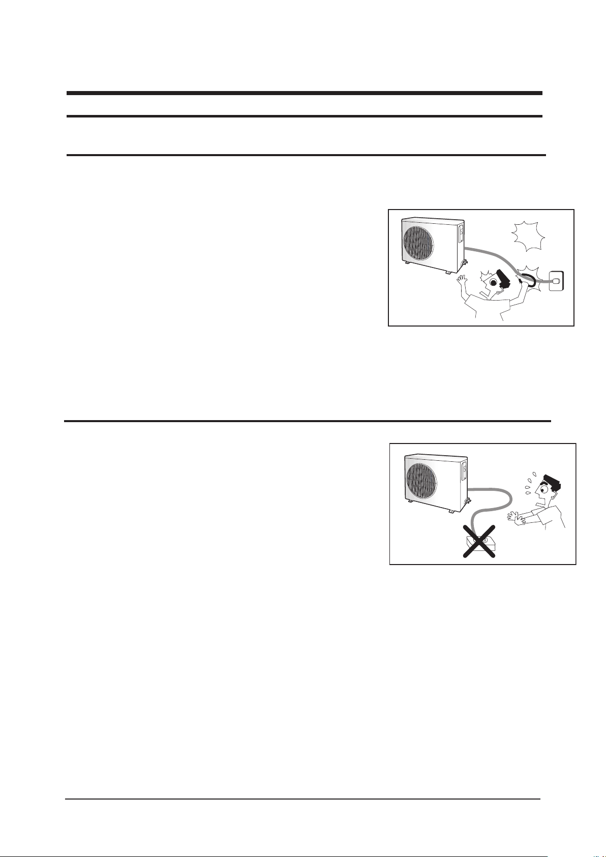
Avoid Dangerous Contact
1-2 Power supply and circuit breaker
If the power cord of the air conditioner is damaged, it must be replaced by the
manufacturer or a qualified person in order to avoid a hazard.
The air conditioner must be plugged into an independent circuit if applicable or
connect the power cable to the auxiliary
An all pole disconnection from the power supply must be incorporated in the
fixed wiring with a contact opening of >3mm.
Do not extend an electric cord to the air conditioner.
The air conditioner must be plugged in after you complete the installation.
circuit breaker.
No Tapping and No Extension Cords
1-1
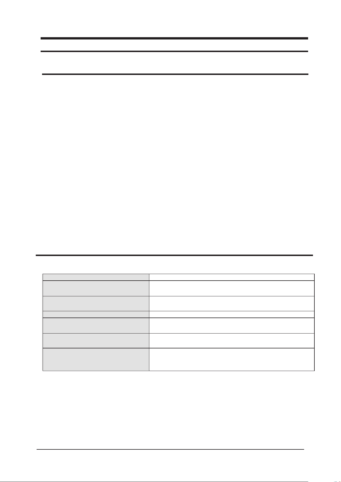
1-3 During operation
Do not repair the air conditioner at your discretion.
It is recommended to contact a service center directly.
Never spill any kind of liquid on the air conditioner.
If this happens, turn off the air conditioner and contact an authorized service
center.
Do not insert anything between the airflow blades to prevent damage of the
inner fan and consequent injury. Keep children away from the air conditioner.
Do not place any obstacles in front of the air conditioner.
Do not spray any kind of liquid into the indoor unit. If this happens, turn off the
air conditioner and contact a service center.
Make sure that the air conditioner is well ventilated at all times:
Do not place a cloth or other materials over it.
Remove the batteries if you don’t use the remote control for a long time. (If
applicable)
Use the remote control within 7 meters from the indoor unit. (If applicable)
No children Nearby
1-4 Disposing of the unit
Before throwing out the air conditioner, remove the batteries from the remote control.
When you dispose of the air conditioner, consult your dealer. If pipes are removed incorrectly, refrigerant may blow out and
cause air pollution. When it contacts with your skin, it can cause skin injury.
The package of the air conditioner should be recycled or disposed of properly for environmental reasons.
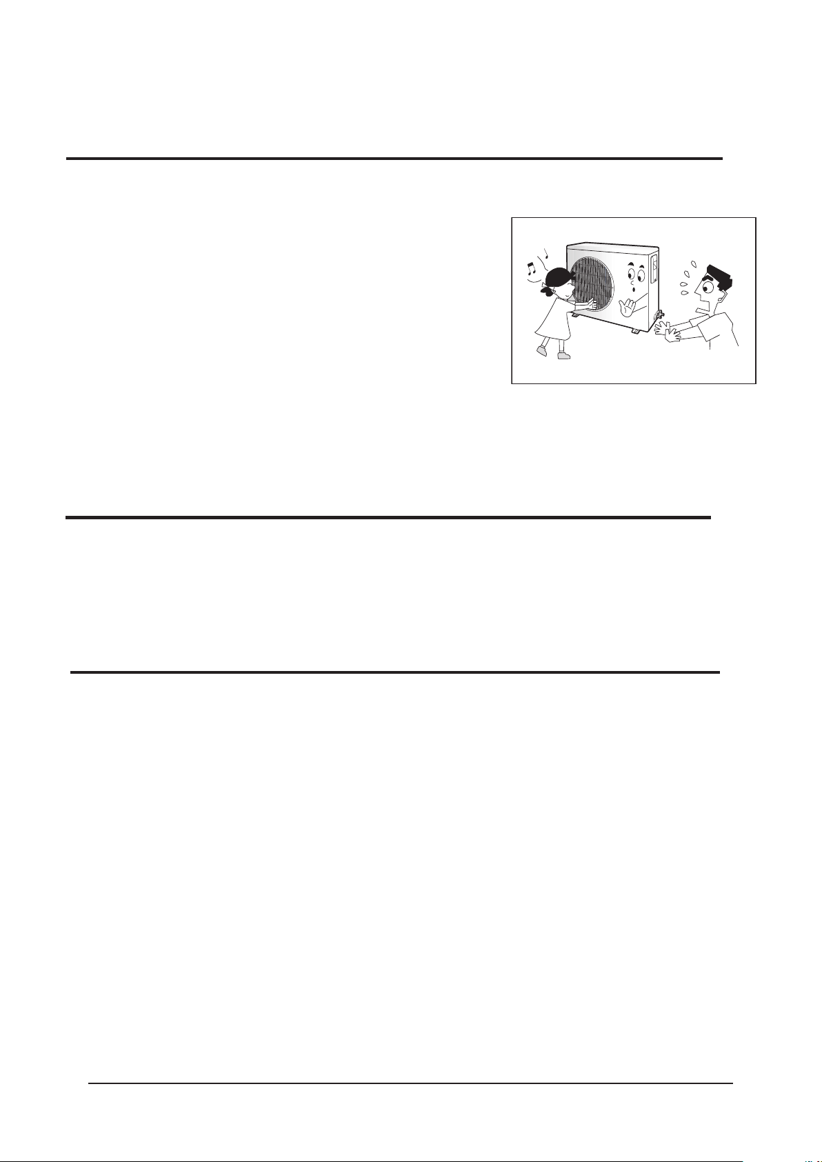
1-5 Others
Never store or load the air conditioner upside down or sideways to prevent the damage to the compressor.
Young children or infirm persons should be always supervised when they use the air conditioner.
Max current is measured according to IEC standard for safety.
Current is measured according to ISO standard for energy efficiency.
Samsung Electronics
1-2
Samsung Electronics
2. Product Specifications
2-1 The Feature of Product
Energy saving function
Make a profit room temperature with energy saving function(high efficiency air conditioner).
Long Lasting Indoor & Outdoor Units
Anti-Corrosion Outdoor Cabinet & anti-Bacteria Indoor Heat Exchanger.
High Ceiling Operation
Broader and wider blow supports up to 3.6 meters high.
Built-in Drain Pump
Drain Pump for 750mm height difference.
Auto Changeover
Cooling or Heating automatic operation due to room temperature.
Long Piping
Max. 50m length & 30m height.
2-2 The abbreviated technology words & the definition of technology terms
Abbreviated technology words Definition of technology terms
COMP
( Full name:compressor )
BLOWER One that blows, especially a mechanical device, such as a fan, that pro-
FAN A device for creating a current of air or a breeze.
ASSY CONTROL BOX
(Full name : assemble control box)
MOTOR Something, such as a machine or an engine, that produces or imparts-
ASSY EVAP / ASSY COND( Full name :
assemble evaporator / assemble con
denser )
One that compresses, especially a machine used to compress gases.
duces a current of air.
A restraining device of air-condition, measure, or limit.
motion.
Heat exchanger; A device, used to transfer heat from a fluid on oneside of
-
a barrier to a fluid on the other side without bringing the fluidsinto direct
contact.
2-1
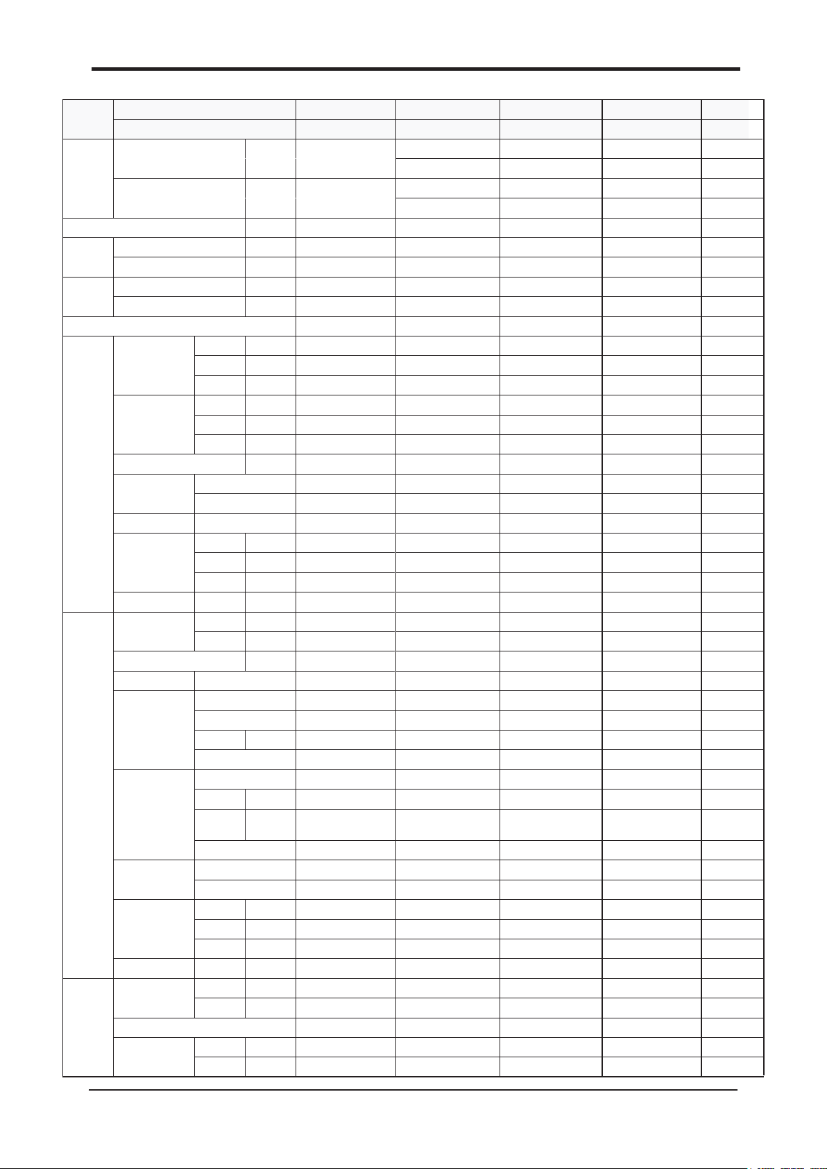
2-3 Product Specifications
MODEL
Capacity
Power
Input
Running
Current
Indoor
Unit
Outdoor
Unit
Piping
INDOOR UNIT CH140EAMC CH105EAMC CH070EAMC
OUTDOOR UNIT UH140GAMC UH105GAMC UH070EAMC
Cooling
Heating
Power Supply
Cooling W 5,300 3,560 2,400
Heating W 5,900 3,600 2,350
Cooling A 9.20 6.20 11.0
Heating A 10.00 6.30 11.0
Max current / power 11.5 A/6.5kW 8.10A/4.39 kW 13.5A/3.05kW
Hi r.p.m 600 ±20 540/520 ±20 460/440 ±20
Fan Speed
Air Flow Rate
Noise Level( Cooling/ Heating ) dB(A) 49/50 47/48 43/44
Heat Exchanger
Fan Type Turbo Turbo Turbo
Dimensions
Weight Net/Gross kg 29/35 28/34 25/ 31
Fan Speed
Noise Level( Cooling/ Heating ) dB(A) 67/68 65/66 60/61
Fan Type Propeller Propeller Propeller
Compressor
Refrigerant
Heat Exchanger
Dimensions
Weight Net/Gross kg 121/1 36 87/92 60/67
Pipe O.D Size
Connection Method Flare Flare Flare
Between
Mid r.p.m 560±20 500/480 ±20 44 0/420 ±20
Low r.p.m 520 ±20 460/440 ±20 420/400 ±20
Hi m3/min 29 24.5 18.5
Mid m3/min 27 22.5 17.0
Low m3/min 25 20.5 16.0
Row sxStagesxFin pitch 2*13*1.4 2*12*1.5 2*8*1.6
H mm 298 298 218
W mm 840 840 840
D mm 840 840 840
Hi r.p.m 1020 ±50 108 0±50 900 ±50
Low r.p.m 600±50 750 ±50 870 ±50
Output Btu/h 56,640 37,200 24,100
Charge g 3,300(116.4oz) 2,750 (97.0oz) 1,700(60oz)
Adding
Charge
Row sxStagesxFin pitch 2* 52*1.4 2*42*1.3 2*28*1.4
H mm 1128 931 648
W mm 932 880 880
D mm 375 320 310
Liquid mm(inch) 1 9.05 (3/4”) 19.05 (3/4”) 9.52 (3/8”)
Gas mm(inch) 9.52(3/8”) 9.52(3/8”) 15.88 (5/8”)
Height m Max. 30 Max. 30 Max. 15
Pipe Leng th m Max. 50 Max. 50 Max. 30
BTU/h 48,000 34,120 23,88 5
W 14,000 10,000 7,000
BTU/h 52,800 36,510 24,567
W 15,400 10,700 7,200
Φ/V/Hz
Type
Type Scroll , 3phase Scroll , 3phase Rotary 1
Model BN62YFAMT AN42YBFMT G5A240JUAEM
Protection External External Internal
Type R410A R410A R410A
Control Expansion Valve Expansion Valve Expansion Valve
Type Slit , Φ 7 Wide fin Slit , Φ 7 norm al fin Slit , Φ7 norm al fin
3Φ /380~415 V/50 Hz 3Φ /380~415 V/50 Hz 220-240V~,50Hz
Slit , Φ 7, 2R X13S, FP1.4 Slit, Φ7 , 2RX12S, FP1.5 Slit , Φ 7, 2R X8S, FP1.6 6
g/m 70 70 40
CH052EAMC
UH052EAM C
18,426
5,400
20,473
6,000
220-240V~,50Hz
1,950
1,900
8.5
8.6
11.8A/2.53 kW
400/380 ±20
380/360 ±20
360/340 ±20
14.0
13.0
12.0
43/44
Slit , Φ 7, 2R X8S, FP1.
2*8*1.6
Turbo
218
840
840
25/31
940 ±50
900 ±50
59/60
Propeller
Rotary 1
G8D190JUAEH
19,995
Internal
R410A
1,500(53oz)
25
Expansion Valve
Slit , Φ7 norm al fin
2*28*1.4
648
880
310
59/66
6.35 (1/4 ”)
12.7 0(1/2 ”)
Flare
Max. 15
Max. 30
CH094EAMC
UH0
94EAM1
C
30,708
9,000
32,414
9,500
220-240V~,50Hz
3,400
3,500
15.5
16.0
11.8A/2.53 kW
460/440 ±20
440/420 ±20
420/400 ±20
18.5
17.0
16.0
43/44
Slit,Φ7,2RX8S,FP1.6
2*8*1.6
Turbo
218
840
840
25/31
980 ±50
500 ±50
63/64
Propeller
Rotary 1
NN40VAAMT
10,200
Internal
R410A
1,800(63.5oz)
40
Expansion Valve
Louver,Φ7 normal fin
2*36*1.5
798
880
310
74/82
9.52 (3/8 ”)
15.88 (5/8 ”)
Flare
Max. 15
Max. 30
Samsung Electronics
2-2
Samsung Electronics
2-4 The Comparative Specifications of Product
Item CH140EAMC CH44CA(Basic)
Indoor Unit
Design
Net Weight
Outer Dimension
(WxHxD)
Noise
Air Purifying System
Outdoor Unit
Indoor Unit
Outdoor Unit
Indoor Unit 298*840*840mm 288*840*840mm
Outdoor Unit
Indoor Unit
Outdoor Unit
Filter Anti-bacterial Filter Anti-bacterial Filter
29Kg 34Kg
121Kg 123Kg
1128*932*375mm 1240*930*385mm
49dB
67dB 62dB
52dB
2-3

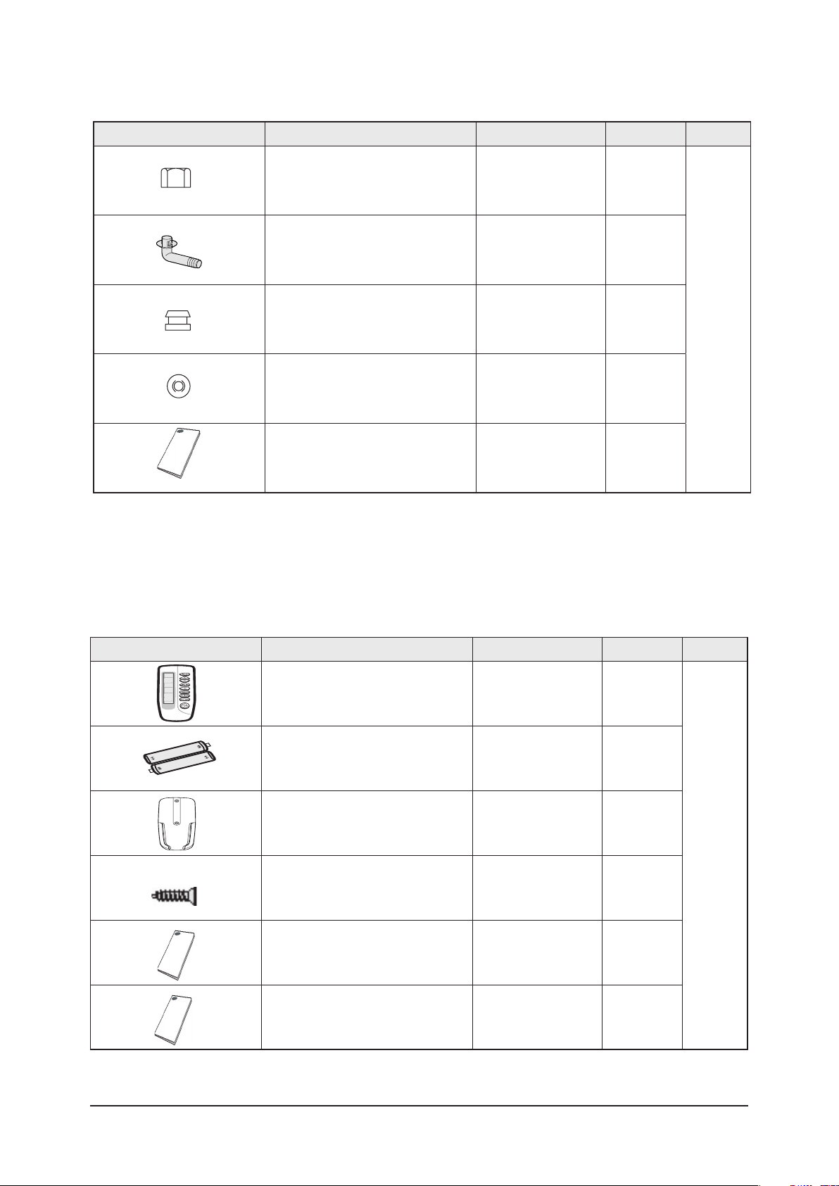
2-5 Accessory and Option Specifications
2-5-1 Accessories
Item Descriptions Code-No. Q'TY Remark
Pattern sheet DB69-01490A 1
Insulation drain
Insu Pipe Joint In 1/4 and
Insu Pipe Joint Out 1/4
Cable-tie DB65-10088C 8
Drain hose DB94-01065A 1
Pad Stopper
in/out
1/2
DB62-03440H/
DB62-03439H
DB72-00143E/
DB72-00143G
DB62-03439J 2
DB69-00165A 1
1
1
Indoor
Unit
Instruction manual
Installation manual
Safety net DB63-01480A 1
M4x12 tapped Screw
DB98-26331A 1
DB98-26330A 1
6002-2000213 4
Samsung Electronics
2-4
Samsung Electronics
Product Specifications
Accessories(cont.)
Item Descriptions Code-No. Q'TY Remark
Nut-Flare DB60-30010B 1
Rubber Bracket Wire
Installation manual
2-5-2 Accessories
Wireless Remote Controller Accessories
Item Descriptions Code-No. Q'TY Remark
Drain Plug
Cap Drain
DB67-00477A 1
DB63-10355C 1
DB73-00218A 2
DB98-26328A 1
Outdoor
Unit
Wireless remote controller DB93-00251G
Battery DB47-90024A
Remote control holder DB61-00204A
STS 2S-2x10 tapped screw 6002-000581
Owner’s instructions DB98-05156A
Installation manual DB98-05184A
1
2
1
2
1
1
2-5
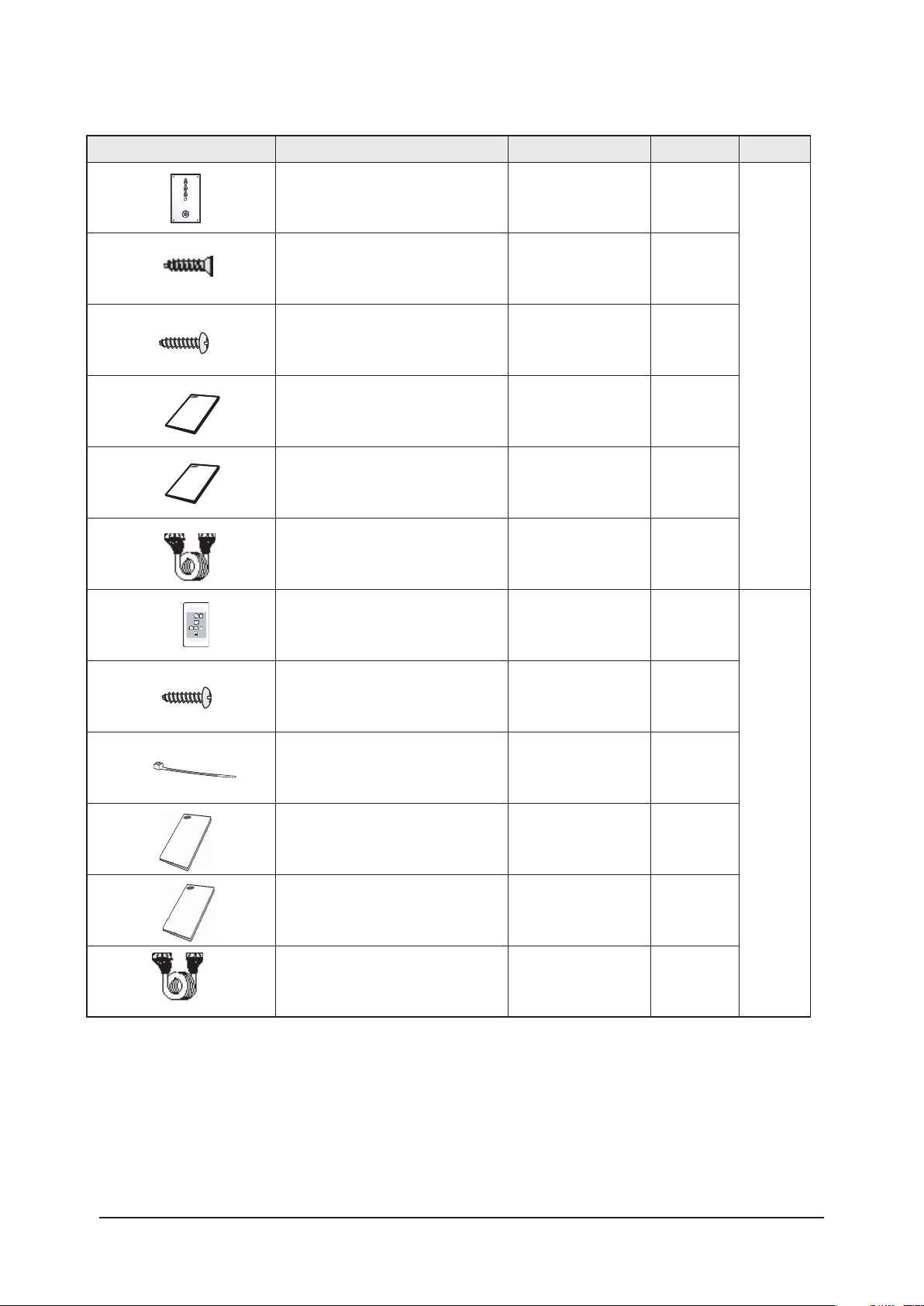
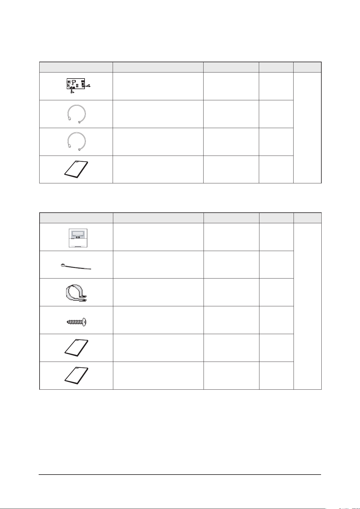
Receiver & display unit & Wire kit
Item Descriptions Code-No. Q'TY Remark
Product Specifications
Receiver & display unit DB93-01066A
STS 2S-2x10 tapped screw
2S-4x12 tapped screw
Owner’s instructions DB98-05160A
Installation manual DB98-05186A
Wire kit DB39-00223A
Receiver & display unit DB93-01066A
-
-
1
4
2
Indoor
Unit
1
1
1
5
M4x16 tapped screw
Cable-tie
Owner’s instructions DB98-05160A
Installation manual DB98-05186A
Wire kit DB39-00223A
-
-
7
2
Standard
type
1
1
1
Samsung Electronics
2-6

Samsung Electronics
Product Specifications
Wired Remote Controller Accessories
Item Descriptions Code-No. Q'TY Remark
Wired remote controller DB93-01766C
Cable-tie DB65-10088B
Cable clamp DB65-10074E
M4x16 tapped screw 6002-000474
Indoor unit power drawing cable DB39-00221A
Communication cable of the
wired remote controller
Wire joint DB39-90020A
DB39-00933A
1
2
5
7
1
1
1
Owner’s instructions DB98-15731A
Installation manual DB98-15770A
1
1
2-7
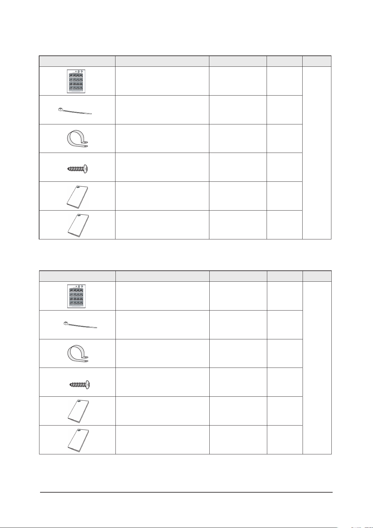
Centralized Controller Accessories
Item Descriptions Code-No. Q'TY Remark
Product Specifications
Centralized controller DB97-00874B
Cable-tie DB65-10088B
Cable clamp DB65-10074E
M4x16 tapped screw 6002-000474
Owner’s instructions DB98-12721A
Owner’s instructions DB98-12722A
1
2
5
7
1
1
Function Controller Accessories
Item Descriptions Code-No. Q'TY Remark
Function controller DB93-00757G
Cable-tie DB65-10088B
Cable clamp DB65-10074E
M4x16 tapped screw 6002-000474
Owner’s instructions DB98-05164A
Owner’s instructions DB98-05190A
1
2
6
7
1
1
Samsung Electronics
2-8
Samsung Electronics
Product Specifications
Transmitter Accessories
Item Descriptions Code-No. Q'TY Remark
7-day Scheduler Accessories
Item Descriptions Code-No. Q'TY Remark
Transmitter -
Transmitter power cable -
Transmitter communication cable -
Installation manual -
7-day Scheduler -
1
1
1
1
1
Cable-tie -
Cable clamp -
M4x16 tapped screw -
Owner’s instructions -
Installation manual -
2
2
4
1
1
2-9
3. Alignment and Adjustments
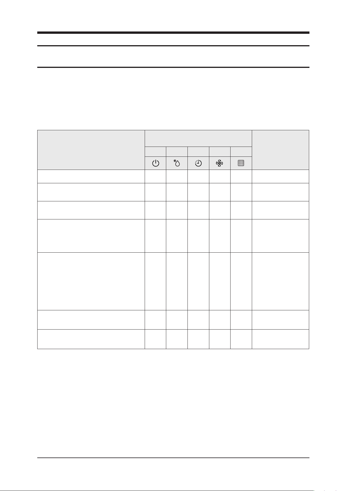
3-1 Indoor Display Error and Check Method
Error detection and reoperation
If error occurs during the operation, badness is indicated by LED flickering and all operation is stopped except LED.
When reoperating by remote control and switch determine the error mode after normal operation.
Indoor unit LED lamp display at error detecting
LED lamp display
Abnormal conditions
Power reset
Error of temperature sensor
in the indoor unit (Open/Short)
Error of heat exchanger sensor
in the indoor unit
Error of the outdoor temperature sensor
Error of the condensor temperature sensor
Error of the discharge temperature sensor
1. Error of electronic expansion valve close
2. Error of electronic expansion valve open
3. 2'nd detection of high temperature cond
4. 2'nd detection of high temperature discharge
5.Error of reverse phase
6.Compressor down due to 6'th detection of freezing
Green Red Yellow Green Orange
◑ X X X X
X X ◑ X X
◑ X ◑ X
◑ X X ◑ X
X X ◑ ◑ ◑
Remarks
Detection of the float switch
Error of setting option switches for optional
accessories
● : On ◑ : Flickering X: OFF
If you turn off the air conditioner when the LED is flickering, the LED is also turned off.
X X X ◑ ◑
X X ◑ X ◑
Samsung Electronics 3-1

3-2 Samsung Electronics
Alignment and Adjustments
LED Display
LED lamp display
Abnormal conditions
1. No communication for 2 minutes between indoor
units (Communication error for more than 2 minutes)
2. Indoor unit receiving the communication error from
outdoor unit
3. Outdoor unit tracking 3 minutes error
4.When sending the communciation error from the
outdoor unit , the mismatching of the communication
numbers and installed numbers after completion of
tracking(Communication error for more than 2 minutes)
EEPROM option error
● : On ◑ : Flickering X: OFF
If you turn off the air conditioner when the LED is flickering, the LED is also turned off.
Green Red Yellow Green Orange
X X ◑ ◑ X
◑ ◑ ◑ ◑ ◑
Remarks
OPTION ITEMS
REMOCO
MODEL
CH140EAMC 0 4 5 8 0 7 1 3 5 3 4 0
CH105EAMC
CH070EAMC
CH052EAMC
CH094EAMC 0 4 6 8 0 7 1 0 5 2 1 D
N
SEG1 SEG2 SEG3 SEG4 SEG5 SEG6 SEG7 SEG8 SEG9 SEG10 SEG11 SEG12
0 4 4 0 0 7 1 F 1 2 1 D
0 4 4 0 0 7 1 C 5 0 D B
0 4 4 0 0 7 1 B 1 0 A 8
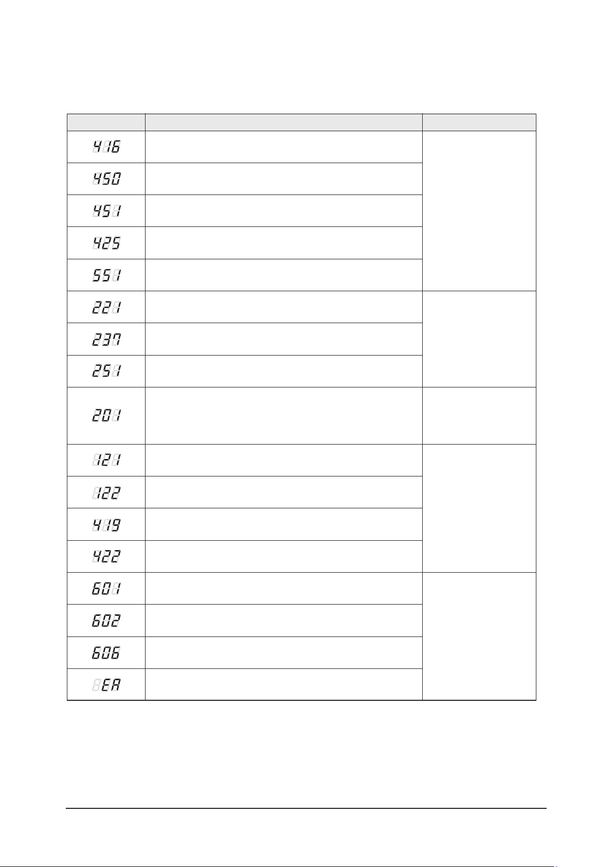
Wired Remocon Error Display
Display RemarksDescription
Compressor down due to protection control of the discharge
temperature sensor
Control due to the condenser temperature sensor when cooling mode
Error of the low pressure switch (Protection control)
Reverse phase error (Protection control)
In removing frost
Alignment and Adjustments
Error about protection
control of the outdoor unit
Error of the outdoor temperature sensor (Open/Short)
Error of condenser temperature sensor (Open/Short)
Error of discharge temperature sensor (Open/Short)
- System down caused by communication error after completion
of tracking
- Mismatching of the indoor unit numbers set with those communication
after completion of 5 times tracking
Error of temperature sensor in the indoor unit (Open/Short)
Error of the heat exchanger sensor in the indoor unit (Open/Short)
Error of electronic expansion valve open in the outdoor unit
(when it is detected more than once)
Error of electronic expansion valve close in the outdoor unit
(when it is detected more than once)
Error of communication between the indoor unit and the wired
remote controller
Error about the outdoor unit
sensor (Open/Short)
Detection during the
operation of the indoor unit
(sensing and sending errors
into the communication data)
Communication and the
indoor unit errors
Self-diagnosis of the indoor
and outdoor unit
Wired remote controller
errors
Master wired remote controlle
COM1/COM2 Cross-installed error
Error of setting option for wired remote controller COM2
r Slave wired remote controller
Samsung Electronics 3-3
3-4 Samsung Electronics
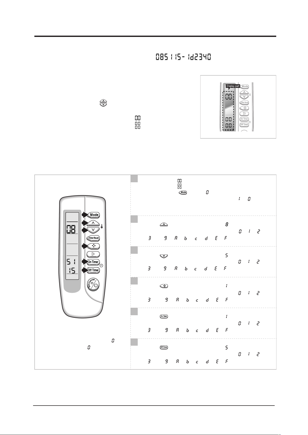
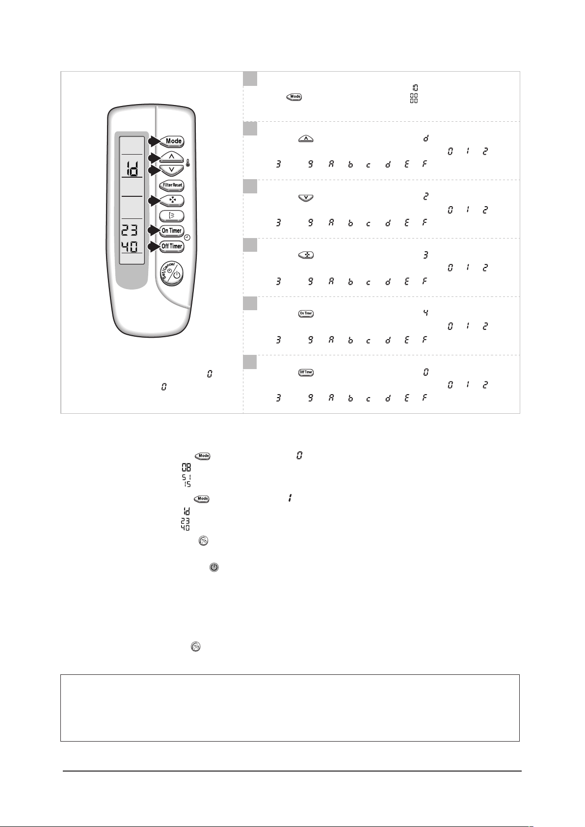
3-2 Setting Option Setup Method
1
2
3
4
5
6
ex) Option No. :
Step 1 : Enter the Option Setup mode.
1st Take out the batteries of remote control.
2
nd
Press the temperature button simultaneously and
insert the battery again.
3
Step 2 :
rd
Make sure the remocon display shown as .
Enter the Option Setup mode and select your option according to the following procedure.
1
1
The default value is .
Otherwise, push the button to
Every time you push the button, the display panel reads or
repeatedly.
2
Push the button to set the display panel to
Every time you push the button, the display panel reads
. . . repeatedly.
3
Push the button to set the display panel to
Every time you push the button, the display panel reads
. . . repeatedly.
.
.
.
4
Push the button to set the display panel to .
Every time you push the button, the display panel reads
. . . repeatedly.
5
Push the button to set the display panel to
Every time you push the button, the display panel reads
Setting is not required if you must
a value which has a default.
. . . repeatedly.
6
Push the button to set the display panel to
Every time you push the button, the display panel reads
. . . repeatedly.
.
.
7
7
8
9
10
11
12
1
Press button, then the default value is .
Setting is not required if you must
a value which has a default.
8
Push the button to set the display panel to
Every time you push the button, the display panel reads
. . . repeatedly.
9
Push the button to set the display panel to
Every time you push the button, the display panel reads
. . . repeatedly.
10
Push the button to set the display panel to
Every time you push the button, the display panel reads
. . . repeatedly.
11
Push the button to set the display panel to
Every time you push the button, the display panel reads
. . . repeatedly.
12
Push the button to set the display panel to
Every time you push the button, the display panel reads
. . . repeatedly.
.
.
.
.
.
Step 3 : Upon completion of the selection, check you made right selections.
Press the Mode Selection key, to set the display part to
and check the display part.
The display part shows .
Press the Mode Selection key, to set the display part to
and check the display part.
The display part shows .
Step 4 : Pressing the ON/OFF button
( )
When pressing the operation ON/OFF key with the direction of remote control for unit, the sound ’’Ding’’ or ’’Diriring’’
is heard and the OPERATION ICON
( ) lamp of the display is flickering at the same time, then the input of option is completed. (If
the diriring sound isn’t heard, try again pressing the ON/OFF button.)
Step 5 : Unit operation test-run
First, Remove the battery from the remote control.
Second, Re-insert the battery into the remote control.
Third,
• Error Mode
Press ON/OFF button( ) with the direction of remote control for set.
1st If all lamps of indoor unit are flickering, Plug out, plug in power plug again and press ON/OFF key to retry.
2nd If the unit is not working properly or all lamps are continuously flickering after setting the option code, see if the
correct option code is set up for its model.
Samsung Electronics 3-5

Samsung Electronics
4. Disassembly and Reassembly
Stop operation of the air conditioner and remove the power cord before repairing the unit.
4-1 Indoor Unit
CH140/105/070/052/094EAMC
No Parts Procedure Remark
1
Front Grille
- Dust-Collecting Filter
1) Push the tap on the Front Grille to open
it.
2) Disassembly of Front Grille.
(1) Open the Front Grille at about 45˚
degrees and draw it forward.
(2) Disassemble the Safety Clip.
3) Filter Disassembly
(1) Draw the Dust-Collecting Filter
forward.
(2) Disassemble the Filter.
4-1

Disassembly and Reassembly
No Parts Procedure Remark
4) Open the corner cover slowly to disassemble it. (There are three
5)
Pull the corner cover forward carefully by
using two hands.
hooks.)
6)
Loosen four bolts of the front panel
slowly.
7) Loosen four screws of the safety net to
disassemble it.
Samsung Electronics
4-2

Samsung Electronics
Disassembly and Reassembly
No Parts Procedure Remark
8) To uncover the Componet Electronic
Box cover.
(1) Loosen two screws in the mark .
(2) Draw the both side hooks toward the
arrow direction.
9) Disassemble two cables between the
indoor unit and panel.
-Stepping motor connector.
-Receiving & display unit connector wire.
10) Hold on two hooks on both sides of
the indoor unit and disassemble the Front
Panel.
11) Take away the disassembled Panel out
of the main body.
4-3
Disassembly and Reassembly
No Parts Procedure Remark
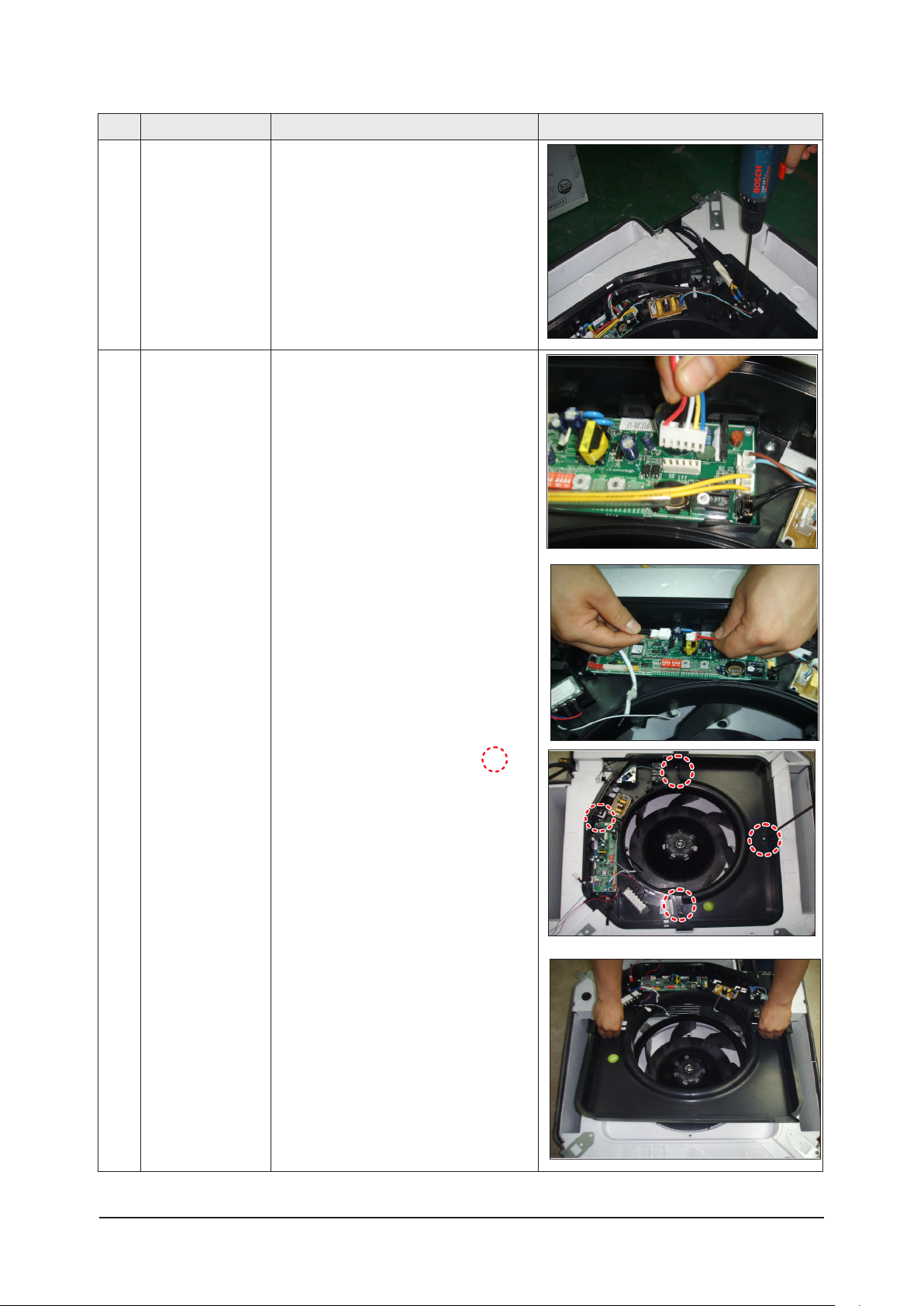
2 Electronic Part Indoor
&Outdoor Connecting
Cable
3 Fan& Motor 1) Disassemble the Fan Motor Wire
1) Disconnect all Indoor and Outdoor
Cables connected to the Terminal Board.
Connector, Thermistor Wire Connector,
Drain Pump Wire Connector and Float
Switch Wire Connector.
2) Loosen four screws in the mark .
3) Disassemble the Base Control from the
main body.
Samsung Electronics
4-4
Samsung Electronics
Disassembly and Reassembly
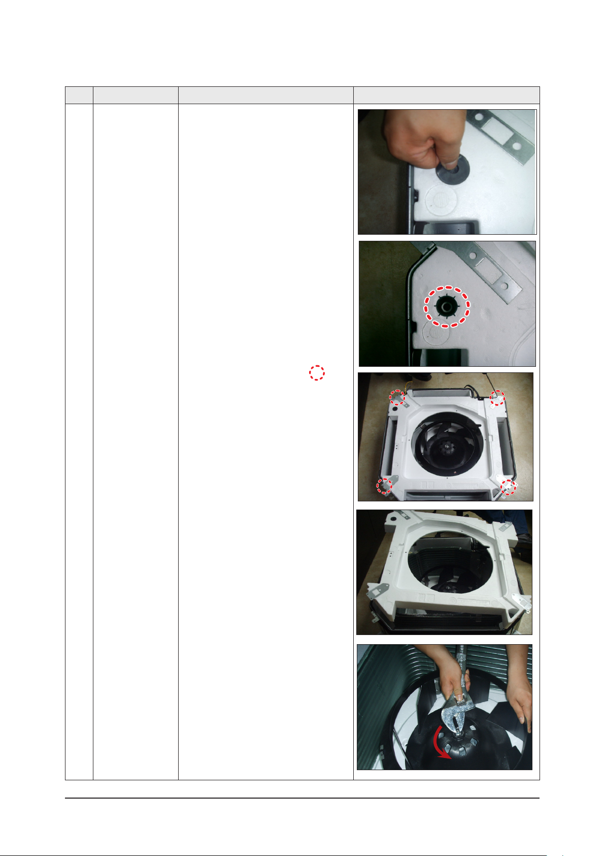
No Parts Procedure Remark
4) Disassemble the Rubber Cap Drain
Socket to remove the water on the Cushion
Drain.
(Prepare something like a gutter to put the
water in.)
* In this point, you can check the Drain
Pump Impeller operates well or not.
5) Loosen eight bolts in the mark .
* At first,
and when reassembly, there should be at
least 1 bolt per one corner fastened.
* 2 Bolts per one corner recommended..
6) Disassemble the Drain Cushion from the
main body.
7) Loosen the nut
there are 2 bolts per one corner
4-5
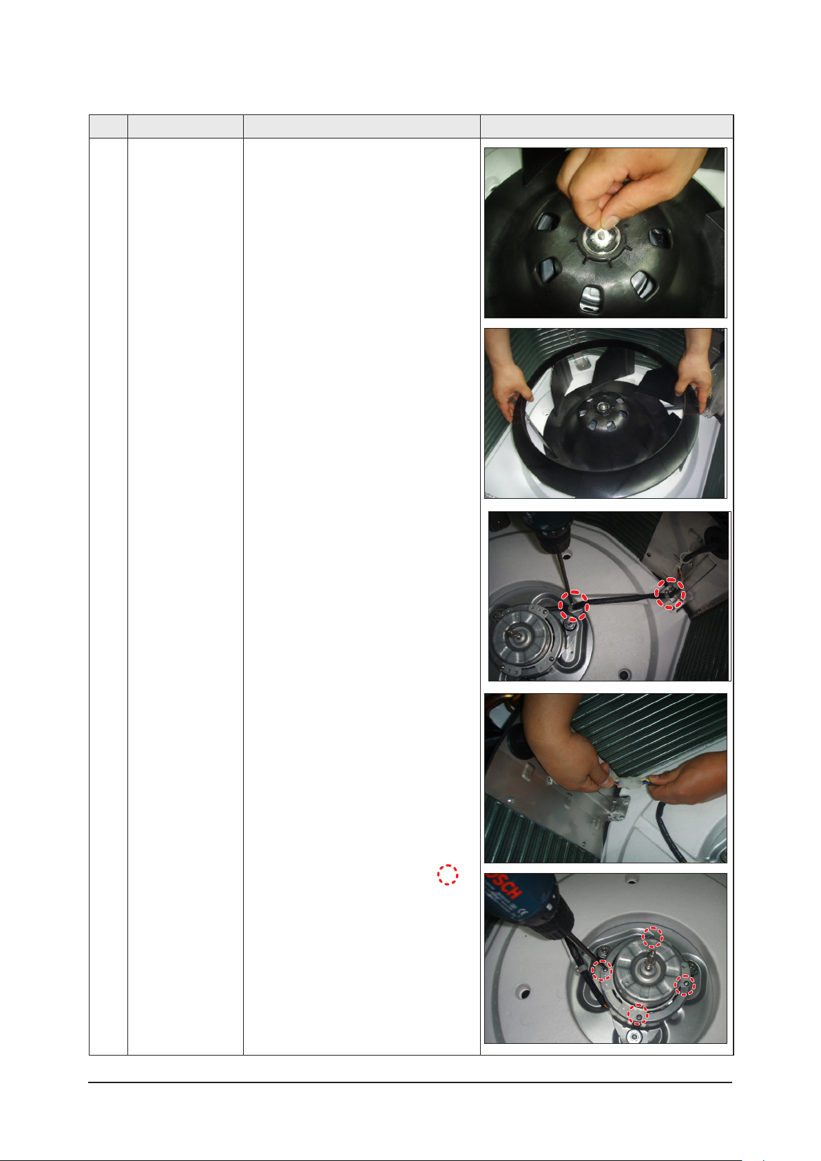
Disassembly and Reassembly
No Parts Procedure Remark
8) Take out the Washer.
9) Lift the Fan to disassemble from the
Motor.
10) Loosen the screw and disassemble the
Motor Connector to disassemble Motor.
11)Loosen four screws in the mark .
Samsung Electronics
4-6

Operating Instructions and Installation
Samsung Electronics
Disassembly and Reassembly
No Parts Procedure Remark
4 Drain Pump 1) Disassemble the Hose from the Drain
Pump.
2) Loosen the 3 bolts to disassemble the
Drain Pump from the main body.
5 Heat Exchanger 1) Loosen 2 screws to disassemble the
Cover Pipe beside the main body.
2) Loosen two screws fixing the Holder
Evap to disassemble the Heat Exchanger
.
4-64-7
Operating Instructions and Installation
Disassembly and Reassembly
No Parts Procedure Remark
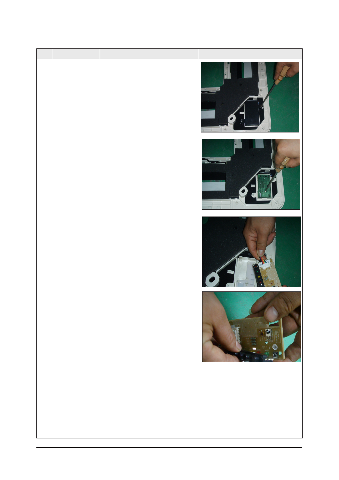
6 Front Panel
(PCB Part)
1) Loosen two screws to disassemble the
Cover PCB.
2) Loosen the screw fixing the PCB to dis
assemble it.
3) Disassemble the PCB Wire from the
PCB.
-
Samsung Electronics
4) Disassemble the Button PCB from the
PCB.
4-8
Samsung Electronics
Disassembly and Reassembly
No Parts Procedure Remark
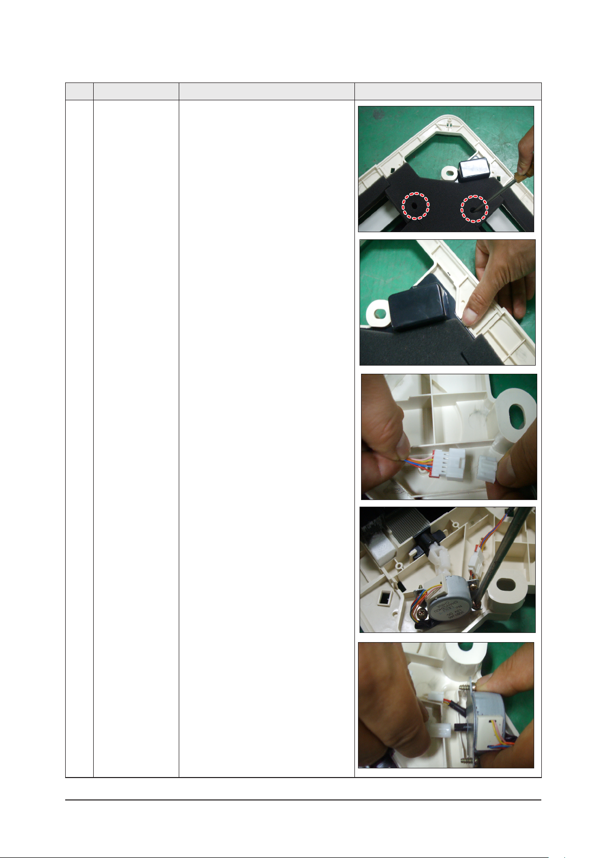
7 Panel Front
(Stepping Motor)
1) Loosen the two screws fixing the Cover
Side. (There are 4 Cover Side.)
2) Draw two hooks then lift up the Cover
Side.
3) Disassemble the Stepping Motor Wire
Connected.
4) Disassemble the Stepping Motor from the
Panel Front.
5)Disassemble the link and bracket from the
Stepping Motor.
4-9

4-2 Outdoor Unit
UH140GAMC
No Parts Procedure Remark
Disassembly and Reassembly
1 Cabinet
2 Fan Motor &
Propeller Fan
1) Turn off the equipment and disassemble
the power cable.
2) Uncover the Cabinet Top.
3) Uncover the Control Box Cover
4) Pull out the assemble Cable.
5) Disassemble the Cabinet Side
6) Disassemble the Cabinet Front.
Check whether each part is fixed to the
electronic connector firmly at the time of
part assembly.
1) Loosen the blot fixing the Propeller Fan.
2) Disassemble the Fan.
Samsung Electronics 4-10

Samsung Electronics
Disassembly and Reassembly
UH105GAMC/UH070/052EAMC,UH094EAM1C
No Parts Procedure Remark
1 Cabinet
2 Fan Motor &
Propeller Fan
1) Turn off the equipment and disassemble
the power cable.
2) Uncover the Cabinet Top.
3) Uncover the Control Box Cover
4) Pull out the assemble Cable.
5) Disassemble the Cabinet Side
6) Disassemble the Cabinet Front.
Check whether each part is fixed to the
electronic connector firmly at the time of
part assembly.
1) Loosen the blot fixing the Propeller Fan.
2) Disassemble the Fan.
Note :
The above pictures are only references
4-11
 Loading...