

Samsung BQ1VQ6T012/XEF Service Manual

OVEN
BASIC: BQ1Q4T090
MODEL: BQ1VQ6T012
MODEL CODE : BQ1VQ6T012/XEF
Manual
SERVICE
OVEN CONTENTS
1. Precaution
2. Product Specication
3. Disassembly and Reassembly
4. Troubleshooting
5. Exploded Views and Parts List
6. PCB Diagrams
7. Wiring Diagrams
8. Schematic Diagrams

Contents
1. Precaution . . . . . . . . . . . . . . . . . . . . . . . . . . . . . . . . . . . . . . . . . . . . . . . . . . . . . . . . . . . . . . . . . . . . . . . . . . . . . 1
1-1 Safety precautions . . . . . . . . . . . . . . . . . . . . . . . . . . . . . . . . . . . . . . . . . . . . . . . . . . . . . . . . . . . . . . . . . . . 1
2. Specications . . . . . . . . . . . . . . . . . . . . . . . . . . . . . . . . . . . . . . . . . . . . . . . . . . . . . . . . . . . . . . . . . . . . . . . . . . 2
2-1 Features . . . . . . . . . . . . . . . . . . . . . . . . . . . . . . . . . . . . . . . . . . . . . . . . . . . . . . . . . . . . . . . . . . . . . . . . . . . 2
2-2 Specication . . . . . . . . . . . . . . . . . . . . . . . . . . . . . . . . . . . . . . . . . . . . . . . . . . . . . . . . . . . . . . . . . . . . . . . . 3
2-3 Accessory . . . . . . . . . . . . . . . . . . . . . . . . . . . . . . . . . . . . . . . . . . . . . . . . . . . . . . . . . . . . . . . . . . . . . . . . . . 4
3. Disassembly and Reassembly . . . . . . . . . . . . . . . . . . . . . . . . . . . . . . . . . . . . . . . . . . . . . . . . . . . . . . . . . . . . . 5
3-1 Tools for Removal and Reassembly . . . . . . . . . . . . . . . . . . . . . . . . . . . . . . . . . . . . . . . . . . . . . . . . . . . . . . 5
3-2 Replacement of Case upper & Cover back . . . . . . . . . . . . . . . . . . . . . . . . . . . . . . . . . . . . . . . . . . . . . . . . 5
3-3 Replacement the Tube . . . . . . . . . . . . . . . . . . . . . . . . . . . . . . . . . . . . . . . . . . . . . . . . . . . . . . . . . . . . . . . . 6
3-4 Replacement of Door Assembly . . . . . . . . . . . . . . . . . . . . . . . . . . . . . . . . . . . . . . . . . . . . . . . . . . . . . . . . . 7
3-5 Replacement of Door Glass . . . . . . . . . . . . . . . . . . . . . . . . . . . . . . . . . . . . . . . . . . . . . . . . . . . . . . . . . . . . 8
3-6 Replacement of the rear oven Lamp Bulb . . . . . . . . . . . . . . . . . . . . . . . . . . . . . . . . . . . . . . . . . . . . . . . . 10
3-7 Replacement of the side Halogen Lamp . . . . . . . . . . . . . . . . . . . . . . . . . . . . . . . . . . . . . . . . . . . . . . . . . 10
3-8 Replacement of Assy Control Box . . . . . . . . . . . . . . . . . . . . . . . . . . . . . . . . . . . . . . . . . . . . . . . . . . . . . . 11
3-9 Replacement of Tube Steam Module . . . . . . . . . . . . . . . . . . . . . . . . . . . . . . . . . . . . . . . . . . . . . . . . . . . . 13
3-10 Replacement of Assy Steam Module . . . . . . . . . . . . . . . . . . . . . . . . . . . . . . . . . . . . . . . . . . . . . . . . . . . 15
3-11 Assembly for Main Assy Steam module part . . . . . . . . . . . . . . . . . . . . . . . . . . . . . . . . . . . . . . . . . . . . . 18
3-12 Replacement of Assy generator sub . . . . . . . . . . . . . . . . . . . . . . . . . . . . . . . . . . . . . . . . . . . . . . . . . . . 20
3-13 Replacement of Motor Fan Cooling . . . . . . . . . . . . . . . . . . . . . . . . . . . . . . . . . . . . . . . . . . . . . . . . . . . . 21
3-14 Replacement of Duct Cover, Bracket & Spring Duct & Ceramic Filter . . . . . . . . . . . . . . . . . . . . . . . . . . 21
3-15 Replacement of Motor Convection . . . . . . . . . . . . . . . . . . . . . . . . . . . . . . . . . . . . . . . . . . . . . . . . . . . . . 22
3-16 Replacement of Heater Convection twin . . . . . . . . . . . . . . . . . . . . . . . . . . . . . . . . . . . . . . . . . . . . . . . . 23
3-17 Replacement of Assy Partition S/W . . . . . . . . . . . . . . . . . . . . . . . . . . . . . . . . . . . . . . . . . . . . . . . . . . . 23
3-18 Replacement of Thermostat . . . . . . . . . . . . . . . . . . . . . . . . . . . . . . . . . . . . . . . . . . . . . . . . . . . . . . . . . 24
3-19 Replacement of Terminal Block . . . . . . . . . . . . . . . . . . . . . . . . . . . . . . . . . . . . . . . . . . . . . . . . . . . . . . . 24
3-20 Replacement of Sensor Thermistor . . . . . . . . . . . . . . . . . . . . . . . . . . . . . . . . . . . . . . . . . . . . . . . . . . . 24
3-21 Replacement of Heater Grill . . . . . . . . . . . . . . . . . . . . . . . . . . . . . . . . . . . . . . . . . . . . . . . . . . . . . . . . . . 25
3-22 Replacement of Heater Bottom . . . . . . . . . . . . . . . . . . . . . . . . . . . . . . . . . . . . . . . . . . . . . . . . . . . . . . . 25
3-23 Replacement of Assy PCB Parts (Main PCB) . . . . . . . . . . . . . . . . . . . . . . . . . . . . . . . . . . . . . . . . . . . . 26
3-24 Replacement of Assy-Door Lock . . . . . . . . . . . . . . . . . . . . . . . . . . . . . . . . . . . . . . . . . . . . . . . . . . . . . . 26
4. Troubleshooting . . . . . . . . . . . . . . . . . . . . . . . . . . . . . . . . . . . . . . . . . . . . . . . . . . . . . . . . . . . . . . . . . . . . . . . . 27
4-1 Failure Codes . . . . . . . . . . . . . . . . . . . . . . . . . . . . . . . . . . . . . . . . . . . . . . . . . . . . . . . . . . . . . . . . . . . . . . 27
5. Exploded Views and Parts List . . . . . . . . . . . . . . . . . . . . . . . . . . . . . . . . . . . . . . . . . . . . . . . . . . . . . . . . . . . . 43
5-1 Exploded Views . . . . . . . . . . . . . . . . . . . . . . . . . . . . . . . . . . . . . . . . . . . . . . . . . . . . . . . . . . . . . . . . . . . . 43
5-2 Main Parts List . . . . . . . . . . . . . . . . . . . . . . . . . . . . . . . . . . . . . . . . . . . . . . . . . . . . . . . . . . . . . . . . . . . . . 44
5-2 Main Parts List . . . . . . . . . . . . . . . . . . . . . . . . . . . . . . . . . . . . . . . . . . . . . . . . . . . . . . . . . . . . . . . . . . . . . 45
5-3 Door Parts List . . . . . . . . . . . . . . . . . . . . . . . . . . . . . . . . . . . . . . . . . . . . . . . . . . . . . . . . . . . . . . . . . . . . . 46
5-4 Control Parts List . . . . . . . . . . . . . . . . . . . . . . . . . . . . . . . . . . . . . . . . . . . . . . . . . . . . . . . . . . . . . . . . . . . 47
5-5 Standard Parts List . . . . . . . . . . . . . . . . . . . . . . . . . . . . . . . . . . . . . . . . . . . . . . . . . . . . . . . . . . . . . . . . . . 48
6. PCB Diagram. . . . . . . . . . . . . . . . . . . . . . . . . . . . . . . . . . . . . . . . . . . . . . . . . . . . . . . . . . . . . . . . . . . . . . . . . . 49
6-1 PCB Diagram . . . . . . . . . . . . . . . . . . . . . . . . . . . . . . . . . . . . . . . . . . . . . . . . . . . . . . . . . . . . . . . . . . . . . 49
7. Wiring Diagram . . . . . . . . . . . . . . . . . . . . . . . . . . . . . . . . . . . . . . . . . . . . . . . . . . . . . . . . . . . . . . . . . . . . . . . . 50
7-1 Wiring Diagram . . . . . . . . . . . . . . . . . . . . . . . . . . . . . . . . . . . . . . . . . . . . . . . . . . . . . . . . . . . . . . . . . . . . 50
8. Schematic Diagram . . . . . . . . . . . . . . . . . . . . . . . . . . . . . . . . . . . . . . . . . . . . . . . . . . . . . . . . . . . . . . . . . . . . . 51
8-1 Schematic Diagram . . . . . . . . . . . . . . . . . . . . . . . . . . . . . . . . . . . . . . . . . . . . . . . . . . . . . . . . . . . . . . . . . 51

1. Precaution
Follow these special safety precautions.
1-1 Safety precautions ( )
1. All repairs should be done in accordance with the
procedures described in this manual. This product
complies with Federal Performance Standard 21
CFR Subchapter J(DHHS).
2. Check all grounds.
3. Do not power the OVEN from a “2
Be sure that all of the built - in protective devices are
replaced. Restore any missing protective shields.
4. When reinstalling the chassis and its assemblies,
be sure to restore all protective devices including
nonmetallic control knobs and compartment covers.
5. Make sure that there are no cabinet openings
through which people --particularly children --might
insert objects and contact dangerous voltages.
6. Service technicians should remove their watches
while repairing an OVEN.
7. Design Alteration Warning:
Use exact replacement parts only, i.e., only those
that are specied in the drawings and parts lists of
this manual. Never alter or add to the mechanical or
electrical design of the OVEN. Any design changes
or additions will void the manufacturer’s warranty.
Always unplug the unit’s AC power cord from the
AC power source before attempting to remove or
reinstall any component or assembly.
- prong” AC cord.
10. Always connect a test instrument’s ground lead to
the instrument chassis ground before connecting
the positive lead; always remove the instrument’s
ground lead last.
11. Components that are critical for safety are indicated in the circuit diagram by shading,
or .
12. Use replacement components that have the same
ratings, especially for flame resistance and dielectric strength specications. A replacement part
that does not have the same safety characteristics
as the original might create shock, re or other
hazards.
NOTE: Connect the oven to a 25 A.
When connecting the oven to a 16 A,
make sure that circuit breaker can operate.
13. Never touch any circuit wiring with your hand nor
with uninsulated tool during operation.
14. For your safety, wear gloves on your hands.
15. Remove the all water from water-tank and Steam
generator, before repairing the oven set.
8. Never defeat any of the B+ voltage interlocks. Do
not apply AC power to the unit (or any of its assemblies) unless all solid-state heat sinks are correctly
installed.
9. Some semiconductor (“solid state”) devices are
easily damaged by static electricity. Such components are called Electrostatically Sensitive Devices
(ESDs). Examples include integrated circuits and
eld-effect transistors. Immediately before handling
any semiconductor components or assemblies,
drain the electrostatic charge from your body by
touching a known earth ground.
- 1 -

2. Specications
2-1 Features
BASIC MODEL
Built In Oven
Model Name BQ1Q4T090 BQ1VQ6T012
Model Type Install Single Built-in Single Built-in
Design GEO GEO
Main sales point Dual cook Dual cook
Oven Features
Cavity Interior Pyro Lytic Coating Pyro Lytic Coating
Oven Colors STSS STSS
Oven Doors (D: double, T: triple, Q: quadruple) Q Q
Door Opening Drop Down Drop Down
Interior Lamp 1(Halogen) 2(Halogen)
Interior Lights position Back/Side Back/Side
Control Method(Oven) Tact Button & Dial Tact & Touch & Dial
Display 2 Layer LED 2 Layer LED
Cleaning Method Oven Steam & Self
NEW MODEL
Built In Oven
Steam & Self &
Descaling
Heater Drop Down Fixed
Electric Features
Oven Temp Ranges - Single
- Upper or Lower 170~250 °C 170~250 °C
Grill Heater (In/Out) 1600W/1100W 1600W/1100W
Bottom Heater 1100W 1100W
Convection Heater (Upper/Lower) 1200W/1200W 1200W/1200W
Energy Class A/A/A A/A/A
Oven Function
Number of Functions 11 15
Single Mode 1. Convection Yes Yes
2. Top heat + convection Yes Yes
3. Conventional Yes Yes
4. Large Grill Yes Yes
5. Small Grill Yes Yes
6. Bottom + convection Yes Yes
40~300 °C
300 °C: Grill only
40~270 °C
270 °C: Grill only
7. Steam cook - Yes
6. Steam assist cook - Yes
- 2 -

2-1 Features
BASIC MODEL
Built In Oven
UPPER Mode 1. Convection Yes Yes
2. Top heat + convection Yes Yes
3. Large grill Yes Yes
LOWER Mode 1. Convection Yes Yes
2. Bottom heat + convection Yes Yes
3. Steam cook - Yes
4. Steam assist cook - Yes
Control Features
Clock Yes Yes
Child Safety Lock Yes Yes (Hidden)
Sound On/Off Yes (Hidden) Yes (Hidden)
Count Timer Yes Yes
Cook Time Yes Yes
End Time Yes Yes
Oven Temp Yes Yes
NEW MODEL
Built In Oven
Steam Cleaning Yes Yes
Self Cleaning Yes Yes
Language Option No No
Light On/Off Yes Yes
Sound Smart buzzer Smart buzzer
Equipment Supplied
Multi spit No No
Barbecue spit YES No
Square Baking Tray 2 2
Square Wire Rack 1 2
2-2 Specication
Specications BASIC NEWMODEL
Power source 230V 50Hz, AC 230V 50Hz, AC
Dimension
(W x H x D)
Outside 595 x 595 x 566mm 595 x 595 x 566mm
Cavity 440 x 365 x 405mm 440 x 365 x 405mm
Shipping weight Net 47Kg, Gross 52Kg Net 49Kg, Gross 55Kg
- 3 -

2-3 Accessory
The following accessories are provided with your oven.
Description Code No. Q’ty
RACK-WIRE DG59-00001A 1
RACK-WIRE ROAST DG59-00004A 1
TRAY-BAKING A DG63-00012A 1
Front
Front
TRAY-BAKING B DG63-00011A 1
ASSY-PARTITION DG97-00015A 1
STEAM-GLASS
DG01-00010A
STEAM-TRAY SUB
DG63-00246A
DG63-00242A
STEAM-TRAY
1
- 4 -
3. Disassembly and Reassembly
3-1 Tools for Removal and Reassembly
Tool
1. Tool : Nut Driver
2. Type : 7mm
3. Remarks : Heater bracket Nut
1. Tool : Nut Driver
2. Type : 9mm
3. Remarks : Convection Fan Nut
1. Tool : Longnose
2. Remarks : Tube Clamp
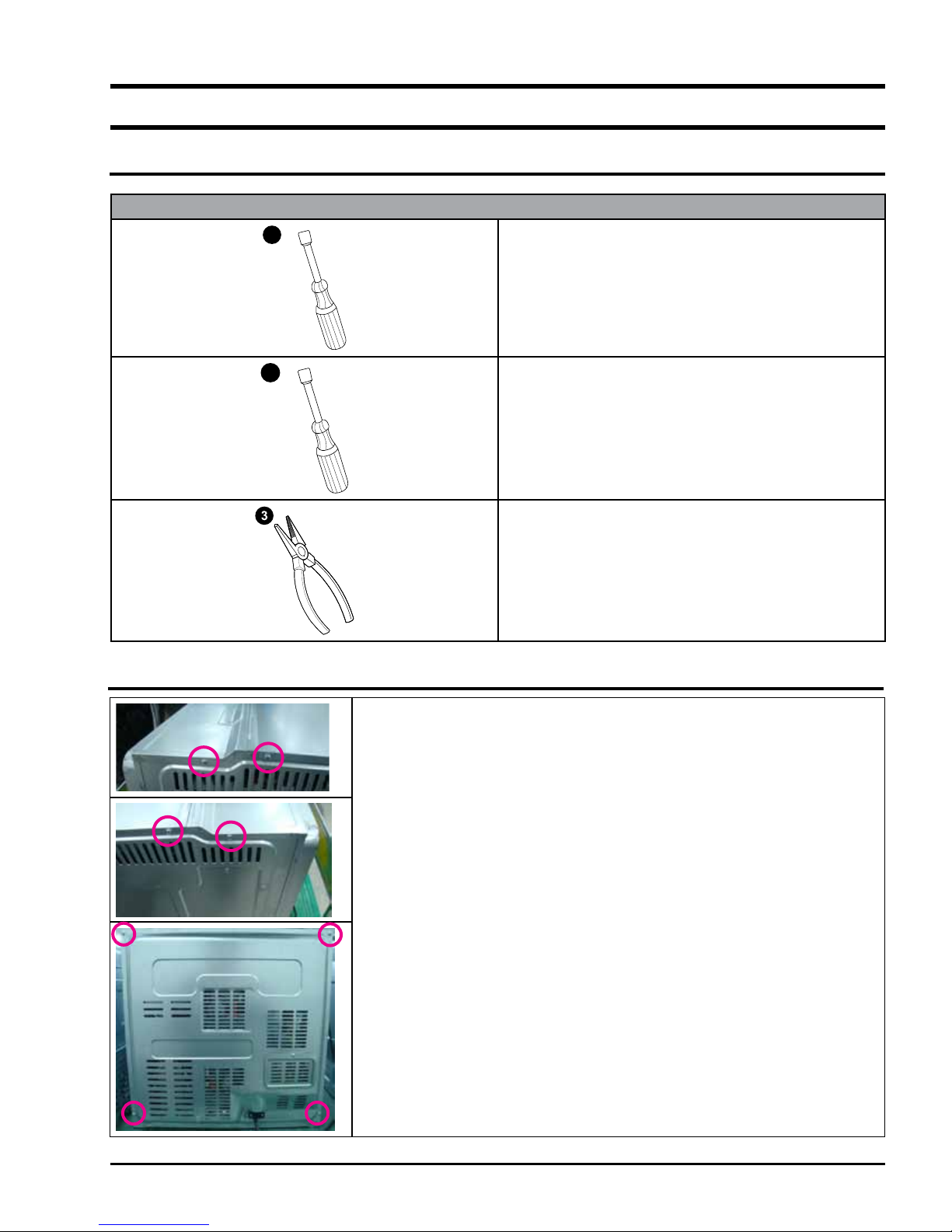
3-2 Replacement of Case upper & Cover back
* You must remove it before the repair
- 5 -

3. Disassembly and Reassembly
3-3 Replacement the Tube
The Assembly is reverse order of disjointing.
Parts Explaination Photo Explaination
1. Prepare long-nose to remove
the Tube clamp.
2. Grab the Tube clamp with longnose.
Tube
3. remove the Tube clamp.
4. remove the Tube.
- 6 -
3. Disassembly and Reassembly
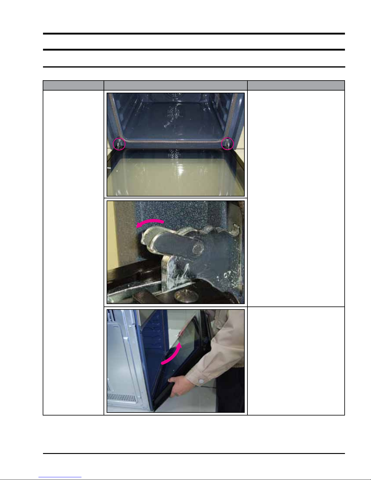
3-4 Replacement of Door Assembly
The Assembly is reverse order of disjointing.
Parts Explaination Photo Explaination
1. Turn over the clips of both
hinges.
Door Assembly
2. With both hands, grasp the
middle sides of the oven door.
3. Rotate the door by approx.
70degree until the hinges can
be taken out completely from
the hinges holes.
- 7 -
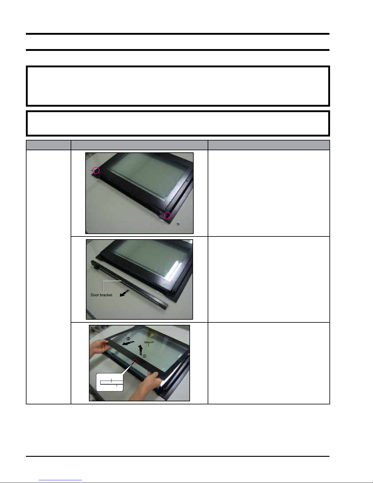
3-5 Replacement of Door Glass
The Assembly is reverse order of disjointing.
WARNING
Whenever the door is separated from the oven, the clips should always be turned over.
When the door is mounted, if some of the parts (Door glass or other parts) are removed from the door, it can
cause injury due to sheet.
ATTENTION
The glass may break if you use force especially on the edges of the front sheet.
Parts Explaination Photo Explaination
1. Remove the two screws of the left and
right sides of the door.
Door Glass
Glass #1
2. Take off the door bracket.
3. Detach the inner glass #1 (number 1)
from the door.
* When assembly the inner glass#1, put
printing to direction below.
Printing
- 8 -
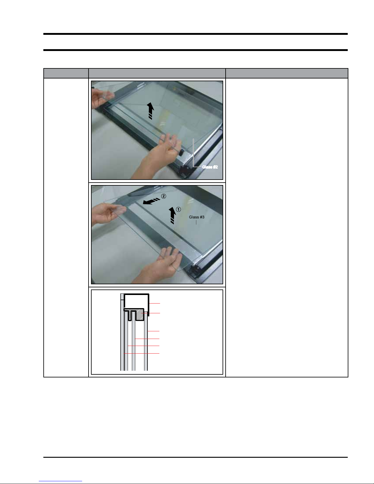
3-5 Replacement of Door Glass (Continued)
The Assembly is reverse order of disjointing.
Parts Explaination Photo Explaination
Glass #2Glass #2
Door Glass
4. Detach the inner glass #2 and springbrackets from the door.
Door Bracket
Holder Glass
Rubber
Glass #1
Glass #2
Glass #3
Glass #4
- 9 -

3-6 Replacement of the rear oven Lamp Bulb
The Assembly is reverse order of disjointing.
Parts Explaination Photo Explaination
1. Take off the cap by turning counterclockwise.
2. Remove the metal ring and the sheet ring and clean the
glass cap.
Lamp Bulb
Glass cap
Sheet ring
Metal ring
Lamp
3. If necessary, replace the bulb with a 25 watt, 230 V, 300 °C
heat - resistant oven light bulb.
4. Fit the metal and the sheet ring to the glass cap.
5. Replace the glass cap.
3-7 Replacement of the side Halogen Lamp
The Assembly is reverse order of disjointing.
Parts Explaination Photo Explaination
1. To remove the glass cover, hold the lower end with one
hand, insert a flat sharp implement such as a table knife
between the glass and the frame and pop out the cover.
2. If necessary, replace the halogen bulb with a 25 ~ 40 watt,
230 V, 300 °C heat - resistant halogen oven light bulb.
Lamp Bulb
Always use a cloth when handling a halogen bulb to
avoid depositing oils from your ngers on to the surface
of the bulb.
3. Replace the glass cover.
Tip
- 10 -

3-8 Replacement of Assy Control Box
The Assembly is reverse order of disjointing.
Parts Explaination Photo
Assy
Control Box
Assy Inlet
Pump Motor
Explaination Photo
Assy Knob Dial
Encoder Parts
Motor Fan Cooling
Assy Display
1. Remove one connector from the main
Buzzer
Assy Knob Dial
Select Parts
Door Lock
Assy PCB Parts
(Main PCB)
Explaination
pcb.
2. Remove two Tubes and one connector at
assy inlet.
3. Remove 3 screws at both sides and top
inside of assy control box, lift up assy
control box and pull forward to separate.
- 11 -
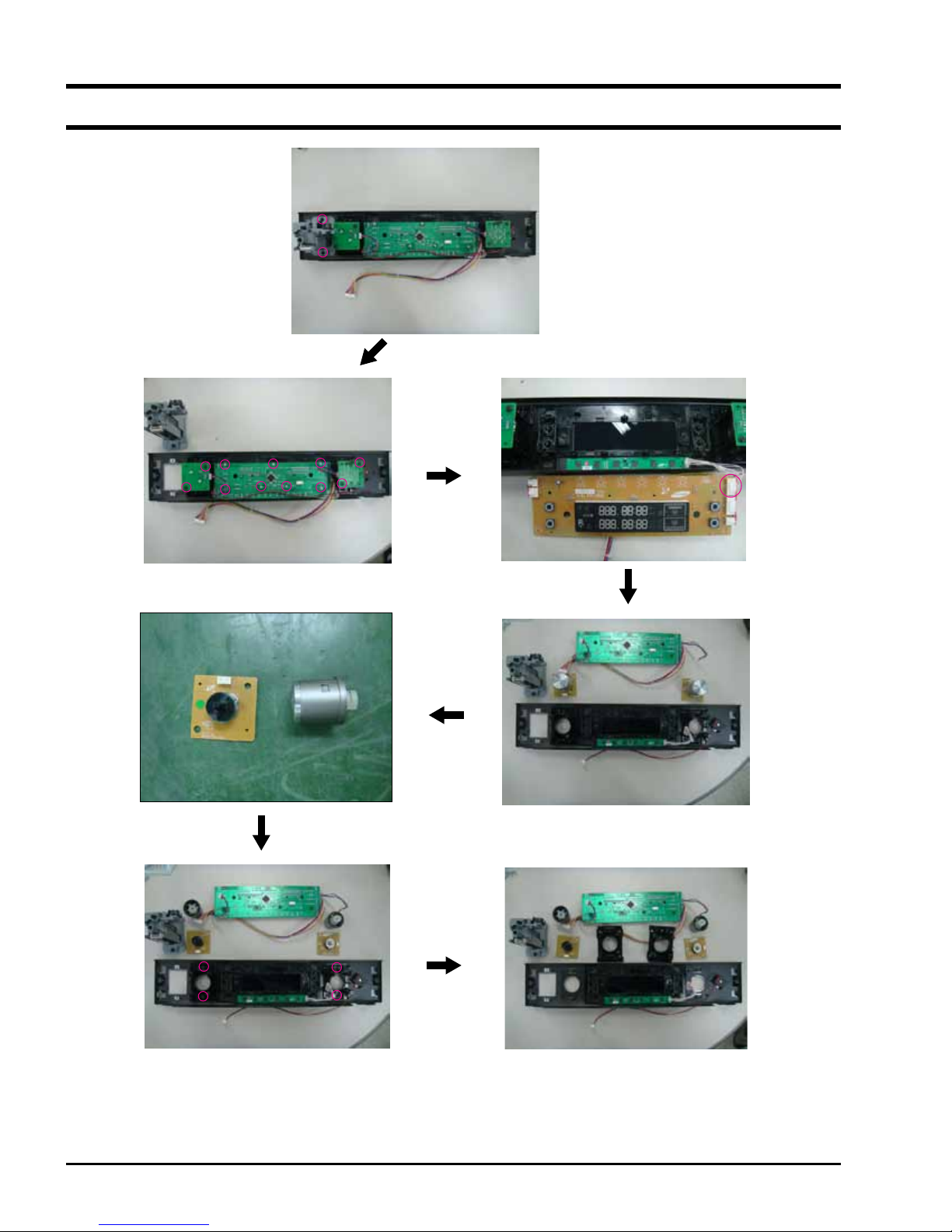
3-8 Replacement of Assy Control Box (Continued)
Remove 2 screws.
Remove 11 screws.
Remove one connector.
Remove 4 screws.
- 12 -
3-9 Replacement of Tube Steam Module
The Assembly is reverse order of disjointing.
Parts Explaination Photo Explaination
1. Remove the control-box.
2. Remove the 3 tubes.
Tube Steam
Module
3. Remove the 2 connectors and 4 hook.
4. Remove the 4 screws.
- 13 -

3-9 Replacement of Tube Steam Module (Continued)
The Assembly is reverse order of disjointing.
Parts Explaination Photo Explaination
5. Remove the Pump Motor.
Tube Steam
Module
6. Remove 2 rubbers.
- 14 -

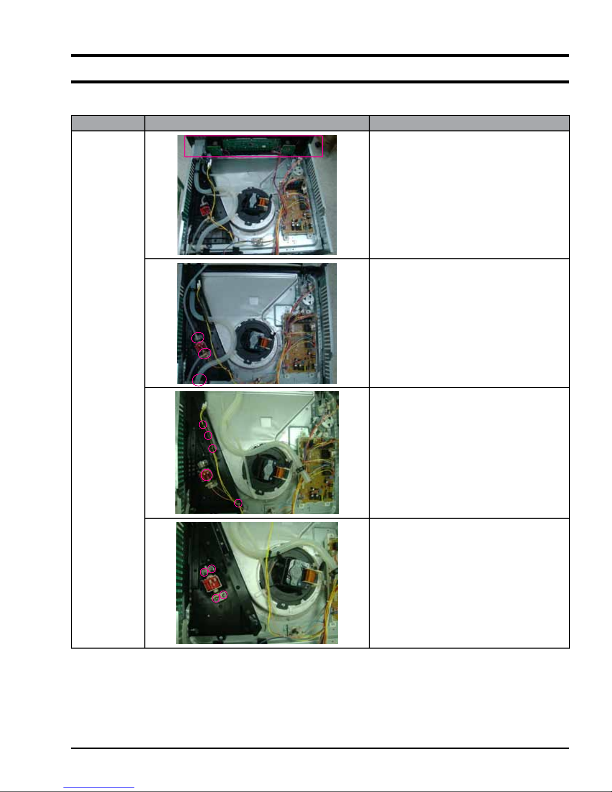
3-10 Replacement of Assy Steam Module
The Assembly is reverse order of disjointing.
Parts Explaination Photo Explaination
1. Seperate the wire-harness from the hook
on assy steam module and separate the
1 tube from assy steam generator.
2. Remove 7 connectors and 2 TCO from
the assy steam generator.
* Lower Lamp is optional.
Assy Steam
Module
3. Seperate the 2 tubes.
4. Remove 5 screws.
- 15 -
 Loading...