

SERVICE MANUAL BD-C5300
Blu-ray Disc Player
Chassis : MIDAS
BASIC : BD-C5500
Application Model
: BD-C5300
Application Area
XEF, XEN, XEU, XEE, EDC
:
If you want to know additional information which is not includ-
ed on this Service Manual, please refer to the SKP(Samsung
Knowledge Portal) web site.
Area Web Site
North America URL : http://service.samsungportal.com
Latin America URL : http://latin.samsungportal.com
CIS URL : http://cis.samsungportal.com
Europe URL : http://europe.samsungportal.com
China URL : http://china.samsungportal.com
Asia URL : http://asia.samsungportal.com
Mideast & Africa URL : http://mea.samsungportal.com
Manual
SERVICE
Blu-Ray Disc Player Contents
1. Precautions
2. Product Specification
3. Disassembly and Reassembly
4. Troubleshooting
5. Exploded View and Parts List
6. PCB Diagrams
7. Schematic Diagrams
This Service Manual is a property of Samsung Electronics Co .,Ltd.
Any unauthorized use of Manual can be punished under applicable
International and/or domestic law.
© Samsung Electronics Co., Ltd. MAR. 2010
Printed in Korea

CONTENTS CONTENTS
1. Precautions 1-1 ~ 1-7
1-1 Safety Precautions (1-2)
1-2 Servicing Precautions (1-4)
1-3 ESD Precautions (1-5)
1-4 Handling the optical pick-up (1-6)
2. Product Specication 2-1 ~ 2-11
2-1 Product Specication (2-2)
2-2 Chassis Product Specication (2-8)
2-3 Option Product Specication (2-10)
3. Disassembly and Reassembly 3-1 ~ 3-14
3-1 Cabinet and PCB (3-2)
3-2 PCB Location (3-7)
3-3 Deck (3-8)
4. Troubleshooting 4-1 ~ 4-26
4-1 Troubleshooting (4-2)
4-2 Software Update (4-24)
7. Schematic Diagrams 7-1 ~ 7-23
7-1 All Block Diagram (7-2)
7-2 Power (7-3)
7-3 S.M.P.S (S.M.P.S PCB) (7-5)
7-4 Anlog Audio (2ch)/Video (CVBS, Component)(Main PCB) (7-6)
7-5 HDMI (Main PCB) (7-8)
7-6 NAND Flash (Main PCB) (7-9)
7-7 7630 Boot Strap Option (Main PCB) (7-10)
7-8 7630 EBI_ADDR, EBI_DATA (Main PCB) (7-11)
7-9 7630 Clocks, BBS (Main PCB) (7-12)
7-10 7630 Power, Decoupling (Main PCB) (7-13)
7-11 DDR3 (Main PCB) (7-14)
7-12 Front Micom (Main PCB) (7-15)
7-13 FE_MOTOR_DRIVE (Main PCB) (7-16)
7-14 FE_OPU_CONNECTION (Main PCB) (7-17)
7-15 Ethernet, USB (Main PCB) (7-18)
7-16 GPIO Block (Main PCB) (7-19)
7-17 Main Power (Main PCB) (7-20)
7-18 VFD (VFD PCB) (7-21)
7-19 Touch Key (Touch PCB) (7-22)
5. Exploded View and Parts List 5-1 ~ 5-11
5-1 Cabinet Assembly (5-2)
5-2 Electrical Parts List (5-4)
6. PCB Diagrams 6-1 ~ 6-11
6-1 Wiring Diagram (6-2)
6-2 Main PCB (6-3)
6-3 S.M.P.S PCB (6-6)
6-4 VFD PCB (6-8)
6-5 Touch Key PCB (6-9)
6-6 USB PCB (6-10)

1. Precautions
1-1 Safety Precautions ----------------------------------------------------------------------------- 1-2
1-2 Servicing Precautions ------------------------------------------------------------------------1-4
1-3 ESD Precautions --------------------------------------------------------------------------------- 1-5
1-4 Handling the optical pick-up ------------------------------------------------------------- 1-6
Precautions
Samsung Electronics 1-1
Precautions
1-2 Samsung Electronics
1-1 Safety Precautions
1) Before returning an instrument to the customer,
always make a safety check of the entire instrument,
including, but not limited to, the following items:
(1) Be sure that no built-in protective devices are
defective or have been defeated during servicing.
(1)Protective shields are provided to protect both
the technician and the customer. Correctly replace
all missing protective shields, including any
removed for servicing convenience.
(2)When reinstalling the chassis and/or other
assembly in the cabinet, be sure to put back in place
all protective devices, including, but not limited to,
nonmetallic control knobs, insulating fish papers,
adjustment and compartment covers/shields, and
isolation resistor/capacitor networks. Do not operate
this instrument or permit it to be operated without
all protective devices correctly installed and
functioning.
(2) Be sure that there are no cabinet openings through
which adults or children might be able to insert
their fingers and contact a hazardous voltage. Such
openings include, but are not limited to, excessively
wide cabinet ventilation slots, and an improperly
fitted and/or incorrectly secured cabinet back
cover.
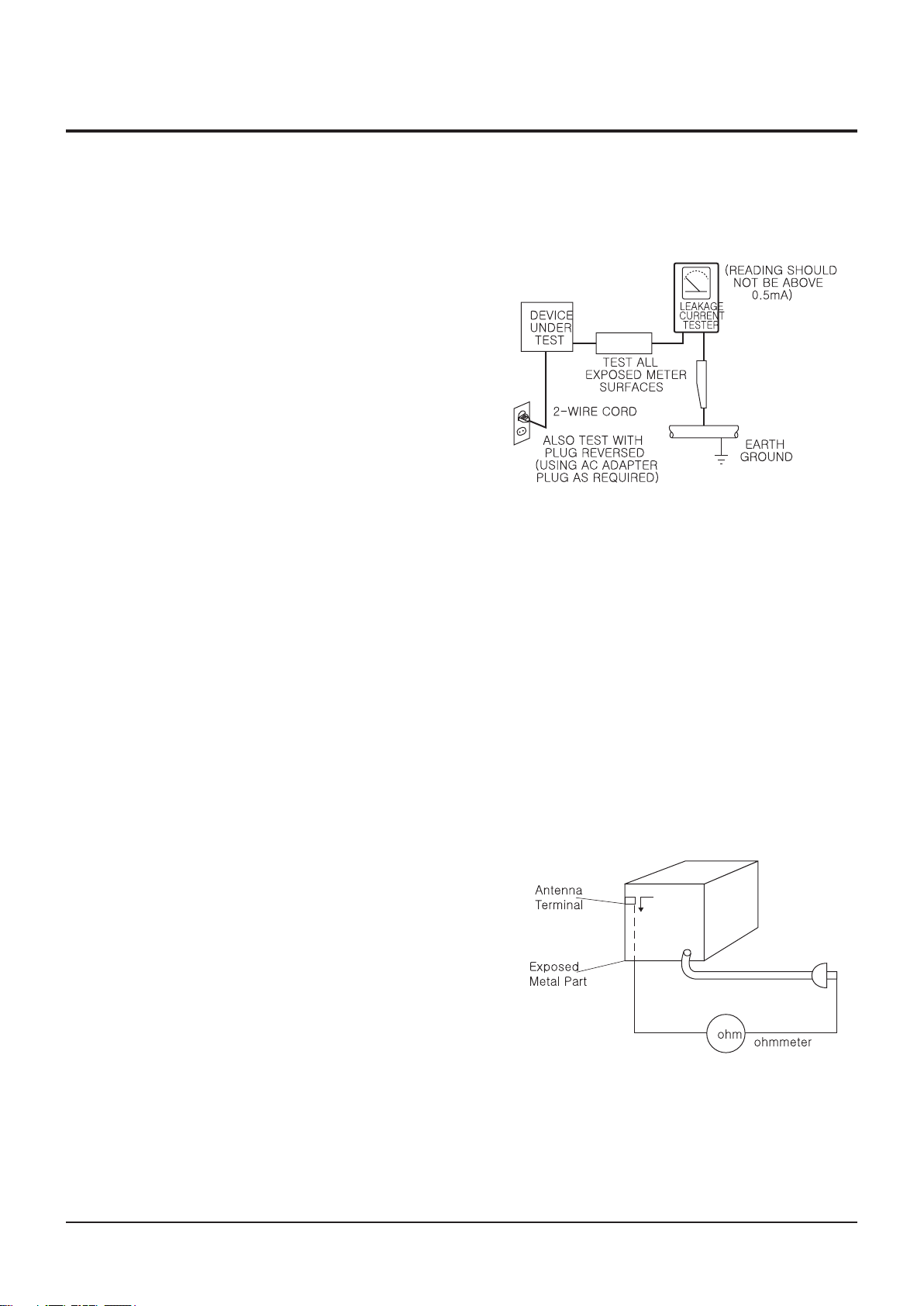
(3) Leakage Current Hot Check-With the instrument
completely reassembled, plug the AC line cord
directly into a 230V(220V ~ 240V) AC outlet. (Do
not use an isolation transformer during this test.)
Use a leakage current tester or a metering system
that complies with American National Standardsp
institute (ANSI) C101.1 Leakage Current for
Appliances and Underwriters Laboratories (UL)
1270 (40.7). With the instrument’s AC switch first in
the ON position and then in the OFF position,
measure from a known earth ground
(metal water pipe,
conduit, etc.) to all exposed metal parts of the
instrument (antennas, handle brackets, metal
cabinets,
screwheads, metallic overlays, control shafts,
etc.), especially any exposed metal parts that offer
an electrical return path to the chassis.
Any current measured must not exceed 0.5mA.
Reverse the instrument power cord plug in the outlet
and repeat the test. See Fig. 1-1.
Any measurements not within the limits specified
herein indicate a potential shock hazard that must
be eliminated before returning the instrument to
the customer.
Fig. 1-1 AC Leakage Test
(4) Insulation Resistance Test Cold Check-(1) Unplug
the power supply cord and connect a jumper wire
between the two prongs of the plug. (2) Turn on the
power switch of the instrument. (3) Measure the
resistance with an ohmmeter between the
jumpered AC plug and all exposed metallic cabinet
parts on the instrument, such as screwheads,
antenna, control shafts, handle brackets, etc. When
an exposed metallic part has a return path to the
chassis, the reading should be between 1 and 5.2
megohm. When there is no return path to the chassis,
the reading must be infinite. If the reading is
not within the limits specified, there is the possibility
of a shock hazard, and the instrument must be
repaired and rechecked before it is returned to the
customer. See Fig. 1-2.
Fig. 1-2 Insulation Resistance Test
Samsung electronics 1-2

Samsung Electronics 1-3
Precautions
2) Read and comply with all caution and safety related
notes on or inside the cabinet, or on the chassis.
3) Design Alteration Warning-Do not alter or add to
the mechanical or electrical design of this
instrument.
Design alterations and additions, including
but not limited to, circuit modications and the
addition of items such as auxiliary audio output
connections, might alter the safety characteristics of
this instrument and create a hazard to the user. Any
design alterations or additions will make you, the
servicer, responsible for personal injury or property
damage resulting therefrom.
4) Observe original lead dress. Take extra care to
assure correct lead dress in the following areas:
(1) near sharp edges, (2) near thermally hot parts (be
sure that leads and components do not touch
thermally
hot parts), (3) the AC supply, (4) high voltage,
and (5) antenna wiring. Always inspect in all areas
for pinched, out-of-place, or frayed wiring, Do not
change spacing between a component and the
printed-circuit board. Check the AC power cord for
damage.
5) Components, parts, and/or wiring that appear to
have overheated or that are otherwise damaged
should be replaced with components, parts and/ or
wiring that meet original specications.
Additionally, determine the cause of overheating
and/or damage and, if necessary, take corrective
action to remove any potential safety hazard.
6) Product Safety Notice-Some electrical and mechanical
parts have special safety-related characteristics
which are oen not evident from visual inspection,
nor can the protection they give necessarily be
obtained by replacing them with components rated
for higher voltage, wattage, etc. Parts that have
special safety characteristics are identied by
shading,
an ( )or a ( )on schematics and parts lists. Use
of a substitute replacement that does not have the
same safety characteristics as the recommended
replacement part might create shock, re and/or
other hazards. Product safety is under review
continuously and new instructions are issued
whenever appropriate.

Precautions
1-4 Samsung Electronics
1-2 Servicing Precautions
CAUTION : Before servicing units covered by this
service manual and its supplements, read and follow
the Safety Precautions section of this manual.
Note : If unforeseen circumstances create conict
between the following servicing precautions and any
of the safety precautions, always follow the safety precautions.
Remember: Safety First.
1-2-1 General Servicing Precautions
(1) a. Always unplug the instrument’s AC powercord
from the AC power source before (1) removing
or reinstalling any component, circuit board,
module or any other instrument assembly, (2)
disconnecting any instrument electrical plug or
other electrical connection, (3) connecting a test
substitute in parallel with an electrolytic capacitor
in the instrument.
b. Do not damage any plug/socket B+ voltage
interlocks with which instruments covered by
this service manual might be equipped.
c. Do not apply AC power to this instrument and
or any of its electrical assemblies unless all
solid-state device heat sinks are correctly installed.
d. Always connect a test instrument’s ground lead
to the instrument chassis ground before connecting
the test instrument positive lead. Always
remove the test instrument ground lead last.
(4) An insulation tube or tape is sometimes used and
some components are raised above the printed
wiring board for safety. e internal wiring is
sometimes clamped to prevent contact with heating
components. Install such elements as they
were.
(5) Aer servicing, always check that the removed
screws, components, and wiring have been installed
correctly and that the portion around the
serviced part has not been damaged and so on.
Further, check the insulation between the blades of
the attachment plug and accessible conductive
parts.
1-2-2 Insulation Checking Procedure
Disconnect the attachment plug from the AC outlet
and turn the power ON. Connect the insulation resistance
meter (500V) to the blades of the attachment
plug. e insulation resistance between each blade of
the attachment plug and accessible conductive
parts(see note) should be more than 1 Megohm.
Note : Accessible conductive parts include metal panels,
input terminals, earphone jacks, etc.
Note : Refer to the Safety Precautions section ground
lead last.
(2) e service precautions are indicated or printed on
the cabinet, chassis or components. When servicing,
follow the printed or indicated service precautions
and service materials.
(3) e components used in the unit have a specied
ame resistance and dielectric strength.
When replacing components, use components
which have the same. Components identied
by shading, in the circuit diagram
are important for safety or for the characteristics
of the unit. Always replace them with the exact
replacement components.

Samsung Electronics 1-5
Precautions
1-3 ESD Precautions
Electrostatically Sensitive Devices (ESD)
Some semiconductor (solid state) devices can be
damaged easily by static electricity.
Such components commonly are called Electrostatically
Sensitive Devices(ESD). Examples of typical ESD
devices are integrated circuits and some eld-eect
transistors and semiconductor chip components. e
following techniques should be used to help reduce
the incidence of component damage caused by static
electricity.
(1) Immediately before handling any semiconductor
component or semiconductor-equipped assembly,
drain o any electrostatic charge on your body by
touching a known earth ground. Alternatively,
obtain and wear a commercially available
discharging wrist strap device, which should be
removed for potential shock reasons prior to
applying power to the unit under test.
CAUTION : Be sure no power is applied to the chassis
or circuit, and observe all other safety precautions.
(8) Minimize body motions when handling
unpackaged replacement ESD devices.
(Otherwise harmless
motions such as the brushing together of your
clothes fabric or the liing of your foot from a
carpeted oor can generate static electricity
sucient to damage an ESD device).
(2) Aer removing an electrical assembly equipped
with ESD devices, place the assembly on a
conductive surface such as aluminum foil, to
prevent electrostatic
charge buildup or exposure of the assembly.
(3) Use only a grounded-tip soldering iron to solder or
unsolder ESD devices.
(4) Use only an anti-static solder removal devices.
Some solder removal devices not classied as
“anti-static” can generate electrical charges su cient to damage ESD devices.
(5) Do not use freon-propelled chemicals. ese can
generate electrical charges sucient to damage
ESD devices.
(6) Do not remove a replacement ESD device from its
protective package until immediately before
installing it. (Most replacement ESD
devices are packaged with leads electrically shorted
together by conductive foam, aluminum foil or
comparable conductive materials).
(7) Immediately before removing the protective
materials from the leads of a replacement ESD
device, touch the protective material to the
chassis or circuit assembly into which the device
will be installed.

Precautions
1-6 Samsung Electronics
1-4 Handling the optical pick-up
e laser diode in the optical pick up may suer electrostatic
breakdown because of potential static electricity from clothing and your body.
e following method is recommended.
(1) Place a conductive sheet on the work bench (e
black sheet used for wrapping repair parts.)
(2) Place the set on the conductive sheet so that the
chassis is grounded to the sheet.
(3) Place your hands on the conductive sheet(is
gives them the same ground as the sheet.)
(4) Remove the optical pick up block
(5) Perform work on top of the conductive sheet. Be
careful to let your clothes or any other static
sources touch the unit.
u Be sure to put on a wrist strap grounded to the
sheet.
u Be sure to lay a conductive sheet, that is
grounded to the table, made of copper.
Fig.1-3
(6) Short the short terminal on the PCB, which is inside
the Pick-Up ASS’Y, before replacing the Pick Up. (e short terminal is shorted when the Pick Up Ass’y is being lied or moved.)
(7) Aer replacing the Pick-up, open the short terminal
on the PCB.

Samsung Electronics 1-7
Precautions
M E M O

Product Specication
2. Product Specication
2-1 Product Specication ------------------------------------------------------------------------- 2-2
2-2 Chassis Product Specication ---------------------------------------------------------- 2-8
2-3 Option Product Specication ----------------------------------------------------------2-10
Samsung Electronics 2-1
Product Specication
2-2 Samsung Electronics
2-1 Product Specication
Weight 1.6 kg
General
Disc
Video
Output
Video/Audio
Audio
Output
Dimensions 430 (W) X 207 (D) X 43 (H) mm
Operating Temperature Range +5°C to +35°C
Operating Humidity Range 10 % to 75 %
BD Reading Speed : 4.917m/sec
DVD
(Digital Versatile Disc)
CD : 12 cm
(COMPACT DISC)
CD : 8 cm
(COMPACT DISC)
Composite Video
Component Video
HDMI
2 Channel L(1/L), R(2/R)
Digital Audio Output
*Frequency Response
*S/N Ratio 110 dB
*Dynamic Range 100 dB
*Total Harmonic Distortion
Reading Speed : 3.49 ~ 4.06 m/sec.
Approx. Play Time (Single Sided, Single Layer Disc) : 135 min.
Reading Speed : 4.8 ~ 5.6 m/sec.
Maximum Play Time : 74 min.
Reading Speed : 4.8 ~ 5.6 m/sec.
Maximum Play Time : 20 min.
1 channel : 1.0 Vp-p (75 Ω load)
Blu-ray/DVD Disc : 576i/480i
Y : 1.0 Vp-p (75 Ω load)
Pr : 0.70 Vp-p (75 Ω load)
Pb : 0.70 Vp-p (75 Ω load)
Blu-ray Disc : 1080i, 720p, 576p/480p, 576i/480i
DVD : 576p/480p, 576i/480i
1080p, 1080i, 720p, 576p/480p
PCM multichannel audio, Bitstream audio
Optical
48 kHz Sampling : 4 Hz to 22 kHz
96 kHz Sampling : 4 Hz to 44 kHz
0.003%
Samsung Electronics 2-2
Samsung Electronics 2-3
Product Specication
3 4 5 6 7 8 9 10 11 12 13 14 15
▼
PLAY MOVIE LANGUAGES SCENE SELECTIONS PREVIEWS
2-1-1 Player Features
qSupports a Variety of Disc Types
- Blu-ray (BD-ROM, BD-RE, BD-R), DVD Video, DVD-RW/-R (V mode and nalized only) discs and Audio CD.
- CD-RW/CD-R, DVD-RW/-R and USB storage device content such as MP3, JPEG and DivX les.
qHDMI (High Denition Multimedia Interface)
HDMI reduces picture noise by allowing a pure digital video/audio signal path from the player to your TV.
2-1-2 Blu-ray Disc Features
Blu-ray Discs can store 25 GB (single layer) or 50 GB (dual layer) on a single sided disc - about 5 to 10 times the
capacity of a DVD. Blu-ray Discs also support the highest quality HD video available in the industry (up to 1920 x
1080 at 40 Mbit/sec) - Large capacity means no compromise on video quality. Furthermore, a Blu-ray Disc has the
same familiar size and look as DVD.
* e following Blu-ray Disc features are disc dependant and will vary.
Appearance and navigation of features will also vary from disc to disc.
Not all discs will have the features described below.
qVideo highlights
e BD-ROM format for movie distribution supports three highly advanced video codecs, including AVC,
VC-1, and MPEG-2.
HD video resolutions are also available:
- 1920 x 1080 HD
- 1280 x 720 HD
qFor High-Denition Playback
To view high-denition contents in BD discs, an HDTV (High Denition Television) is required.Some discs
may require using the player's HDMI OUT to view high-Denition content. e ability to view
high-Denition content on BD discs may be limited depending on the resolution of your TV.
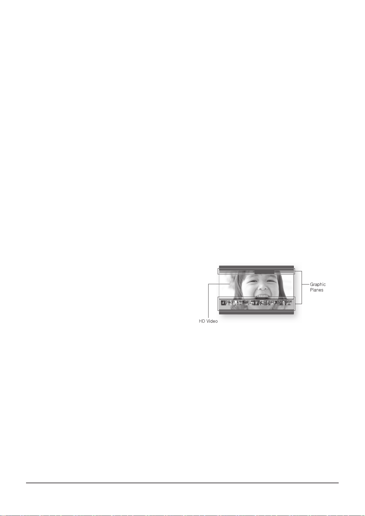
qGraphic planes
Two individual, full HD resolution (1920x1080) video layers are
available on top of the HD video layer.
One layer is assigned to video-related graphics (like subtitles),
and the other layer is assigned to interactive elements, such as
buttons or menus. Various wipes, fades and scroll eects may
be available on both layers.
qMenu graphics
Support 256 full color resolution graphics and animation, thereby greatly surpassing the capabilities of DVD-
Video. Unlike DVD, Menus can be accessed during video playback.
qMenu sounds
When you highlight or select a menu option on a Blu-ray disc, sounds can be heard such as button clicks or a
voiceover explaining the highlighted menu choice.
qMulti-page/PopUp Menus
With DVD-Video, playback is interrupted each time a new menu screen is accessed. Due to Blu-ray Disc's
ability to preload data from the disc without interrupting playback, a menu may consist of several pages.
You can browse through the menu pages or select dierent menu paths, while the audio and video remain
playing in the background.
qInteractivity
Certain Blu-ray Discs may contain Animated menus and Trivia games.
qUser Browsable Slideshows
With Blu-ray Discs, you can browse through various still pictures while the audio remains playing.
qSubtitles
Product Specication
2-4 Samsung Electronics
Depending on what is contained on the Blu-ray Disc, you may be able to select dierent font styles, sizes and
colors for the subtitles, Subtitles may also be animated, scrolled or faded in and out.
qBD-LIVE
You can use a Blu-ray Disc supporting BD-LIVE through network connection to enjoy various contents provided
by the disc manufacturer.
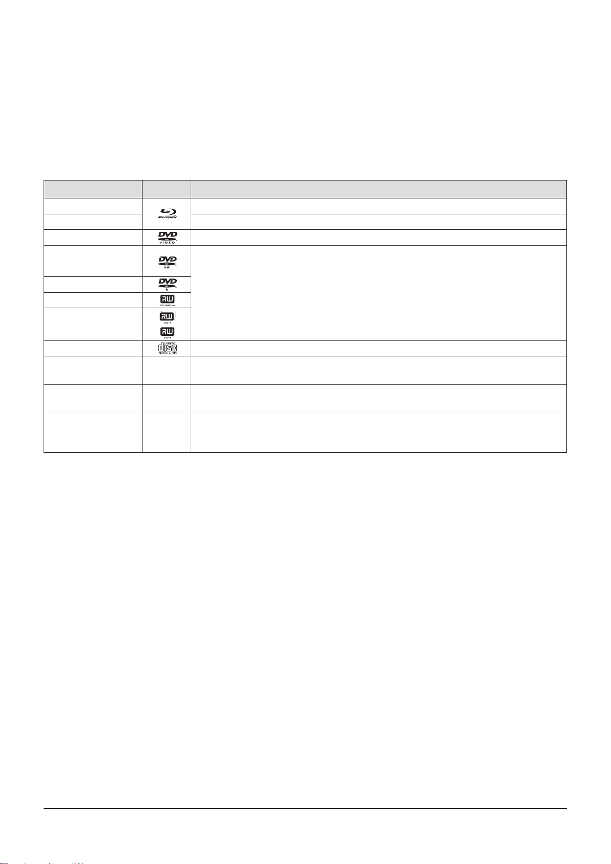
2-1-3 Disc Types and Contents that can be played
<Table 2-1>
Term Logo Denition
BD-ROM This involves a function available on a BD-ROM.
BD-RE/-R This involves a function available on a BD-RE/-R disc recorded in the BD-RE format.
DVD-VIDEO This involves a function available on a DVD-VIDEO.
DVD-RW(V)
DVD-R
DVD+RW
DVD+R
Audio CD This involves a function available on an audio CD-RW/-R (CD-DA format).
MP3
WMA
JPEG -
DivX
MKV
MP4
[Note]
r e product may not play certain CD-RW/-R and DVD-R due to the disc type or recording conditions.
rIf a DVD-RW/-R disc has not been recorded properly in DVD video format, it will not be playable.
This involves a function available on recorded DVD+RW or DVD-RW(V)/DVD-R/+R
discs that have been recorded and nalized.
This involves a function available in a CD-RW/-R, DVD-RW/-R disc or a USB storage
media containing MP3 or WMA contents.
This involves a function available in a CD-RW/-R, DVD-RW/-R disc or a USB storage
media containing JPEG contents.
This involves a function available in a CD-RW/-R, DVD-RW/-R disc or a USB storage
media containing DivX contents.
Samsung Electronics 2-5
Product Specication
2-1-4 Disc types that cannot be played
qBlu-ray Discs with a region code other than "Region A".
qDVD-VIDEO with a region number other than "1" or "ALL".
qHD DVD
qDVD-RAM
qDVD-RW(VR mode)
q3.9 GB DVD-R Disc for Authoring.
qDVD-ROM/PD/MVDisc, etc
qSuper Audio CD (except CD layer)
qCVD/CD-ROM/CDV/ CD-G/CD-I/LD (CD-Gs play audio only, not graphics.)
[Note]
r Some commercial discs and DVD discs purchased outside your region may not be playable with this product.
You may receive one of the following error messages;
either "is disc can not be played." or "Please check the regional code of the disc." will be displayed.
r Playback may not work for some types of discs, or when specic operations, such as angle change and
aspect ratio adjustment, are being performed.
Information about the discs is written in detail on the disc box. Please refer to this if necessary.
r Do not allow the disc to become dirty or scratched. Fingerprints, dirt, dust, scratches or deposits of
cigarette smoke on the recording surface may make it impossible to use the disc for playback.
r Discs with PAL programs recorded on them cannot be played using this product.
r is product is compatible with the NTSC color system only.
r When a BD-J title is played, loading may take longer than a normal title, or some functions may perform slowly.
r is product may not respond to all operating commands because some Blu-ray, DVD and CD discs allow
specic or limited operation and features during playback.
Please note that this is not a defect in the product.
r Samsung cannot assure that this product will play every disc bearing the Blu-ray Disc, DVD or CD logo
because disc formats evolve, and problems and errors may occur during the creation of Blu-ray Disc,
DVD, CD soware and/or the manufacture of discs.
Please contact the SAMSUNG customer care center if you have questions or encounter diculty in
playing Blu-ray Disc, DVD, CD discs in this product. Also, refer to rest of this user manual for additional
information on playback restrictions.
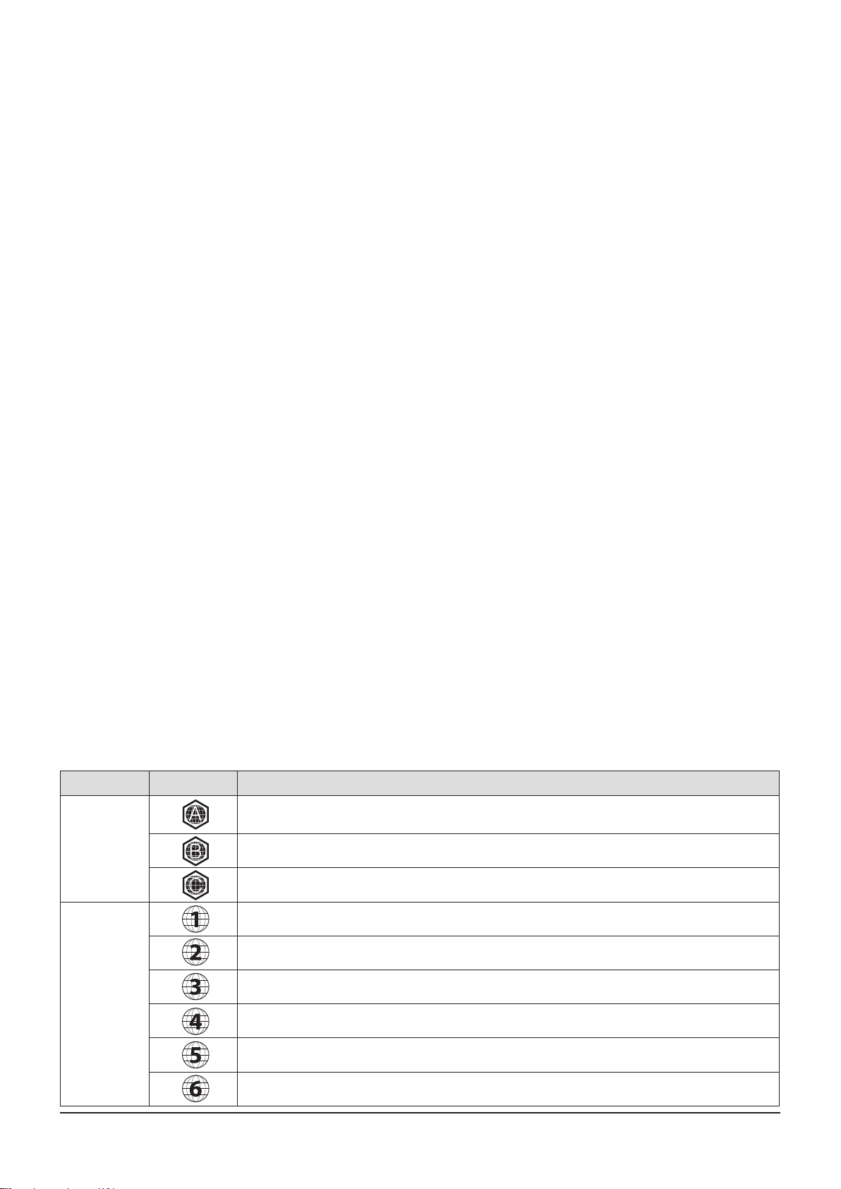
2-1-5 Region code
Both the product and the discs are coded by region. ese regional codes must match in order to play the disc.
If the codes do not match, the disc will not play.
e Region Number for this product is described on the rear panel of the product.
<Table 2-2>
Disc Type Region Code Area
North America, Central America, South America, Korea, Japan, Taiwan, Hong Kong and South East
Asia.
Blu-ray
DVD-VIDEO
Europe, Greenland, French territories, Middle East, Africa, Australia and New Zealand.
India, China, Russia, Central and South Asia.
The U.S., U.S. territories and Canada
Europe, Japan, the Middle East, Egypt, South Africa, Greenland
Taiwan, Korea, the Philippines, Indonesia, Hong Kong
Mexico, South America, Central America, Australia, New Zealand, Pacic Islands, Caribbean
Russia, Eastern Europe, India, most of Africa, North Korea, Mongolia
China

Product Specication
2-6 Samsung Electronics
2-1-6 Blu-ray Disc Compatibility
Blu-ray Disc is a new and evolving format. Accordingly, disc compatibility issues are possible. Not all discs
are compatible and not every disc will play back. For additional information, refer to the Compliance and
Compatibility Notice section of this Manual. If you encounter compatibility problems, please contact the
SAMSUNG customer care center. is Samsung Blu-ray disc player supports only the
BDROM Prole 2 (a.k.a. BD-LIVE). If you want to play later version discs, you may need to update
player's rmware. Please refer to http://www.samsung.com or contact SAMSUNG customer care center at
1-800 SAMSUNG.
2-1-7 Disc Types
qBD-ROM
- is Blu-ray disc can only be played back. is product can play back pre-recorded commercial BD-ROM discs.
qBD-RE/-R
- is Blu-ray disc can be recorded and played back.
is product can play back a BD-RE/-R disc recorded by other compatible Blu-ray disc recorders.
qDVD-VIDEO
- is product can play back pre-recorded commercial DVD discs (DVD-VIDEO discs) with movies.
- When switching from the rst layer to the second layer of a dual-layered DVD-VIDEO disc, there may be
momentary distortion in the image and sound. is is not a malfunction of the product.
qDVD-RW
- is product can play back a DVD-RW disc recorded and nalized with a DVD video recorder. Ability to
play back may depend on recording conditions.
qDVD-R
- is product can play back a DVD-R disc recorded and nalized with a DVD Video recorder.
Ability to play back may depend on recording conditions.
qDVD+RW
- is product can play back a DVD+RW disc recorded with a DVD Video recorder. Ability to
play back may depend on recording conditions.
qDVD+R
- is product can play back a DVD+R disc recorded and nalized with a DVD Video recorder.
Ability to play back may depend on recording conditions.
qAudio CD (CD-DA)
- is product can play back CD-DA format audio CD-RW/-R discs.
- e product may not be able to play some CD-RW/-R discs due to the condition of the recording.
qCD-RW/-R
- Use a 700MB(80 minutes) CD-RW/-R disc. If possible, do not use a 800MB(90 minutes) or above disc,
as the disc may not play back.
- If the CD-RW/-R disc was not recorded as a closed session, you may experience delays
when playing back the beginning of the disc or all recorded les may not play.
- Some CD-RW/-R discs may not be playable with this product, depending on the device which was used to
burn them. For contents recorded on CD-RW/-R media from CDs for your personal use, playability may vary
depending on contents and discs.
Samsung Electronics 2-7
Product Specication
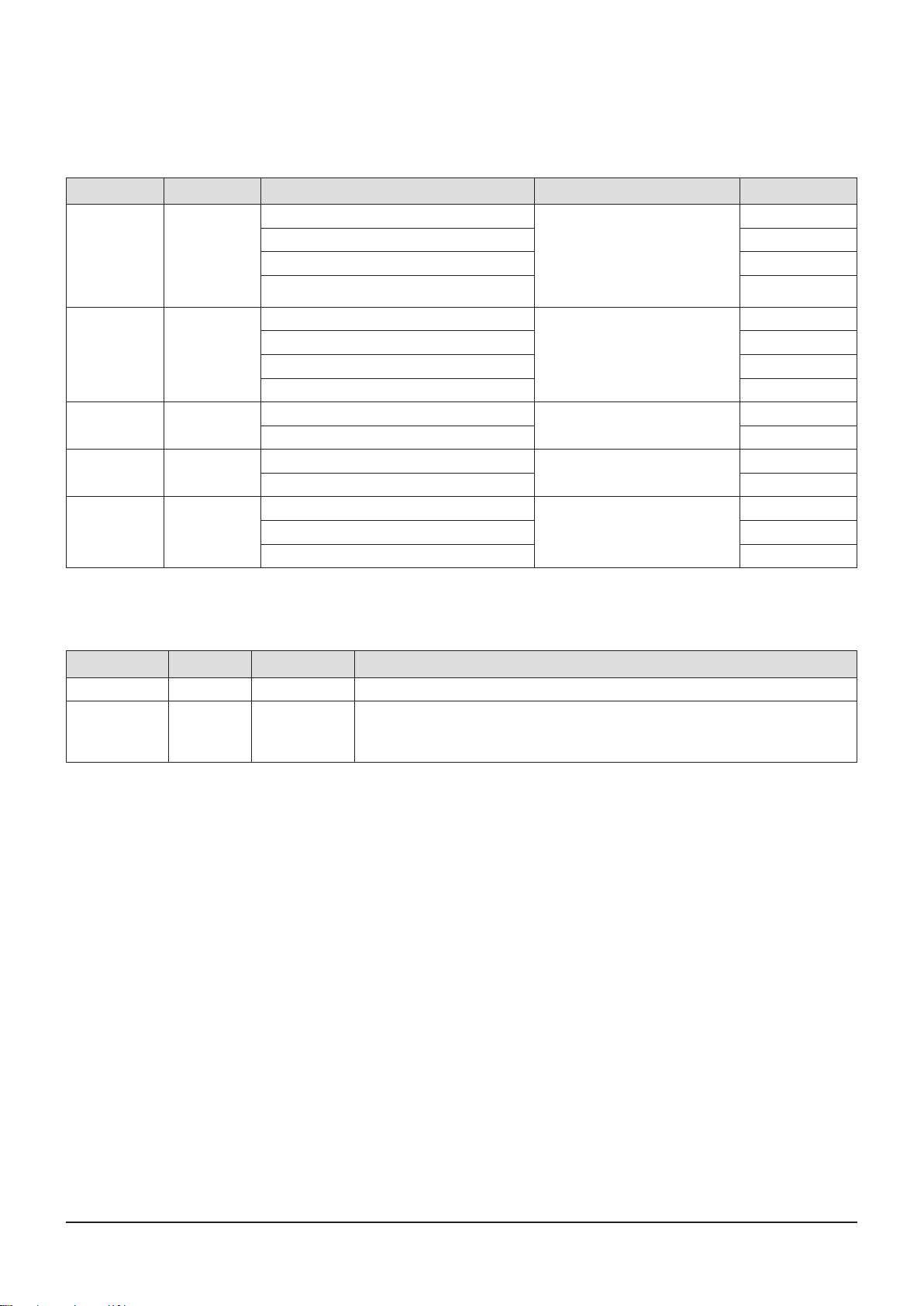
2-1-8 Supported File Formats
BRCM Video File Support
<Table 2-3>
File Extention Container Video Codec Audio Codec Resolution
*.avi AVI
*.mkv MKV
*.wmv WMV
*.mp4 MP4
*.mpg, *.mpeg PS
Divx 3.11/4.x/5.1/6.0
XviD 1920x1080
MP4v3 1920x1080
H.264 BP/MP/HP 1920x1080
VC-1 AP(wmv1)
DivX 5.1/6.0 1920x1080
XviD 1920x1080
H.264 BP/MP/HP 1920x1080
VC-1 AP
VC-1 SM 1920x1080
MP4 (mp4v)
H.264 BP/MP/HP 1920x1080
MPEG1
MPEG2 1920x1080
H.264 BP/MP/HP 1920x1080
MP3
AC3
DTS
WMA
PCM
MP3
AC3
DTS
WMA
AAC
MP1, 2
AC3
DTS
1920x1080
1920x1080
1920x1080
1920x1080
1920x1080
BRCM Music File Support
<Table 2-4>
File Extention Container Audio Codec Support Range
*.mp3 MP3 MP3 -
Compliant with WMA version 10
*.wma WMA WMA
AVCHD (Advanced Video Codec High Denition)
qis product can playback AVCHD format discs. ese discs are normally recorded and used in camcorders.
qe AVCHD format is a high denition digital video camera format.
qe MPEG-4 AVC/H.264 format is capable of compressing images at higher eciency than
that of the conventional image compressing format.
qSome AVCHD discs use the “x.v.Color” format. is product can playback AVCHD discs using “x.v.Color” format.
q“x.v.Color” is a trademark of Sony Corporation.
q“AVCHD” and the AVCHD logo are trademarks of Matsushita Electronic Industrial Co., Ltd. and Sony Corporation.
[Note]
r Some AVCHD format discs may not play, depending on the recording condition.
AVCHD format discs need to be nalized.
r “x.v.Color” oers a wider color range than normal DVD camcorder discs.
r Some DivX, MKV and MP4 format discs may not play, depending on the video resolution and frame rate condition.
* Sampling rates (in kHz) – 8, 11, 16, 22, 32, 44.1, 48
* Bit rates – All bitrates in the range 5kbps to 384kbps
Product Specication
2-8 Samsung Electronics
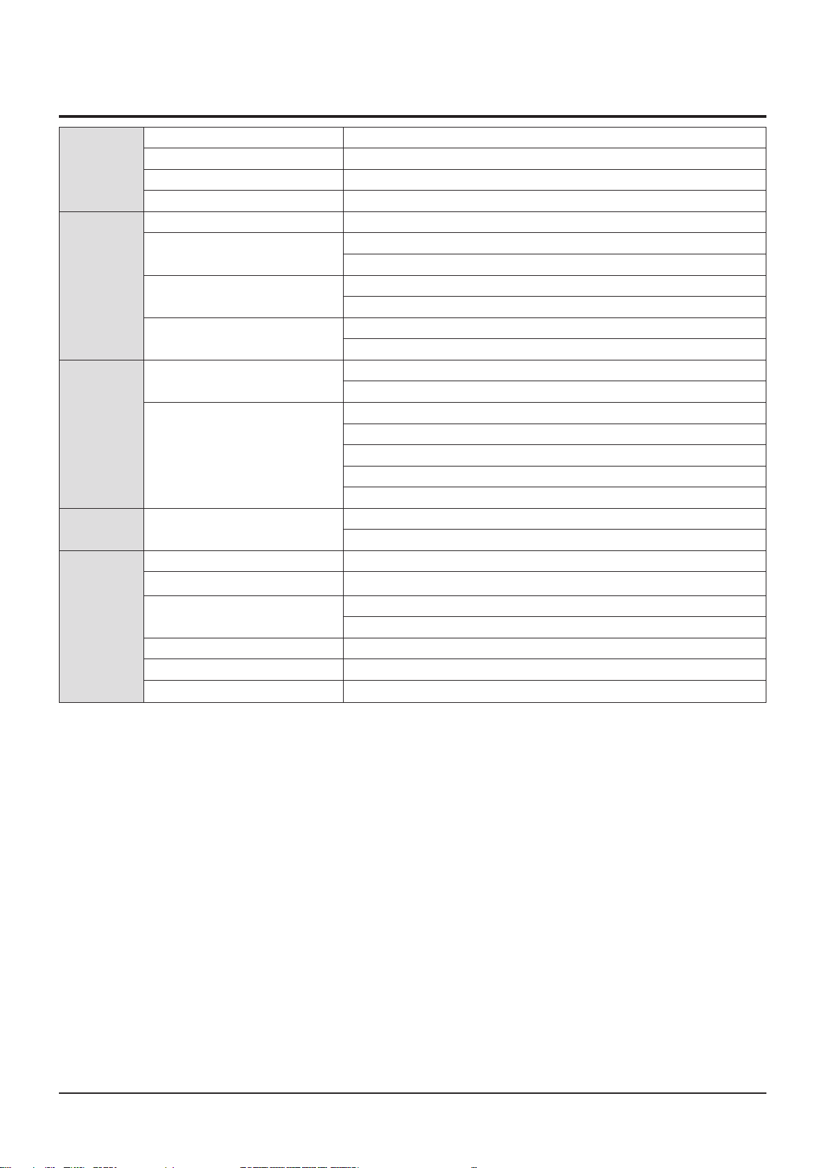
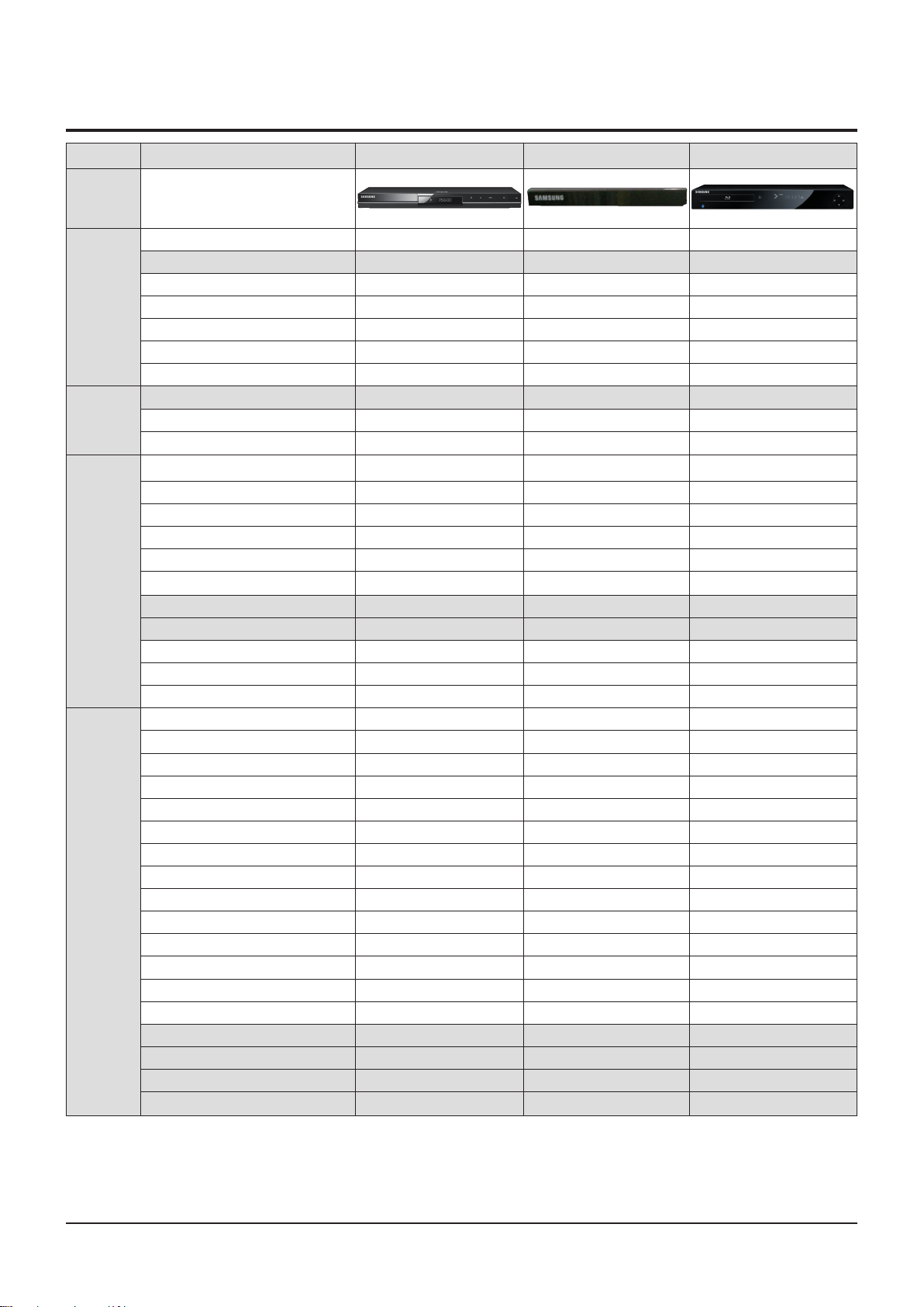
2-2 Chassis Product Specication
General Features BD-C5300 BD-P1600 BD-P1500
Chassis
CVBS Output 1 1 1
S-Video Output - - 1
Input /
Ouput
Audio/Vid-
eo Decoder
Loader
A/V Play-
able Media
YPbPr Output 1 1 1
HDMI O O O
Digital Audio Output(Optical/Coaxial) O/X O/X O/X
Analog Audio Output(2ch/7.1ch) 2ch 2ch 2ch
HDMI CEC O O O
Video Decoder(Maker : DAC) BCM7630 BCM7601 BCM7440
Video DAC 10bit 10bit 10bit
Audio DAC 24bit 192kHz 24bit 192kHz 24bit 192kHz
BD-ROM O O O
BD-RE / BD-R O O O
DVD-RAM X X X
DVD-RW O O O
DVD-ROM O O O
DVD-R O O O
DVD+R O X X
DVD+RW O X X
CD-ROM O O O
CD-R O O O
CD-RW O O O
BD-ROM O O O
BD-RE / BD-R O O O
DVD-Video O O O
DVD-Audio X X X
DVD-VR X X X
Not nalized DVD-V Mode X X X
VCD 1.1/2.0 X X X
SVCD/CVD X X X
CD-DA O O O
DTS CD O O O
HDCD X X X
SACD X X X
SACD CD Layer O O O
Picture CD O O O
mp3 O O X
JPEG O O X
DivX O X X
MKV
O X X

Samsung Electronics 2-9
Product Specication
General Features BD-C5300 BD-P1600 BD-P1500
Chassis
Front Display VFD VFD VFD
Miscellaneous
Screen capture X X X
Closed Caption pass through from disc O O O
Main Menu (including Setup Menu) O O O
O = Supported
X = Not Supported
Product Specication
2-10 Samsung Electronics
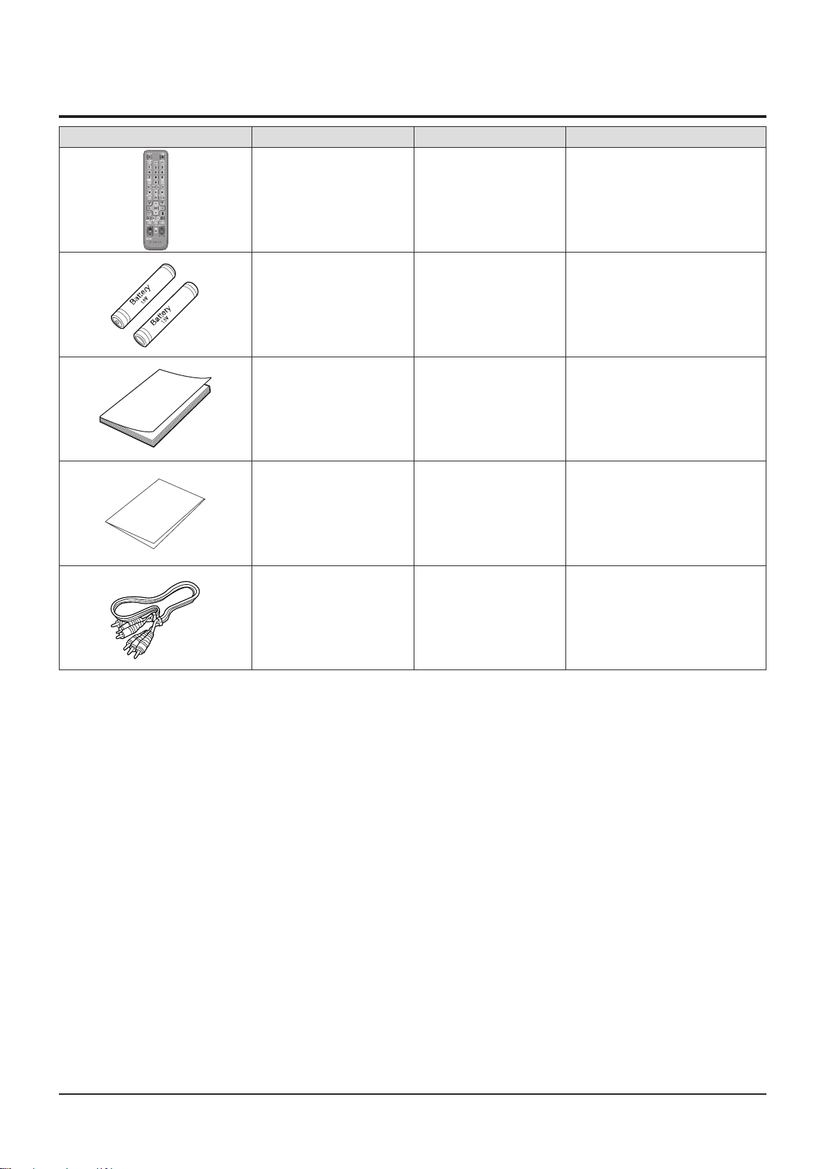
2-3 Option Product Specication
Description Fig Description Parts No Remark
Remote Control AK59-00104R
Batteries for Remote Control
(AAA Size)
User Manual AK68-01941Q
Quick Guide AK68-01855A
AC43-12002H
Model Standard of
BD-C5300/XEF
Model Standard of
BD-C5300/XEF
S.N.A
Model Standard of
BD-C5300/XEF
Model Standard of
BD-C5300/XEF
S.N.A
Audio/Video cable AC39-00073A
Model Standard of
BD-C5300/XEF

Samsung Electronics 2-11
Product Specication
M E M O

Disassembly and Reassembly
3. Disassembly and Reassembly
3-1 Cabinet and PCB ---------------------------------------------------------------------------------3-2
3-2 PCB Location --------------------------------------------------------------------------------------- 3-7
3-3 Deck ----------------------------------------------------------------------------------------------------- 3-8
Samsung Electronics 3-1
Disassembly and Reassembly
3-2 Samsung Electronics
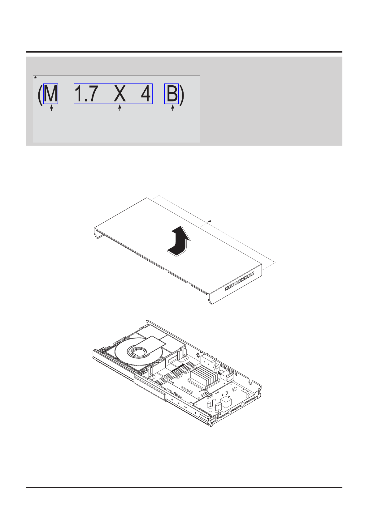
(SCREW TYPE)
M : MACHINE
T : TAPTYPE
(SCREW SIZE)
M1.7 x L9
(SCREW COLOR)
B : Black
W : White
S : Silver
SCREW SIZE INFORMATION
3-1 Cabinet and PCB
CAUTION : Connector Must be removed with care
3-1-1 Top Cabinet Removal
1) Remove 3 Screws q.
2) Li up the Top Cabinet
w in direction of arrow.
q 3 SCREWS
(M 3 X 10 B)
w TOP CABINET
Samsung Electronics 3-2
Fig. 3-1 Top Cabinet Removal
Samsung Electronics 3-3
Disassembly and Reassembly
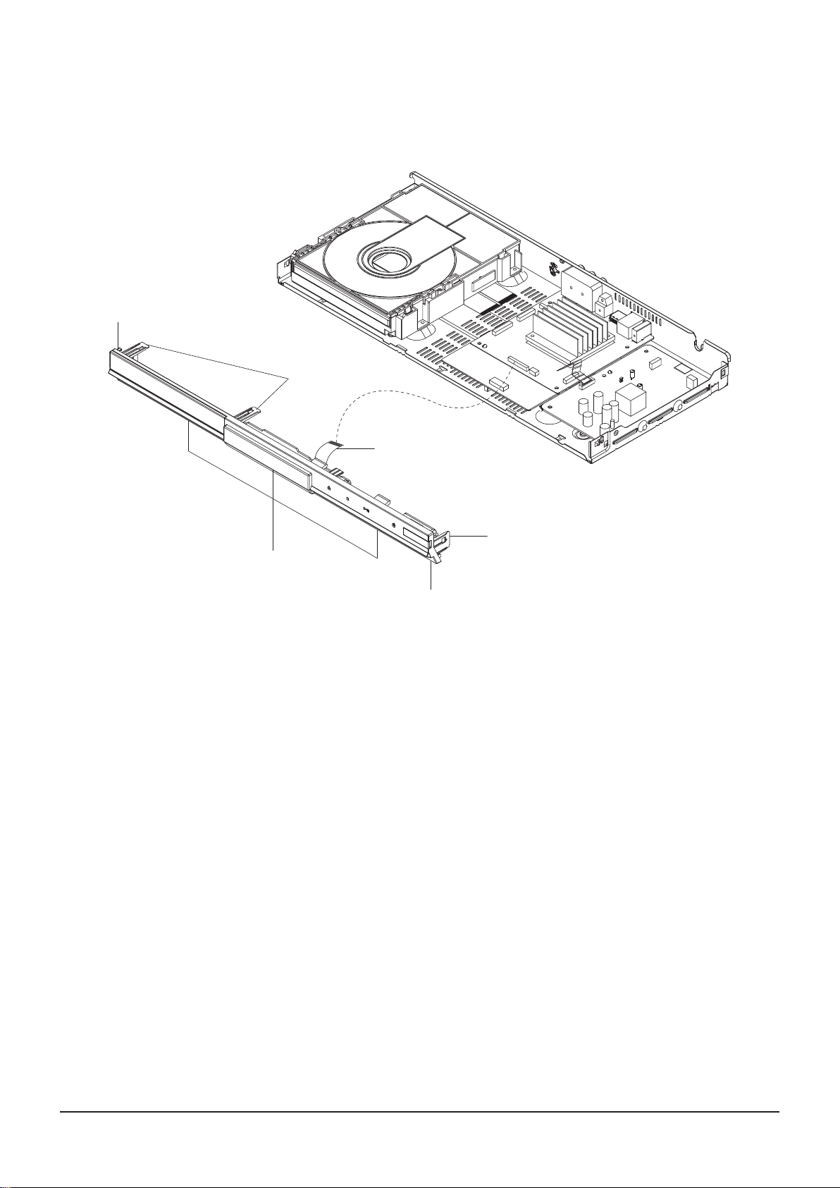
3-1-2 Ass'y Front-Cabinet Removal
1) Remove FFC Cable q from the Main PCB.
2) Remove 7 Hooks
w, e, r, t and Ass'y Front-Cabinet y.
w 1 HOOK
t 2 HOOKS
q FRONT FFC CABLE
r 3 HOOKS
e 1 HOOK
y ASS'Y FRONT-CABINET
Fig. 3-2 Ass'y Front-Cabinet Removal
Disassembly and Reassembly
3-4 Samsung Electronics
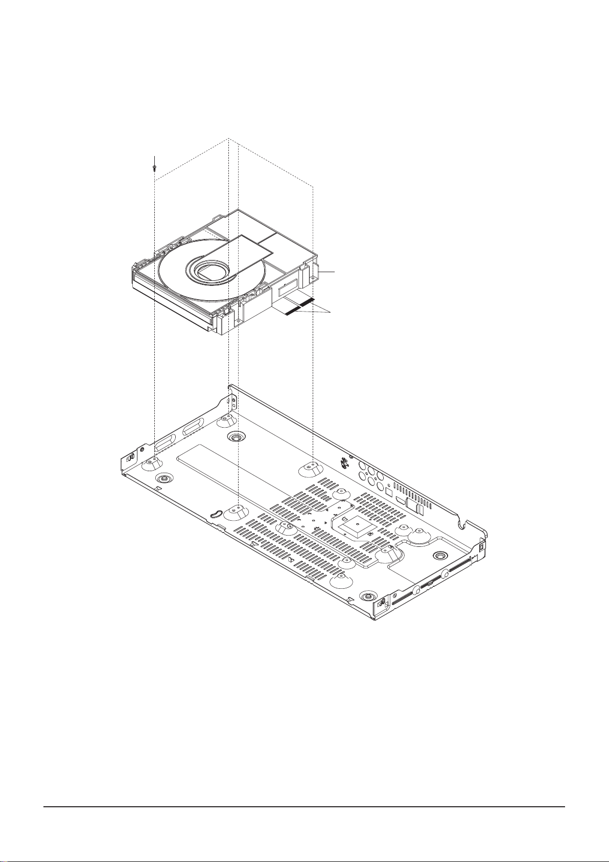
3-1-3 Ass'y Deck Removal
1) Remove 4 Screws q Disconnect FPC Cable w from the Main PCB.
2) Remove Ass'y Deck e and li it up.
q 4 SCREWS
(M 3 X 6 W)
e ASS'Y DECK
w FPC CABLE
Fig. 3-3 Ass'y Deck Removal
Samsung Electronics 3-5
Disassembly and Reassembly
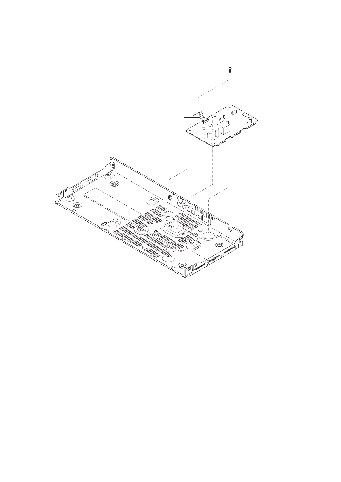
3-1-4 S.M.P.S PCB Removal
1) Remove 3 Screws q Disconnect FPC Connector w from the Main PCB.
2) Remove S.M.P.S PCB e and li it up.
q 3 SCREWS
(M 3 X 6 W)
w FPC CONNECTOR
e S.M.P.S PCB
Fig. 3-4 S.M.P.S PCB Removal
Disassembly and Reassembly
3-6 Samsung Electronics
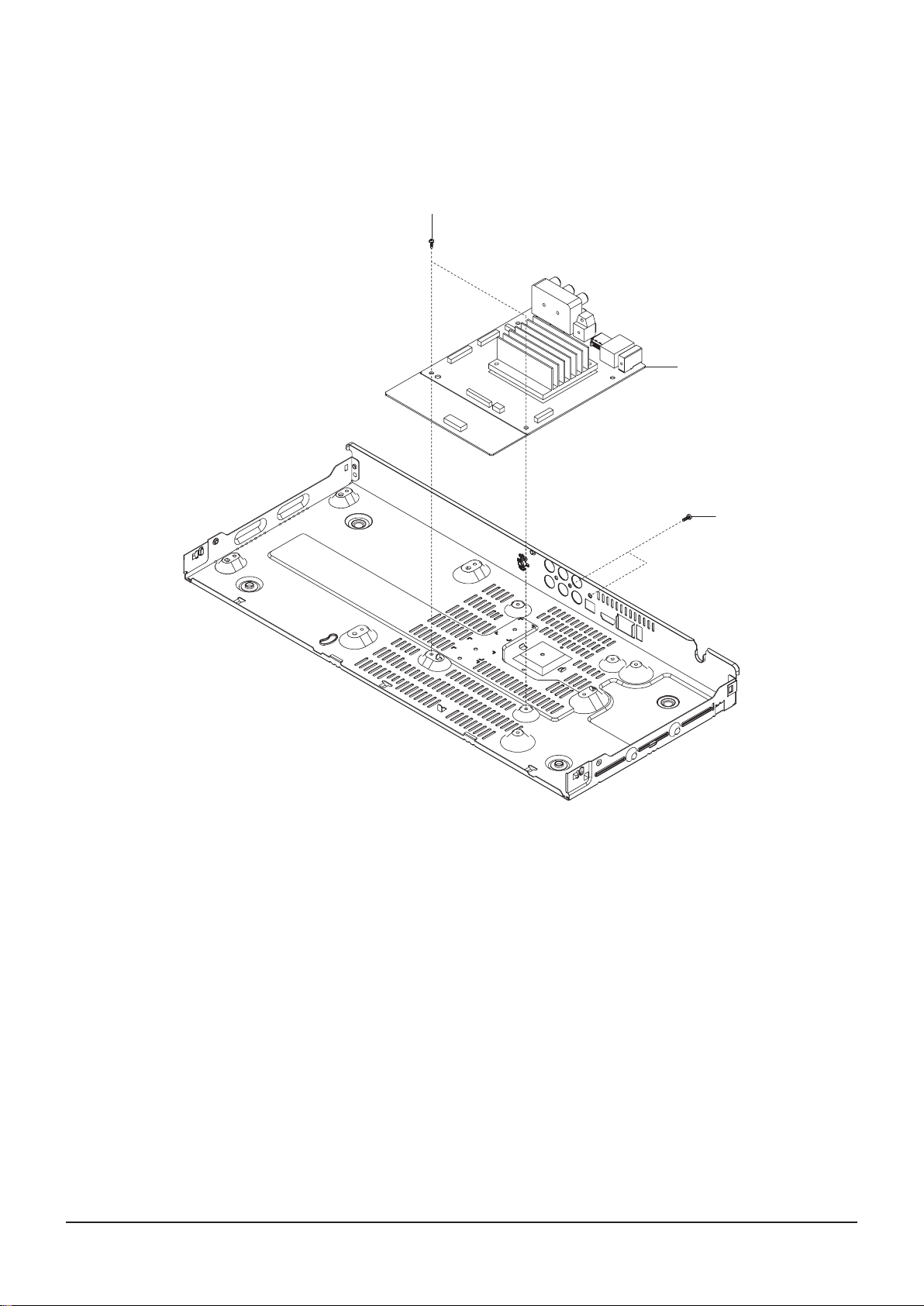
3-1-5 Main PCB Removal
1) Remove 4 Screws q, w from the Main PCB e and li it up.
q 2 SCREWS
(M 3 X 6 W)
e MAIN PCB
Fig. 3-5 Main PCB Removal
w 2 SCREWS
(M 3 X 10 B)
Samsung Electronics 3-7
Disassembly and Reassembly
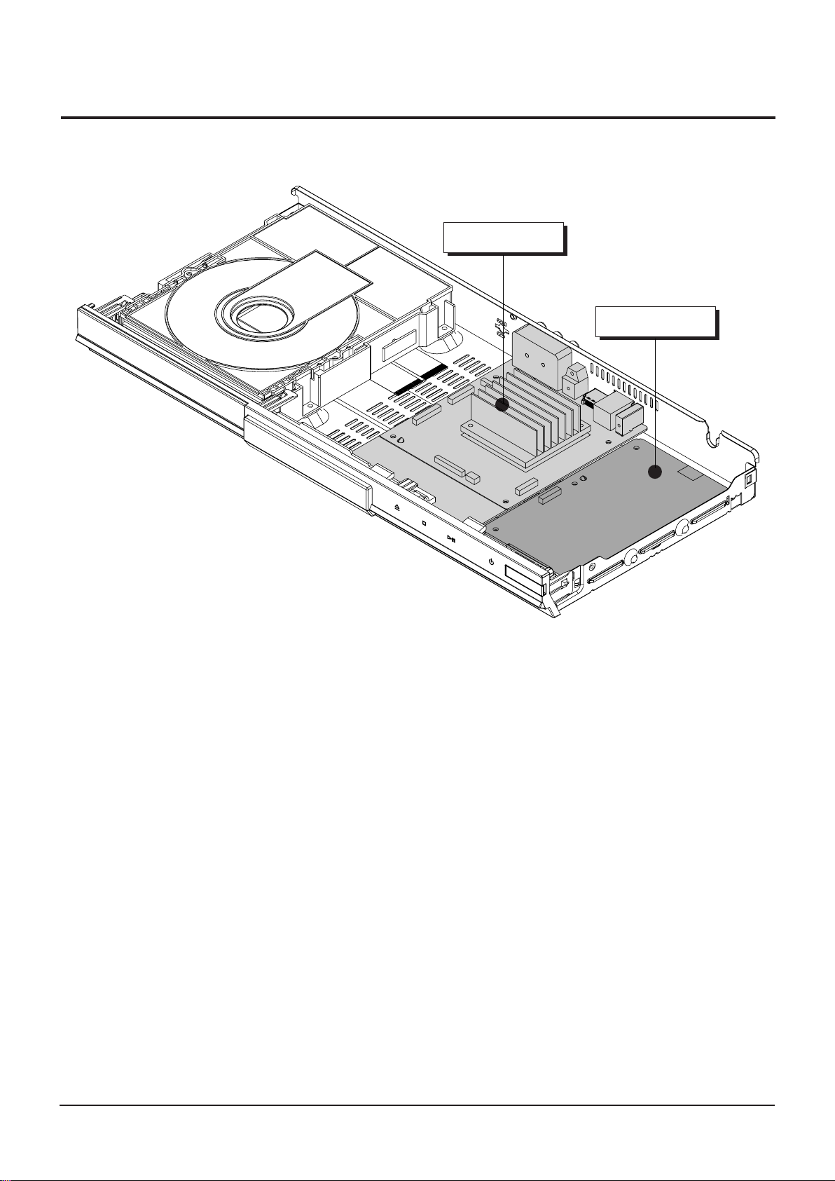
3-2 PCB Location
MAIN PCB
S.M.P.S PCB
Fig. 3-6 PCB Location
Disassembly and Reassembly
3-8 Samsung Electronics
3-3 Deck
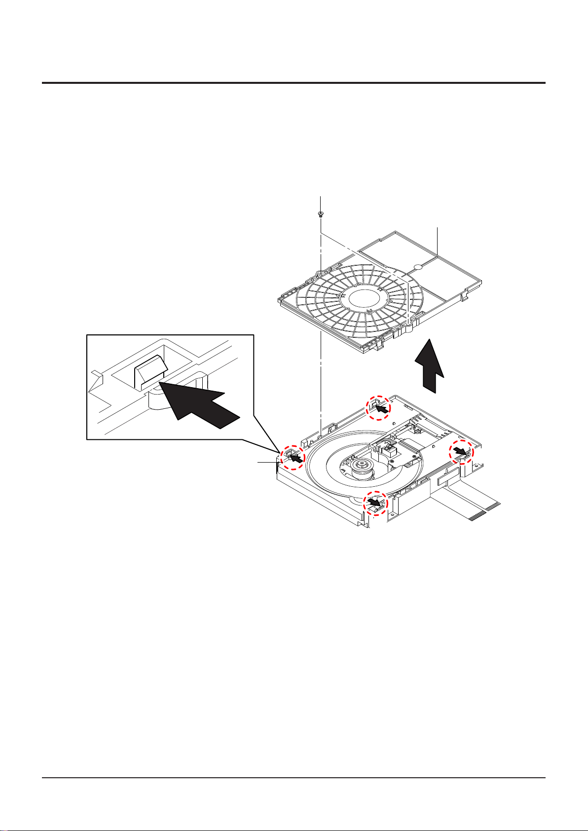
3-3-1 Ass'y Cover Removal
1) Remove 2 Screws q.
2) Push 4 Hooks
3) Li up the Ass'y Cover
w in the Direction of Arrow "A".
e in direction of arrow "B".
q 2 SCREWS
(M 2 X 7 W)
e ASS'Y COVER
w 4 HOOKS
Fig. 3-7 Ass'y Cover Removal
"A"
"A"
"A"
"B"
"A"
Samsung Electronics 3-9
Disassembly and Reassembly
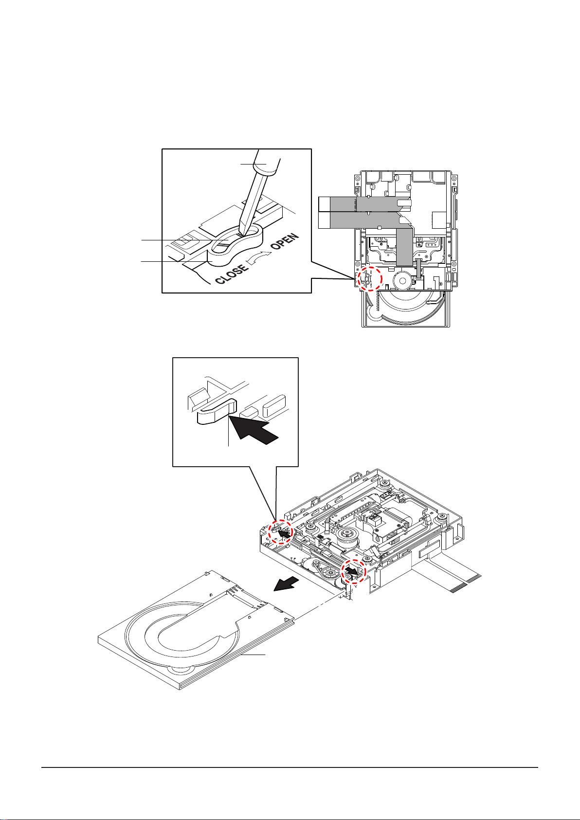
3-3-2 Tray Disc Removal
1) Insert a Screw Driver into Hole q and rotate Gear Tray w in the direction arrow "Open".
2) When the Tray Disc e Comes out a little, pull it in the direction arrow "A" by hand.
3) Pull the Tray Disc e to disassemble, while simultaneously pushing 2 Stoppers r (le, right)
in the direction arrow "B", "C".
SCREW DRIVER
w GEAR TRAY
q HOLE
r STOPPER
(BOTTOM VIEW)
"B"
"A"
"C"
e TRAY DISC
(TOP VIEW)
Fig. 3-8 Tray Disc Removal
Disassembly and Reassembly
3-10 Samsung Electronics
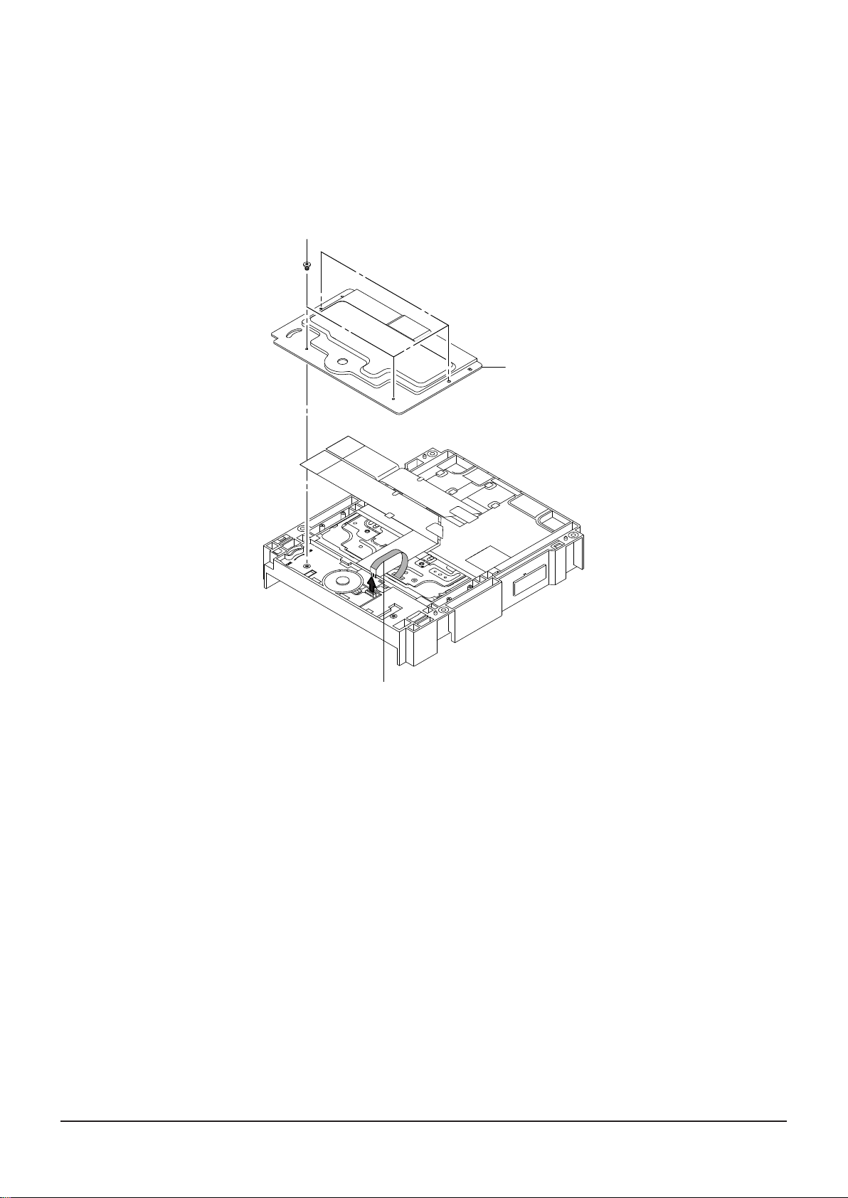
3-3-3 Cover Bottom Removal (Optional)
1) Remove 4 Screws q.
2) Li up the Cover Bottom w.
3) Remove FFC Cable e.
q 4 SCREWS
(M 1.7 X 5 W)
w COVER BOTTOM
e FFC CABLE
Fig. 3-9 Cover Bottom Removal (Optional)
 Loading...