

Samsung AW0801B, AW1001B, AW1201B, AW1801B Service Manual
ROOM AIR CONDITIONER
AW0801B AW1001B
AW1201B AW1801B
Manual
SERVICE
CONTENTSAIR CONDITIONER
11. Precautions
12. Product Specifications
13. Installation and Operating
Instructions
14. Disassembly and Reassembly
15. Troubleshooting
16. Exploded Views and Parts List
17. Block Diagram
18. PCB Diagram
19. Wiring Diagram
10. Schematic Diagram
1. Precautions
1. Precautions
1. Warning: Prior to repair, disconnect the
power cord from the circuit breaker.
2. Use proper parts: Use only exact
replacement parts. (Also, we recommend
replacing parts rather than repairing them.)
3. Use the proper tools: Use the proper tools
and test equipment, and know how to use
equipment may cause problems laterintermittent contact, for example.
4. Power Cord: Prior to repair, check the
power cord and replace it if necessary.
5. Avoid using an extension cord, and avoid
tapping into a power cord. This practice
may result in malfunction or fire.
6. After completing repairs and reassembly,
check the insulation resistance.
Procedure: Prior to applying power, measure
the resistance between the power cord and the
ground terminal. The resistance must be
greater than 30 megaohms.
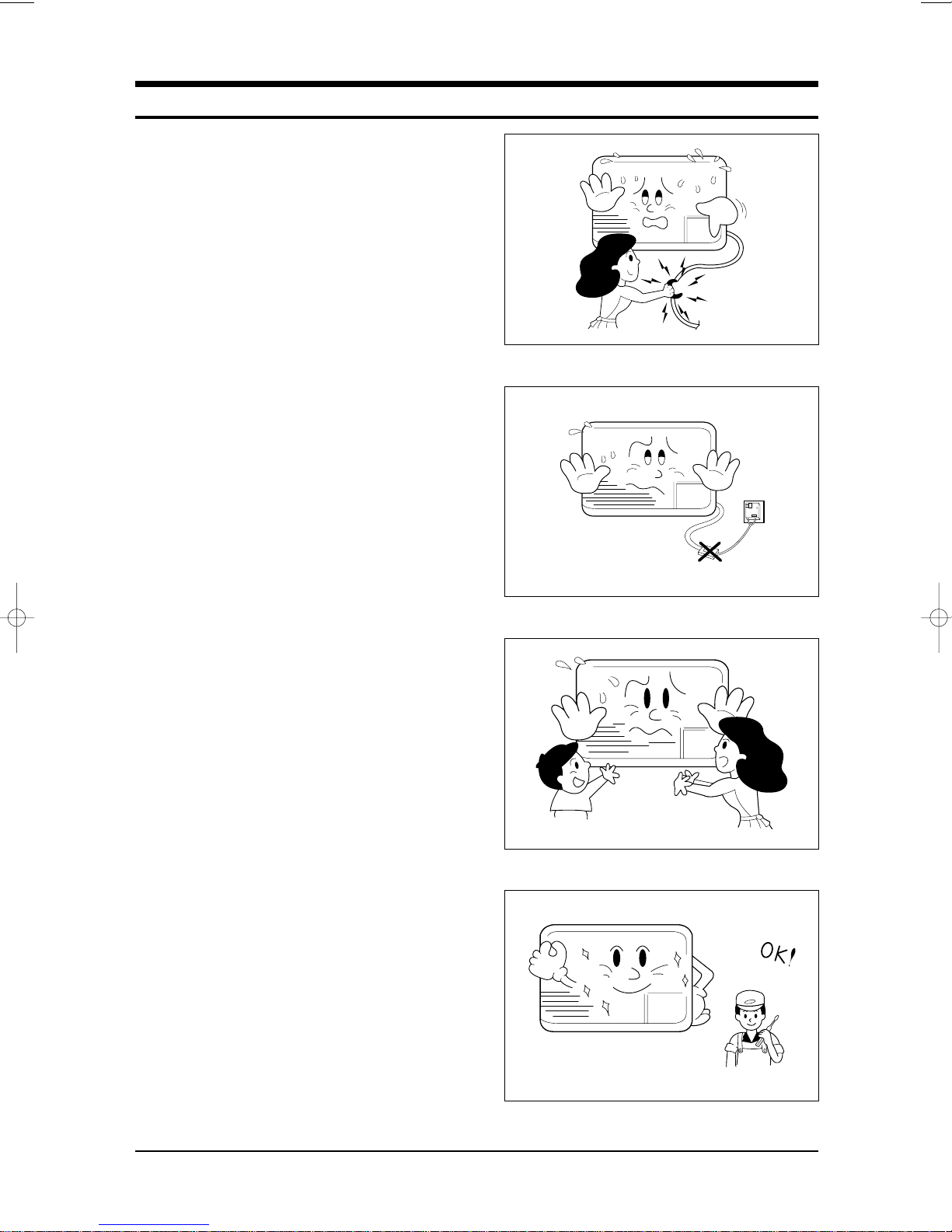
Fig. 1-1 Avoid Dangerous Contact
7. Make sure that the grounds are adequate.
8. Make sure that the installation conditions
are satisfactory.
Relocate the unit if necessary.
9. Keep children away from the unit while it is
being repaired.
10. Be sure to clean the unit and its surrounding
area.
Fig. 1-2 No Tapping and No Extension Cords
Fig. 1-3 No Kids Nearby!
Samsung Electronics 1-1
Fig. 1-4 Clean the Unit
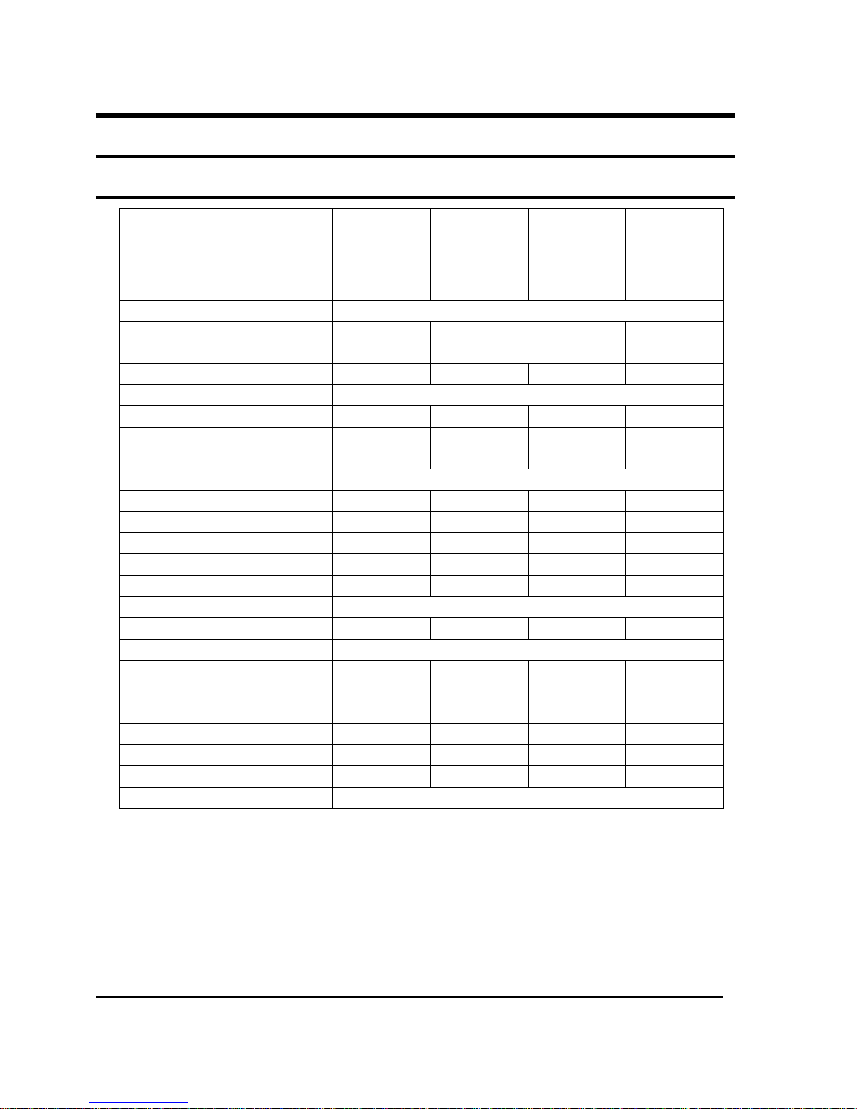
2.Product Specifications
2-1 Table
Item
Unit of
Measure
AW0801B AW1001B AW1201B AW1801B
Type
WINDOW
Dimension:
(Width×Height×Depth)
mm
520×345×485 600×394×595 660×425×730
Voltage
Volt 115 115 115 230-208
Phase
- SINGLE
Frequency
Hz 60 60 60 60
Operation Current
A 7.4 9.7 11.7 8.2/8.9
Power Consumption
W 820 1070 1270 1850/1800
Refrigerant Type
FREON R22
Refrigerant Change
g 390 480 1040 800
Capacity
BTU/h 8000 10500 12400 17900/17400
EER
BTU/h.W 9.8 9.8 9.8 9.7/9.7
Net Weight
Kg 29 43 43 63
Condenser
Row
2×15 2×17 2×17 3×19
Condenser Fan
Type Propeller Fan
Evaporator
Row
2×11 2 ×12 3×12 3×11
Evaporator Fan
Type Blower
Fan Motor
MODEL
YSLA-40-6-0001
YGN60-6B YGN60-6B YSK160-6A
Compressor(Rotary)
MODEL 44A080HU1EB 44B102HX1EF 44B124HX1EL 48D80IU1EH
Overload Protect
-
MRA12083-12008 MRA12109-12007 MRA98693-12007 MRA12046-12007
Compressor Capacitor
μF/VAC
35/370 40/370 50/370 35/450
Fan Motor Capacitor
μF/VAC
8/450 15/250 15/250 6/450
Fan Speed
RPM 1020/980/930 890/850/800 890/850/800 1050/1000/960
Thermo Control
- THERMISTOR
Samsung Electronics 2-1

MEMO
2-3 Samsung Electronics
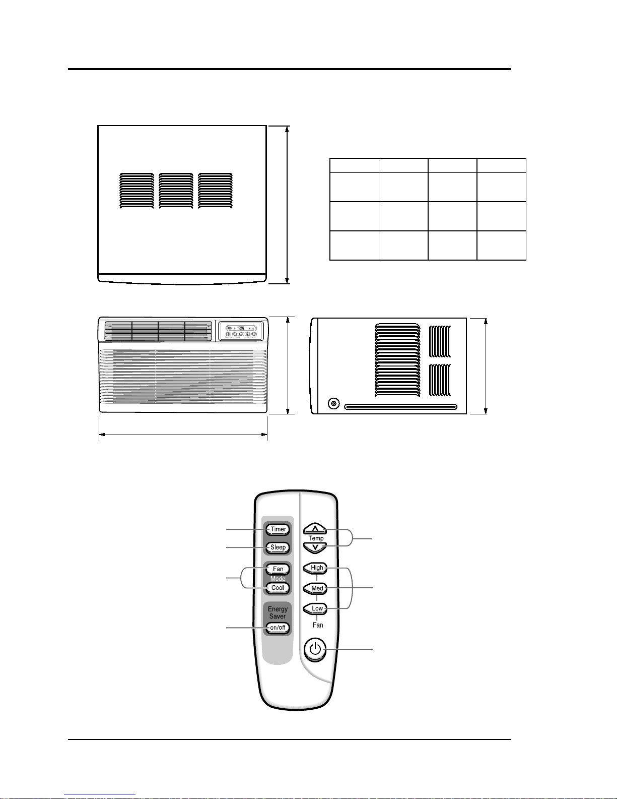
2-2 Dimensions
2-2-1 Main Unit
2-2-2 Remote Control
2-2 Dimensions
2-2-1 Main Unit
2-2-2 Remote Control
2-2 Dimensions
2-2-1 Main Unit
2-2-2 Remote Control
2-2 Dimensions
2-2-1 Main Unit
2-2-2 Remote Control
2-2 Dimensions
2-2-1 Main Unit
2-2-2 Remote Control
2-2 Dimensions
2-2-1 Main Unit
2-2-2 Remote Control
2-2 Dimensions
2-2-1 Main Unit
2-2-2 Remote Control
2-2 Dimensions
2-2-1 Main Unit
2-2-2 Remote Control
2-2 Dimensions
2-2-1 Main Unit
2-2-2 Remote Control
2-2 Dimensions
2-2-1 Main Unit
2-2-2 Remote Control
2-2 Dimensions
2-2-1 Main Unit
2-2-2 Remote Control
2-2 Dimensions
2-2-1 Main Unit
2-2-2 Remote Control
2-2 Dimensions
2-2-1 Main Unit
2-2-2 Remote Control
2-2 Dimensions
2-2-1 Main Unit
2-2-2 Remote Control
2-2 Dimensions
2-2-1 Main Unit
2-2-2 Remote Control
2-2 Dimensions
2-2-1 Main Unit
2-2-2 Remote Control
W
H
H
W
H
H
W
H
H
W
H
H
W
H
H
W
H
H
W
H
H
W
H
H
Front view
Side view
(Unit : mm)
2-4 Samsung Electronics
Front view
Side view
(Unit : mm)
2-4 Samsung Electronics
Front view
Side view
(Unit : mm)
2-4 Samsung Electronics
Front view
Side view
(Unit : mm)
2-4 Samsung Electronics
Front view
Side view
(Unit : mm)
2-4 Samsung Electronics
Front view
Side view
(Unit : mm)
2-4 Samsung Electronics
Front view
Side view
(Unit : mm)
2-4 Samsung Electronics
Front view
Side view
(Unit : mm)
2-4 Samsung Electronics
Front view
Side view
(Unit : mm)
2-4 Samsung Electronics
Front view
Side view
(Unit : mm)
2-4 Samsung Electronics
Front view
Side view
(Unit : mm)
2-4 Samsung Electronics
Front view
Side view
(Unit : mm)
2-4 Samsung Electronics
Front view
Side view
(Unit : mm)
2-4 Samsung Electronics
Front view
Side view
(Unit : mm)
2-4 Samsung Electronics
Front view
Side view
(Unit : mm)
2-4 Samsung Electronics
Front view
Side view
(Unit : mm)
2-4 Samsung Electronics
D
Temperature adjustment
buttons
Fan speed
adjustment buttons
On/Off button
Timer setting button
Sleep timer setting button
Mode selection
buttons
Energy Saver button
MODEL W H D
AW0801B 520 345 485
AW1001B
600 394 595
AW1201B
AW1801B 660 425 730
3. Installation and Operating Instructions
3-1 Installation
3-1-1 Selecting Area for Installation
1. Make sure that you install the unit in an area
providing good ventilation. The air conditioner
must not be blocked by any obstacle affecting the
air flow near the air inlet and air outlet.
2. Make sure that you install the unit in an area that
allow good air handling. The installation area
must be able to endure vibration from the unit.
3. Make sure that you install the unit away from
heat or vapor.
4. Make sure that you install the unit in an area
which is cool and has adequate space.
5. Make sure that you install the unit in an area
away from TVs, audio units, cordless phones,
fluorescent lighting fixtures and other electrical
appliances (obtain a clearance of at least one
meter).
6. Make sure that you install the unit in an area
which provides easy drainage for condensed
water.
7. Make sure that you install the unit in an area not
exposed to rain or direct sunlight.
(Install a separate sunblind if exposed to direct
sunlight.)
8. Make sure that you install the unit in an area
allowing good air movement. Do not install it in
a space that would cause noise amplification of
noise.
9. Fix the unit firmly if mounted in a high place.
Caution:
Do not use the air conditioner in the following environments : greasy areas (including areas near
machines), or marine areas. Contact your local dealer for advice.
Samsung Electronics 3-1
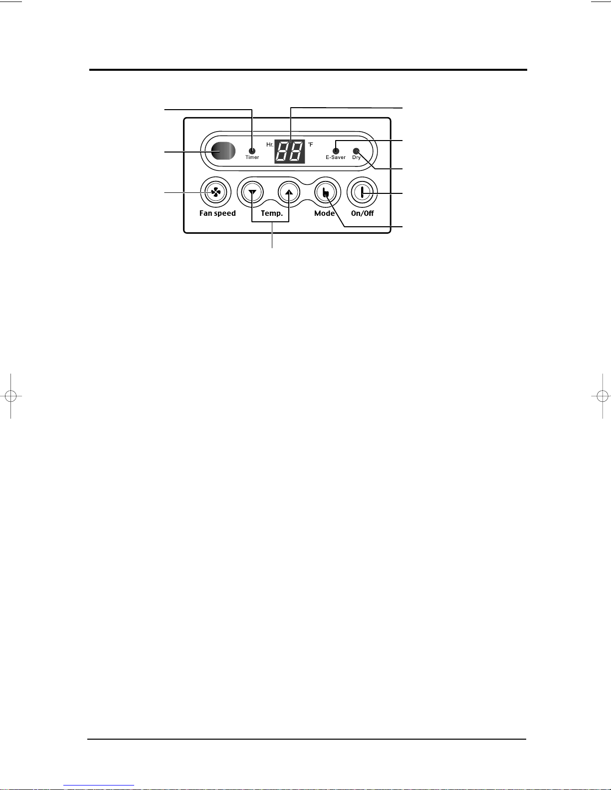
3-2 Function Description
Temperature/Timer
settings
Energy Saver indicator
Dry adjustment indicator
Fan speed
adjustment button
Timer indicator
Mode selection button
(Cool, Fan, Dry)
T emperature
adjustment buttons
On/Off button
Remote control
sensor
3-2-1 Cooling operation mode
The compressor is turned on and off according to the ambient temperature and set temperature.
1) Compressor on and off control
• Compressor on and off control according to the ambient temperature
The compressor is turned off when "ambient temperature = set temperature
*
The compressor is turned on when "ambient temperature = set temperature +1˚C"
*
2) Default value after power reset ➔ set temperature = 75˚F
Fan speed = High
3) Set temperature indicating (setting) range : 1˚F interval from 64˚F to 86˚F.
3-2-2 Fan operation mode
1) If "Fan operation mode" signal is received from remocon or panel.
➔ the compressor is immediately turned off and only fan motor is operated at set blowing speed.
➔ it changes such as "High ➔ Med ➔ Low ➔ High"( if Fan speed is selected).
2) The initial Fan motor speed is set to "High".
3) The set temperature can not be indicated and set.
3-2-3 Energy saver operation mode
If the compressor turn off at the cooling operation, the fan motor turn off after operation during the fixation
*
time only, and operation that energy saver by turn off the fixation time only, and operation that energy saver
by turn off the motor continuously before the condition of the compressor on.
The fan motor is not operated at flow wind operation.
*
Energy saver operation specification at the cooling operation.
*
1) Fan motor control in compressor on : operate with setting wind speed
2) Fan motor control in compressor off : After compressor off, the fan motor is operated breeze for 2 minutes
and then it turn off.
3) After the fan motor off, the compressor and fan motor is operated normally when the compressor on.
3-2 Samsung Electronics
Installation and Operating Instructions
3-2-4 Sleep operation mode
1) Enable to sleep operation only when cooling operation.
2) First, 7-SEG LED DISPLAY "SLEEP" while 15 second, Second, 7-SEG LED DISPLAY "8Hr"
And, automatically SET OFF after operated while 8 Hour
3) If sleep operation, setting Temperature rise 1˚C after 1 Hour
4) ON TIMER operation, not operation, ENERGY SAVER operation, not sleep operation.
3-2-5 Dry operation mode
If the atmosphere in the room is very humid or damp,use this operation mode. It can remove excess humidity
without lowering the room temperature too much.
) The quantity of air is adjusted automatically.
1
3-2-6 LED display indication in case of error detection
ERROR OPERATION
ROOM THERMISTOR
(OPEN or SHORT)
1) Set operation in case of error occurrence.
• Malfunction of each temperature sensor (open, short)
- Error mode display, warning sound.
- The operation status is off.
7-SEG
LED DISPLAY
E1 displayed
Samsung Electronics 3-3

MEMO
3-4 Samsung Electronics
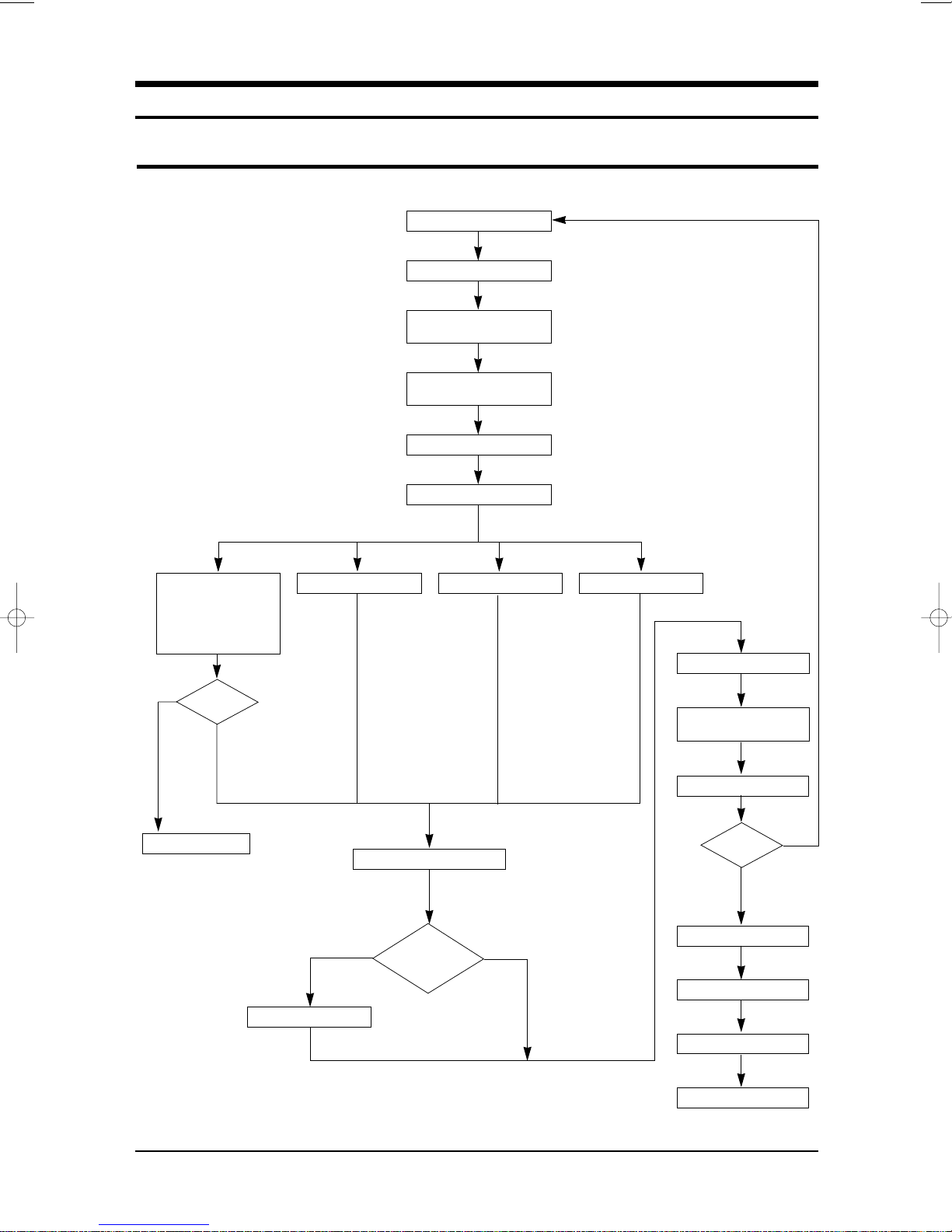
4. Disassembly and Reassembly
4-1 Compressor Replacement Flow Chart
Locate cause of defect
Release refrigerant
Disconnect electrical wiring
from compressor
Cut refrigerant lines
from compressor
Plug disconnected lines
Replace compressor
Inspect electrical
wiring for defects,
and terminals for
correct and secure
connections
Y
Problem?
N
Corrective action
Solder discharge line
Y
Add oil as necessary
Solder suction line Use nitrogen gas
Check refrigerant oil level
Low oil level?
Perform soldering function
Fill system with
nitrogen gas
Check for leakage
Leakage?
Y
N
N
Release nitrogen gas?
Evacuate system
Samsung Electronics 4-1
Recharge system
Pinch and braze filling tube
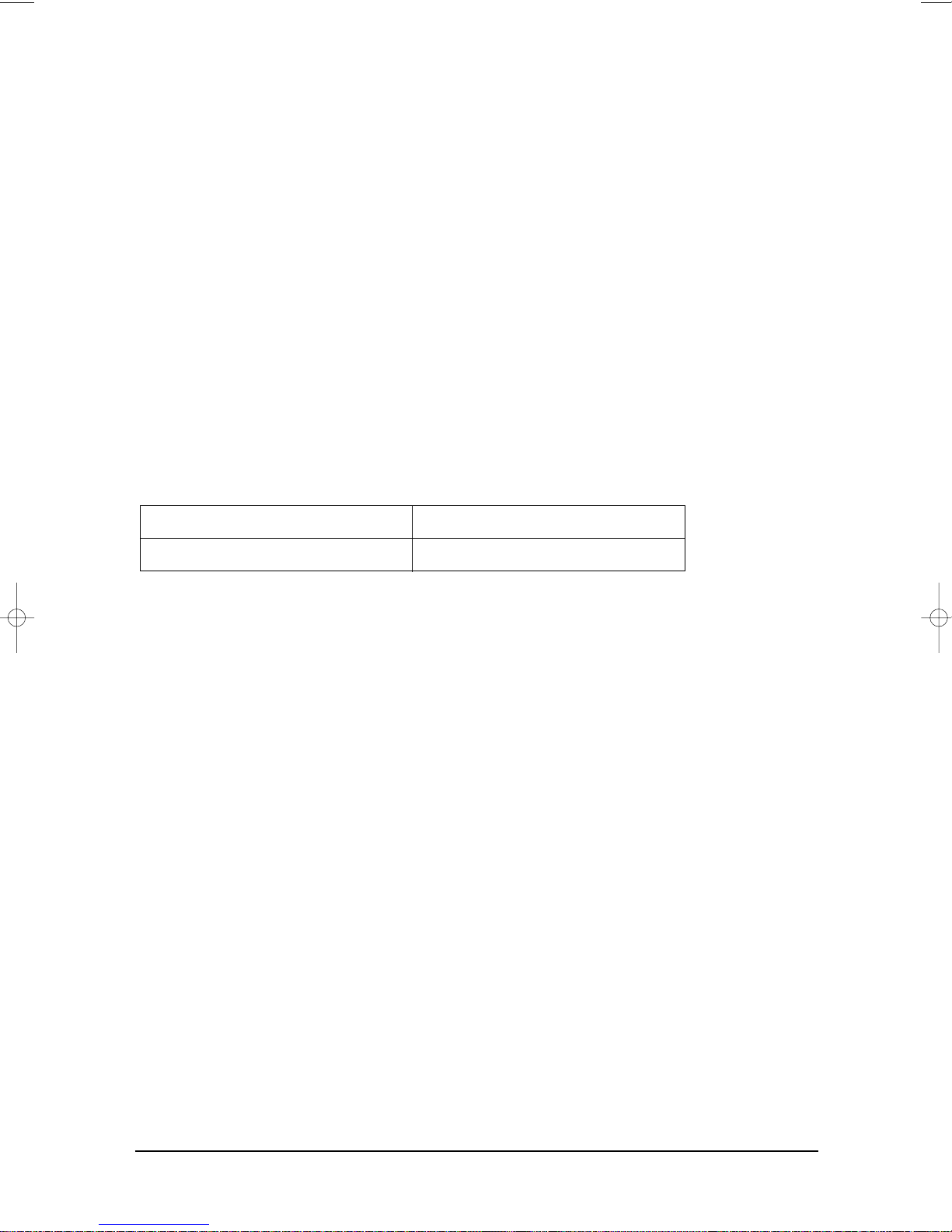
4-2 Checking the oil
Fill the transparent container with 10cc of oil, and then conduct the test.
4-2-1 Oil quality
Condition of
Refrigerant Cycle
Normal
Over-heated
Compressor Damage
Color
Straw Yellow
Brown Color
Dark Brown
Oil Condition
Odor
No Odor
Pungent oil
4-2-2 Replacing and refilling the refrigerant oil
1. Change the compressor - DO NOT recharge the oil as the compressor itself is
already charged.
2. Change the condenser .... add 50cc
3. Change the evaporator .... add 50cc
4. When the refrigerant is replaced .... add 30cc oil.
5. After vacuum is completed, the oil is filled through the high pressure side.
6. In the event of a refrigerant leak, generally it is not necessary to add oil.
(Unless the oil has leaked significantly.)
Remarks
Return with the system
-
Change the oil
Change the oil
4-2 Samsung Electronics
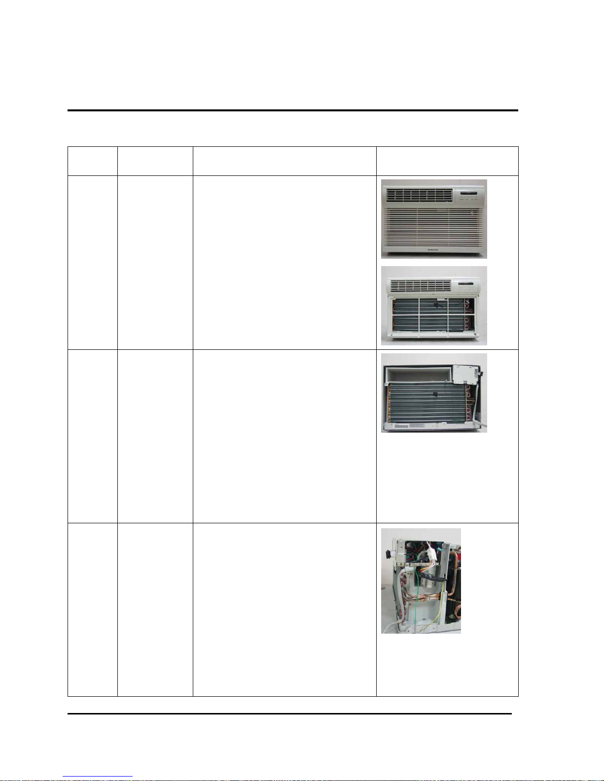
4-3.Disassembly and Reassembly Procedure(AW1001B/AW1201B/AW1801B)
Stop operating the air conditioner, and pull out the power cord before repair.
No. Part Name Procedures Remarks
1 Ass’y Grille
1.Pull the Grille air inlet and Guard air filter out.
2.Remove the screw on the panel front.
3.Hold the lower part of panel with two hands
while pressing down on both sides of the lower
part of the cabinet, pull it forward by about
30mm,and then lift it up carefully for
removal.(Must un-connect the Displayer with
the controller inside.)
2 Ass’y Cabinet
1.Remove 2 screws on the both side of the
cabinet.
2.Pull the front part both side, and remove the
unit from the cabinet.
3 Ass’y Control
1.Remove the earth screw fixed on the cabinet.
2.Remove 3 screws fixed on the partition and
frame up.
3.Remove the screw fixed for the power cord.
4.Un-connect the motor wire and comp lead
wire, then take out the control box upward.
Samsung Electronics 4-3
 Loading...