

Samsung AS12HPCN, AP09HPC, AS09HPD, AS12HPC, AS12HPD Service Manual
...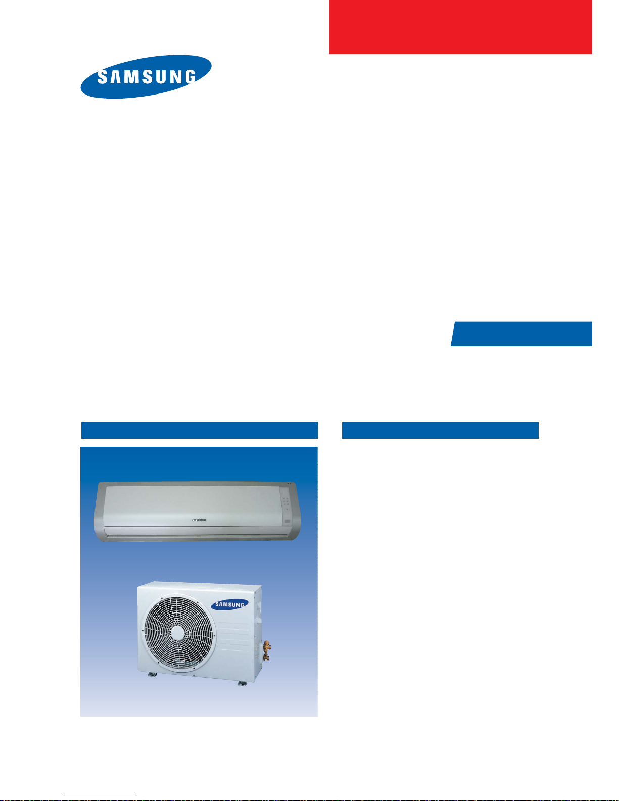
THE FEATURE OF PRODUCTAIR CONDITIONER
■
Energy Saving Function
■
High Impressive & Elegant Design
■
Excellent Dust Collection Filter
: The metallic dust filter is used.
■
Multi Functional Cleaning System
: The anti allergy filter and activated deodorizing
filter are adopted.
■
Human Touch Remote control
SER VICE
Manual
For more information, Please access to our service web site (http://itself.sec.samsung.co.kr)
Basic
: AS12HPCN
Model
:
AS12HM3
Model
:
Model Code :
Model Code :
Model Code :
SPLIT-TYPE AIRCONDITIONER
AS09HPCN/AS12HPCN/AS09HPDN/AS12HPDN
AS09HPCX/AS12HPCX/AS09HPDX/AS12HPDX

Contents
11. Precautions
1-1 Installing the air conditioner
1-2 Power supply and circuit breaker
1-3 During operation
1-4 Disposing of the unit
1-5 Others
12. Product Specifications
2-1 The Feature of Product
2-2 Name of Each Part
2-3 Product Specifications
...........................................................................................................................................
..........................................................................................................
...............................................................................................
................................................................................................................................
........................................................................................................................
....................................................................................................................................................
..............................................................................................................
..................................................................................................................
...........................................................................................................................
....................................................................................................................
2-4 The Comparative Specifications of Product
2-5 Accessory and Option Specifications
13. Alignment and Adjustments
3-1 Error mode and check method
3-2 Setting Option Setup Method
14. Disassembly and Reassembly
Indoor Unit
4-1
4-2 Outdoor Unit
...........................................................................................................................................
........................................................................................................................................
.................................................................................................
...................................................................................................
......................................................................................................
...........................................................................................
..........................................................................
.......................................................................................
1-1
1-1
1-1
1-1
1-2
1-2
2-1
2-1
2-2
2-4
2-5
2-7
3-1
3-1
3-5
4-1
4-1
4-5
15. Exploded Views and Parts List
5-1 Indoor Unit
5-2 Outdoor Unit
5-3 Ass'y Control In
16. Electrical Parts List
17. Wiring Diagram
18. Schematic Diagram
19. Circuit Descriptions
9-1 PCB Circuit Descriptions
9-2 Refrigerating Cycle Diagram
...........................................................................................................................................
.........................................................................................................................................
...................................................................................................................................
.......................................................................................................................
..................................................................................................................................
.......................................................................................................................
.....................................................................................................................
.................................................................................................................
.........................................................................................................
.........................................................................................
5-1
5-1
5-7
5-9
6-1
7-1
8-1
9-1
9-1
9-2

Contents
10. PCB Diagram
11. Operating Instruction and Installation
11-1 Main Function
.......................................................................................................................................
........................................................................
....................................................................................................................................
11-2 Wireless Remote Control-Buttons and Display
12. Troubleshooting
12-1 Items to be checked first
12-2 Fault Diagnosis by Symptom
12-3 PCB Inspection Method
12-4 Main Part Inspection Method
13. Block Diagram
14. Reference Sheet
14-1 Index for Model Name
14-2 Refrigerant Pressure during the Charging
14-3 Pressure & Capacity mark
14-4 Q & A for Non-trouble
14-5 Cleaning/Filter Change
14-6 Installation
...............................................................................................................................
..............................................................................................................
......................................................................................................
................................................................................................................
......................................................................................................
....................................................................................................................................
...............................................................................................................................
...................................................................................................................
............................................................................
...........................................................................................................
.....................................................................................................................
..................................................................................................................
...........................................................................................................................................
14-7 Installation Diagram of Indoor Unit and Outdoor Unit
10-1
11-1
...................................................................
12-1
13-1
14-1
......................................................
11- 1
11- 4
12-1
12-2
12-6
12-8
14-1
14-2
14-2
14-3
14-6
14-8
14-9
1. Precautions
1-1 Installing the air conditioner
● Users should not install the air conditioner by themselves.
Ask the dealer or authorized company to install the air conditioner except the window-type air conditioner in U.S.A and Canada.
● If you don’t install the air conditioner properly, it may cause a fire, a water leakage or an electric shock.
● You must install the air conditioner according to the national wiring regulations and safety regulations.
● Install the indoor unit higher than 2.5m from the floor to avoid the injury caused by the operation of the fan.
(except the window-type air conditioner)
● The manufacturer is not responsible for any accidents or injury caused by an incorrect installation.
● When installing the built-in type air conditioner, keep all electric cables such as the power cable and the connection cord in pipes,
ducts, or cable channels to protect them from the danger of impact or any other incidents.
1-2 Power supply and circuit breaker
● If the power cord of the air conditioner is damaged, it must be replaced by the manufacturer or a qualified person in order to
avoid a hazard.
● The air conditioner must be plugged into an independent circuit if applicable or connect the power cable to the auxiliary circuit
breaker.
An all pole disconnection from the power supply must be incorporated in the fixed wiring with a contact opening of >3mm.
● Do not extend an electric cord to the air conditioner.
● The air conditioner must be plugged in after you complete the installation.
1-3 During operation
● Do not repair the air conditioner at your discretion.
It is recommended to contact a service center directly.
● Never spill any kind of liquid on the air conditioner.
If this happens, turn off the air conditioner and contact an authorized service center.
● Do not insert anything between the airflow blades to prevent damage of the inner fan and consequent injury.
Keep children away from the air conditioner.
● Do not place any obstacles in front of the air conditioner.
● Do not spray any kind of liquid into the indoor unit. If this happens, turn off the air conditioner and contact a service center.
● Make sure that the air conditioner is well ventilated at all times:
Do not place a cloth or other materials over it.
● Remove the batteries if you don’t use the remote control for a long time. (If applicable)
● Use the remote control within 7 meters from the indoor unit. (If applicable)
1-1Samsung Electronics
1-4 Disposing of the unit
● Before throwing out the air conditioner, remove the batteries from the remote control.
● When you dispose of the air conditioner, consult your dealer. If pipes are removed incorrectly, refrigerant may blow out and
cause air pollution. When it contacts with your skin, it can cause skin injury.
● The package of the air conditioner should be recycled or disposed of properly for environmental reasons.
1-5 Others
● Never store or load the air conditioner upside down or sideways to prevent the damage to the compressor.
● Young children or infirm persons should be always supervised when they use the air conditioner.
● Max current is measured according to IEC standard for safety.
● Current is measured according to ISO standard for energy efficiency.
Samsung Electronics1-2

2. Product Specifications
2-1 The Feature of Product
■ Energy saving function
Makes a room cool with and energy saving and arises the efficiency of air conditioner.
■ High impressive & elegant design
With a Smart and fashionable style, the high impressive interior design allow this product to set place in anywhere.
■ Excellent dust collection filter
With a metallic dust filter that upgrades the dust collection function than a common plastic filter, you can enjoy the best
cleanliness.
■ Multi functional cleaning system
With an anti-allergy filter and activated deodorizing filter, it removes an allergy antigen as well as a tobacco odor.
■ Human touch remote control
The use of air conditioner is easier and more convenient by the human touch remote control of new design.
2-1Samsung Electronics

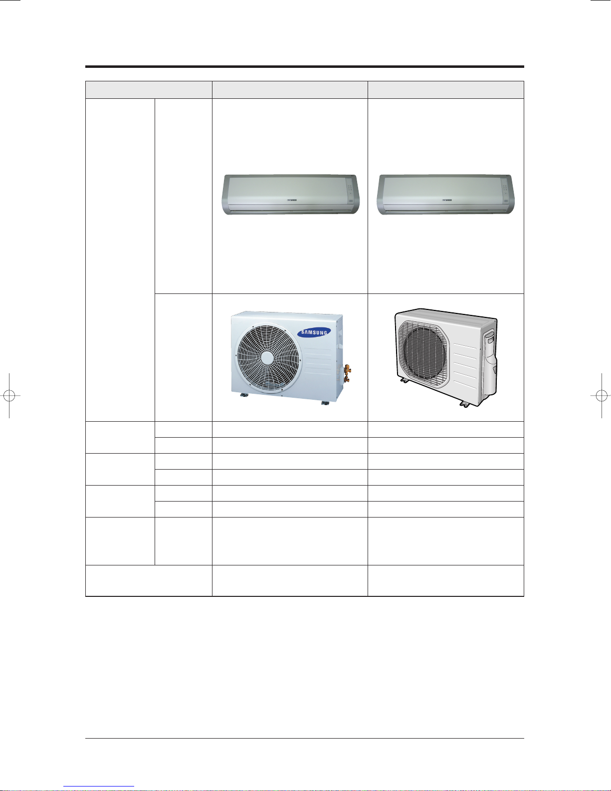
2-2 Name of Each Part
2-2-1 Indoor Unit
The design and shape can be changed according to the model.
Air Inlet
Room Temperature sensor
Power(On/ Off) button
Air filter
(under the grille)
(Auto-Cool, Cool, Dry, Fan : Blue
Air flow blades
(outlet)
Set temperature &
room temperature
Operation indicator
Auto-Heat, Heat : Orange)
Turbo function indicator
Timer indicator
Fan speed indicator
Remote control sensor
(Blue)
(Orange)
(Blue)
Auto cleaning indicator
(Blue)
Energy saving indicator
(Blue)
Anions indicator
(Blue)
Note : • In the Auto mode, 2 fan indicators increase and decrease continuously and turn round.
• In the modes except the Auto mode, the fan speed indicator increases and decreases
continuously and turn round each time you press the button. If you set the Turbo
function, the fan speed indicator turns round with the maximum setting and speed.
• If you want to turn on/off the Display during operation, press the button on
the remote control.
• The room temperature sensor senses air temperature around the
sensor, and shows the temperature on the display.
Samsung Electronics2-2

2-2-2 Outdoor Unit
Product Specifications
Air Inlet(Rear)
Air Outlet
Connection Valve
2-3Samsung Electronics
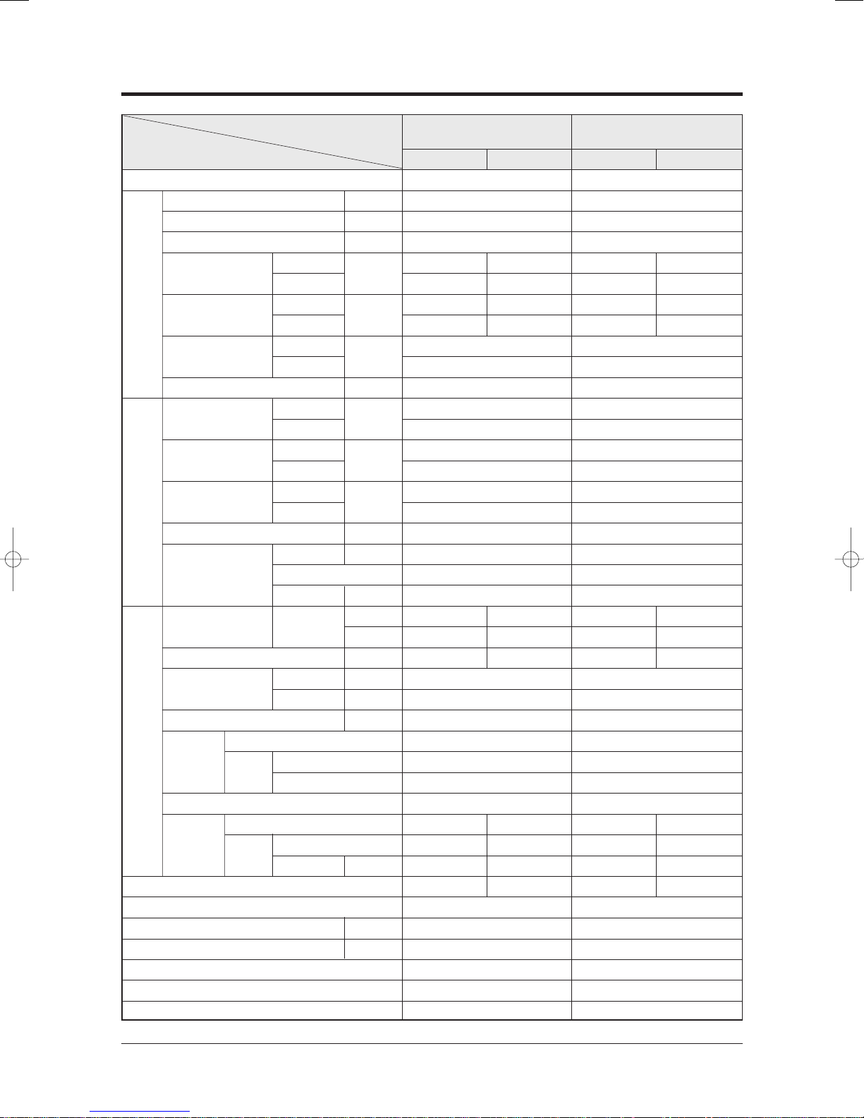
2-3 Product Specifications
Item
Type
Cooling kW
Heating kW
Dehumidifying |/h
Air Volume
Performance
Noise
Energy Efficiency Ratio
Power ph-V-Hz
Power Consumption
Operating Current
Power Factor
Power
Starting Current A
Power Cord Number of Core Wire
Outer Dimension
Weight(Net) kg
Refrigerant Pipe
Drain Hose DxL(mm)
Size
Compressor Motor Type
Oil Type
Blower Motor Type
Heat Exchanger
Refrigerant Control Unit
Freezer Oil Capacity cc
Refrigerant to Change(R410A) g
Protection Device(OLP)
Cooling Test Condition
Maximum Operation Condition
Type
Type
Cooling
Heating
Cooling
Heating
Cooling
Heating
Cooling
Heating
Cooling
Heating
Cooling
Heating
Length m
Capacity A
WidthxHeight
xDepth
Liquid mmxL(m)
Gas mmxL(m)
Rated Output
Rated Output W
(H/M/L)
Model
3
m
/min
dB
(H/L)
W/W
W
A
%
mm
inch
AP09HPC
AS09HPD
Indoor unit Outdoor unit
Wall-mounted
2.70
2.90
1.0
7.5/6.9/6.3 25
8.0/7.4/6.8 25
40/30 51
40/30 51
3.21
3.41
1-220/240-50
840
850
3.7
3.7
97.3
97.3
21
2.1
5G
250V-10A
950x268x165 720x530x260
x
37.4x10.6
2ROW 12STEP 1ROW 24STEP
INDOOR UNIT : DB27˚C WB19˚C OUTDOOR UNIT : DB35˚C WB24˚C
INDOOR UNIT : DB32˚C WB23˚C OUTDOOR UNIT : DB43˚C WB26˚C
6.5 28.3x20.9x10.2
9.0 31.0
ø6.35
x
5
ø9.52x5
ø18
x
550
Rotary, G4A091JU1EP
Induction Motor(PSC)
930
DAPHNE FV685(PVE)
Cross-flow Propeller
Resin/steel steel
15 50
CAPILLARY TUBE
280
580
RBC12054-12500
950x268x165 720x530x260
37.4x10.6x6.5 28.3x20.9x10.2
2ROW 12STEP 2ROW 24STEP
AS12HPC
AS12HPD
Indoor unit Outdoor unit
Wall-mounted
3.50
3.80
1.4
8.3/7.0/5.7 25
9.5/8.9/8.3 25
43/31 53
43/31 53
3.21
3.22
1-220/240-50
1,090
1,180
5.0
5.3
98.7
96.8
28
2.1
5G
250V-10A
9.5 33.0
ø6.35x5
ø12.70x5
ø18x550
Rotary, G4B124JU2EL
Induction Motor(PSC)
1,267
DAPHNE FV685(PVE)
Cross-flow Propeller
Resin/steel steel
15 50
CAPILLARY TUBE
500
900
RBC12127-12500
Samsung Electronics2-4
2-4 The Comparative Specifications of Product
Design
Item
AS09HPC/AS09HPD AS09HPB
Indoor
Unit
Outdoor
Unit
Net Weight
Outer Dimension
Noise
Air Purifying System Filter
Indoor Display
Indoor Unit
Outdoor Unit
Indoor Unit
Outdoor Unit
Indoor Unit
Outdoor Unit
9.0kg
31.0kg
950x268x165mm
720x530x260mm
40dB↓
51dB↓
Silver Nano Metallic Filter
Anti-Allergy Filter
Deodorizing Filter
Detachable Display
Rotation Blue LED Display
9.0kg
33.8kg
950x268x165mm
790x548x285mm
40dB↓
51dB↓
Silver Nano Metallic Filter
Anti-Allergy Filter
Deodorizing Filter
Detachable Display
Rotation Blue LED Display
2-5Samsung Electronics

Product Specifications
Design
Item
AS12HPC/AS12HPD AS12HPB
Indoor
Unit
Outdoor
Unit
Net Weight
Outdoor Unit
Indoor Unit
Indoor Unit
Outer Dimension
Outdoor Unit
Indoor Unit
Noise
Outdoor Unit
Air Purifying System Filter
Indoor Display
9.0kg
33.0kg
950x268x165mm
720x530x260mm
43dB↓
53dB↓
Silver Nano Metallic Filter
Anti-Allergy Filter
Deodorizing Filter
Detachable Display
Rotation Blue LED Display
9.0kg
36.0kg
950x268x165mm
790x548x285mm
43dB↓
53dB↓
Silver Nano Metallic Filter
Anti-Allergy Filter
Deodorizing Filter
Detachable Display
Rotation Blue LED Display
Samsung Electronics2-6

2-5 Accessory and Option Specifications
O
W
N
E
R
'
S
I
N
S
T
R
U
C
T
I
O
N
S
M
A
N
U
A
L
D
E
I
N
S
T
R
U
C
C
I
O
N
E
S
I
S
T
R
U
Z
I
O
N
I
P
E
R
L
'
U
S
O
M
A
N
U
A
L
D
E
I
N
S
T
R
U
Ç
Õ
E
S
M
A
N
U
E
L
D
'
U
T
I
L
I
S
A
T
I
O
N
G
E
B
R
A
U
C
H
S
A
N
W
E
I
S
U
N
G
S
p
l
u
t
-
t
y
p
e
R
o
o
m
A
i
r
C
o
n
d
i
t
i
o
n
e
r
A
i
r
e
a
c
o
n
d
i
c
i
o
n
a
d
o
d
o
m
é
s
t
i
c
o
s
i
s
t
e
m
a
S
p
l
i
t
C
o
n
d
i
z
i
o
n
a
t
o
r
e
d
'
a
r
i
a
p
e
r
a
m
b
i
e
n
t
i
a
d
u
n
i
t
à
S
e
p
a
r
a
t
e
A
p
a
r
e
l
h
o
d
e
a
r
c
o
n
d
i
c
i
o
n
a
d
o
t
i
p
o
S
p
l
i
t
C
l
i
m
a
t
i
s
e
u
r
d
e
t
y
p
e
s
é
p
a
r
é
G
e
t
e
i
l
t
e
r
a
u
m
k
l
i
m
a
a
n
l
a
g
e
O
W
N
E
R
'
S
I
N
S
T
R
U
C
T
I
O
N
S
M
A
N
U
A
L
D
E
I
N
S
T
R
U
C
C
I
O
N
E
S
I
S
T
R
U
Z
I
O
N
I
P
E
R
L
'
U
S
O
M
A
N
U
A
L
D
E
I
N
S
T
R
U
Ç
Õ
E
S
M
A
N
U
E
L
D
'
U
T
I
L
I
S
A
T
I
O
N
G
E
B
R
A
U
C
H
S
A
N
W
E
I
S
U
N
G
S
p
l
u
t
-
t
y
p
e
R
o
o
m
A
i
r
C
o
n
d
i
t
i
o
n
e
r
A
i
r
e
a
c
o
n
d
i
c
i
o
n
a
d
o
d
o
m
é
s
t
i
c
o
s
i
s
t
e
m
a
S
p
l
i
t
C
o
n
d
i
z
i
o
n
a
t
o
r
e
d
'
a
r
i
a
p
e
r
a
m
b
i
e
n
t
i
a
d
u
n
i
t
à
S
e
p
a
r
a
t
e
A
p
a
r
e
l
h
o
d
e
a
r
c
o
n
d
i
c
i
o
n
a
d
o
t
i
p
o
S
p
l
i
t
C
l
i
m
a
t
i
s
e
u
r
d
e
t
y
p
e
s
é
p
a
r
é
G
e
t
e
i
l
t
e
r
a
u
m
k
l
i
m
a
a
n
l
a
g
e
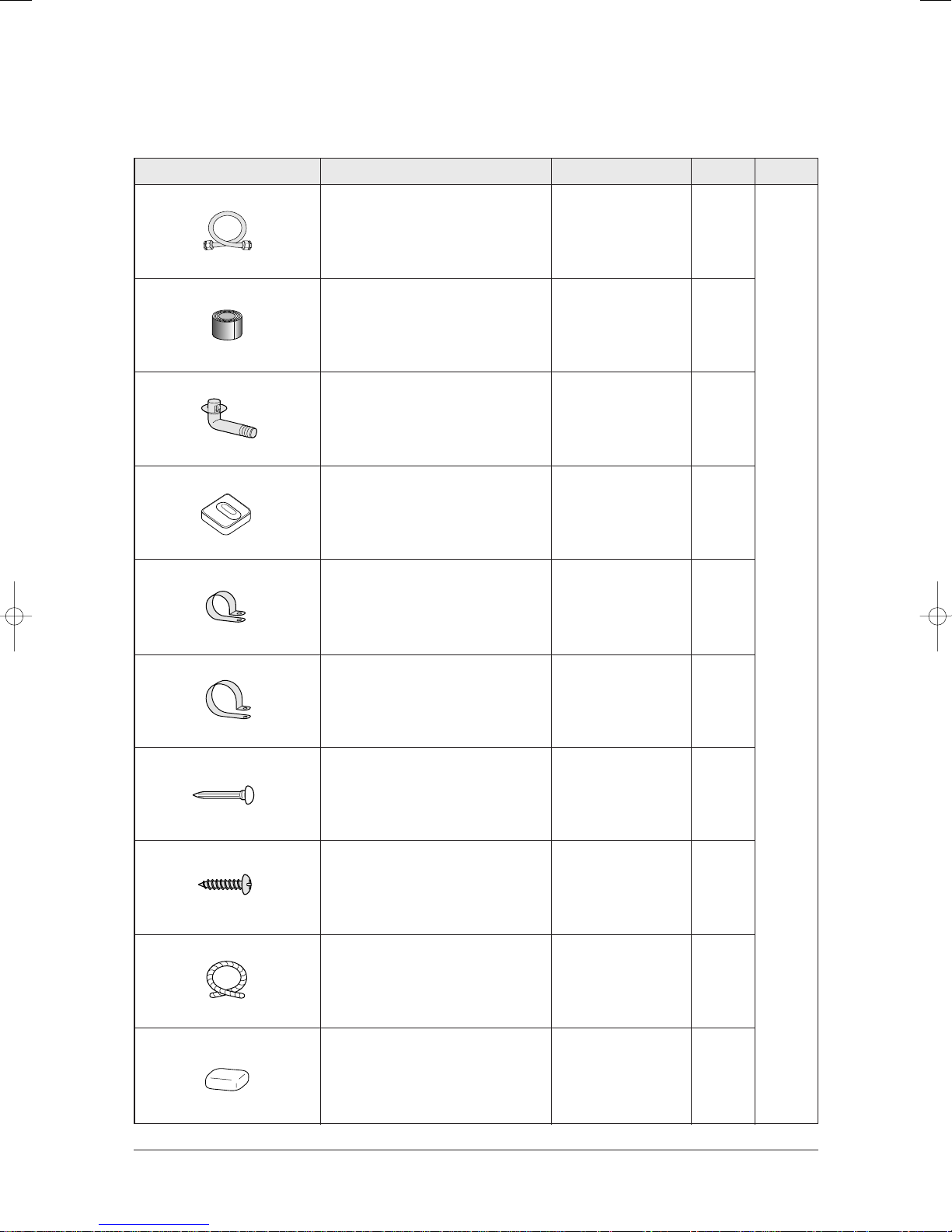
2-5-1 Accessories
Item Descriptions Q'TYCode-No. Remark
Installation Plate DB70-00514A 1
Remote Control DB93-03016R 1
Batteries for Remote Control DB47-90024A 2
User's Manual DB98-24445A 1
Installation Manual DB98-24444A 1
5-wire Assembly Cable - 1
Drain Plug DB67-20011A 1
Indoor
Unit
Outdoor
Unit
Rubber Leg DB73-00179A 4
Assembly Pipe, ø6.35mm DB96-10453B 1
Accessory
Box
Assembly Pipe, ø12.70mm(✳✳12✳✳) DB62-70003E 1
2-7Samsung Electronics
Product Specifications
Accessories(cont.)
Item Descriptions Q'TYCode-No. Remark
Assembly Pipe, ø9.52mm(✳✳09✳✳) DB96-04578G 1
Vinyl Tape, Width 50mm DB72-00459A 1
Drain Plug DB67-20011A 1
Rubber Leg DB73-00179A 4
Pipe Clamps A DB39-20224A 3
Pipe Clamps B DB39-20224B 3
Cement Nail - 6
M4x16 Tapping Screws 6002-000215 6
Drain Hose, length 2m DB62-00487A 1
Accessory
Box
Putty 100g DB98-10568A 1
Samsung Electronics2-8
3. Alignment and Adjustments
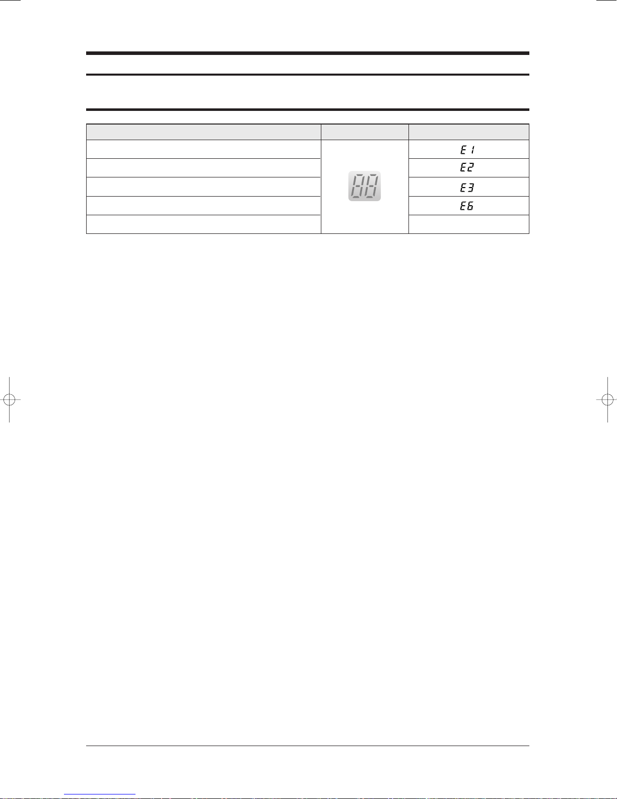
3-1 Error mode and check method
Error Mode
Indoor unit room temperature sensor error (open or short)
Indoor unit heat exchanger temperature sensor error (open or short)
Indoor fan motor malfunction
EEPROM error
Option error (option wasn't set up or option data error) Display Flickering
LAMP 7-segment Display
3-1Samsung Electronics

Alignment and Adjustments
3-1-1 Room temperature sensor Error
Error Mode
Indoor unit room temperature sensor error(open or short)
Detach the assembly sensor from the
ASS'Y PCB CN43 connector and measure
the sensor resistance with an ohmmeter (tester)
between Pin #1 and #2.
Is the sensor resistance value
10KΩ ±3% at the room temperature
of 25˚C?
Yes
Connect the sensor to CN43,
supply power, and measure the voltage of
#1 and #2 of the CN43 connector.
No
LAMP 7-segment Display
ASS'Y Sensor Replace
SENSOR Resistance Value : 20˚C-12.09kΩ
SENSOR Resistance Value : 30˚C-8.31kΩ
SENSOR Resistance Value : 35˚C-6.94kΩ
SENSOR Resistance Value : 40˚C-5.83kΩ
Below 0.5V?
No
Over 4.9V?
No
MICOM Error or Connector(CN43) check
Yes
Yes
Poor ASS'Y PCB Replace
Poor ASS'Y PCB Replace
Samsung Electronics3-2

3-1-2 Room Pipe sensor Error
Alignment and Adjustments
Error Mode
Indoor unit heat exchanger temperature sensor error
(open or short)
LAMP 7-segment Display
1. Check the assembly condition of the sensor connector(CN43) on the indoor unit Main PCB and if not assembled, reassemble
the connector accurately.
2. Detach the room pipe sensor connector(CN43) and check the resistance between Pin #3 and #4.
Temperature(˚C)
15
20
25
Resistance Value(Kohm)
14.68
12.09
10
Temperature(˚C)
30
35
40
Resistance Value(Kohm)
8.31
6.94
5.83
Others
The data tolerance
is ±3%.
If the above data is not met, replace the room pipe sensor.
3. Assemble the room pipe sensor to PCB, plug in, and check the voltage of connector 3 and 4. If the resistance is below 0.5V
or over 4.9V, replace the indoor Main PCB. (short or disconnected in the PCB board)
3-3Samsung Electronics
Alignment and Adjustments
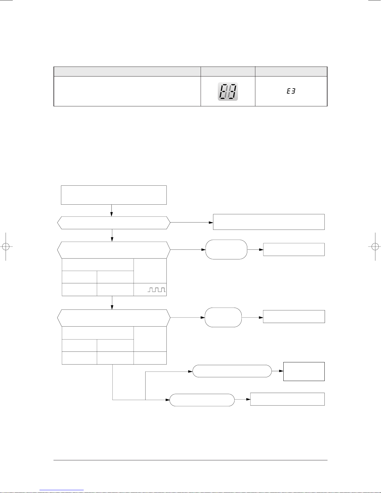
3-1-3 Indoor Unit Fan Motor Error
Error Mode
LAMP 7-segment Display
Indoor Unit Fan Motor Malfunction
1. Checklist :
1) Is the indoor unit fan motor properly connected with the connector (CN72)?
2) Is the AC voltage correct?
3) Is HALL IC in indoor fan motor properly connected with the connector (CN44)?
4) Is the running capacitor (CR71) properly connected with PCB board?
2. Troubleshooting procedure
After unplugging out the power cord should
be reconnected within 5 seconds.
Yes
No
No
Micom is
out of order.
Does the OPERATION lamp blink?
Yes
Does the Solid State Relay(SS71) work properly?
Check as in the procedure "No power".
Micom should be replaced
Test rod location
+-
SS71-SS71-
Yes
Is the supply voltage of the fan motor sufficient?
Test rod location
PCB CN72
pin #3 and #5 Fan operating
Condition
Yes
Normal
Voltage
12V
Normal
voltage
About AC180V
No
Fan motor is out of order.
PCB is
out of order.
Motor Fan-Capacitor is out of order
PCB should be replaced.
Replace Motor
Fan-Capacitor
Fan motor should be replaced.
Samsung Electronics3-4

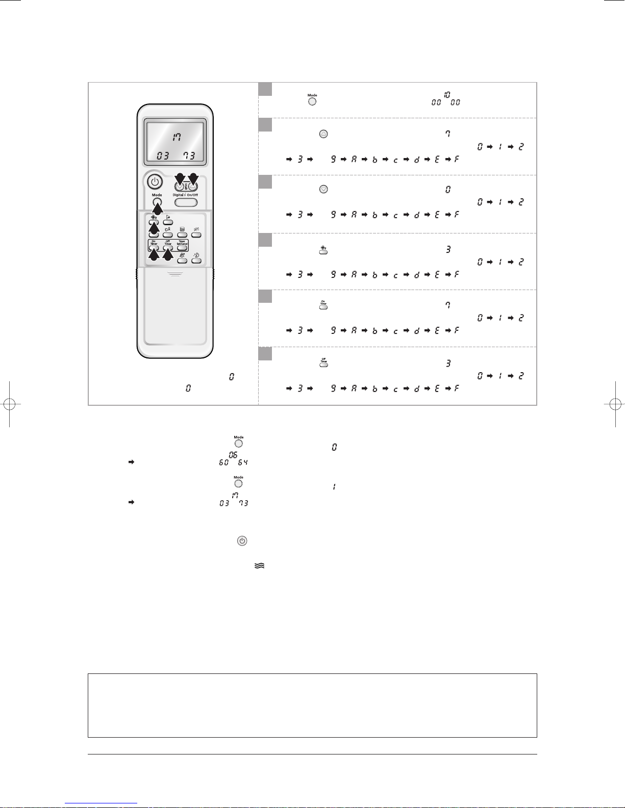
3-2 Setting Option Setup Method
ex) Option No. :
Step 1 : Enter the Option Setup mode.
st
1
2
3
Step 2 : Enter the Option Setup mode and select your option according to the following procedure.
Take out the batteries of remote control.
nd
Press the temperature button simultaneously and
insert the battery again.
rd
Make sure the remocon display shown as .
1
The default value is .
Otherwise, push the button to .
Every time you push the button, the display panel reads or
repeatedly.
3 2
1
4
5 6
✳ Setting is not required if you must
a value which has a default.
2
Push the button to set the display panel to .
Every time you push the button, the display panel reads
. . .
3
Push the button to set the display panel to .
Every time you push the button, the display panel reads
. . .
4
Push the button to set the display panel to .
Every time you push the button, the display panel reads
. . .
5
Push the button to set the display panel to .
Every time you push the button, the display panel reads
. . .
6
Push the button to set the display panel to .
Every time you push the button, the display panel reads
. . .
repeatedly.
repeatedly.
repeatedly.
repeatedly.
repeatedly.
3-5Samsung Electronics
Alignment and Adjustments
9 8
7
10
11 12
7
Press button, then the default value is .
8
Push the button to set the display panel to .
Every time you push the button, the display panel reads
. . .
9
Push the button to set the display panel to .
Every time you push the button, the display panel reads
. . .
10
Push the button to set the display panel to .
Every time you push the button, the display panel reads
. . .
11
Push the button to set the display panel to .
Every time you push the button, the display panel reads
. . .
repeatedly.
repeatedly.
repeatedly.
repeatedly.
12
Push the button to set the display panel to .
✳ Setting is not required if you must
a value which has a default.
Step 3 : Upon completion of the selection, check you made right selections.
Press the Mode Selection key, to set the display part to and check the display part.
The display part shows .
Press the Mode Selection key, to set the display part to and check the display part.
The display part shows .
Step 4 : Pressing the ON/OFF button ( )
When pressing the operation ON/OFF key with the direction of remote control for unit, the sound ''Ding'' or ''Diriring''
is heard and the OPERATION ICON( ) lamp of the display is flickering at the same time, then the input of option is
completed. (If the diriring sound isn't heard, try again pressing the ON/OFF button.)
Step 5 : Unit operation test-run
First, Remove the battery from the remote control.
Second, Re-insert the battery into the remote control.
Third, Press ON/OFF key with the direction of remote control for set.
Every time you push the button, the display panel reads
. . .
repeatedly.
• Error Mode
st
1
If all lamps of indoor unit are flickering, plug out, plug in power plug again and press the ON/OFF key to retry.
nd
If the unit is not working properly or all lamps are continuously flickering after setting the option code, see if the correct option code
2
is set up for its model.
Samsung Electronics3-6

■ OPTION ITEMS
REMOCON
MODEL
Alignment and Adjustments
SEG1 SEG2 SEG3 SEG4 SEG5 SEG6 SEG7 SEG8 SEG9 SEG10 SEG11 SEG12
AS09HPC
AS09HPD
AS12HPC
AS12HPD
027024171218
027024170218
027026171269
027026170269
3-7Samsung Electronics

4. Disassembly and Reassembly
Stop operation of the air conditioner and remove the power cord before repairing the unit.
4-1 Indoor Unit
No Parts Procedure Remark
1 Panel Front
1) Stop the air conditioner operation and
shut off the main power.
2) Detach the Front Grille after pushing
out it.
3) Loosen 1 of the right screw and detach
the Ass'y display.
4) Loosen 1 of the right screw and detach
the Terminal Cover.
5) Detach the cover PCB-DVM and
thermistor from the Panel Front.
Samsung Electronics4-1

Disassembly and Reassembly
No Parts Procedure Remark
6) Loosen 5 fixing screws of Panel Front.
7) Unlock 2 hooks to fix Panel Front and
Tray Drain.
8) Unlock 2 hooks to fix Panel Front and
Back Body.
2
3
Heat Exchanger
Tray Drain
1) Detach the connected wire of Stepping
Motor.
2) Pull Tray Drain out from the Back Body.
1) Loosen 1 fixing earth screw of right side.
4-2Samsung Electronics

Disassembly and Reassembly
No Parts Procedure Remark
2) Detach the Room Sensor.
3) Detach the Holder Pipe at the rear side
of the unit.
4) Loosen 3 fixing screws of left Holder
Evap.
5) Loosen 1 fixing screw of right Holder
Motor.
6) Detach the Heat Exchanger from the
indoor unit.
Samsung Electronics4-3
Disassembly and Reassembly
No Parts Procedure Remark
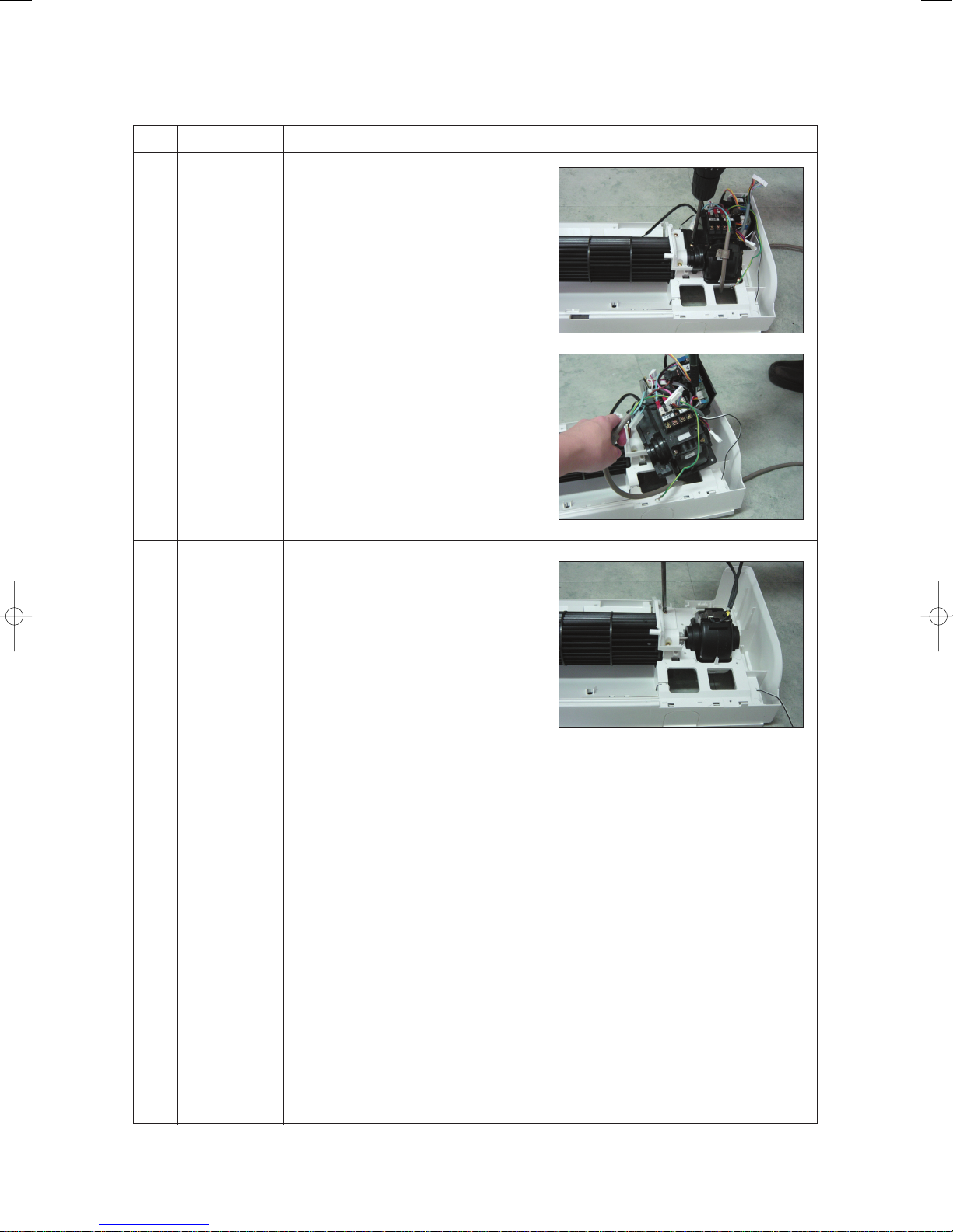
4
5
Electrical Parts
(Main PCB)
Fan Motor
&
Cross Fan
1) Loosen 4 fixing screws of right Holder
control.
2) Take all the connector of PCB upper side
out.(Including Power Cord)
3) Detach the outdoor unit connection wire
from the Terminal Block.
4) Pull the PCB up to detach.
1) Loosen 2 fixing screws and detach the
Motor Holder.
2) Loosen 1 fixing screw of Fan Motor.
3) Detach the Fan Motor from the Fan.
4) Detach the Fan from the left Holder
Bearing.
4-4Samsung Electronics
 Loading...