

Samsung AS09HPBN, AS12HPBN, AS09HPA, AS12HPA Training Manual

AS09HPBN
AS12HPBN
CONTENTS
Precautions 1
Product Specifications 2
Operating Instructions & Installation 3
Disassembly and Reassembly 10
Refrigerating Cycle Diagram 16
Feature & Operation 27
Set Up the Model Option 46
Troubleshooting 49
Exploded Views and Parts List 62
Block Diagram 67
PCB Diagram 68
Wiring Diagram 77
Schematic Diagram 79
1. Precautions
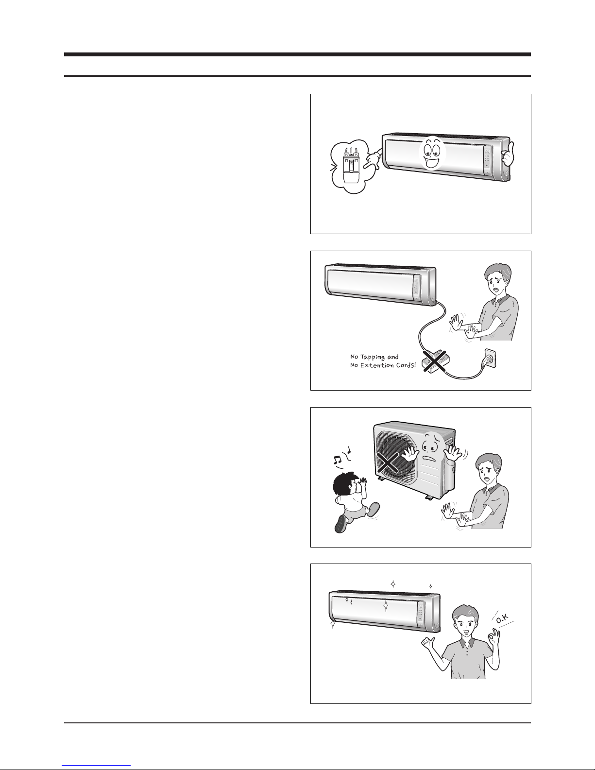
11) Cut off the power.
● Make sure to cut off the power before repair. If not, you may
be damaged by an electric shock.
12) Do not install an outdoor unit on the apartment outside
wall(or equivalent) for safety.
● Installing an outdoor unit on the apartment outside wall(or
equivalent) is prohibited for the safety purpose. Service will
not be available for the outdoor unit where our servicemen
can not access and the cost of moving the outdoor unit to
the service area will be borne by the customer.
● If requested by the customer, you shall discourage him to
install an outdoor unit on the apartment outside wall(or
equivalent).
13) The air conditioner outdoor unit shall be installed 2m
above ground and kept away from pedestrians to prevent
direct exposure to hot wind. (according to the Building
Facility Standard Regulations)
14) Keep the drain hose outlet free.
● Otherwise, air flow will get slow, which may hinder cooling
capacity.
● Also, dew may be laden on the service valve.
15) Use of Certified Parts
● Use certified parts only. (An electric contact part, if broken
down, shall not be repaired but replaced with a new one.
Remodeling shall be prohibited. In no case, the customer
shall repair the product on his own because this is dangerous enough to bring about breakdown or fire.)
16) Ban on Middle Connection of Power Cord
● Do not cut the power cord in the middle to be connected to
other power cord nor use a middle socket between two
power cords. This is dangerous enough to bring about
breakdown or fire.
17) Check Insulation
● After assembly, be sure to check insulation resistance.
(Use an insulation ohmmeter to measure the insulation
resistance between the power cord and the earthing wire.
Do not supply power until it reads 30MΩ.)
18) Be sure to keep the symmetry of the product.
● Otherwise, you may hear vibration noise.
19) Caution for Children
● Do not keep children off the product while it is in repair.
Otherwise, they might be endangered.
10) Be sure to put the indoor or outdoor unit free of corrosive
gases such as sulfuric water, ammonium, and sulfuric
gas.
● Otherwise, copper tubes or soldered parts could be
corroded causing refrigerant leak.
11) Arrangement of surroundings
● After repair finishes, clean the air conditioner and its
surroundings and inform the customer of what it is like.
1Samsung Electronics
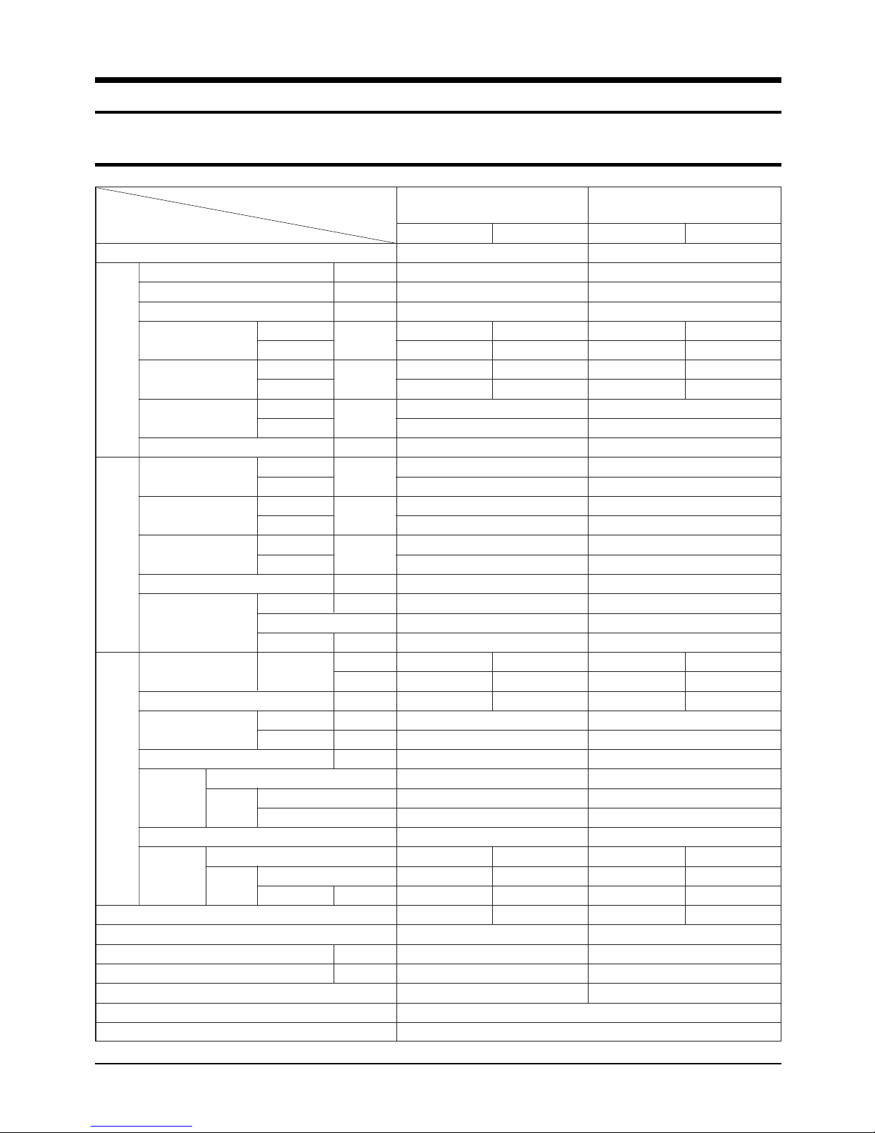
2. Product Specifications
2-1 Table
Item
Type
Cooling kW
Heating kW
Dehumidifying |/h
Air Volume
Performance
Noise
Energy Efficiency Ratio
Power ph-V-Hz
Power Consumption
Operating Current
Powe r
Power Factor
Starting Current A
Power Cord Number of Core Wire
Outer Dimension
Weight(Net) kg
Refrigerant Pipe
Drain Hose D x L(mm)
Size
Compressor Motor Type
Oil Type
Blower Motor Type
Heat Exchanger
Refrigerant Control Unit
Freezer Oil Capacity cc
Refrigerant to Change(R410A) g
Protection Device(OLP)
Cooling Test Condition
Maximum Operation Condition
Type
Type
Cooling
Heating
Cooling
Heating
Cooling
Heating
Cooling
Heating
Cooling
Heating
Cooling
Heating
Length m
Capacity A
Width x Height
x Depth
Liquid mm x L(m)
Gas mm x L(m)
Rated Output
Rated Output W
Model
3
m
/min
(H/M/L)
dB
(H/M/L)
W/W
W
A
%
mm
inch
AS09HPBN AS12HPBN
Indoor unit Outdoor unit
Wall-mounted
2.70
2.90
1.0
7.5/6.9/6.3 25
8.0/7.4/6.8 25
40/36/32 51/51
40/36/32 51/51
3.21
3.41
1-220/240-50
840
850
3.9
3.7
93.6
99.9
21
2.1
5G
250V-10A
950 x 268 x 165 790 x 548x 285
37.4 x 10.6 x 6.5 31.1 x 21.6 x 11.2
9.0 33.8
ø6.35 x 7.5
ø9.52 x 7.5
ø18 x 550
Rotary, G4A091JU
Induction Motor(PSC)
930
DAPHNE FV68S(PVE)
Cross-flow Propeller
Resin / steel steel
15 50
2ROW 12STEP 1ROW 24STEP
CAPILLARY TUBE
280
730
RBC12054-12500
INDOOR UNIT : DB27˚C WB19˚C OUTDOOR UNIT : DB35˚C WB24˚C
INDOOR UNIT : DB32˚C WB23˚C OUTDOOR UNIT : DB43˚C WB26˚C
Indoor unit Outdoor unit
Wall-mounted
3.50
3.80
1.4
8.3/7.0/5.7 25
9.5/8.9/8.3 25
43/38/34 53/53
43/38/34 53/53
3.21
3.22
1-220/240-50
1,090
1,180
5.0
5.4
94.8
95.0
28
2.1
5G
250V-10A
950 x 268 x 165 790 x 548x 285
37.4 x 10.6 x 6.5 31.1 x 21.6 x 11.2
9.0 36.0
ø6.35 x 7.5
ø9.52 x 7.5
ø18 x 550
Rotary, G8C124JU
Induction Motor(PSC)
1,267
DAPHNE FV68S(PVE)
Cross-flow Propeller
Resin / steel steel
15 50
2ROW 12STEP 2ROW 24STEP
CAPILLARY TUBE
500
950
RBC12128-12500
Samsung Electronics2
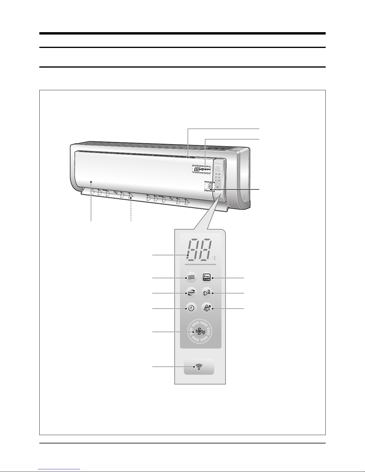
3. Operating Instructions & Installation
3-1 View of the Unit
3-1-1 Indoor Unit
Air Inlet
Room Temperature sensor
Power(On/Off) button
Air filter
(under the grille)
Operation indicator
(Auto-Cool, Cool, Dry, Fan : Blue
Auto-Heat, Heat : Orange)
Turbo function indicator
Fan speed indicator
Remote control sensor
Airflow blades
(outlet)
Set temperature &
room temperature
(Blue)
Timer indicator
(Orange)
(Blue)
Auto cleaning indicator
(Blue)
Energy saving indicator
(Blue)
Anion indicator
(Blue)
3Samsung Electronics
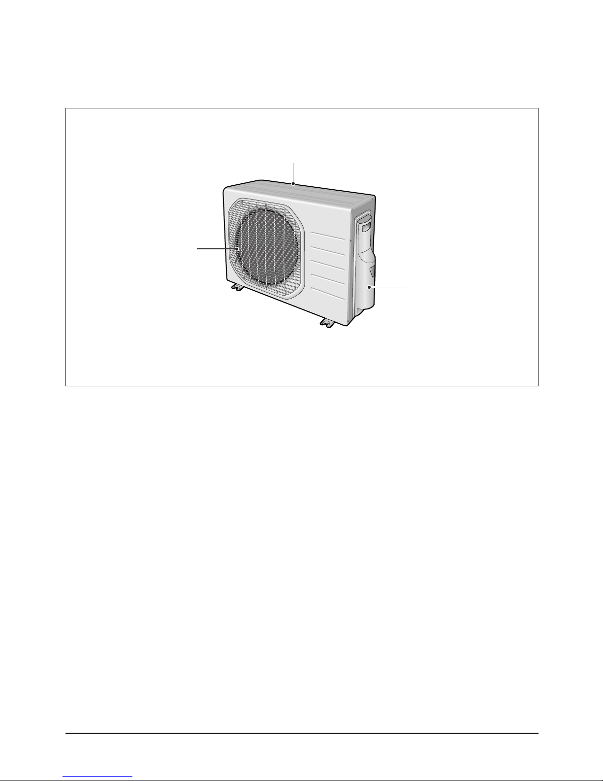
Operating Instructions & Installation
3-1-2 Outdoor Unit
Air Outlet
Air Inlet(Rear)
Connection Valve
(inside)
Samsung Electronics4
3-2 Air Conditioner and Accessories
O
W
N
E
R
’
S
I
N
S
T
R
U
C
T
I
O
N
S
M
A
N
U
A
L
D
E
I
N
S
T
R
U
C
C
I
O
N
E
S
I
S
T
R
U
Z
I
O
N
I
P
E
R
L
’
U
S
O
M
A
N
U
A
L
D
E
I
N
S
T
R
U
˝
E
S
M
A
N
U
E
L
D
’
U
T
I
L
I
S
A
T
I
O
N
G
E
B
R
A
U
C
H
S
A
N
W
E
I
S
U
N
G
S
p
l
u
t
-
t
y
p
e
R
o
o
m
A
i
r
C
o
n
d
i
t
i
o
n
e
r
A
i
r
e
a
c
o
n
d
i
c
i
o
n
a
d
o
d
o
m
s
t
i
c
o
s
i
s
t
e
m
a
S
p
l
i
t
C
o
n
d
i
z
i
o
n
a
t
o
r
e
d
’
a
r
i
a
p
e
r
a
m
b
i
e
n
t
i
a
d
u
n
i
t
S
e
p
a
r
a
t
e
A
p
a
r
e
l
h
o
d
e
a
r
c
o
n
d
i
c
i
o
n
a
d
o
t
i
p
o
S
p
l
i
t
C
l
i
m
a
t
i
s
e
u
r
d
e
t
y
p
e
s
p
a
r
G
e
t
e
i
l
t
e
r
a
u
m
k
l
i
m
a
a
n
l
a
g
e
O
W
N
E
R
’
S
I
N
S
T
R
U
C
T
I
O
N
S
M
A
N
U
A
L
D
E
I
N
S
T
R
U
C
C
I
O
N
E
S
I
S
T
R
U
Z
I
O
N
I
P
E
R
L
’
U
S
O
M
A
N
U
A
L
D
E
I
N
S
T
R
U
˝
E
S
M
A
N
U
E
L
D
’
U
T
I
L
I
S
A
T
I
O
N
G
E
B
R
A
U
C
H
S
A
N
W
E
I
S
U
N
G
S
p
l
u
t
-
t
y
p
e
R
o
o
m
A
i
r
C
o
n
d
i
t
i
o
n
e
r
A
i
r
e
a
c
o
n
d
i
c
i
o
n
a
d
o
d
o
m
s
t
i
c
o
s
i
s
t
e
m
a
S
p
l
i
t
C
o
n
d
i
z
i
o
n
a
t
o
r
e
d
’
a
r
i
a
p
e
r
a
m
b
i
e
n
t
i
a
d
u
n
i
t
S
e
p
a
r
a
t
e
A
p
a
r
e
l
h
o
d
e
a
r
c
o
n
d
i
c
i
o
n
a
d
o
t
i
p
o
S
p
l
i
t
C
l
i
m
a
t
i
s
e
u
r
d
e
t
y
p
e
s
p
a
r
G
e
t
e
i
l
t
e
r
a
u
m
k
l
i
m
a
a
n
l
a
g
e
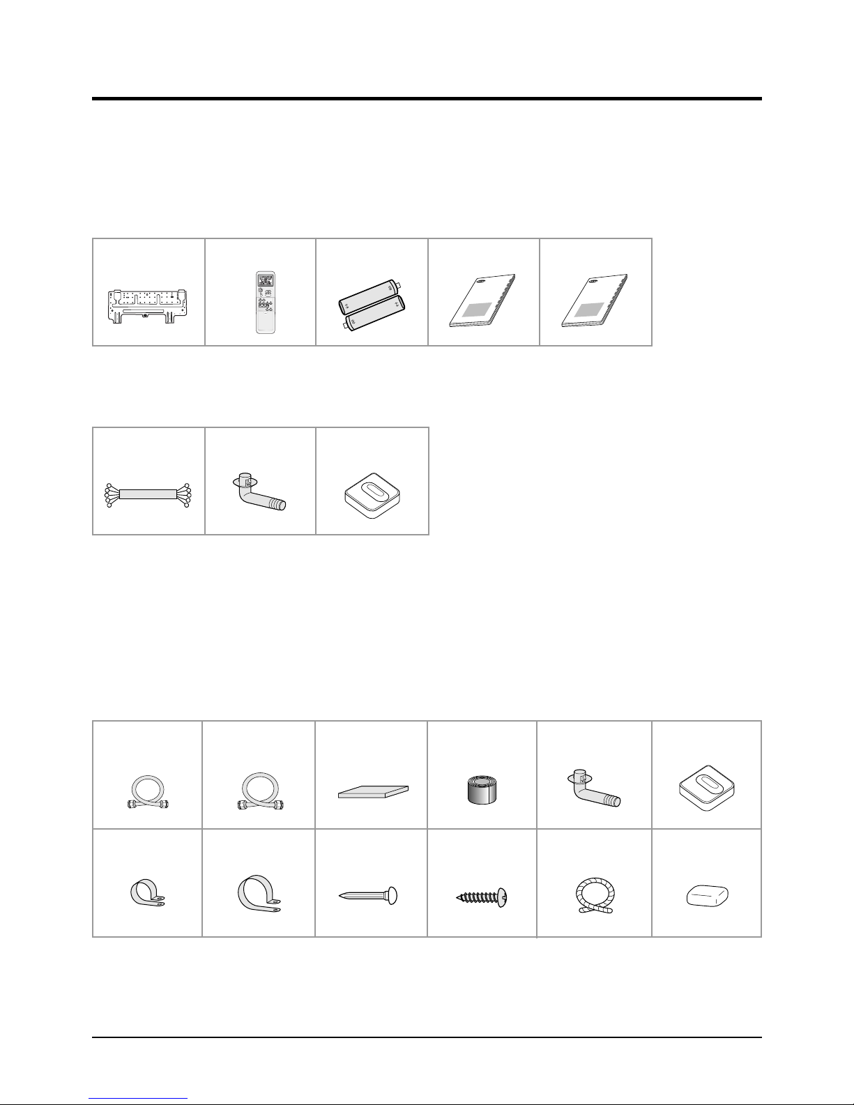
The following accessories are supplied with the air conditioner.
- The number of each accessory is indicated in parentheses.
3-2-1 Accessories in the Indoor Unit Case
Installation Plate (1) Remote Control (1) Batteries for
Remote Control (2)
User’s Manual (1) Installation Manual (1)
3-2-2 Accessories in the Outdoor Unit Case
5-wire
Assembly Cable (1)
- The flare nuts are attached to the end of each pipe of an evaporator or a service port.
Use the nuts when connecting the pipes.
- The 5-wire assembly cable is optional. If it is not supplied, use the standard cable.
- The drain plug and rubber leg are only included when the air conditioner is supplied without the assembly pipe as seen in the
picture below.
Drain Plug (1) Rubber Leg (4)
The following connection accessories are optional.
If they are not supplied, you should prepare them before installing the air conditioner.
Assembly Pipe, ø6.35mm
by 7.5m (1)
Pipe Clamps A (3) Pipe Clamps B (3) Cement Nail (6) M4 x 16 Tapping
Assembly Pipe, ø9.52mm
by 7.5m (1)
PE T3 Foam Tube
Insulation (1)
Vinyl Tape,
Width 50mm (1)
Screws (10)
Drain Plug (1) Rubber Leg (4)
Drain Hose,
length 2m (1)
Putty 100g (1)
- If these accessories are supplied, you can find them in the accessory box.
5Samsung Electronics

3-3 Installation
D
A
3-3-1 Before Installation
Keep the air conditioner outlet and inlet free from its surroundings.
In case of installation, keep the symmetry and fix it to prevent vibration.
The pipe length shall meet the standard as far as possible.
3-3-2 Installation Procedure
■ Location
Install the product in an area to guarantee the best cooling effect, convenience of piping and electric work, and inexistence of
vibration or wind.
■ Wall Drilling
Drill the wall downward in a diameter of 60 to 65mm.
■ Fixing Indoor Unit & Outdoor Unit
Fix the air conditioner indoor unit securely to the wall. Secure the outdoor unit in a suitable position.
■ Pipe Spooling & Connecting
You shall cut the pipe with a pipe cutter and grind all the burrs of the cut surface.
Pipe expansion may continue until the pipe surface becomes uneven or torn apart.
Be sure to use a torque wrench to tighten pipes or flare nuts.
<Torque & Depth>
Outer Diameter(D)
6.35mm(1/4")
9.52mm(3/8")
Torque
140~170
250~280
(kgf.cm)
Depth
1.3mm
1.8mm
(A)
■ Leak Test
Put an inert gas like nitrogen in the outdoor unit pipe and put soap bubbles or other test liquids on the pipe surface for the leak test.
■ Drain Hose Connecting
Install the drain hose downward to drain water naturally. Be sure to pour water into the hose to check if it drains well.
■ Electric & Earth Work
Electric and earth work shall meet the "Electric Facility Technology Standard" and the "Internal Wire Regulation" of the Electric
Business Laws.
■ Inspection & Trial Run
Upon completion of the tests, you shall make a trial run while you explain the main functions of the air conditioner to finish the
installation.
Samsung Electronics6
3-4 Installation Diagram of Indoor Unit and Outdoor Unit
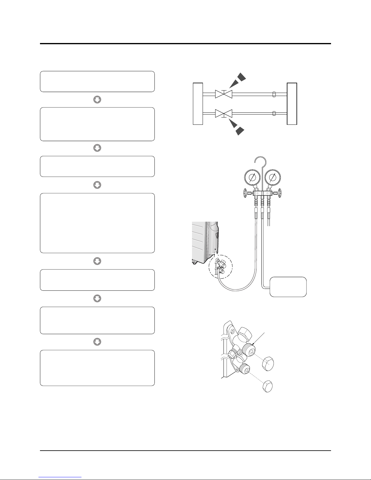
3-4-1 Air-Purge Procedure
1) Connect each assembly pipe to the appropriate
valve on the outdoor unit and tighten the flare nut.
2) Connect the charging hose of low pressure side
of manifold gauge to the packed valve having a
service port (3/8" Packed valve) as shown at the
figure.
3) Open the valve of the low pressure side of
manifold gauge counter-clockwise.
4) Purge the air from the system using vacuum
pump for about 30 minutes.
- After that, please recheck that pressure is
stabilized.
- Close the valve of the low pressure side of
manifold gauge clockwise.
- Remove the hose of the low pressure side
of manifold gauge.
Outdoor unit
Indoor unit
A
B
Gas pipe side
Liquid pipe side
C
D
5) Set valve cork of both liquid side and gas side of
packed valve to the open position.
6) Mount the valve stem nuts to the 2-Way and
3-Way valve. And mount the service port cap to
3-Way valve.
7) Check for gas leakage.
- At this time, especially check for gas
leakage from the 3-Way valve’s stem nuts,
and from the service port cap.
Valve stem
Stem cap
Vacuum Pump
A
(gas)
B
(liquid)
7Samsung Electronics
Operating Instructions & Installation
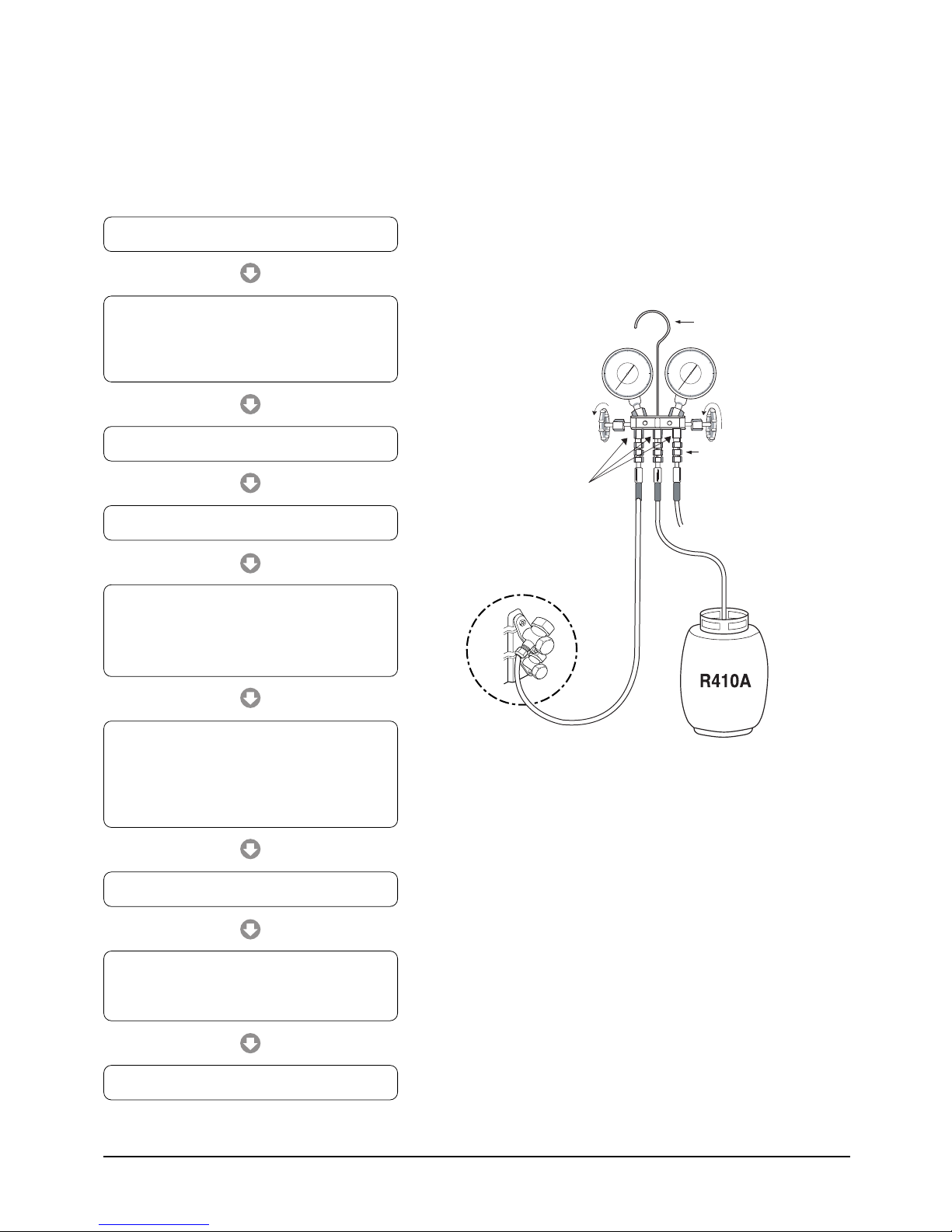
3-4-2 Refrigerant Refill(R410A)
Refill an air conditioner with refrigerant when refrigerant has been leaked at installing or using.
1) Purge air(for new installation only).
2) Turn the 3-Way valve clockwise to close,
connect the pressure gauge (low pressure side) to
the service valve, and open the 3-Way valve
again.
3) Connect the tank to refill with refrigerant.
4) Set the unit to cool operation mode.
5) Check the pressure indicated by the pressure
gauge(low pressure side).
* Standard pressure is should be 9.0~10.0kg/cm
in a regular, high operation mode.
6) Open the refrigerant tank and fill with refrigerant
until the rated pressure is reached.
* It is recommended not to pour the refrigerant
in too quickly, but gradually while operating a
pressure valve.
Suspension hook
Compound
gauge
For mounting
other and of
hose when
not in use
2
High
pressure
gauge
Hand
wheel
Finger tight
fittings
Connected to
high pressure
side
Charging line
7) Stop operation of the air conditioner.
8) Close the 3-Way valve, disconnect the
pressure gauge, and open the 3-Way valve
again.
9) Close the cap of each valve.
Samsung Electronics8
Operating Instructions & Installation
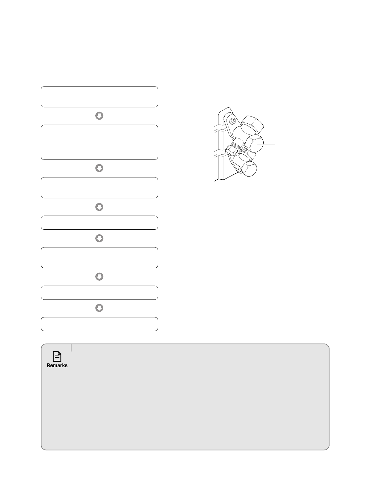
3-4-3 "Pump down" Procedure
Pump down will be carried out when an evaporator is replaced or when the unit is relocated in another area.
1) Remove the caps from the 3-Way valve and the
3-Way valve.
2) Turn the 3-Way valve clockwise to close and
connect a pressure gauge (low pressure side)
to the service valve, and open the 3-Way valve
again.
3) Set the unit to cool operation mode.
(Check if the compressor is operating.)
3-Way Valve
2-Way Valve
4) Turn the 3-Way valve clockwise to close.
5) When the pressure gauge indicates "0" turn the
3-Way valve clockwise to close.
6) Stop operation of the air conditioner.
7) Close the cap of each valve.
Relocation of the air conditioner
• Refer to this procedure when the unit is relocated.
• Carry out the pump down procedure (refer to the details of 'pump down').
• Remove the power cord.
• Disconnect the assembly cable from the indoor and outdoor units.
• Remove the flare nut connecting the indoor unit and the pipe.
• At this time, cover the pipe of the indoor unit and the other pipe using a cap or vinyl plug to avoid foreign
material entering.
• Disconnect the pipe connected to the outdoor unit.
At this time, cover the valve of the outdoor unit and the other pipe using a cap or vinyl plug to avoid foreign
material entering.
• Make sure you do not bend the connection pipes in the middle and store together with the cables.
• Move the indoor and outdoor units to a new location.
• Remove the mounting plate for the indoor unit and move it to a new location.
9Samsung Electronics
4. Disassembly and Reassembly
Stop operation of the air conditioner and electrically isolate before repairing the unit.
4-1 Indoor Unit
No Parts Procedure Remark
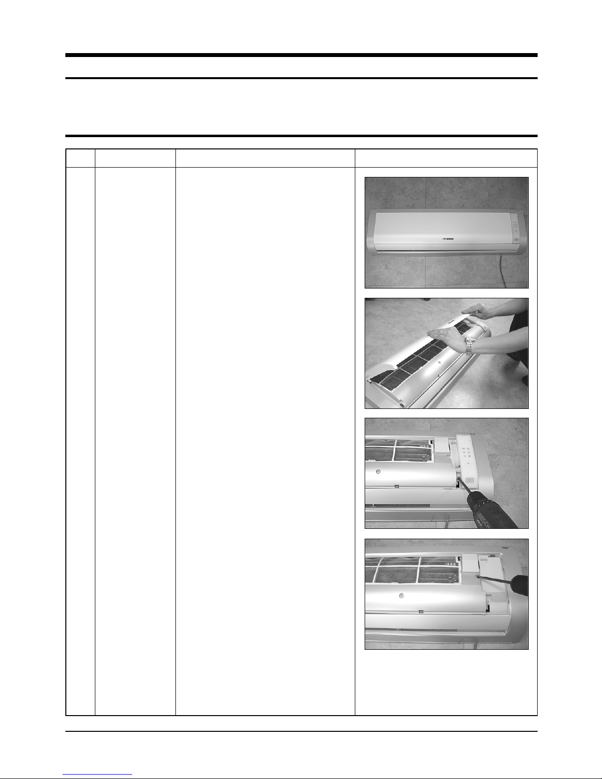
1 Panel Front
1) Stop the air conditioner operation and
shut off the main power.
2) Detach the Front Grille after pushing out it.
3) Loosen 1 of the right screw and detach
the Ass'y display.
4) Loosen 1 of the right screw and detach the
Terminal Cover.
5) Detach the cover PCB-DVM and thermistor
from the Panel Front.
Samsung Electronics10
Disassembly and Reassembly
No Parts Procedure Remark
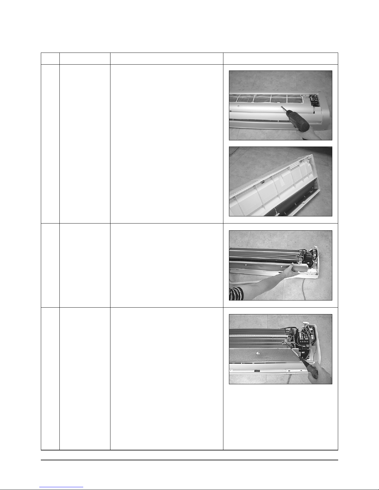
6) Loosen 5 fixing screws of Panel Front.
7) Unlock 2 hooks to fix Panel Front and
Tray Drain.
8) Unlock 2 hooks to fix Panel Front and
Back Body.
2
3
Tray Drain
Heat Exchanger
1) Detach the connected wire of Stepping
Motor.
2) Pull Tray Drain out from the Back Body.
1) Loosen 1 fixing earth screw of right side.
11Samsung Electronics
Disassembly and Reassembly
No Parts Procedure Remark
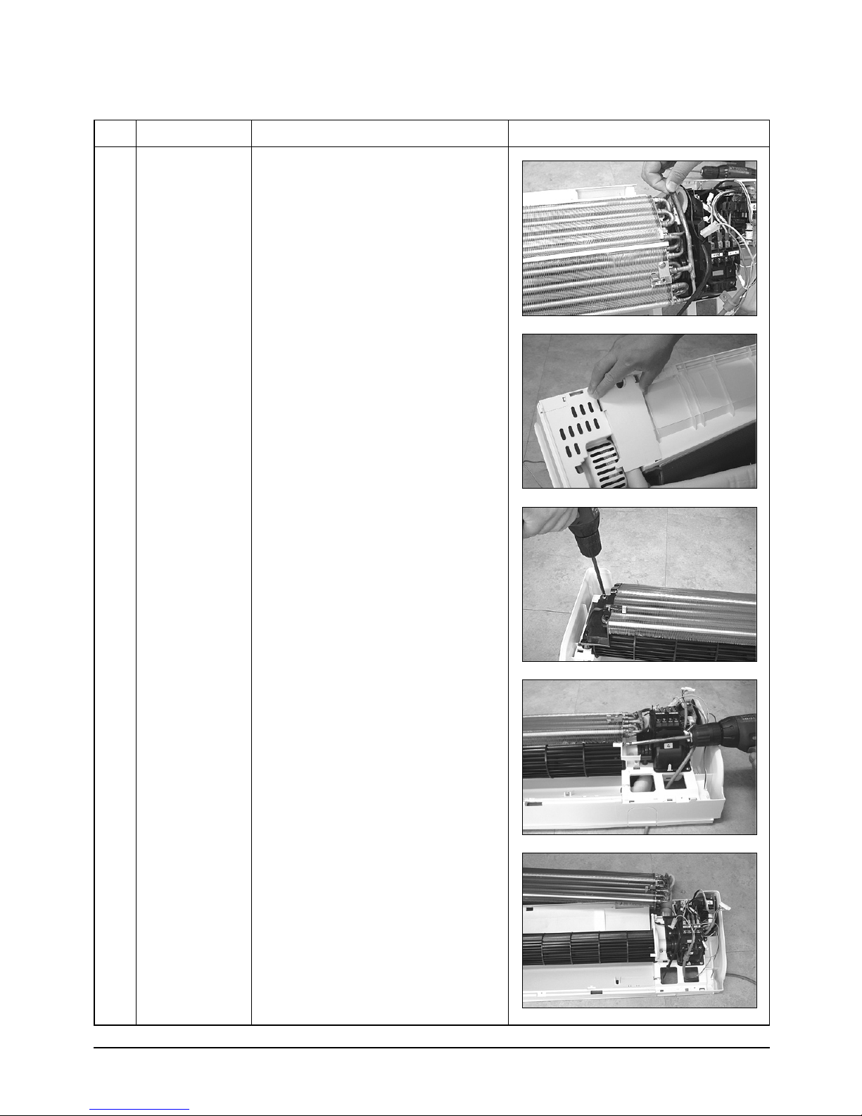
2) Detach the Room Sensor.
3) Detach the Holder Pipe at the rear side
of the unit.
4) Loosen 3 fixing screws of left Holder Evap.
5) Loosen 1 fixing screw of right Holder
Motor.
6) Detach the Heat Exchanger from the
indoor unit.
Samsung Electronics12
Disassembly and Reassembly
No Parts Procedure Remark
4
Electrical Parts
(Main PCB)
1) Loosen 4 fixing screws of right Holder
control.
2) Take all the connector of PCB upper side
out.(Including Power Cord)
3) Detach the outdoor unit connection wire
from the Terminal Block.
4) Pull the PCB up to detach.
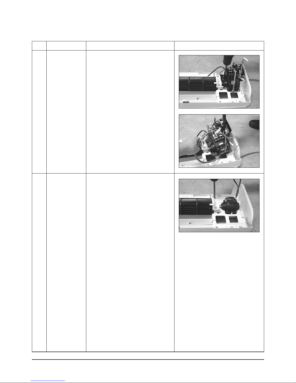
5
Fan Motor
&
Cross Fan
1) Loosen 2 fixing screws and detach the
Motor Holder.
2) Loosen 1 fixing screw of Fan Motor.
3) Detach the Fan Motor from the Fan.
4) Detach the Fan from the left Holder
Bearing.
13Samsung Electronics
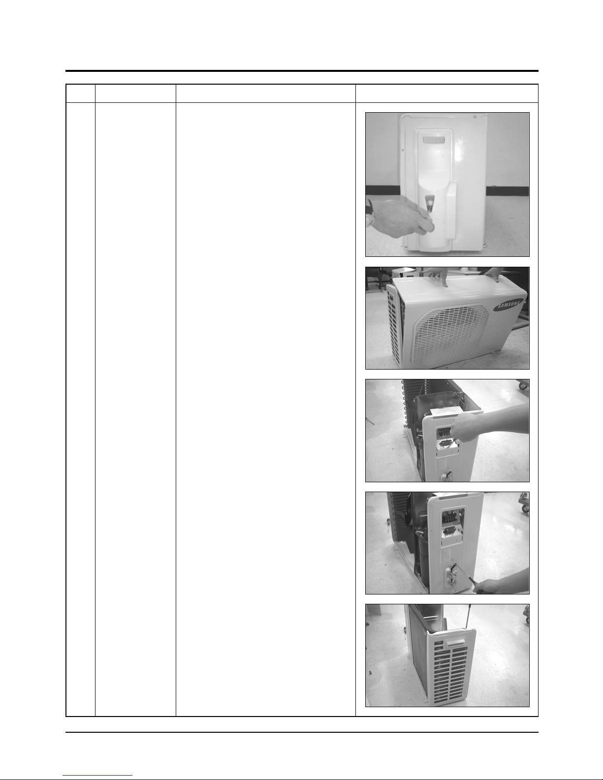
4-2 Outdoor Unit
No Parts Procedure Remark
1 Common Work
1) Loosen 1 fixing screw of the Cover-Side.
2) Loosen each 3 fixing screws on both right
and left Cabinet-Side edge and a fixing
screw on the Cabinet-Front lower to detach
the Cabinet-Front.
3) Loosen 6 fixing screws of the Cabinet-Side
RH.
4) Loosen 2 fixing screws of the Cabinet-Side
LF.
Samsung Electronics14
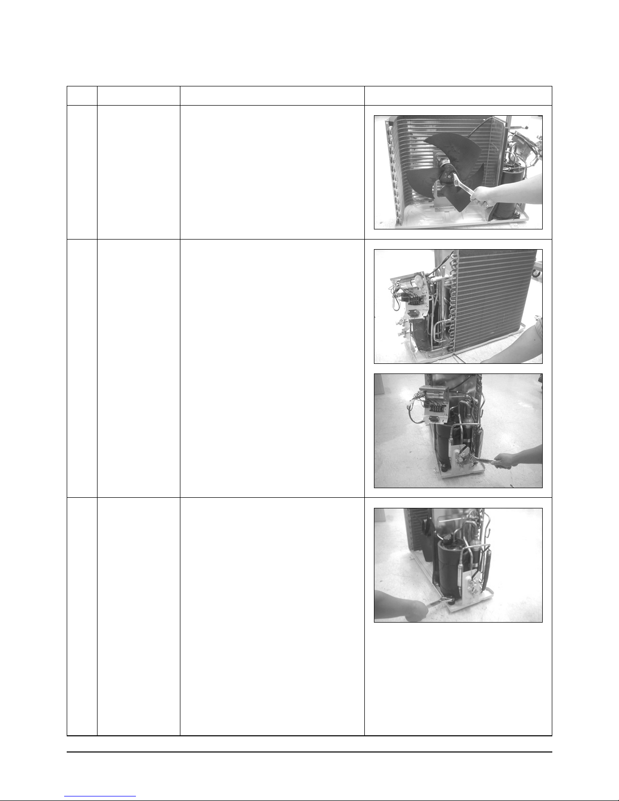
Disassembly and Reassembly
No Parts Procedure Remark
2
3
Fan & Motor
Heat Exchanger
1) Detach the Nut Flange.(Turn counterclockwise because the screw is right-handed)
2) Detach the Fan.
3) Loosen 4 fixing screws to detach
the Motor.
1) Loosen 2 fixing screws on both sides.
2) Disassemble the pipe in both inlet and
outlet with welding torch.
3) Detach the Heat Exchanger.
4
Compressor
1) Loosen the Terminal Cover nut to open the
Terminal Cover.
2) Disassemble the cloth sound felt.
3) Disassemble the pipe in both inlet and
outlet of the Compressor with welding
torch.
4) Disassemble the pipe in both inlet and
outlet of the Condenser with welding torch.
5) Loosen the 3 bolts at the bottom.
6) Detach the Compressor.
15Samsung Electronics
Cooling
Heating
Gas Leak Check Polnt
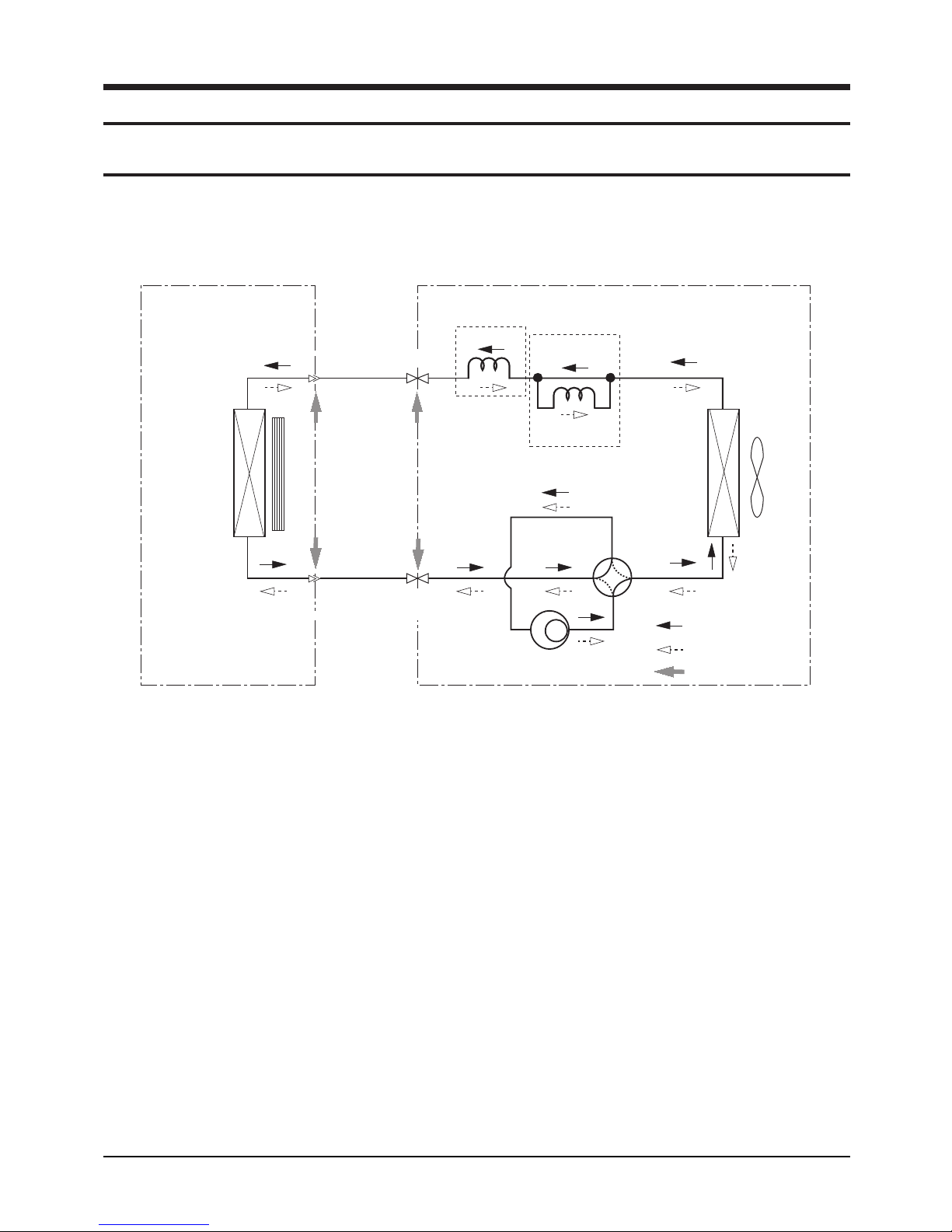
5. Refrigerating Cycle Diagram
5-1 Refrigerating Cycle Diagram
Indoor Unit
Heat
Exchanger
(Evaporator)
Outdoor Unit
T
1
Liquid side
Cross fan
T
2
Gas side
2-Way valve
3-Way valve
Capillary tube
✳Note
Check valve
Capillary tube
Heat
Exchanger
(Condenser)
Propeller fan
4-Way valve
Compressor
Samsung Electronics16
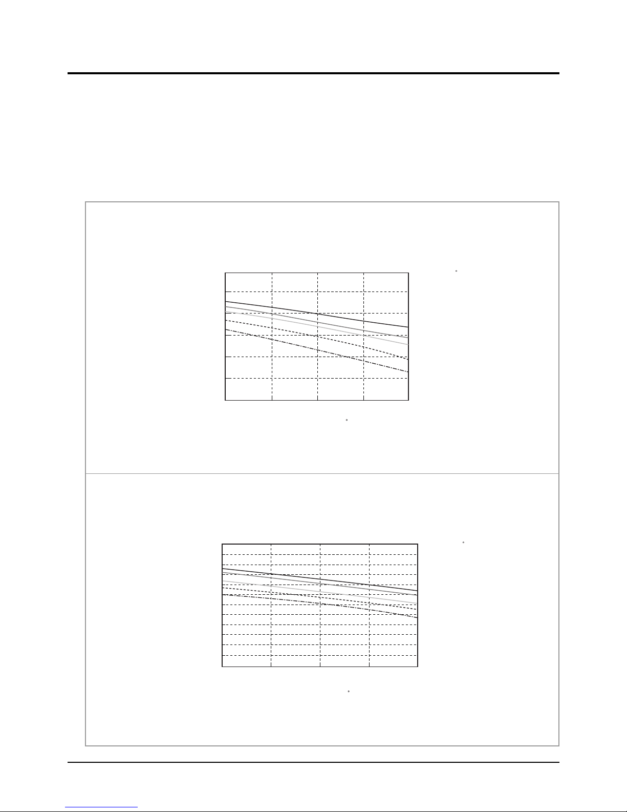
5-2 Refrigerant Cycle Characteristic
DB32.4/WB24.0
DB30.6/WB22.5
DB27.0/WB19.0
DB24.0/WB17.0
DB21.0/WB15.0
Cooling Capacity(kW)
Cooling Capacity Distribution
6.0
5.0
4.0
3.0
2.0
1.0
0.0
25 35 45
Outdoor Temp.(DB C)
Indoor Temp.( C)
5-2-1 Capacity Distributions
Capacity Distributions according to indoor and outdoor temperature variation.
■ COOLING MODE
- Indoor Temp. Variation : 21.0˚C ~ 32.4˚C
- Outdoor Temp. Variation : 25.0˚C ~ 45.0˚C
■ AS09HPBN
Cooling Capacity Distribution
■ AS12HPBN
4.0
3.0
2.0
Cooling Capacity(kW)
1.0
25.0 35.0 45.0
Outdoor Temp.(DB C)
Indoor Temp.( C)
DB32.4 / WB24.0
DB30.6 / WB22.5
DB27.0 / WB19.0
DB24.0 / WB17.0
DB21.0 / WB15.0
17Samsung Electronics
Refrigerating Cycle Diagram
DB15.0
DB20.0
DB25.0
Heating Capacity
Heating Capacity Distribution
6.00
5.00
4.00
3.00
2.00
1.00
0.00
1.0/0.0 7.0/6.0 20.0/15.0
Indoor Temp.( C)
Outdoor Temp.(DB/WB C)
■ HEATING MODE
- Indoor Temp. Variation : 15.0˚C ~ 25.0˚C
- Outdoor Temp. Variation : 1.0˚C ~ 20.0˚C
■ AS09HPBN
Heating Capacity Distribution
■ AS12HPBN
4.00
3.00
2.00
Heating Capacity(kW)
1.00
1.0/0.0 7.0/6.0 20.0/15.0
Outdoor Temp.(DB/WB C)
Indoor Temp.( C)
DB15.0
DB20.0
DB25.0
Samsung Electronics18

5-2-2 Power Consumption Distributions
Power consumption(W)
Power consumption Distribution(Cooling mode)
1,400
1,300
1,200
1,100
1,000
900
800
25 35 45
DB32.4 / WB24.0
DB30.6 / WB22.5
DB27.0 / WB19.0
DB24.0 / WB19.0
DB21.5 / WB15.0
Indoor Temp.( C)
Outdoor Temp.(DB C)
Power Consumption Distributions according to indoor and outdoor temperature variation.
■ COOLING MODE
- Indoor Temp. Variation : 21.0˚C ~ 32.4˚C
- Outdoor Temp. Variation : 25.0˚C ~ 45.0˚C
■ AS09HPBN
Power consumption Distribution(Cooling mode)
Refrigerating Cycle Diagram
■ AS12HPBN
1,100
1,000
900
800
700
Power consumption(W)
600
500
25 35 45
Outdoor Temp.(DB C)
Indoor Temp.( C)
DB32.4 / WB24.0
DB30.6 / WB22.5
DB27.0 / WB19.0
DB24.0 / WB19.0
DB21.5 / WB15.0
19Samsung Electronics
Refrigerating Cycle Diagram
Power consumption(W)
Power consumption Distribution(Heating mode)
1,500
1,400
1,300
1,200
1,100
1,000
900
25 35 45
DB25.0
DB20.0
DB15.0
Indoor Temp.( C)
Outdoor Temp.(DB/WB C)
■ HEATING MODE
- Indoor Temp. Variation : 15.0˚C ~ 25.0˚C
- Outdoor Temp. Variation : 1.0˚C ~ 20.0˚C
■ AS09HPBN
Power consumption Distribution(Heating mode)
■ AS12HPBN
1,050
950
850
750
Power consumption(W)
650
1.0/0.0 7.0/6.0 20.0/15.0
Indoor Temp.( C)
DB25.0
DB20.0
DB15.0
Outdoor Temp.(DB/WB C)
Samsung Electronics20
Refrigerating Cycle Diagram
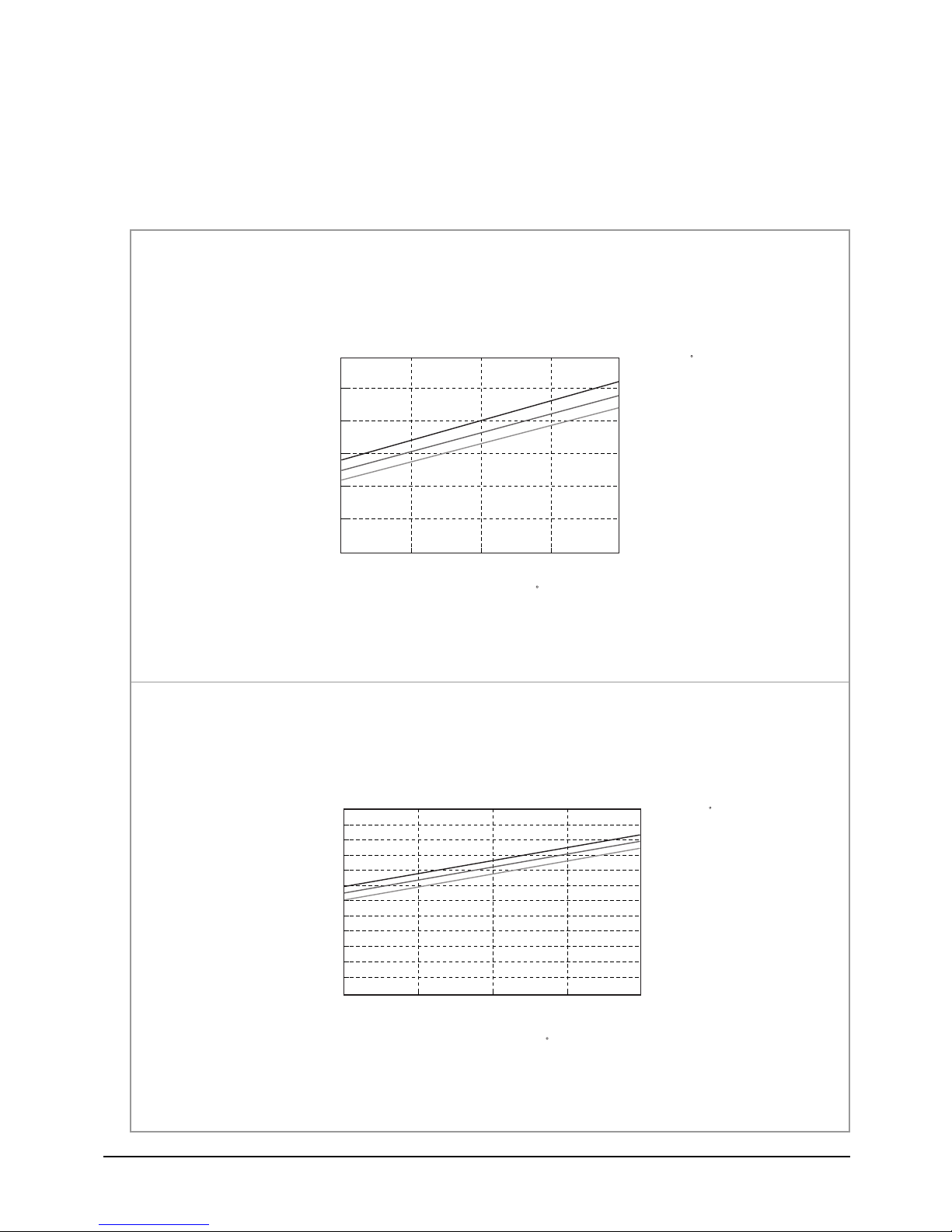
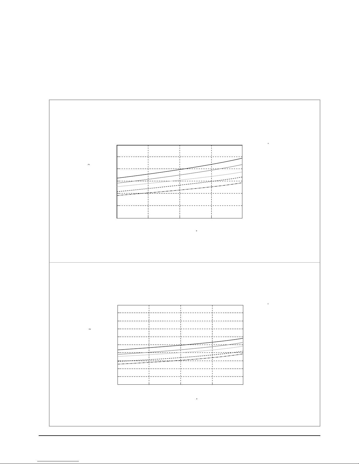
5-2-3 Capacity and Power Consumption Distributions
Capacity and power Consumption distributions according to the length of connecting Pipe between indoor unit and outdoor unit.
■ COOLING MODE
■ AS09HPBN
Coooling Capacity(kW)
■ AS12HPBN
Cooling Capacity
4
3
2
1
7.5 15.0
Length of Connecting Pipe(m)
Cooling Capacity
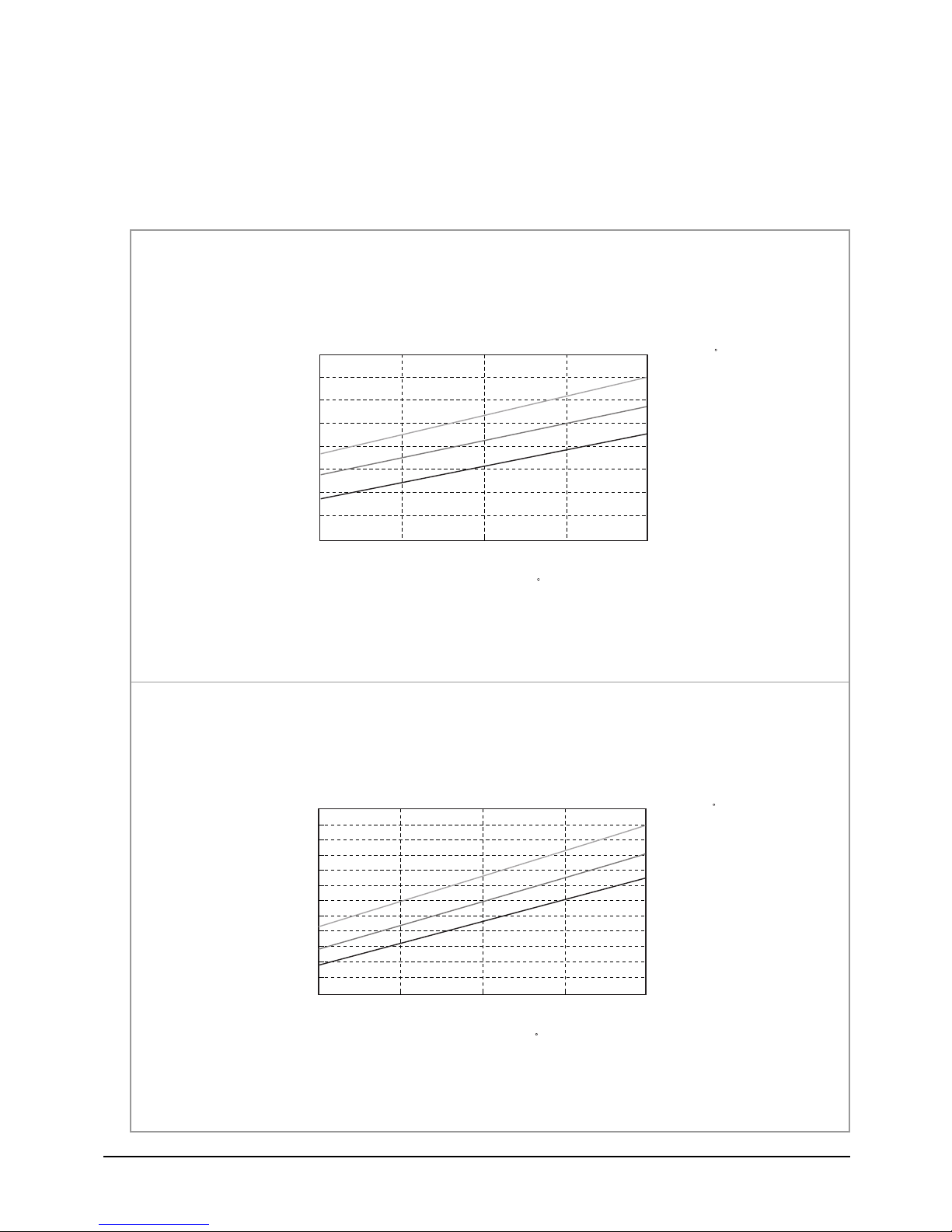
Power consumption(Cooling)
1,100
1,000
900
800
700
Power consumption(W)
600
500
7.5 15.0
Length of Connecting Pipe(m)
Power consumption(Cooling)
3.70
3.50
3.30
3.10
Cooling Capacity(kW)
2.90
7.5 15.0
Length of Connecting Pipe(m)
1,300
1,200
1,100
1,000
Power consumption(W)
900
7.5 15.0
Length of Connecting Pipe(m)
21Samsung Electronics
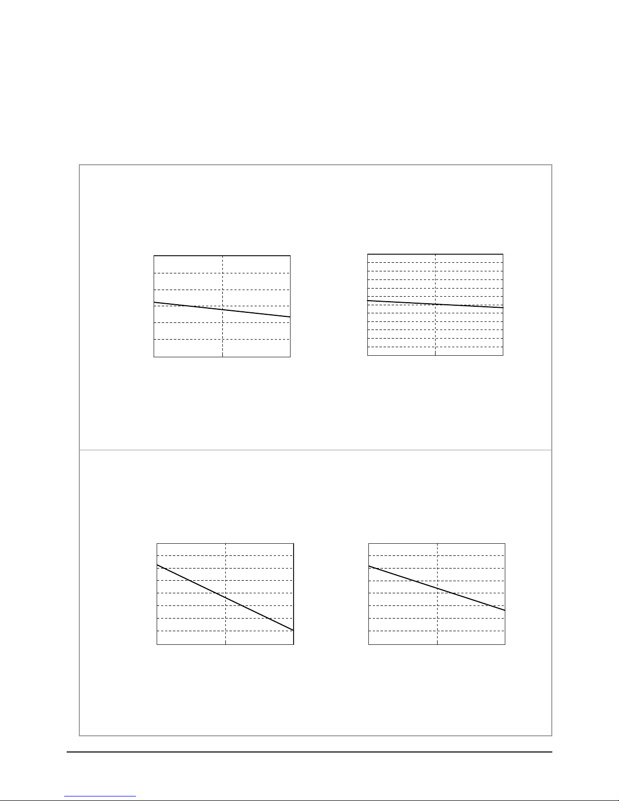
Refrigerating Cycle Diagram
■ HEATING MODE
■ AS09HPBN
4.00
3.00
2.00
Heating Capacity(kW)
1.00
■ AS12HPBN
Heating Capacity
7.5 15.0
Length of Connecting Pipe(m)
Power consumption(Heating)
1,050
950
850
750
Power consumption(W)
650
7.5 15.0
Length of Connecting Pipe(m)
Heating Capacity
4.30
4.10
3.90
3.70
Heating Capacity(kW)
3.50
7.5 15.0
Length of Connecting Pipe(m)
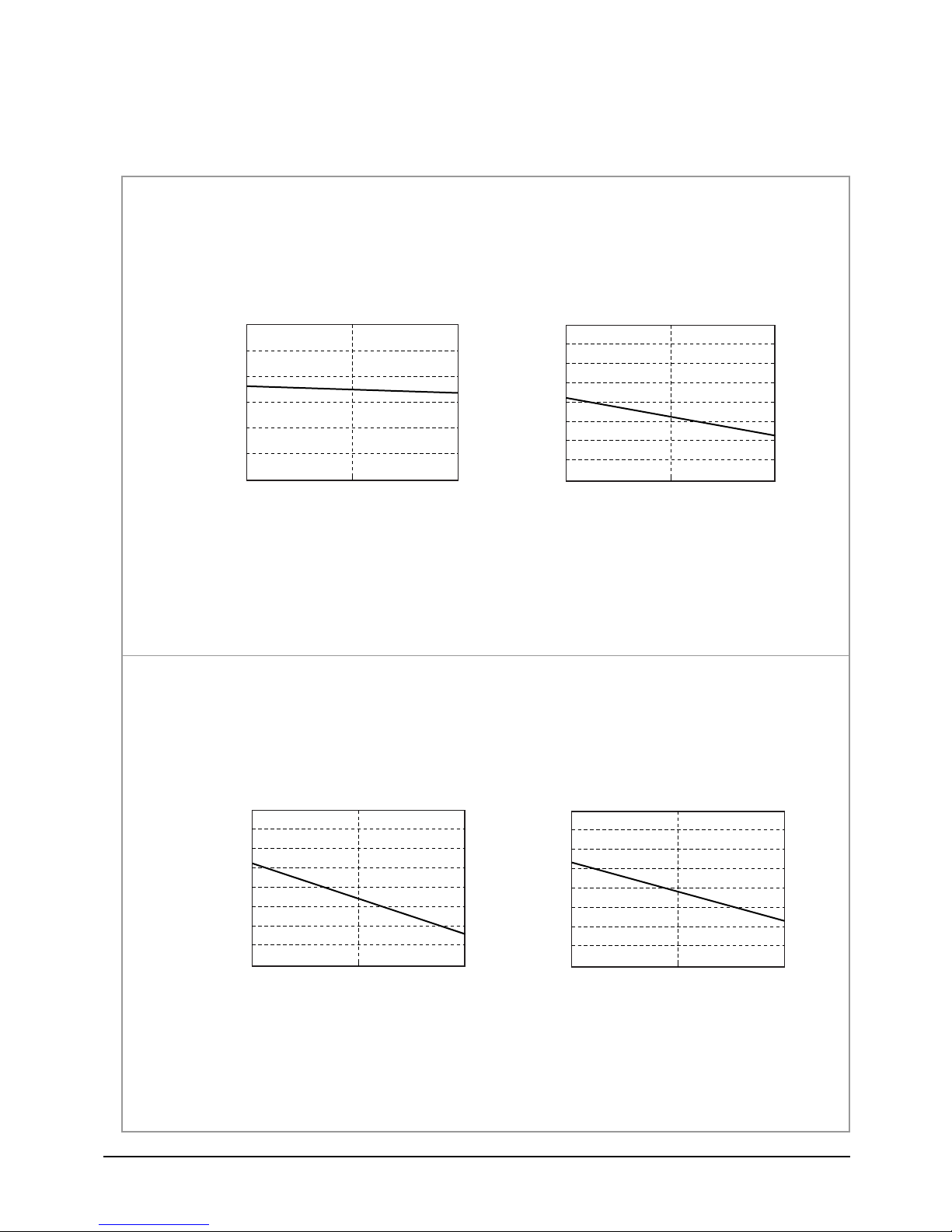
Power consumption(Heating)
1,350
1,250
1,150
1,050
Power consumption(W)
950
7.5 15.0
Length of Connecting Pipe(m)
Samsung Electronics22
5-2-4 Low Pressure Distributions
DB32.4 / WB24.0
DB30.6 / WB22.5
DB27.0 / WB19.0
DB24.0 / WB19.0
DB21.5 / WB15.0
Low pressure(kg/cm G)
Low Pressure Distribution(Cooling mode)
15.0
13.0
11. 0
9.0
7.0
5.0
25 35 45
Outdoor Temp.(DB C)
Indoor Temp.( C)
■ COOLING MODE
- Indoor Temp. Variation : 21.0˚C ~ 32.4˚C
- Outdoor Temp. Variation : 25.0˚C ~ 45.0˚C
■ AS09HPBN
Refrigerating Cycle Diagram
Low Pressure Distribution(Cooling mode)
■ AS12HPBN
12.0
10.0
8.0
Low pressure(kg/cm G)
6.0
25 35 45
Indoor Temp.( C)
DB32.4 / WB24.0
DB30.6 / WB22.5
DB27.0 / WB19.0
DB24.0 / WB17.0
DB21.0 / WB15.0
Outdoor Temp.(DB C)
23Samsung Electronics
Refrigerating Cycle Diagram
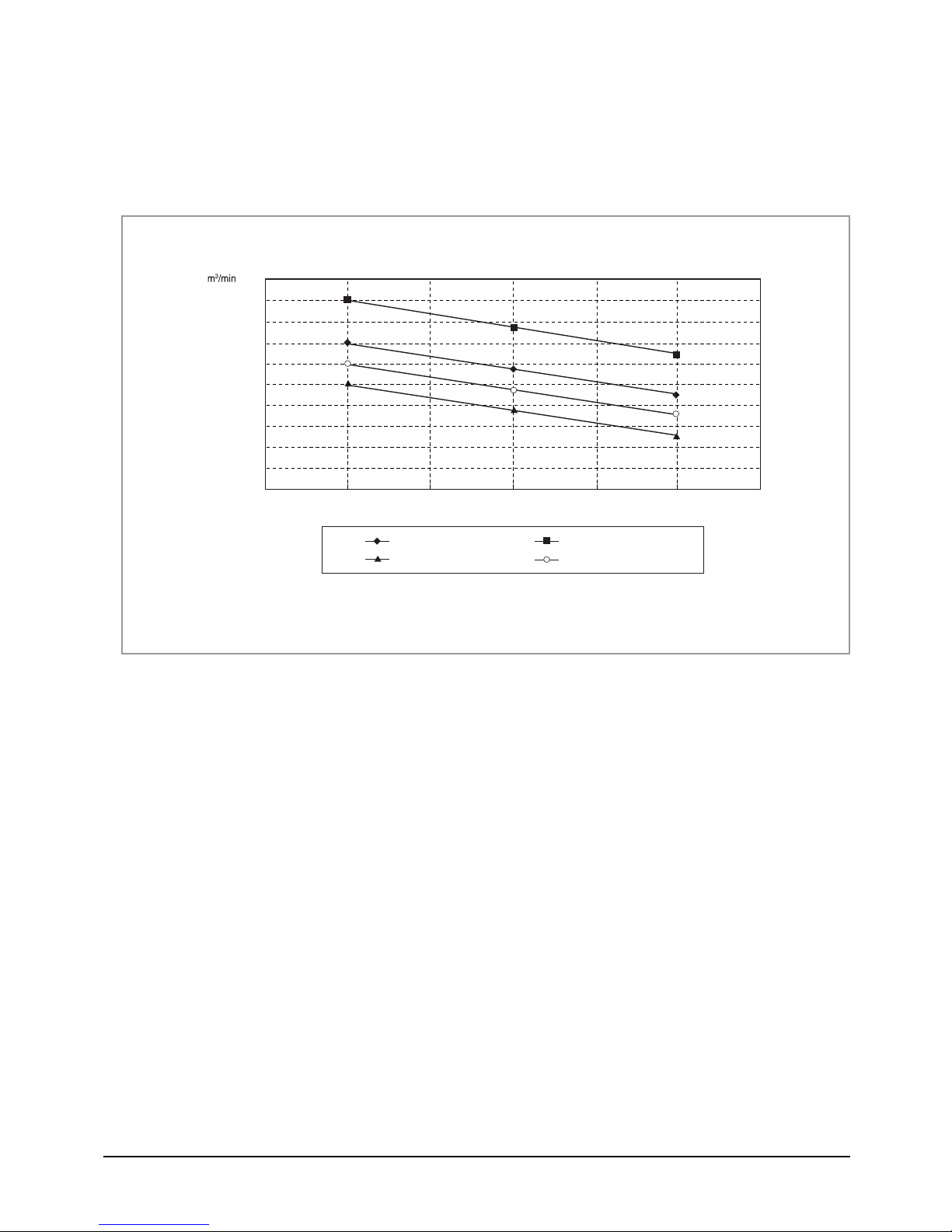
5-2-5 Air Volume according to the RPM variation(High/Mid/Low)
■ Indoor Unit
10
9.5
9
8.5
8
7.5
7
6.5
6
5.5
5
High Mid
Low
RPM
■ Outdoor Unit
The air volume is 25m3/min regardless of model.
12,000BTU-Cooling-Vol.
19,000BTU-Cooling-Vol.
12,000BTU-Heating-Vol.
19,000BTU-Heating-Vol.
Samsung Electronics24
 Loading...