

Samsung AS09HPB, AS12HPB, AS09BPA, AS12BPA, AS09BPA/XSA Service Manual
...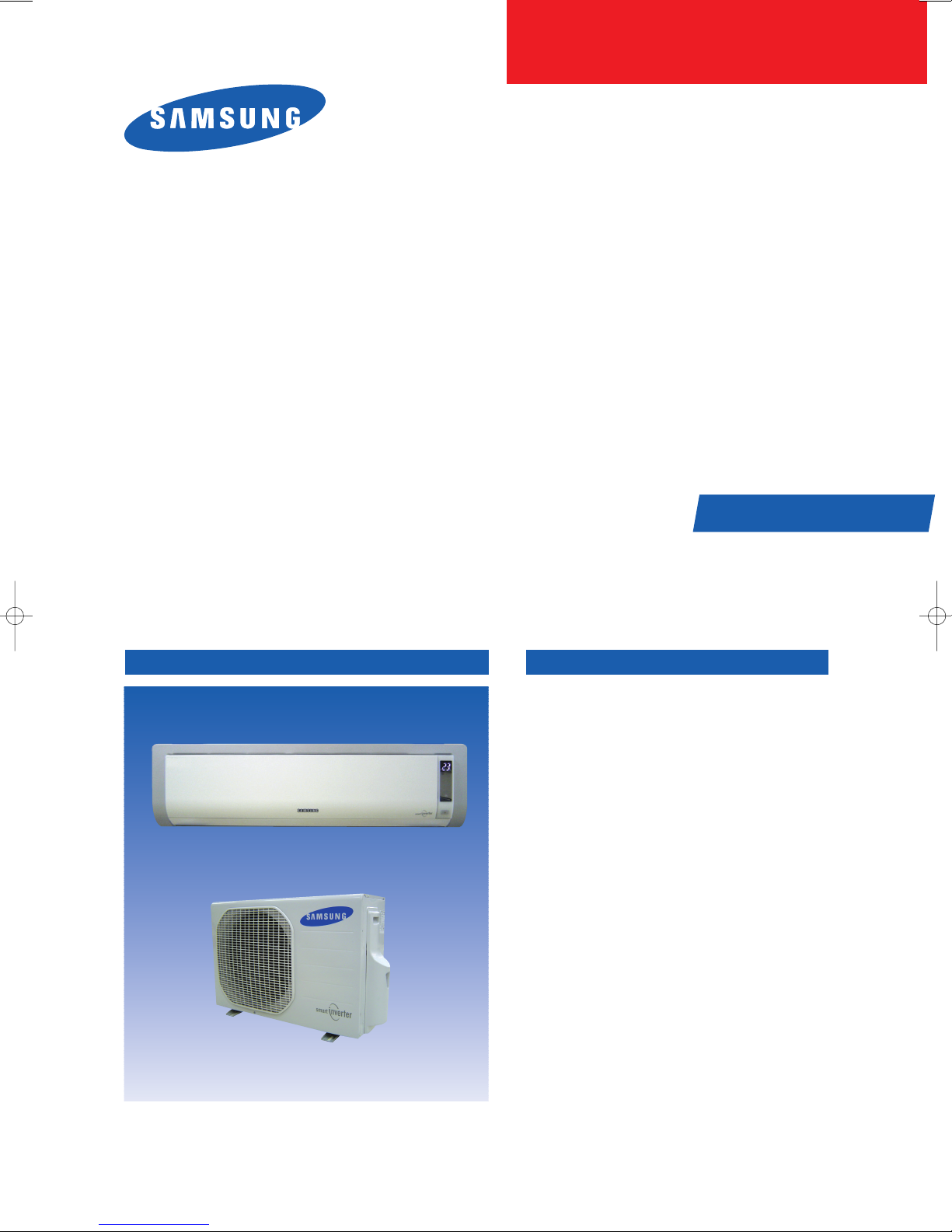
SPLIT-TYPE AIR CONDITIONER
Basic
Basic
Basic
Model
Model
Model
Model
Model Code: AS09BPAN AS09BPAX
Model Code
Model Code: AS09BPAN/XSA AS09BPAX/XSA
Model Code
SERVICE
: INDOOR UNIT OUTDOOR UNIT
: AS09HPB
: AS12HPB
: AS09BPA
: AS12BPA
: AS09BPA/XSA
: AS12BPA/XSA
:
AS12BPAN AS12BPAX
:
AS12BPAN/XSA AS12BPAX/XSA
Manual
AS09BPAN, AS12BPAN
AS09BPAN/XSA, AS12BPAN/XSA
AS09BPAX, AS12BPAX
AS09BPAX/XSA, AS12BPAX/XSA
THE FEATURE OF PRODUCTAIR CONDITIONER
■
Energy Saving Function
■
High Impressive & Elegant Design
■
Excellent Dust Collection Filter
: The metallic dust filter is used.
■
Multi Functional Cleaning System
: The anti allergy filter and activated deodorizing
filter are adopted.
■
Human Touch Remote control
For more information, Please access to our service web site (http://itself.sec.samsung.co.kr)

Contents
11. Precautions
1-1 Installing the air conditioner
1-2 Power supply and circuit breaker
1-3 During operation
1-4 Disposing of the unit
1-5 Others
12. Product Specifications
2-1 The Feature of Product
2-2 Name of Each Part
2-3 Product Specifications
...........................................................................................................................................
..........................................................................................................
...............................................................................................
................................................................................................................................
........................................................................................................................
....................................................................................................................................................
..............................................................................................................
..................................................................................................................
...........................................................................................................................
....................................................................................................................
2-4 The Comparative Specifications of Product
2-5 Accessory and Option Specifications
13. Alignment and Adjustments
.......................................................................................
.................................................................................................
3-1 Indoor Display Error and Check Method
3-2 Outdoor LED Error Display and Check Method
3-3 Setting Option Setup Method
14. Disassembly and Reassembly
Indoor Unit
4-1
4-2 Outdoor Unit
...........................................................................................................................................
........................................................................................................................................
......................................................................................................
...........................................................................................
..........................................................................
................................................................................
..................................................................
1-1
1-1
1-1
1-1
1-2
1-2
2-1
2-1
2-2
2-4
2-5
2-7
3-1
3-1
3-2
3-3
4-1
4-1
4-5
15. Exploded Views and Parts List
5-1 Indoor Unit
5-2 Outdoor Unit
5-3 Ass'y Control In
5-4 Ass'y Control Out
16. Electrical Parts List
17. Wiring Diagram
7-1 Indoor Unit
7-2 Outdoor Unit
18. Schematic Diagram
8-1 Indoor Unit
8-2 Outdoor Unit
...........................................................................................................................................
.........................................................................................................................................
...................................................................................................................................
................................................................................................................................
.......................................................................................................................
..................................................................................................................................
...........................................................................................................................................
.........................................................................................................................................
.......................................................................................................................
...........................................................................................................................................
.........................................................................................................................................
.........................................................................................
5-1
5-1
5-5
5-7
5-9
6-1
7-1
7-1
7-2
8-1
8-1
8-2

Contents
19. Circuit Descriptions
9-1 PCB Circuit Descriptions
9-2 Refrigerating Cycle Diagram
10. PCB Diagram
10-1 Indoor PCB
.......................................................................................................................................
........................................................................................................................................
10-2 Outdoor PCB
11. Operating Instruction and Installation
11-1 Main Function
.....................................................................................................................
.................................................................................................................
.........................................................................................................
.....................................................................................................................................
........................................................................
....................................................................................................................................
11-2 Wireless Remote Control-Buttons and Display
12. Troubleshooting
12-1 Items to be checked first
12-2 Fault Diagnosis by Symptom
12-3 PCB Inspection Method
12-4 Main Part Inspection Method
13. Block Diagram
13-1 Indoor Unit
13-2 Outdoor Unit
...............................................................................................................................
..............................................................................................................
......................................................................................................
................................................................................................................
......................................................................................................
....................................................................................................................................
..........................................................................................................................................
.......................................................................................................................................
10-1
...................................................................
12-20
12-22
13-1
9-1
9-1
9-3
10-1
10-2
11-1
11- 1
11- 4
12-1
12-1
12-2
13-1
13-3
14. Reference Sheet
14-1 Index for Model Name
14-2 Refrigerant Pressure Distribution
14-3 Pressure & Capacity mark
14-4 Q & A for Non-trouble
14-5 Cleaning/Filter Change
14-6 Installation
...............................................................................................................................
...................................................................................................................
..............................................................................................
...........................................................................................................
.....................................................................................................................
..................................................................................................................
...........................................................................................................................................
14-7 Installation Diagram of Indoor Unit and Outdoor Unit
......................................................
14-1
14-1
14-2
14-2
14-3
14-6
14-8
14-9
1. Precautions
1-1 Installing the air conditioner
● Users should not install the air conditioner by themselves.
Ask the dealer or authorized company to install the air conditioner except the window-type air conditioner in U.S.A and Canada.
● If you don’t install the air conditioner properly, it may cause a fire, a water leakage or an electric shock.
● You must install the air conditioner according to the national wiring regulations and safety regulations.
● Install the indoor unit higher than 2.5m from the floor to avoid the injury caused by the operation of the fan.
(except the window-type air conditioner)
● The manufacturer is not responsible for any accidents or injury caused by an incorrect installation.
● When installing the built-in type air conditioner, keep all electric cables such as the power cable and the connection cord in pipes,
ducts, or cable channels to protect them from the danger of impact or any other incidents.
1-2 Power supply and circuit breaker
● If the power cord of the air conditioner is damaged, it must be replaced by the manufacturer or a qualified person in order to
avoid a hazard.
● The air conditioner must be plugged into an independent circuit if applicable or connect the power cable to the auxiliary circuit
breaker.
An all pole disconnection from the power supply must be incorporated in the fixed wiring with a contact opening of >3mm.
● Do not extend an electric cord to the air conditioner.
● The air conditioner must be plugged in after you complete the installation.
1-3 During operation
● Do not repair the air conditioner at your discretion.
It is recommended to contact a service center directly.
● Never spill any kind of liquid on the air conditioner.
If this happens, turn off the air conditioner and contact an authorized service center.
● Do not insert anything between the airflow blades to prevent damage of the inner fan and consequent injury.
Keep children away from the air conditioner.
● Do not place any obstacles in front of the air conditioner.
● Do not spray any kind of liquid into the indoor unit. If this happens, turn off the air conditioner and contact a service center.
● Make sure that the air conditioner is well ventilated at all times:
Do not place a cloth or other materials over it.
● Remove the batteries if you don’t use the remote control for a long time. (If applicable)
● Use the remote control within 7 meters from the indoor unit. (If applicable)
1-1Samsung Electronics

1-4 Disposing of the unit
● Before throwing out the air conditioner, remove the batteries from the remote control.
● When you dispose of the air conditioner, consult your dealer. If pipes are removed incorrectly, refrigerant may blow out and
cause air pollution. When it contacts with your skin, it can cause skin injury.
● The package of the air conditioner should be recycled or disposed of properly for environmental reasons.
1-5 Others
● Never store or load the air conditioner upside down or sideways to prevent the damage to the compressor.
● Young children or infirm persons should be always supervised when they use the air conditioner.
● Max current is measured according to IEC standard for safety.
● Current is measured according to ISO standard for energy efficiency.
Samsung Electronics1-2

2. Product Specifications
2-1 The Feature of Product
■ Energy saving function
Makes a room cool with and energy saving and arises the efficiency of air conditioner.
■ High impressive & elegant design
With a Smart and fashionable style, the high impressive interior design allow this product to set place in anywhere.
■ Excellent dust collection filter
With a metallic dust filter that upgrades the dust collection function than a common plastic filter, you can enjoy the best
cleanliness.
■ Multi functional cleaning system
With an anti-allergy filter and activated deodorizing filter, it removes an allergy antigen as well as a tobacco odor.
■ Human touch remote control
The use of air conditioner is easier and more convenient by the human touch remote control of new design.
2-1Samsung Electronics
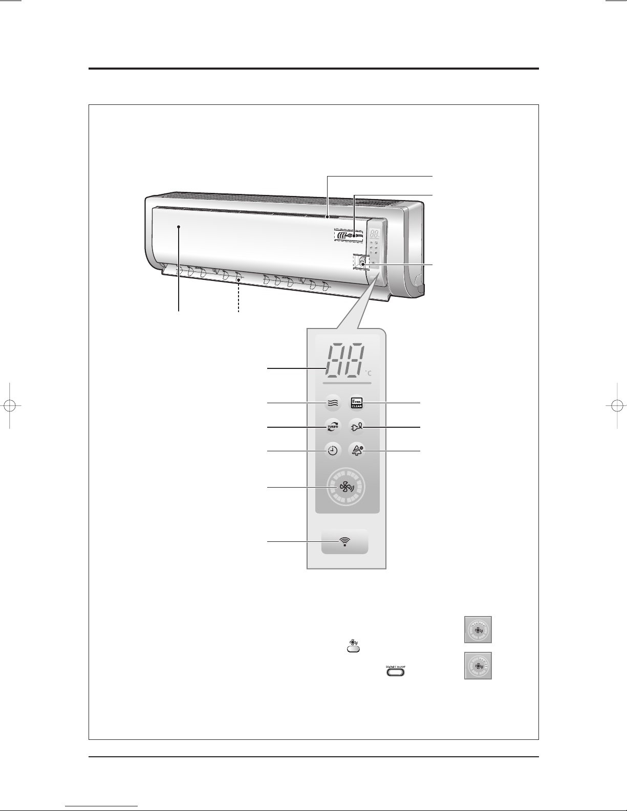
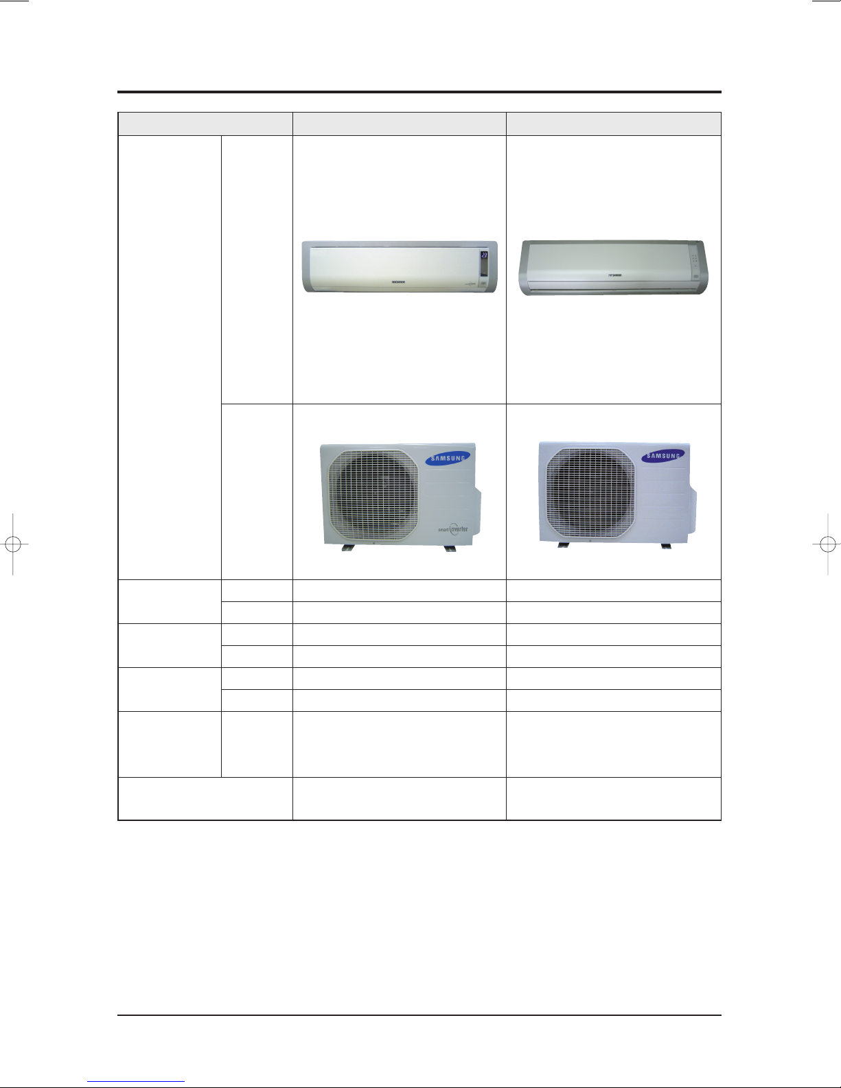
2-2 Name of Each Part
2-2-1 Indoor Unit
The design and shape can be changed according to the model.
Air Inlet
Room Temperature sensor
Power(On/Off) button
Air filter
(under the grille)
(Auto-Cool, Cool, Dry, Fan : Blue
Air flow blades
(outlet)
Set temperature &
room temperature
Operation indicator
Auto-Heat, Heat : Orange)
Turbo function indicator
Timer indicator
Fan speed indicator
Remote control sensor
(Blue)
(Orange)
(Blue)
Auto cleaning indicator
(Blue)
Energy saving indicator
(Blue)
Anions indicator
(Blue)
Note : • In the Auto mode, 2 fan indicators increase and decrease continuously and turn round.
• In the modes except the Auto mode, the fan speed indicator increases and decreases
continuously and turn round each time you press the button. If you set the Turbo
function, the fan speed indicator turns round with the maximum setting and speed.
• If you want to turn on/off the Display during operation, press the button on
the remote control.
• The room temperature sensor senses air temperature around the
sensor, and shows the temperature on the display.
Samsung Electronics2-2
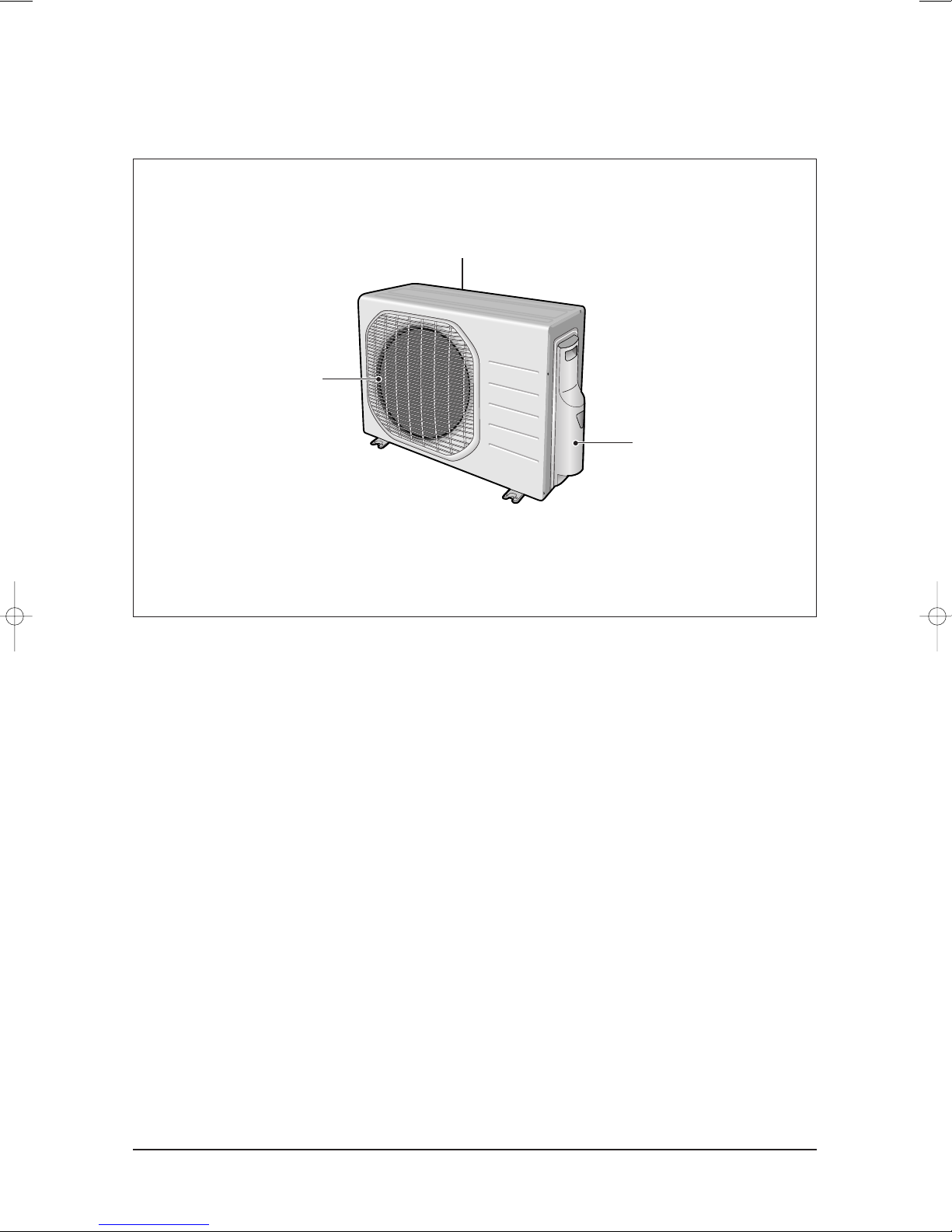
2-2-2 Outdoor Unit
Product Specifications
Air Inlet(Rear)
Air Outlet
Connection Valve
(inside)
2-3Samsung Electronics
2-3 Product Specifications
α
α
Item
Type
Cooling kW
Heating kW
Dehumidifying |/h
Air Volume
Performance
Noise
Energy Efficiency Ratio
Power ph-V-Hz
Power Consumption
Operating Current
Power
Power Factor
Power Cord Number of Core Wire
Outer Dimension
Weight(Net) kg
Refrigerant Pipe
Drain Hose DxL(mm)
Size
Compressor Motor Type
Oil Type
Blower Motor Type
Heat Exchanger
Refrigerant Control Unit
Freezer Oil Capacity cc
Refrigerant to Change(R410A) g
Protection Device(OLP)
Cooling Test Condition
Maximum Operation Condition
Type
Type
Cooling
Heating
Cooling
Heating
Cooling
Heating
Cooling
Heating
Cooling
Heating
Cooling
Heating
Length m
Capacity A
WidthxHeight
xDepth
Liquid mmxL(m)
Gas mmxL(m)
Rated Output
Rated Output W
Model
3
m
/min
(H/M/L)
dB
(H/L)
W/W
W
A
%
mm
inch
AS09BPA AS12BPA
Indoor unit Outdoor unit
Wall-mounted
0.99/2.5/3.5
0.85/3.5/5.0
1.25
7.8/6.1/4.5 31.5/13.0
8.2/6.5/4.9 31.5/13.0
40/25 51
40/25 51
4.13/4.1/3.4
3.86/3.9/3.36
1-220/240-50
240/610/1,030
220/900/1,490
1.5/3.0/5.0
1.35/4.4/6.85
91.0
92.0
2
3
15
950x268x165 790x548x285
37.4x10.6x6.5 31.1x21.6x11.2
940
ø6.35x7.5
ø9.52x7.5
ø18x550
Rotary, G4C090LU2ER
Hermetic
853W
FREOL 68ES-T
Cross-flow Propeller
Resin/Steel Resin/Steel
27 50
2Row 12Step 2Row 24Step
Expansion Valve
320
1,000
None
INDOOR UNIT : DB27˚C WB19˚C OUTDOOR UNIT : DB35˚C WB24˚C
INDOOR UNIT : DB32˚C WB23˚C OUTDOOR UNIT : DB43˚C WB26˚C
Indoor unit Outdoor unit
Wall-mounted
0.99/3.5/4.2
0.85/4.0/5.5
1.7
8.2/ 6.7/4.5 31.5/13.0
8.6/ 7.1/4.9 31.5/13.0
41/25 53
41/25 53
4.13/3.4/2.9
3.86/3.61/3.07
1-220/240-50
240/1,030/1,450
220/1,105/1,790
1.5/5.0/6.9
1.35/5.3/8.5
92.5
92.5
2
3
15
950x268x165 790x548x285
37.4x10.6x6.5 31.1x21.6x11.2
940
ø6.35x7.5
ø9.52x7.5
ø18x550
Rotary, G4C090LU2ER
Hermetic
853W
FREOL 68ES-T
Cross-flow Propeller
Resin/Steel Resin/Steel
27 50
2Row 12Step 2Row 24Step
Expansion Valve
320
1,000
None
Samsung Electronics2-4
2-4 The Comparative Specifications of Product
Design
Item
AS09BPA AS09HPB
Indoor
Unit
Outdoor
Unit
Net Weight
Outer Dimension
(WidthxHeightxDepth)
Noise
Air Purifying System Filter
Indoor Display
Indoor Unit
Outdoor Unit
Indoor Unit
Outdoor Unit
Indoor Unit
Outdoor Unit
9.0kg
40.0kg
950x268x165mm
790x548x285mm
40dB↓
51dB↓
Silver Nano Metallic Filter
Anti-Allergy Filter
Deodorizing Filter
ach
Det
able Display
Rotatio
ue LED Display
n Bl
9.0kg
33.8kg
950x268x165mm
790x548x285mm
40dB↓
51dB↓
Silver Nano Metallic Filter
Anti-Allergy Filter
Deodorizing Filter
ach
Det
able Display
Rotatio
ue LED Display
n Bl
2-5Samsung Electronics

The Comparative Specifications of Product(cont.)
Design
Item
AS12BPA AS12HPB
Indoor
Unit
Outdoor
Unit
Net Weight
Outer Dimension
(WidthxHeightxDepth)
Noise
Air Purifying System Filter
Indoor Display
Indoor Unit
Outdoor Unit
Indoor Unit
Outdoor Unit
Indoor Unit
Outdoor Unit
9.0kg
40.0kg
950x268x165mm
790x548x285mm
41dB↓
53dB↓
Silver Nano Metallic Filter
Anti-Allergy Filter
Deodorizing Filter
ach
Det
able Display
Rotatio
ue LED Display
n Bl
9.0kg
36.0kg
950x268x165mm
790x548x285mm
43dB↓
53dB↓
Silver Nano Metallic Filter
Anti-Allergy Filter
Deodorizing Filter
ach
Det
able Display
Rotatio
ue LED Display
n Bl
Samsung Electronics2-6
2-5 Accessory and Option Specifications
O
W
N
E
R
'
S
I
N
S
T
R
U
C
T
I
O
N
S
M
A
N
U
A
L
D
E
I
N
S
T
R
U
C
C
I
O
N
E
S
I
S
T
R
U
Z
I
O
N
I
P
E
R
L
'
U
S
O
M
A
N
U
A
L
D
E
I
N
S
T
R
U
Ç
Õ
E
S
M
A
N
U
E
L
D
'
U
T
I
L
I
S
A
T
I
O
N
G
E
B
R
A
U
C
H
S
A
N
W
E
I
S
U
N
G
S
p
l
u
t
-
t
y
p
e
R
o
o
m
A
i
r
C
o
n
d
i
t
i
o
n
e
r
A
i
r
e
a
c
o
n
d
i
c
i
o
n
a
d
o
d
o
m
é
s
t
i
c
o
s
i
s
t
e
m
a
S
p
l
i
t
C
o
n
d
i
z
i
o
n
a
t
o
r
e
d
'
a
r
i
a
p
e
r
a
m
b
i
e
n
t
i
a
d
u
n
i
t
à
S
e
p
a
r
a
t
e
A
p
a
r
e
l
h
o
d
e
a
r
c
o
n
d
i
c
i
o
n
a
d
o
t
i
p
o
S
p
l
i
t
C
l
i
m
a
t
i
s
e
u
r
d
e
t
y
p
e
s
é
p
a
r
é
G
e
t
e
i
l
t
e
r
a
u
m
k
l
i
m
a
a
n
l
a
g
e
O
W
N
E
R
'
S
I
N
S
T
R
U
C
T
I
O
N
S
M
A
N
U
A
L
D
E
I
N
S
T
R
U
C
C
I
O
N
E
S
I
S
T
R
U
Z
I
O
N
I
P
E
R
L
'
U
S
O
M
A
N
U
A
L
D
E
I
N
S
T
R
U
Ç
Õ
E
S
M
A
N
U
E
L
D
'
U
T
I
L
I
S
A
T
I
O
N
G
E
B
R
A
U
C
H
S
A
N
W
E
I
S
U
N
G
S
p
l
u
t
-
t
y
p
e
R
o
o
m
A
i
r
C
o
n
d
i
t
i
o
n
e
r
A
i
r
e
a
c
o
n
d
i
c
i
o
n
a
d
o
d
o
m
é
s
t
i
c
o
s
i
s
t
e
m
a
S
p
l
i
t
C
o
n
d
i
z
i
o
n
a
t
o
r
e
d
'
a
r
i
a
p
e
r
a
m
b
i
e
n
t
i
a
d
u
n
i
t
à
S
e
p
a
r
a
t
e
A
p
a
r
e
l
h
o
d
e
a
r
c
o
n
d
i
c
i
o
n
a
d
o
t
i
p
o
S
p
l
i
t
C
l
i
m
a
t
i
s
e
u
r
d
e
t
y
p
e
s
é
p
a
r
é
G
e
t
e
i
l
t
e
r
a
u
m
k
l
i
m
a
a
n
l
a
g
e
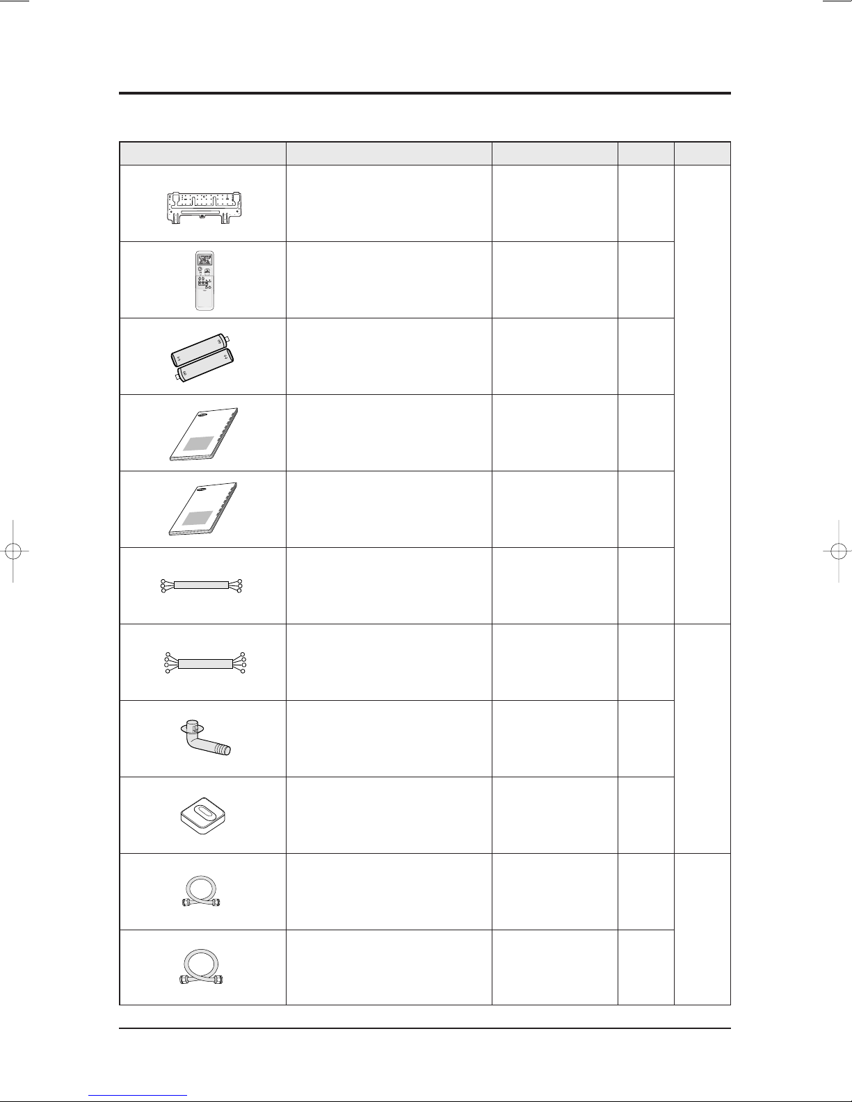
2-5-1 Accessories
Item Descriptions Q'TYCode-No. Remark
Installation Plate DB70-00514A 1
Remote Control DB93-03016R 1
Batteries for Remote Control DB47-90024A 2
User's Manual DB98-23940A 1
Indoor
Unit
Installation Manual DB98-23975A 1
3-wire Power Cable DB93-01549C 1
4-wire Assembly Cable - 1
Drain Plug DB67-20011A 1
Rubber Leg DB73-00179A 4
Assembly Pipe, ø6.35mm DB96-10453B 1
Outdoor
Unit
Accessory
Box
Assembly Pipe, ø9.52mm DB96-10453F 1
2-7Samsung Electronics
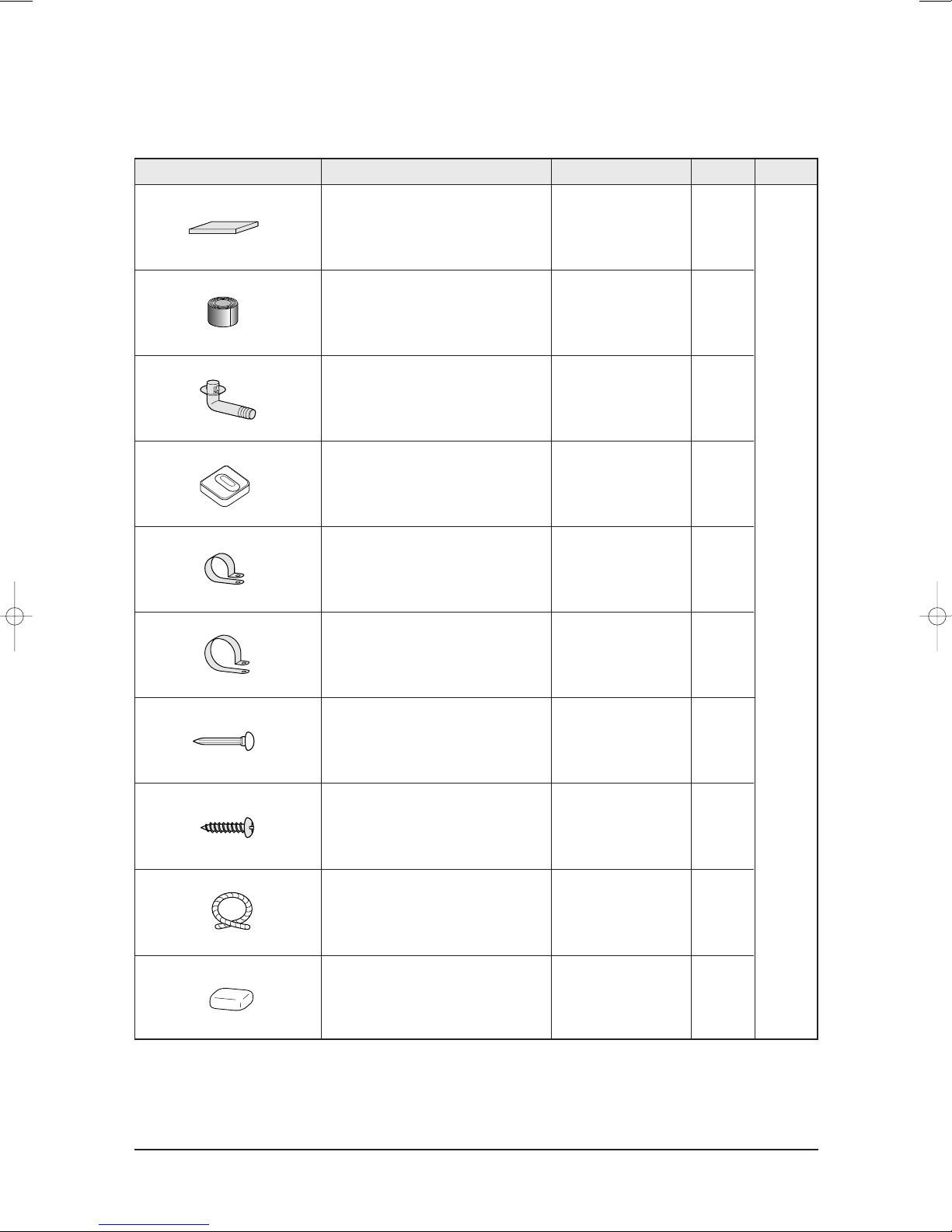
Product Specifications
Accessories(cont.)
Item Descriptions Q'TYCode-No. Remark
PE T3 Foam Tube Insulation DB72-50165A 1
Vinyl Tape, Width 50mm DB72-00459A 1
Drain Plug DB67-20011A 1
Rubber Leg DB73-00179A 4
Accessory
Box
Pipe Clamps A DB39-20224A 3
Pipe Clamps B DB39-20224B 3
Cement Nail - 6
M4x16 Tapping Screws 6002-000215 10
Drain Hose, length 2m DB62-00487A 1
Putty 100g DB98-10568A 1
Samsung Electronics2-8
3. Alignment and Adjustments
3-1 Indoor Display Error and Check Method
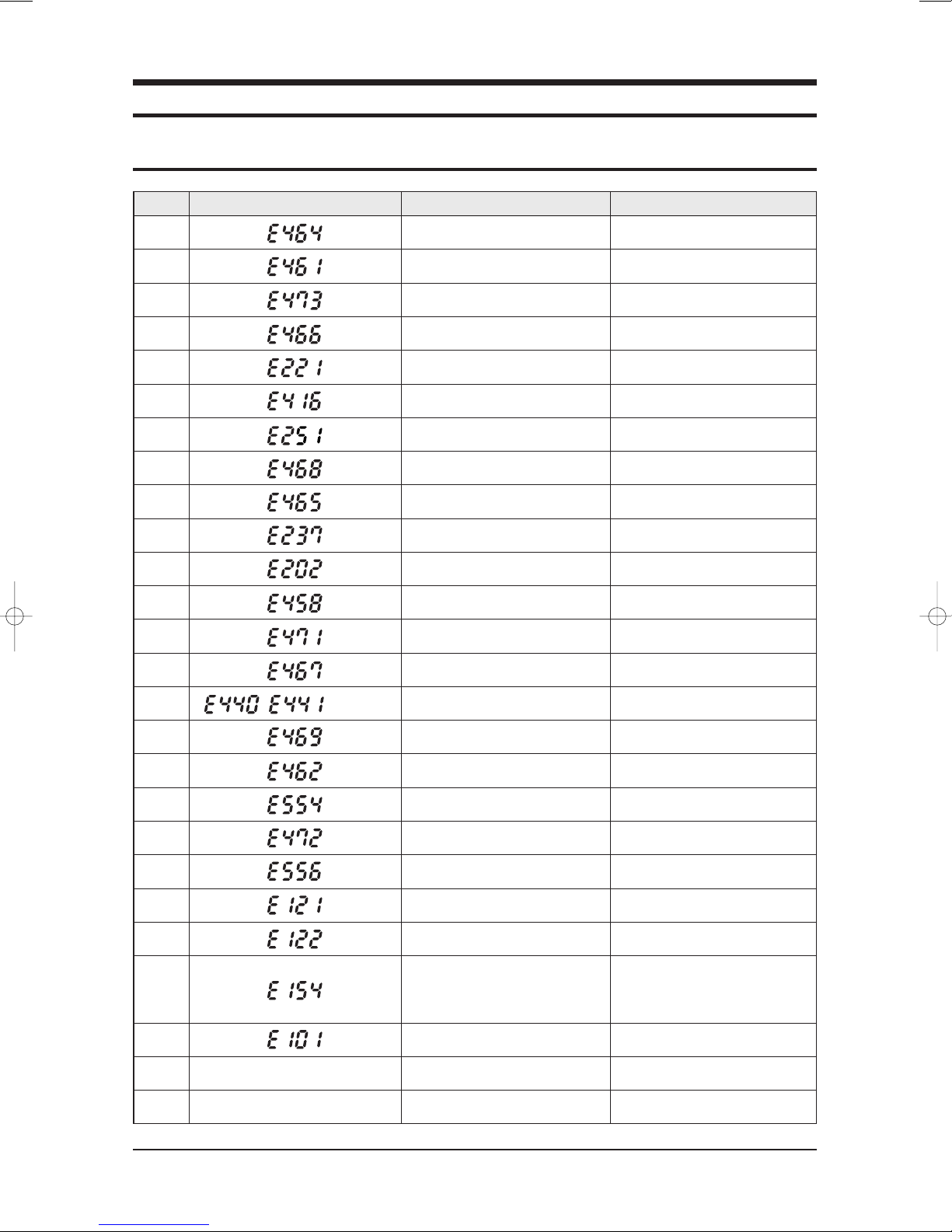
LED DisplayNo Explanation Explanation
1 IPM Over Current(O.C)
2 Compressor Starting Error
3 Compressor Lock Error
4 DC-Link voltage under/over Error
5 Outdoor temperature sensor Error
6 Discharge over temperature
7 Discharge temperature sensor Error
8 Current sensor Error
9 Compressor Vlimit Error
10 Coil temperature sensor Error
11 1min. Time out Communication
12 Fan Error
13 OTP Error
14 Compressor Rotation Error
15 (Low/High) Operation condition secession
16 DC-Link valtage sensor Error
17 I_Trip error / PFC Over current
18 Gas Leak Error
19 AC Line Zero Cross Signal out
20 Capacity Miss-match
21 Room sensor Error Open/Short
22 In-coil sensor Error Open/Short
23 FAN Error
/
Indoor Fan Motor Abnormal Operation
Holding for 15 sec. at less than 450rpm
24 1min. Time out Communication
25 All Lamps Blink EEPROM Error
26 All Lamps Blink Option Error Option Not Set up, Option Data Error
3-1Samsung Electronics

3-2 Outdoor LED Error Display and Check Method
No
Yellow Green Red
1 Power off/VDD NG
2 IPM Over Current(O.C)
3 Abnormal Serial communication
4 Compressor Starting error
5 Normal Operation
6 Compressor Lock error
7 DC-Link voltage under/over error
8 Outdoor temperature sensor error(Dual/Single)
9 Discharge over temperature(Dual/Single)
10 Discharge temperature sensor error(Dual/Single)
11 Current sensor error
12 Compressor Limit error
LED Display
Explanation
13 Coil temperature sensor error(Dual/Single)
14 1min. Time out Communication
15 Fan error
16 OTP error
17 Compressor rotation error
18 Operation condition secession(Dual only)
19 DC-Link voltage sensor error
20 I_Trip error / PFC Over current
21 GAS Leak error(Dual/Single)
22 AC Line Zero Cross Signal out
23 Power ON reset(1sec)
24 Capacity miss match
25 Test Operation at Cooling Mode
26 Test Operation at Heating Mode
: LED ON, : LED OFF, : LED BLINK
Samsung Electronics3-2
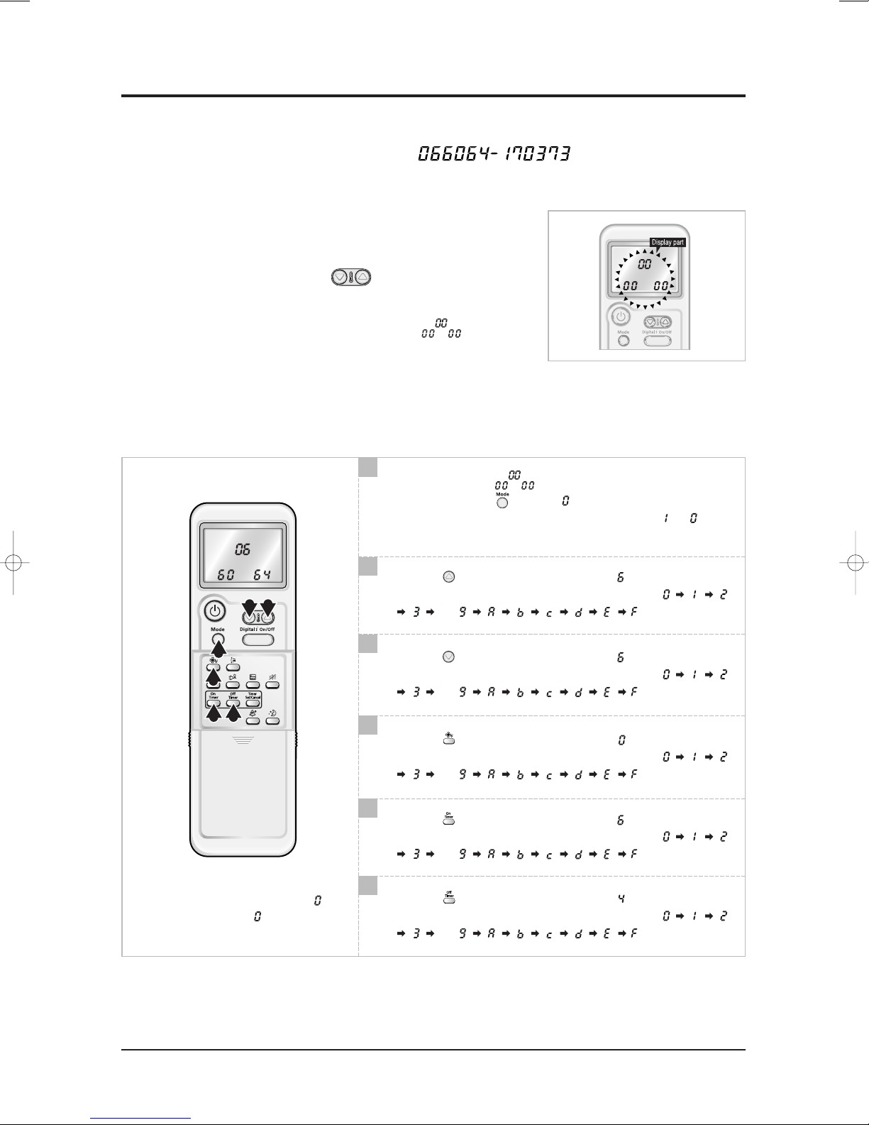
3-3 Setting Option Setup Method
ex) Option No. :
Step 1 : Enter the Option Setup mode.
st
1
2
3
Step 2 : Enter the Option Setup mode and select your option according to the following procedure.
Take out the batteries of remote control.
nd
Press the temperature button simultaneously and
insert the battery again.
rd
Make sure the remocon display shown as .
1
The default value is .
Otherwise, push the button to .
Every time you push the button, the display panel reads or
repeatedly.
3 2
1
4
5 6
✳ Setting is not required if you must
a value which has a default.
2
Push the button to set the display panel to .
Every time you push the button, the display panel reads
. . .
3
Push the button to set the display panel to .
Every time you push the button, the display panel reads
. . .
4
Push the button to set the display panel to .
Every time you push the button, the display panel reads
. . .
5
Push the button to set the display panel to .
Every time you push the button, the display panel reads
. . .
6
Push the button to set the display panel to .
Every time you push the button, the display panel reads
. . .
repeatedly.
repeatedly.
repeatedly.
repeatedly.
repeatedly.
3-3Samsung Electronics
Alignment and Adjustments
9 8
7
10
11 12
7
Press button, then the default value is .
8
Push the button to set the display panel to .
Every time you push the button, the display panel reads
. . .
9
Push the button to set the display panel to .
Every time you push the button, the display panel reads
. . .
10
Push the button to set the display panel to .
Every time you push the button, the display panel reads
. . .
11
Push the button to set the display panel to .
Every time you push the button, the display panel reads
. . .
repeatedly.
repeatedly.
repeatedly.
repeatedly.
12
Push the button to set the display panel to .
✳ Setting is not required if you must
a value which has a default.
Step 3 : Upon completion of the selection, check you made right selections.
Press the Mode Selection key, to set the display part to and check the display part.
The display part shows .
Press the Mode Selection key, to set the display part to and check the display part.
The display part shows .
Step 4 : Pressing the ON/OFF button ( )
When pressing the operation ON/OFF key with the direction of remote control for unit, the sound ''Ding'' or ''Diriring''
is heard and the OPERATION ICON( ) lamp of the display is flickering at the same time, then the input of option is
completed. (If the diriring sound isn't heard, try again pressing the ON/OFF button.)
Step 5 : Unit operation test-run
First, Remove the battery from the remote control.
Second, Re-insert the battery into the remote control.
Third, Press ON/OFF key with the direction of remote control for set.
Every time you push the button, the display panel reads
. . .
repeatedly.
• Error Mode
st
1
If all lamps of indoor unit are flickering, plug out, plug in power plug again and press the ON/OFF key to retry.
nd
If the unit is not working properly or all lamps are continuously flickering after setting the option code, see if the correct option code
2
is set up for its model.
Samsung Electronics3-4
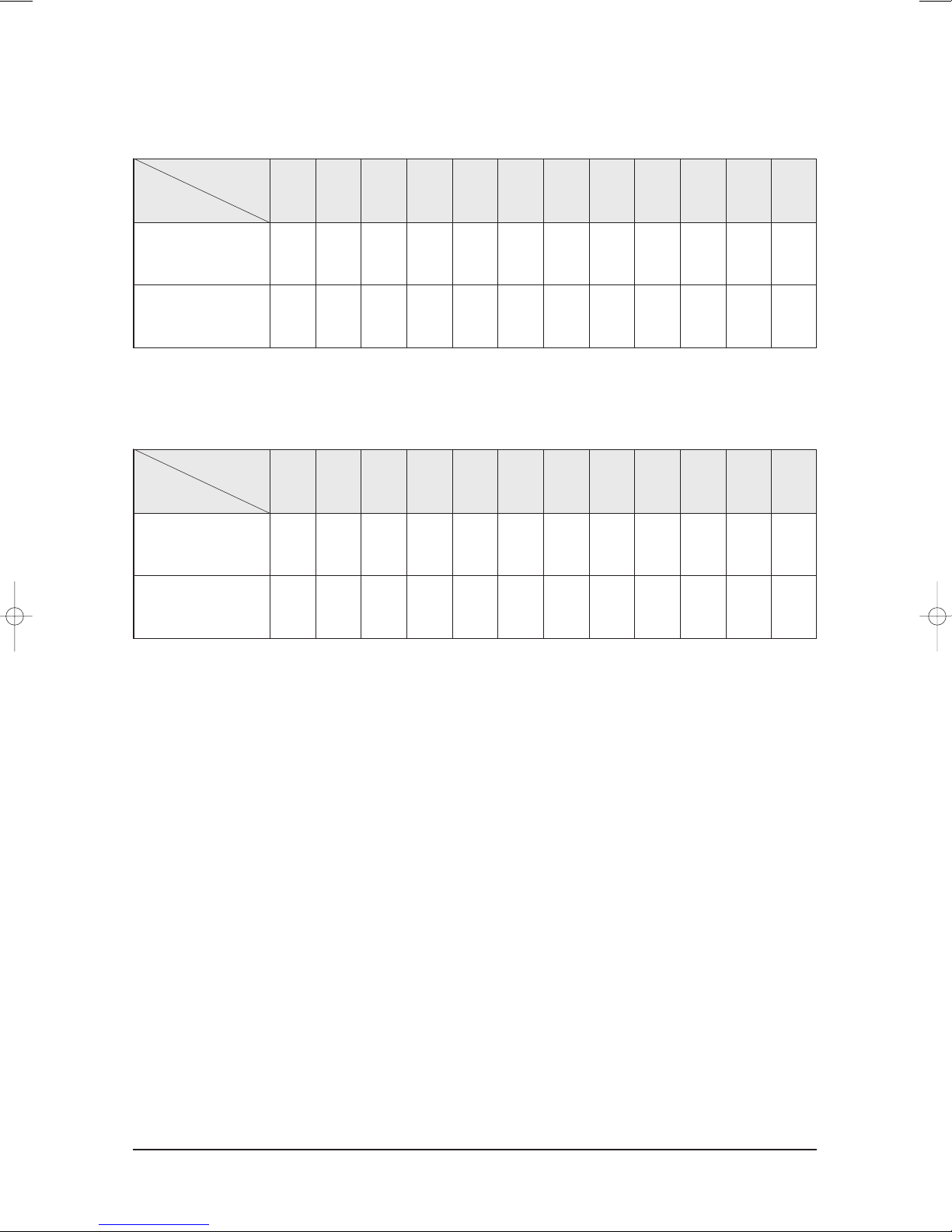
■ OPTION ITEMS
REMOCON
MODEL
Alignment and Adjustments
SEG1 SEG2 SEG3 SEG4 SEG5 SEG6 SEG7 SEG8 SEG9 SEG10 SEG11 SEG12
AS09BPAN
AS12BPAN
00A777175247
014677175267
✳ For Australia, exceptionally
REMOCON
MODEL
AS09BPAN/XSA
AS12BPAN/XSA
SEG1 SEG2 SEG3 SEG4 SEG5 SEG6 SEG7 SEG8 SEG9 SEG10 SEG11 SEG12
00A577175247
014577175267
3-5Samsung Electronics
4. Disassembly and Reassembly
Stop operation of the air conditioner and remove the power cord before repairing the unit.
4-1 Indoor Unit
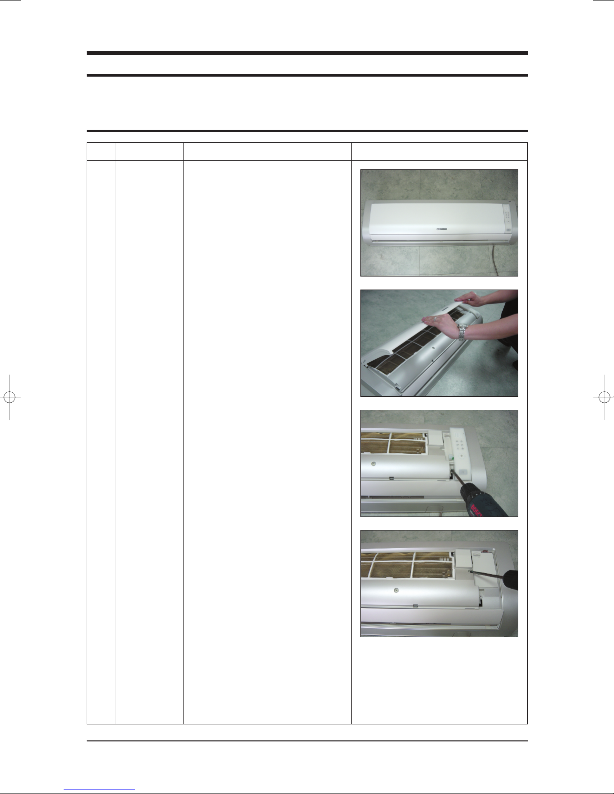
No Parts Procedure Remark
1 Panel Front
1) Stop the air conditioner operation and
shut off the main power.
2) Detach the Front Grille after pushing
out it.
3) Loosen 1 of the right screw and detach
the Ass'y display.
4) Loosen 1 of the right screw and detach
the Terminal Cover.
5) Detach the cover PCB-DVM and thermistor from the Panel Front.
Samsung Electronics4-1

Disassembly and Reassembly
No Parts Procedure Remark
6) Loosen 5 fixing screws of Panel Front.
7) Unlock 2 hooks to fix Panel Front and
Tray Drain.
8) Unlock 2 hooks to fix Panel Front and
Back Body.
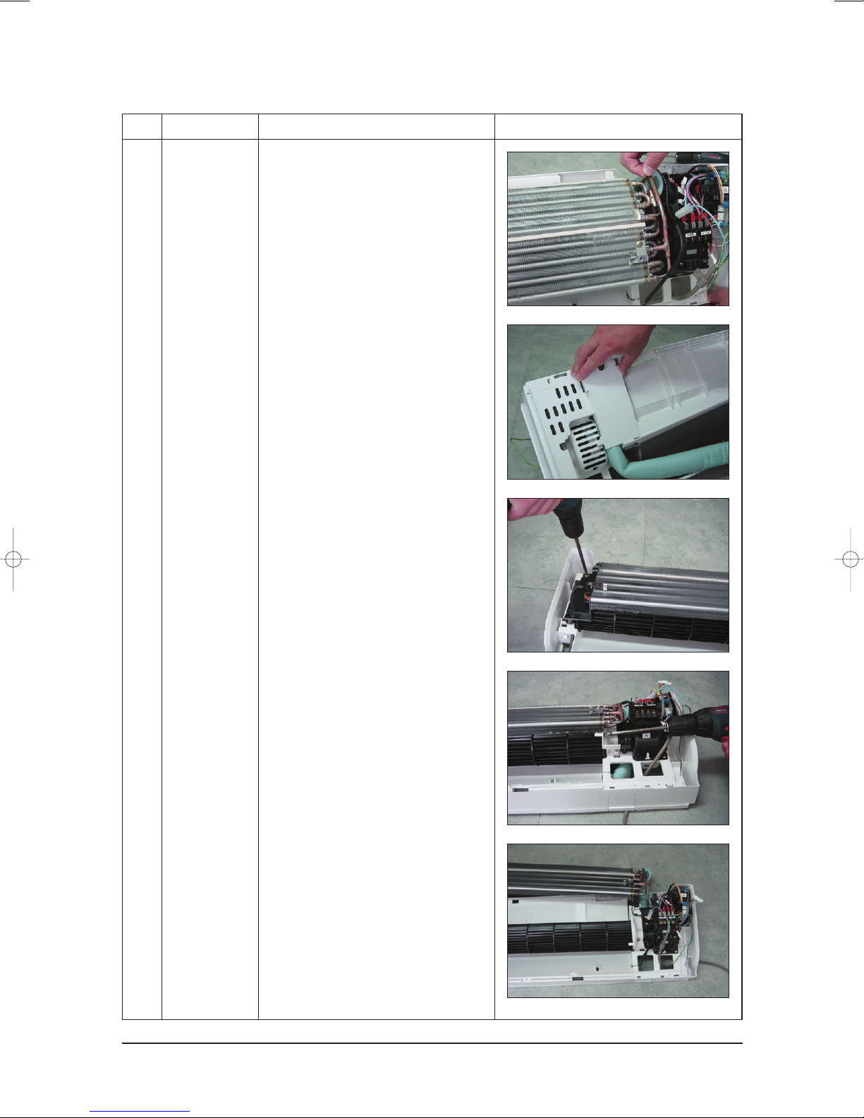
2
3
Heat Exchanger
Tray Drain
1) Detach the connected wire of Stepping
Motor.
2) Pull Tray Drain out from the Back Body.
1) Loosen 1 fixing earth screw of right side.
4-2Samsung Electronics
Disassembly and Reassembly
No Parts Procedure Remark
2) Detach the Room Sensor.
3) Detach the Holder Pipe at the rear side
of the unit.
4) Loosen 3 fixing screws of left Holder
Evap.
5) Loosen 1 fixing screw of right Holder
Motor.
6) Detach the Heat Exchanger from the
indoor unit.
Samsung Electronics4-3
Disassembly and Reassembly
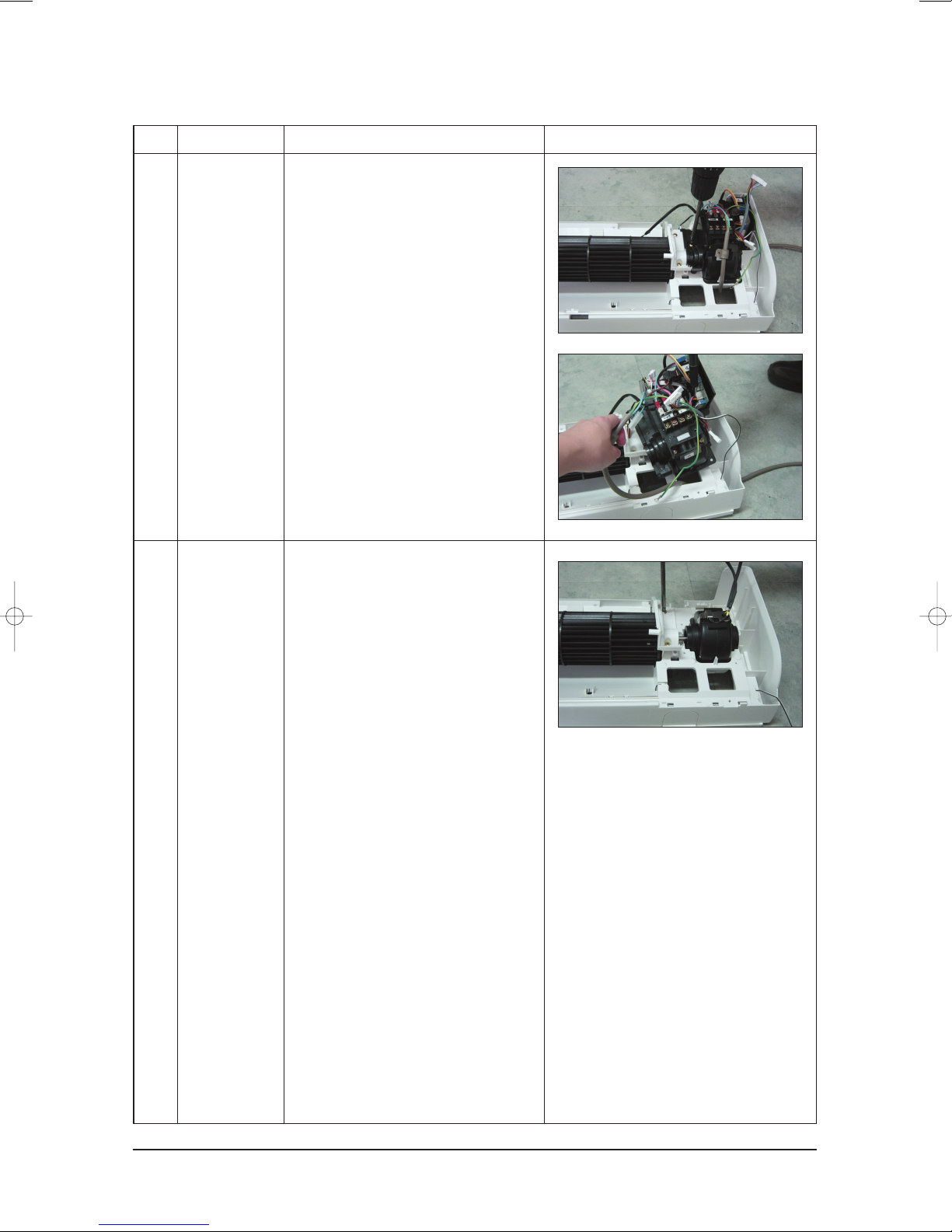
No Parts Procedure Remark
4
5
Electrical Parts
(Main PCB)
Fan Motor
&
Cross Fan
1) Loosen 4 fixing screws of right Holder
control.
2) Take all the connector of PCB upper side
out.(Including Power Cord)
3) Detach the outdoor unit connection wire
from the Terminal Block.
4) Pull the PCB up to detach.
1) Loosen 2 fixing screws and detach the
Motor Holder.
2) Loosen 1 fixing screw of Fan Motor.
3) Detach the Fan Motor from the Fan.
4) Detach the Fan from the left Holder
Bearing.
4-4Samsung Electronics
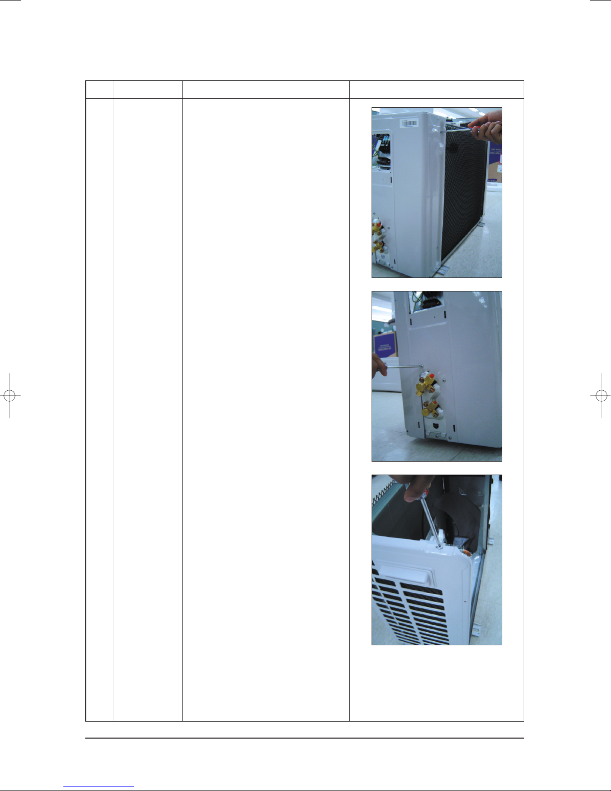
4-2 Outdoor Unit
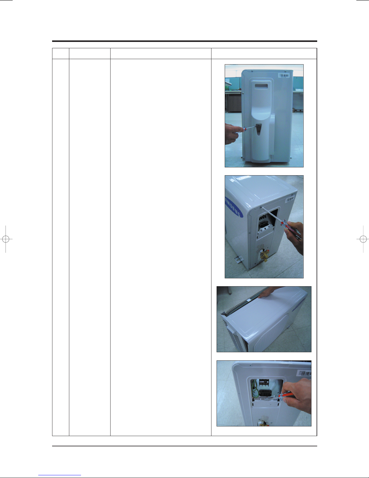
No Parts Procedure Remark
1 Common Work
1) Loosen 1 fixing screw of the Cover-Side.
2) Loosen each 3 fixing screws on both
right and left Cabinet Side edges and
a fixing screw on the Cabinet Front lower
to detach the Cabinet Front.
3) Detach the Cabinet Front like the picture
on the right side.
4) Loosen 1 screw fixed to assemble
Plate Control Out with Cabinet-Side RH.
Samsung Electronics4-5
Disassembly and Reassembly
No Parts Procedure Remark
5) Loosen 2 fixing screws on the rear side
of Cabinet-Side RH.
6) Loosen 3 screws fixed to assemble
Bracket Valve with Cabinet-Side RH.
7) Loosen 2 fixing screws of Cabinet-Side LF.
4-6Samsung Electronics
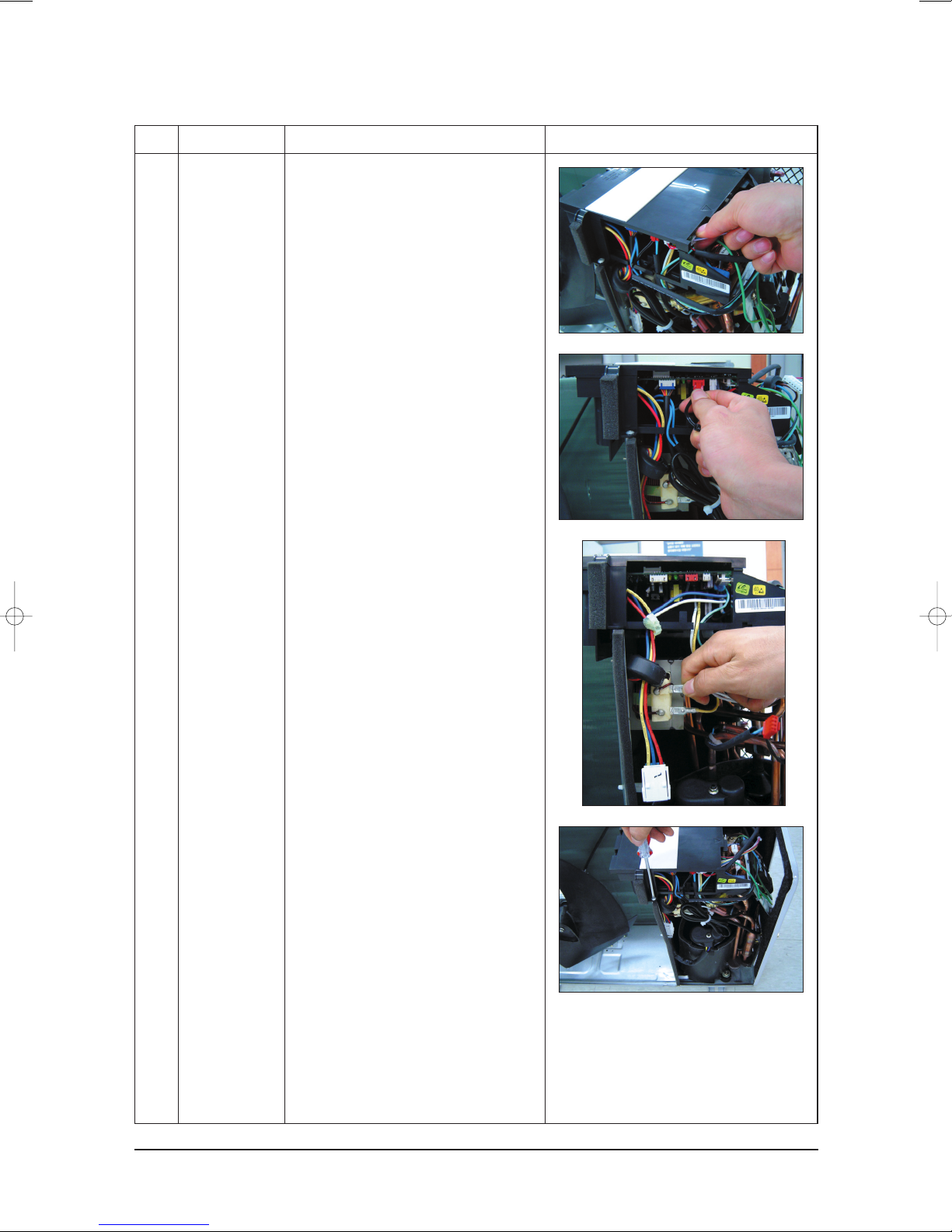
Disassembly and Reassembly
No Parts Procedure Remark
2 Ass'y Control
Out
1) Detach the Motor Wire from the PCB of
Ass'y Control Out.
2) Detach several connectors from the PCB
of Ass'y Control Out.
3) Detach 2 Connect Wires from Reactor.
4) Loosen 1 screw fixed to assemble
Ass'y Control Out with Partition.
Samsung Electronics4-7
Disassembly and Reassembly
No Parts Procedure Remark
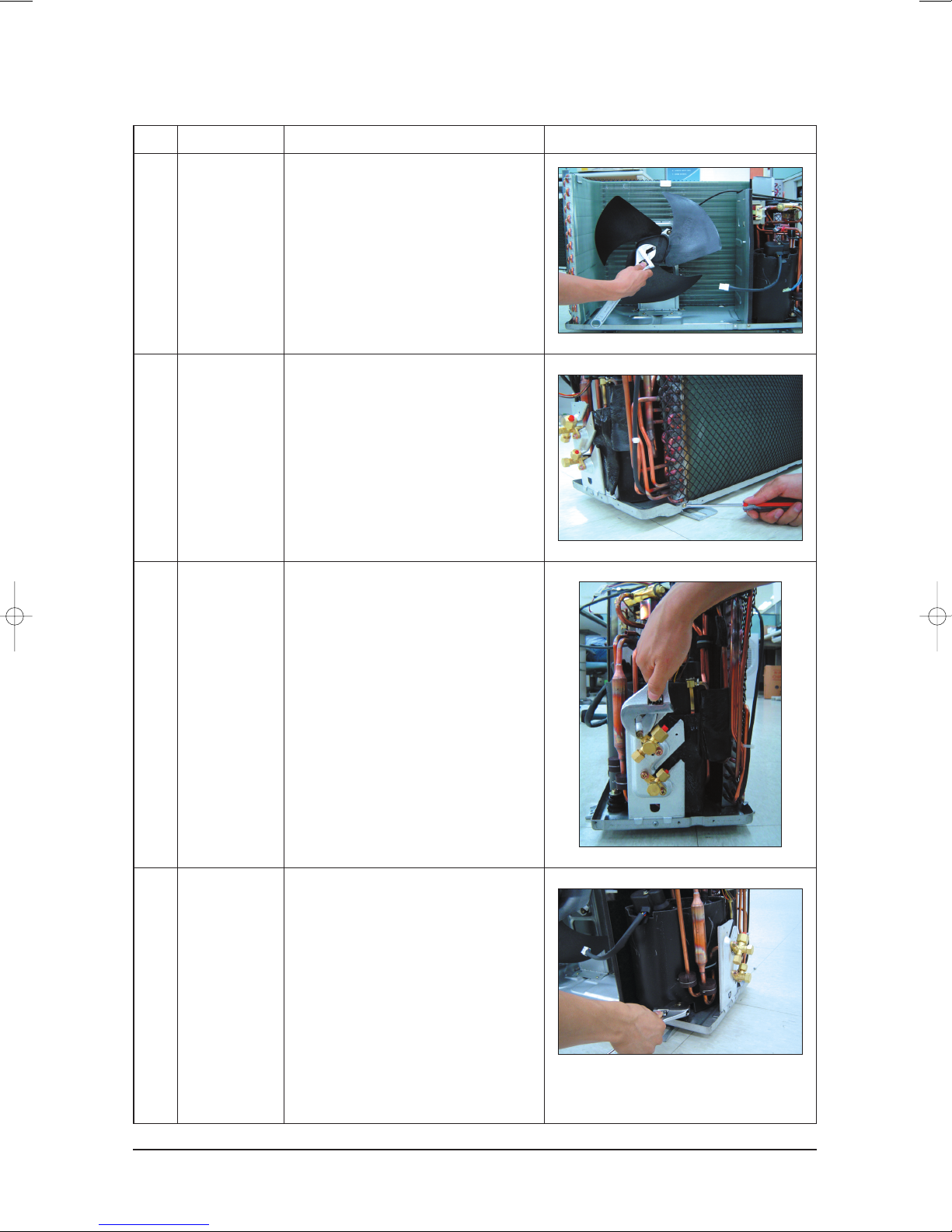
3
Heat Exchanger
4
Ass'y Valve 4-Way
5
Ass'y Valve EEV
Fan
&
Motor
&
1) Detach the Nut Flange like the picture
on the right side. (Turn counterclockwise
because the screw is right-handed.)
2) Detach the Fan Propeller.
3) Loosen 4 fixing screws to detach the
Motor.
1) Loosen 2 fixing screws on both sides.
2) Disassemble the pipes in both inlet and
outlet with welding torch.
3) Detach the Heat Exchanger.
1) Loosen 4 bolts fixed to assemble Valve
Service with Bracket Valve like the picture
on the right side.
2) Disassemble the pipes assembled the
suction and discharge sides of the
Compressor with welding torch.
6
Compressor
1) Loosen the Nut of Terminal Cover.
2) Detach the Terminal Cover and detach
the Connect Comp Wire from
Compressor.
3) Disassemble the Felt Comp Sound.
4) Loosen the 3 bolts at the bottom of
Compressor like the picture on the
right side.
4-8Samsung Electronics
10
12
16
11
5
13
19
21
22
15
7
23
23-1
3
6
17
14
1
18
9
4
8
24
14-6
14-1
1-1
1-2
9-2
9-3
2-5
23-2
3-2
3-4
3-1
3-3
2-1
2-6
2-5-1
2-4
2-2
2-3
9-1
14-5
14-2
14-3
14-4
20
2
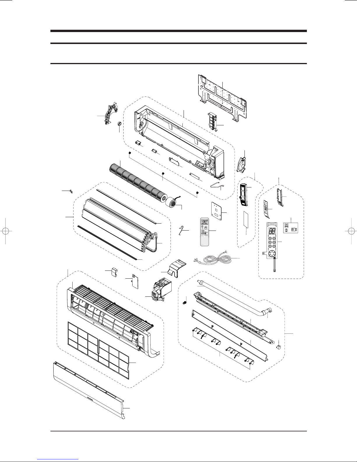
5. Exploded Views and Parts List
5-1 Indoor Unit
Samsung Electronics5-1
Exploded Views and Parts List
■
Parts List
No. Code No. Description Specification SA/SNA Remark
1 DB92-00633B ASS'Y PANEL FRONT ASS'Y 1 1 SA
1-1 DB64-01210B PANEL FRONT HIPS 1 1 SNA
1-2 DB63-01103A FILTER-PRE PP 1 1 SNA
2 DB94-00629A ASS'Y TRAY DRAIN ASS'Y 1 1 SA
2-1 DB63-01104A TRAY DRAIN ABS 1 1 SNA
2-2 DB61-02049A BLADE-H ABS 1 1 SA
2-3 DB61-02053A BLADE-V PP 2 2 SA
2-4 DB73-00234A RUBBER-CAP DRAIN CR 1 1 SNA
2-5 DB94-00062L ASS'Y DRAIN-HOSE ASS'Y 1 1 SA
2-5-1 DB67-00510A DRAIN-CUFF ABS 1 1 SNA
2-6 DB95-20138A ASS'Y MOTOR-STEPPING 24BYJ48 1 1 SA
3 DB93-02960A ASS'Y DISPLAY ASS'Y 1 1 SA
3-1 DB61-02056A HOLDER DISPLAY HIPS 1 1 SNA
3-2 DB64-01211A WINDOW DISPLAY HIPS 1 1 SNA
3-3 DB93-02806A ASS'Y PCB DISPLAY ASS'Y 1 1 SA
3-4 DB93-01369A ASS'Y MODULE PCB ASS'Y 1 1 SA
4 DB63-01106A COVER TERMINAL HIPS V0 1 1 SA
5 DB63-01107A COVER PCB-DVM HIPS 1 1 SA
6 DB61-02050A HOLDER EVAP ABS 1 1 SA
7 DB61-02052A HOLDER MOTOR PP 1 1 SA
8 DB93-03449A ASS'Y CONTROL IN ASS'Y 1 1 SA
9 DB96-03835C ASS'Y EVAP TOTAL ASS'Y 1 1 SA
9-1 DB60-00198A SPACER-EVAP MID PVC 1 1 SNA
9-2 DB60-00203B SPACER-EVAP UP PVC 1 1 SNA
9-3 DB96-03834C ASS'Y EVAP FP1.3, H-FIN, 2x12 1 1 SNA
10 DB67-60030A SPRING-SENSOR STS 304 1 1 SNA
11 DB94-00674A ASS'Y BEARING-RUBBER ASS'Y, CR 45 1 1 SA
12 DB94-00627A ASS'Y-CROSS FAN ø83x719 1 1 SA
13 DB31-00270A MOTOR FAN-IN YDK-20S4D8C-1 1 1 SA
14 DB94-00626A ASS'Y BACK BODY ASS'Y 1 1 SA
14-1 DB61-02057A BODY BACK HIPS 1 1 SNA
14-2 DB61-02047A BUSH BODY LF HIPS 1 1 SNA
14-3 DB61-02048A BUSH BODY RH HIPS 1 1 SNA
14-4 DB63-01105A COVER-IONIZER HIPS 1 1 SNA
14-5 DB91-00287A ASS'Y ELECTRIC-IONIZER ASS'Y 1 1 SNA
14-6 DB93-01383G ASS'Y C/W ION ASS'Y 1 1 SA
15 DB61-02051A HOLDER-PIPE HIPS 1 1 SNA
16 DB67-00508A CAP SCREW HIPS 3 3 SA
17 DB70-00514A PLATE-HANGER SGCC-M, T0.8 1 1 SA
18 DB70-00515A PLATE CONTACT SUS 304 1 1 SNA
19 DB70-00516A PLATE-CONTROL IN SGCC-M 1 1 SA
AS09BPAN AS12BPAN
Q'TY
Samsung Electronics 5-2
Exploded Views and Parts List
■
Parts List(cont.)
No. Code No. Description Specification SA/SNA Remark
20 DB93-01549C ASS'Y-CONNECTOR POWER ASS'Y 1 1 SA
21 DB93-03016R ASS'Y REMOCON ARH-1315 1 1 SA
22 DB92-00643G ASS'Y GRILLE ASS'Y 1 1 SA
23 DB90-01829A ASS'Y COVER DISPLAY ASS'Y 1 1 SA
23-1 DB63-01108A COVER DISPLAY PC 1 1 SNA
23-2 DB64-01276A INLAY DISPLAY ACRYL 1 1 SNA
24 DB63-01253A COVER CONTROL SGCC-M 1 1 SA
AS09BPAN AS12BPAN
Q'TY
Samsung Electronics5-3
 Loading...