

Samsung AS07A5MA, AS12ABMCF, US07A5MA, AS07A6MA, US07A6MA Service Manual
...
Manual
SERVICE
SPLIT TYPE AIR CONDITIONER
Indoor Unit
AS07A5(6)MA
AS09A5(6)MAF
AS12AA(B)MCF
Outdoor Unit
US07A5(6)MA
US09A5(6)MAF
US12AA(B)MCF
E DB98-15774A(1)


Safety Precautions
The following safety precautions must be taken when using your air conditioner.
WARNING
I
NSTALLING THE UNIT
POWER SUPPLY LINE,
FUSE OR CIRCUIT
BREAKER
Risk of electric shock. • Can cause injury or death. • Disconnect all remote electric
power supplies before servicing, installing or cleaning. • This must be done by the
manufacturer or its service agent or a similar qualified person in order to avoid a
hazard.
◆ The unit should not be installed by the user. Ask the dealer or authorized
company to install the units except room air conditioners for the U.S.A and
Canada area.
◆ If the unit is installed improperly, water leakage, electric shock or fire may
result.
◆ The air conditioner must be installed in accordance with national wiring
regulations and safety regulations wherever applicable.
◆ Mount with the lowest moving parts at least 8.2ft(2.5m) above the floor or
grade level. (If applicable)
◆ The manufacturer does not assume responsibility for accidents or injury
caused by an incorrectly installed air conditioner. If you are unsure about
installation, contact an installation specialist.
◆ When installing the built-in type air conditioner, keep all electrical cables
such as the power cable and the connection cord in pipe, ducts, cable
channels e.t.c to protect them against liquids, outside impacts and so on.
◆ If the power cord of this air conditioner is damaged, it must be replaced by
the manufacturer, its service agent or similarly qualified persons in order to
avoid a hazard.
◆ The unit must be plugged into an independent circuit if applicable or
connect the power cable to the auxiliary circuit breaker. An all pole
disconnection from the power supply must be incorporated in the fixed
wiring with a contact opening of >3mm.
◆ Do not use an extension cord with this product.
◆ If the unit is equipped with a power supply cord and a plug, the plug must
be accessible after installation.
◆ This appliance must be installed accordance with the national wiring
regulations.
2
Contents
ΙΙ
DISASSEMBLE AND REASSEMBLE
1. Indoor unit
2. Outdoor unit
ΙΙΙΙ
ET UP THE OPTION CODE 10
S
ΙΙΙΙΙΙ
TROUBLESHOOTING
1. Items to be checked first
2. Abnormal diagnosis by symptom
ΙΙΛΛ
ASSEMBLY DRAWING AND PART’S LIST
1. Indoor unit
2. Outdoor unit
3. Assembly control in
4. Assembly control out
ΛΛ
REFRIGERATING CYCLE BLOCK DIAGRAM 31
ΛΛ
ΙΙ
PERFORMANCE CURVE 32
4
6
13
14
22
24
28
29
ΙΙΙΙ
ΛΛ
WIRING DIAGRAMS
1. Indoor unit
2. Outdoor unit
ΛΛΙΙΙΙΙΙ
S
CHEMATIC
1. Indoor unit
2. Outdoor unit
DIAGRAMS
SPLIT TYPE
AIR CONDITIONER
41
42
44
45
3

ΙΙ
Disassemble and reassemble
Stop operation of the air conditioner and remove the power cable before repairing the unit.
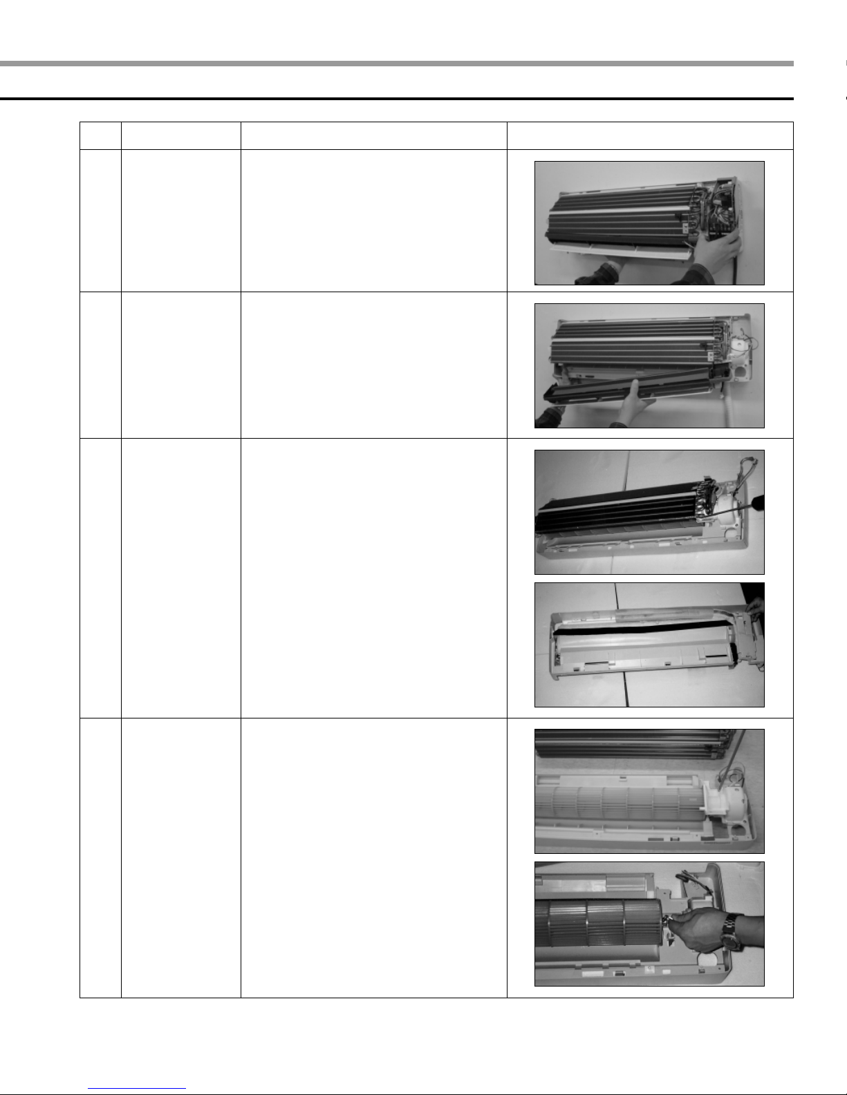
1 Indoor unit
If you disassemble the heat exchanger, you must pump down at first.
No. Part Procedure Remark
1
Front Panel
1) Stop the operation of the air conditioner
and block the main power.
2)Separate the tape from the front panel.
3)Contract the second finger to the left,
and right handle. And pull the inlet grille
to open.
4)Take the left and right filter out.
*Taking off the deodorizing filter.
5)Loosen one of the right screw and
separate the terminal cover.
6)Loosen three screws of front panel.
7)Pull the upper left, center and right of
discharge softly so that the outside
cover is pulled out.
8)Pull softly the lower part of discharge and
push it up.
Caution
Assemble the front panel and fix the
hooks of left, center and right.
4
No.
Part
Procedure Remark
2
3
4
Electrical
Parts
(Main PCB)
Assembly Tray
Drain
Heat
Exchanger
1) Take all the connector of PCB
on the upper part. (Included Power cord)
2) Separate the outdoor unit connection
wire from the terminal block.
3) If you pull out the main PCB up, it will be
taken out.
1) Separate the drain hose from the
extension drain hose.
2) Pull tray drain out from the back body.
1) Loosen two ground screws at the
right side.
2) Separate the connection pipe.
3) Separate the holder pipe at the rear side.
4) Loosen three screws at the right and
left side.
5) Lift the heat exchanger up a little to push
the upper side to separate it from the
indoor unit.
5
Fan Motor and
Cross Fan
1) Loosen two screws and separate the
motor holder.
2) Loosen the screw of fan motor.
(By use of M3 wrench)
3)Separate the fan motor from the fan.
4)Separate the fan from the left holder
bearing.
5

ΙΙ
Disassemble and reassemble (cont’d)
2 Outdoor unit
■ US07A5(6)MA/US09A5(6)MAF
No. Part Procedure Remark
1
Common Work
1)Loosen screws and separate the cover
E-part.
2)Separate the connection wire from the
terminal block.
3)Loosen five screws and separate the
upper cabinet.
4) Loosen the screw of the control box.
5) Loosen nine screws and separate the
side cabinet.
2
6
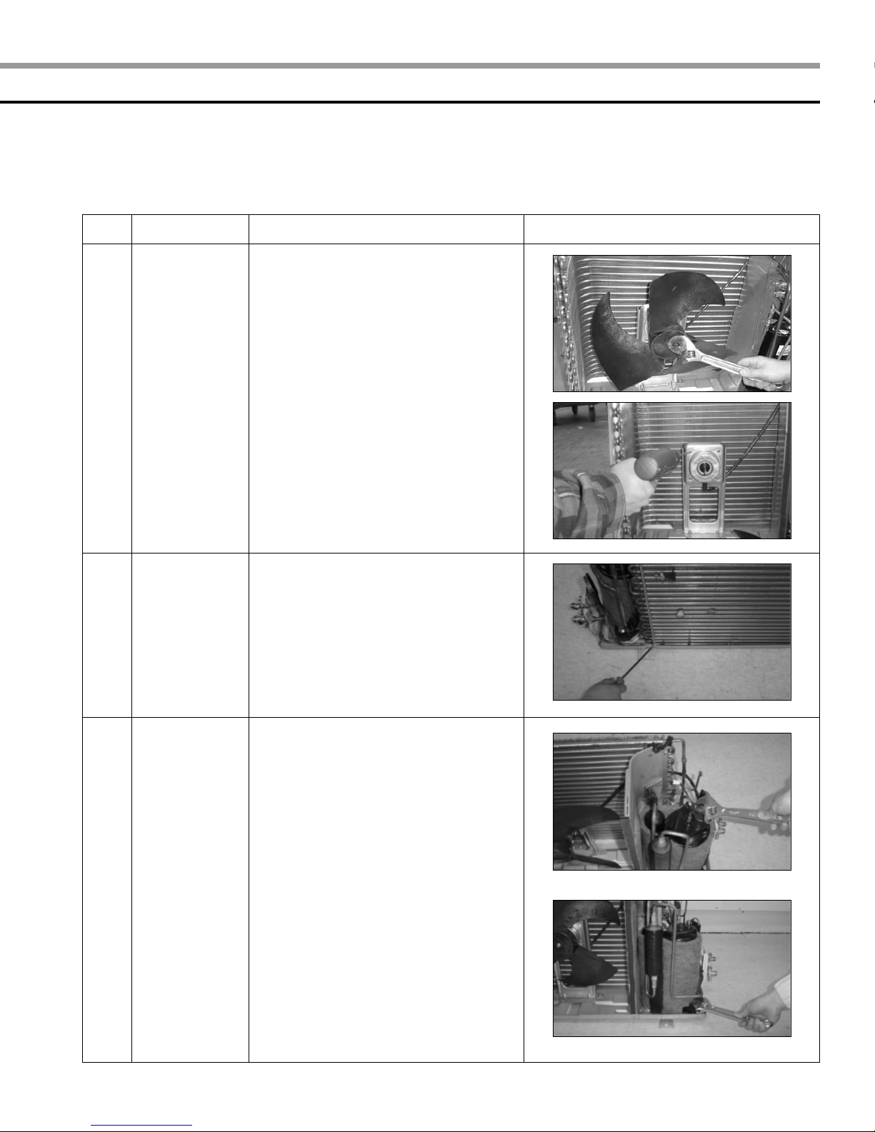
Fan Motor
1) Loosen four screws and separate
Guard Fan from the front cabinet.

No. Part Procedure Remark
2) Remove the nut flange
(Turn to the clockwise).
3)Separate the fan.
4)Loosen four screws to separate the motor.
3
4
Heat
Exchanger
Compressor
1)Release the refrigerant.
2)Loosen two screws of left and right side.
3)Disassemble the inlet and outlet pipe by
welding.
4)Separate the heat exchanger.
1)Release the refrigerant.
2)Loosen the nut on the terminal cover
and open the terminal cover.
3)Separate the OLP and the compressor
wire.
4)Disassemble the inlet and outlet pipe
of compressor by welding.
5)Disassemble the inlet and outlet pipe
of condenser by welding.
6) Loosen three bolts of the lower part.
7)Separate the compressor.
7

ΙΙ
Disassemble and reassemble(cont’d)
■ US12AA(B)MCF
No. Part Procedure Remark
1
Common Work
1) Loosen a screw and separate the cover
E-part.
2)Separate the connection wire from the
terminal block.
3) Loosen thirteen screws and separate
the front cabinet.
4) Loosen a screw of the control box.
5) Loosen four screws and separate the
side cabinet.
8
No. Part Procedure Remark
2
3
Fan and Motor
Heat Exchanger
1) Remove the nut flange
(Turn to the clockwise).
2) Separate the fan.
3) Loosen four screws to separate the motor.
4) Loosen five screws and separate the
motor bracket from the base.
1)Release the refrigerant.
2)Loosen screws of left and right side.
3)Disassemble the inlet and outlet pipe by
welding.
4)Separate the heat exchanger.
4
Compressor
1)Release the refrigerant.
2)Open the terminal cover of compressor
and unscrew the connection terminal.
3)Separate the OLP and the compressor
wire.
4)Disassemble the inlet and outlet pipe of
compressor by welding.
5) Loosen three bolts of the lower part.
6) Separate the compressor.
9
ΙΙΙΙ
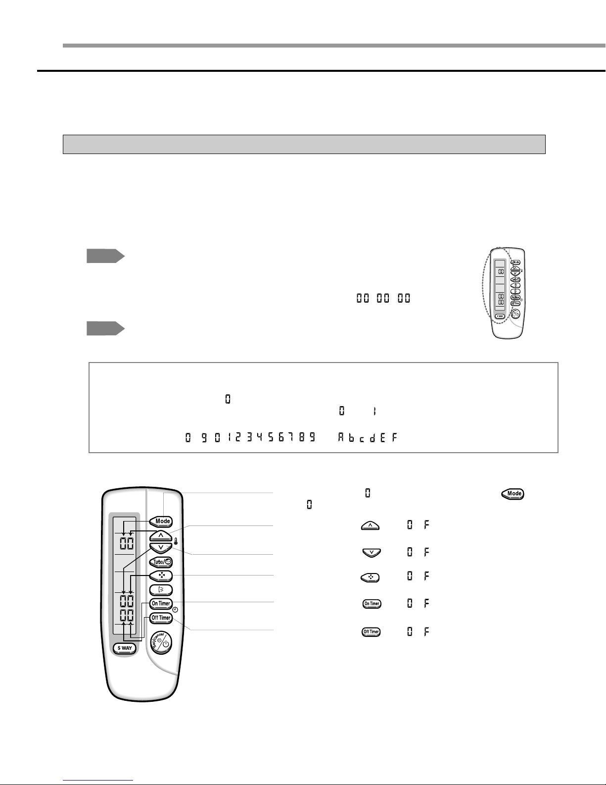
Set up the option code
The method for setting up the model option with the remote control
◆ It is necessary to set up option codes after replacing the main PCB with service parts.
Make sure that you can set up option codes of the remote control after replacing the main PBA.
Otherwise, the unit won’t be working properly and all LED lamps on display will be flickering.
Step 1
Step 2
NNNNoooottttee
Preparing for the remote control to the main PCB option set.
1. Remove the battery from the remote control.
2. Press the temperature button simultaneously and insert the battery again.
3. Make sure the remote control display shown as .
Preparing for the remote control option set.
ee
In case that the wrong letter has been selected; continue to press the button until the
correct letter appears.
1. If the number “ ”appears on the display, proceed to the second stage.
2. Every time you press the 1) and 7) button, “ ” and “ ” continue to appear.
3. Every time you press the 2), 3), 4), 5), 6), 8), 9), 10), 11), 12) button, the number increases
from ~ ( , , , , , , , , , ) and , , , , , in order.
1) If the first number is , it is correct. Otherwise, press the button
until appears.
2) When pressing the button ~ on the display, select one of them.
10
3) When pressing the button ~ on the display, select one of them.
4) When pressing the button ~ on the display, select one of them.
5) When pressing the button ~ on the display, select one of them.
6) When pressing the button ~ on the display, select one of them.

7) If the first number is , it is correct. Otherwise, press the button
until appears.
8) When pressing the button ~ on the display, select one of them.
9) When pressing the button ~ on the display, select one of them.
10) When pressing the button ~ on the display, select one of them.
11) When pressing the button ~ on the display, select one of them.
12) When pressing the button ~ on the display, select one of them.
Step 3
Step 4
Step 5
NNNNoooottttee
Reconfirming the option set after completing
Example : 000000-1700b7
Press the button for the “ ” mode and the display will be shown as .
Press the button for the “ ” mode and the display will be shown as .
Pressing the (On/Off)button
When pressing the (On/Off)button in the direction of the remote control for unit,
it sounds beep or ringing and the first LED lamp on the left side is flickering at the
same time, then the input option is completed. If it doesn’t sound ringing, try again by
pressing the (On/Off)button.
Testing the unit
1 Remove the battery from the remote control.
2. Insert the battery into the remote control.
3. Press the (On/Off)button in the direction of the remote control for set.
Error mode
ee
1. If all lamps of the indoor units are flickering, plug out and in again and press the
(On/Off) button again.
2. If the unit doesn’t work properly or all lamps are continuously flickering after setting the option
code, check that the option code is set properly for its own model.
11

ΙΙΙΙ
Set up the option code(cont’d)
A table of the option code
Model
AS07A5MA
AS07A6MA
AS09A5MAF
AS09A6MAF
AS12AAMCF
AS12ABMCF
Option code
010000-1700b7
000000-1700b7
010000-1700Fb
000000-1700Fb
010000-170340
000000-170340
12

ΙΙΙΙΙΙ
Troubleshooting
1 Items to be checked first
1) The input voltage should be voltage rating within ±10% range.
The air conditioner may not operate properly if the voltage is out of this range.
2) Is the connection cable linking the indoor unit and the outdoor unit properly?
The indoor unit and the outdoor unit shall be linked by five cables.
Check the terminals if the indoor unit and outdoor unit are properly linked by the same number of cables.
Otherwise the air conditioner may not operate properly.
3) When a problem occurs due to the contents illustrated in the table below, it is not a symptom related
to the malfunction of the air conditioner.
No.
The STD operation indicator, LED blinks when a
1
power plug of the indoor unit is plugged in at first.
In the Cool mode, the compressor does not operate
at a room temperature higher than the setting
temperature while the indoor fan operates.
2
The Fan speed operating is not allowed in the Auto
3
or Dry mode.
Compressor stops operating intermittently in the Dry
4
mode.
Timer LED of the indoor unit lights up
and the air conditioner does not operate.
5
The compressor stops intermittently in the Cool or
Dry mode, and the fan speed of the indoor unit
6
decreases.
Operation of air conditioner
It indicates power is on. The LED stops blinking if the
On/Off button on the remote control is pushed.
It happens after three minutes when the compressor is
reoperated. The same phenomenon occurs when a power
is on. As a phenomenon that the compressor is
reoperated after three minutes, the indoor fan is adjusted
automatically with reference to a temperature of the air.
The speed of the indoor fan is set to LL in the Dry mode.
The Fan speed is five steps are selected automatically in
the Auto mode.
The compressor is controlled automatically in the Dry
mode depending on the room temperature and humidity.
The timer is being activated and the unit is in the ready
mode. The unit operates normally if the timer operation is
cancelled.
The compressor stops intermittently or the fan speed of the
indoor unit decreases to prevent inside/outside air from
freezing depending on the inside/outside air temperature.
Explanation
4) Indoor unit observes operation condition of the air conditioner and displays self diagnosis on the
display panel.
No.
STD LED blinking (1Hz)
1
TIMER LED blinking (1Hz)
2
STD and TIMER LED blinking (1Hz)
3
NATURE LED blinking (1Hz)
4
All LED blinking (1Hz)
5
Display
Self Diagnosis
Restore from power failure (input initial power)
Indoor unit Room sensor Error (open or short)
Indoor unit heat exchanger temperature sensor Error (open or short)
Indoor fan malfunctioning (for speed is below 450rpm)
Option Error
13
ΙΙΙΙΙΙ
Troubleshooting (cont’d)
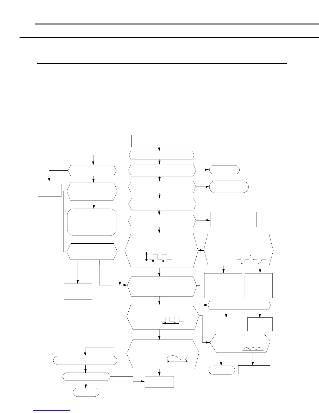
2 Abnormal diagnosis by symptom
1. No Power - Initial diagnosis
1. No Power - Initial diagnosis
1) Checklist :
(1) Is input voltage normal?
(2) Is AC power linked correctly?
(3) Is output voltage of DC regulator IC KA78L05 (IC02) normal? (4.5VDC-5.5VDC)
2) Troubleshooting procedure
Remove the power cord and plug in
again in approx. five seconds
14
YES
Replace PCB
display
Is DC voltage of PCB
display normal?
NO
Is voltage rating within ±10%
range applied to the primary
side(~,~) of the “BD71”?
NO
Check linkage between
a power cord and
a terminal tap
Check fuse
Does 325VDC appear in
the secondary side (+, -)
of “BD71”?
YESNO
Replace
SMPS PARTS
Replace resonator (X301)
Is operation normal?
YES
OK
NO
Does the lamp blink?
Does it start operating when
you push the On/Off button
on the remote control?
Is transmission display of the
remote control unit blinking?
Does the ‘beep’ sound from the
NO
Is DC voltage of the PCB module
Are voltages of #33 (IC04 : compressor)
of Micom normal? 5VDC
Is voltage of #32 (IC04 : indoor fan) of
DC5V
Is voltage of #10(IC04) terminal of Micom normal?
Is voltage of #9(IC04) terminal of Micom normal?
Is voltage of #3(IC04) terminal of
Are voltages of #12(IC04) and
NO
NO
#11(IC04) of Micom normal?
YES
NO
YES
main unit?
YES
normal?
YES
Micom normal?
10ms
NO
0VDC
5VDC
YES
Micom normal?
10ms
YES
250ns
YES
Replace
Micom
YES
NO
NO
YES
NO
NO
Normal
Refer to remote control
unit abnormal diagnosis
Replace PCB
module
.
Are voltages of RY71(Compressor)
normal? DC12V
Is voltage of SS71(indoor fan)?
YES
Check connections
of compressor
and indoor fan.
Is output voltage of ICO2 normal?
YES
Check PCB pattern
Replace the main PCB
Is voltage output terminal of
PC814A(PC02) normal?
YES
OK
Replace
RY71 and
SS71
Replace ICO2
NO
Replace PC814A(PC02)
NO
NO
 Loading...