

Samsung AR24RXWXCWKNEU, AR09RXWXCWKNEU, AR09RXPXBWKXEU, AR12RXPXBWKXEU, AR18RXPXBWKXEU Service Manual
...
AIR CONDITIONER CONTENTS
SPLIT-TYPE AIR CONDITIONER
OUTDOOR UNIT
MODEL CODE
INDOOR UNIT
1. Precautions
2. Pr
cations
3. Alignment and Adjustments
4. Disassembly and Reassembly
5. ASSY CONTROL
6. Electrical Parts List
7. Wiring Diagram
8. PCB Diagram
9. Operating Instructions
10. Troubleshooting
11.Block Diagram
12. Reference Sheet
AR09RXPXBWKNEU
AR12RXPXBWKNEU
AR18RXPXBWKNEU
AR24RXPXBWKNEU
AR09RXWXCWKNEU
AR12RXWXCWKNEU
AR18RXWXCWKNEU
AR24RXWXCWKNEU
AR09RXPXBWKXEU
AR12RXPXBWKXEU
AR18RXPXBWKXEU
AR24RXPXBWKXEU
AR09RXWXCWKXEU
AR12RXWXCWKXEU
AR18RXWXCWKXEU
AR24RXWXCWKXEU
AR09RXPXBWKNEU
AR12RXPXBWKNEU
AR18RXPXBWKNEU
AR24RXPXBWKNEU
AR09RXWXCWKNEU
AR12RXWXCWKNEU
AR18RXWXCWKNEU
AR24RXWXCWKNEU
AR09RXWXCWKXEU
AR12RXWXCWKXEU
AR09RXPXBWKXEU
AR12RXPXBWKXEU
AR18RXPXBWKXEU
AR24RXPXBWKXEU
AR18RXWXCWKXEU
AR24RXWXCWKXEU

2
Contents
1. Precautions 4
1-1 Installing the air conditioner 4
1-2 Power supply and circuit breaker 4
1-3 During operation 4
1-4 Disposing of the unit 5
1-4 Others 5
2. Product Specications 6
2-1 The Feature of Product 6
2-2 Product Specifications 7
2-3 The comparative specifications of product 8
2-4 Accessory and option specifications 10
3. Alignment and Adjustments 11
3-1 Test mode 11
3-2 Display Error and Check Method 12
3-3 Setting Option Setup Method 14
4. Disassembly and Reassembly 19
4-1 Indoor Unit 20
4-2 Outdoor Unit 29
5. ASSY CONTROL 45
5-1 ASSY KIT CODE DB92-04408A 45
5-2 ASSY KIT CODE DB92-04409A 46
5-3 ASSY KIT CODE DB92-04375B 47
5-4 ASSY KIT CODE DB92-04376B 48
5-5 ASSY KIT CODE DB92-04378B 49
5-6 ASSY KIT CODE DB92-04379B 50
6. Electrical Parts List 51
6-1 INDOOR MAIN PCB CODE DB92-04101B 51
6-2 OUTDOOR MAIN PCB CODE DB92-04029D 57
6-3 OUTDOOR PCB INVERTER CODE DB92-04025C 61
6-4 OUTDOOR PCB INVERTER CODE DB92-04027B 69
6-5 ASSY PCB DISPLAY CODE DB92-04106A 77
7. Wiring Diagram 78
7-1 Indoor unit 78
7-2 Outdoor unit 80
8. PCB Diagram 83
8-1 Indoor main PCB code 83
8-2 Outdoor main PCB code 84

3
Contents
9. Operating Instructions 90
9-1 Name of Each Part 90
9-2 Wireless Remote Control-Buttons and Display 91
10. Troubleshootin 92
10-1 Items to be checked First 92
10-2 Communication Error 93
10-2-1 Communication Error 93
10-2-2 Indoor temperature sensor Error 94
10-2-3 Indoor fan motor speed detecting error (BLDC fan) 95
10-2-4 Outdoor temperature sensor error 96
10-2-5 Outdoor Cond temperature sensor error 97
10-2-6 Outdoor Discharge temperature sensor error 98
10-2-7 Operation condition secession error 99
10-2-8 EEPROM error/OTP error 100
10-2-9 Outdoor Fan motor error 101
10-2-10 Compressor starting error 102
10-2-11 Compressor wire missing error/rotation error 103
10-2-12 Current sensor error/Input current sensor error 104
10-2-13 O.C(Over Current) error 105
10-2-14 No power outdoor (Initial Diagnosis) (Not displayed) 107
10-2-15 When the Up/Down, Left/Right, Grill louver motor does not operate 108
10-2-16 When the remote control is not receiving 109
10-2-17 Smart Install error 110
10-2-18 Outdoor OLP over temperature error (One way Inverter Only) 111
11. Block Diagram 112
11-1 Indoor unit 112
11-2 Outdoor unit 113
12. Reference Sheet 116
12-1 Low Refrigerant Pressure Distribution 116
12-2 Pressure & Capacity mark 116
12-3 Q & A for Non-trouble 117
12-4 Cleaning /Filter Change 120
12-5 Installation 123
12-6 Installation Diagram of Indoor Unit and Outdoor Unit 124
12-7 Reference sheet 126

4
1-1 Installing the air conditioner
• Uses should not install the air conditioner by themselves. Ask the dealer or authorized company to install
the air conditioner except window-type air conditioner in U.S.A and Canada.
• If you don't install the air conditioner properly, it may cause a fire, a water leakage or an electric shock.
• You must install the air conditioner according to the national wiring regulations and safety regulations.
• Install the indoor unit higher than 2.5m from the floor to avoid the injury caused by the operation of the fan.
(except the window-type air conditioner)
• The manufacturer is not responsible for any accidents or injury caused by an incorrect installation.
• When installing the built-in type air conditioner, keep all electric cables such as the power cable and the
connection cord in pipes, ducts, or cable channels to protect them from the danger of impact or any other
incidents.
1-2 Power supply and circuit breaker
• If the power cord of the air conditioner is damaged, it must be replaced by the manufacturer or a qualified
person in order to avoid a hazard.
• The air conditioner must be plugged into an independent circuit if applicable or connect the power cable to
the auxiliary circuit breaker. An all pole disconnection form the power supply must be incorporated in the
fixed wiring with a contact opening of>3mm.
• Do not extend an electric cord to the air conditioner.
• The air conditioner must be plugged in after you complete the installation.
1-3 During operation
• Do not repair the air conditioner at your discretion. It is recommended to contact a service center directly.
• Never spill any kind of liquid on the air conditioner. If this happens, turn off the air conditioner and contact
an authorized service center.
• Do not insert anything between the airflow blades to prevent damage of the inner fan and consequent
injury. Keep children away from the air conditioner.
• Do not place any obstacles in front of the air conditioner.
• Do not spray any kind of liquid into the indoor unit. If this happens, turn off the air conditioner and contact
a service center.
• Make sure that the air conditioner is well ventilated at all times. Do not place a cloth or other materials over
it.
• Remove the batteries if you don't use the remote control for a long time. (If applicable)
• Use the remote control within 7 meters from the indoor unit. (If applicable)
1. Precautions
5
1-4 Disposing of the unit
• Before the throwing out the air conditioner, remove the batteries from the remote control.
• When you dispose of the air conditioner, consult your dealer. If pipes are removed incorrectly, refrigerant
may blow out and cause air pollution. When it contacts with your skin, it can cause skin injury.
• The package of the air conditioner should be recycled or disposed of properly for environmental reasons.
1-5 Others
• Never store or load the air conditioner upside down or sideways to prevent the damage to the compressor.
• Young children or infirm persons should be always supervised when they use the air conditioner.
• Max current is measured according to IEC standard for safety.
• Current is measured according to ISO standard for energy efficiency.

6
2-1 The Feature of Product
u
2-step cooling
2-step cooling function will quickly cool the room to reach the desired temperature and then
it will adjust the fan speed and ai ow direction automatically to help you stay comfortable and
refreshed.
u
Fast cooling
If you want the strong and cool air, just select Fast function! It will get you the strongest air!
u
Comfort cooling
If you want the comfortable and refreshing air, Comfort function will spread the cool air indirectly
to you, so that you can stay comfortable.
u
Single User
Use the Single User function when you’re along at home. Aside from energy savings from the
inverter technology, the Single User Mode will further minimize your energy consumption and
reduce your electricity bill by adjusting the maximum operating capacity of the compressor.
u
Easy Filter
Thereisnogrilletoremovebeforeseparatingthelterfromtheairconditioner!Therefore,lter
canbecleanedeasilyandmorefrequently.Constantltercleaningwillpreventdustfromenteringtheproductoraccumulatingonthelter.
u
good’sleep function
good’sleep function will allow you to have deep, good night’sleep by adjusting the temperature,
fanspeedandairowdirection.
u
Smart Install
When the installation is done, your product will examine itself through trial operation to check if
it was installed properly.
u
Easy Installation
It’s so easy to install! You can easily hang the product on the wall and connect the pipes
and wires by opening the cover on the bottom of the product. Now you won’t have to tilt
the product to connect the pipe and the wires!
2. Product Specications
7
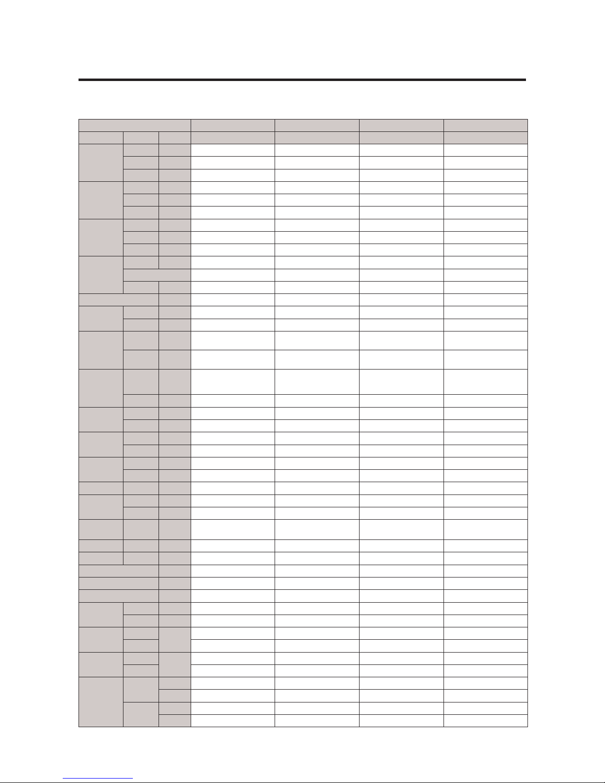
2-2 Product specication
Model AR09RXPXBWK/EU AR12RXPXBWK/EU AR18RXPXBWK/EU AR24RXPXBWK/EU
Rating Mode Unit Wall-mounted Wall-mounted Wall-mounted Wall-mounted
Capacity
T1 Cool W 2500 3500 5000 6500
T3 Cool W - - - -
Heat W 3200 3500 6000 7400
Power Input
T1 Cool W 600 980 1390 1950
T3 Cool W - - - -
Heat W 850 940 1710 2350
Current
T1 Cool A 3.1 4.6 6.4 8.8
T3 Cool A - - - -
Heat - 4 4.4 7. 8 10.5
Efciency
EER W/ W 4.17 3.57 3.60 3.33
- - - - -
COP W/ W 3.76 3.72 3.51 3.15
Dehumidifying l/hr. 0.8 0.8 0.8 0.8
Platform
IDU - F-RAC-06 F-RAC-06 F-RAC-11 F-RAC-11
ODU - N-WW N-WW Q-480 Q-480
Evap
Main -
Φ7,2R*8S*635mm,H1.3,
N.G.S, 1by2
Φ7,2R*8S*635mm,H1.3,
N.G.S, 1by3
Φ7,2R*10S*840mm,H1.3,
N.G.S, 5by5
Φ7,2R*10S*840mm,H1.3,
N.G.S, 5by5
Sub -
Φ7,2R*6S*635mm,H1.3,
N.G.S : (F03-2-1-1)
Φ7,2R*6S*635mm,H1.3,
N.G.S : (F03-2-1-1)
Φ7,2R*5(6)S*840mm,H1.3,
N.G.S : (F05-2-1)
Φ7,2R*5(6)S*840mm,H1.3,
N.G.S : (F05-2-1)
Cond
Main -
Φ7W,2R*24S*716mm,Cor-
rugate1.5, N.G.S, 4by4by2
Φ7W,2R*24S*716mm,Cor-
rugate1.5, N.G.S, 4by4by3
Φ7W,2R*28S*906.8mm,
Corrugate1.5, N.G.S,
4by4by1
Φ7W,2R*28S*906.8mm,
Corrugate1.5, N.G.S,
4by4by1
Sub - - - - -
Comp
Model - UB9AK1090FERTS UB9AK1090FERTS UB9TK3150FE4 UB9TK2150FE4
OLP - - - - -
Motor In
Code - DB31-00636A DB31-00636A DB31-00636A DB31-00637A
Name - - - - -
Motor Out
Code - DB31-00642C DB31-00642C DB31-00642D DB31-00658D
Name - - - - -
Expansion Φ*L - EEVΦ1.4 EEVΦ1.4 EEVΦ1.4 EEVΦ1.4
Refrigerant
type - R-32 R-32 R-32 R-32
charge g 750 g 750 g 1150 g 1150 g
SVC Valve
Liquid /
Gas
- 6.35/9.52 6.35/9.52 6.35/12.7 6.35/15.88
Tube Dis. / Suc. - 9.52/9.52 9.52/9.52 9.52/12.7 9.52/12.7
Drain hose D*L mm 20*550 20*550 20*550 20*550
4-WAY V/V - 1 HP 1 HP 2 HP 2 HP
Power Supply V/Hz/Φ 220-240/50/1 220-240/50/1 220-240/50/1 220-240/50/1
Climate Class - T1 T1 T1 T1
Noise
IDU UT,T dB 41 43 46 51
ODU dB 52 53 57 62
Net Size
(W*D*H)
IDU
mm
828*267*265 828*267*265 1065*301*311 1065*301*311
ODU 720*548*265 720*548*265 880*638*310 880*638*310
Weight
IDU
kg
9.4 9.4 13 .1 13.4
ODU 27. 6 2 7. 6 40. 2 44.8
Operation
range
Cooling
IDU 16˚C~32˚C 16˚C~32˚C 16˚C~32˚C 16˚C~32˚C
ODU -10 °C to 46 °C -10 °C to 46 °C -10 °C to 46 °C -10 °C to 46 °C
Heating
IDU 27 °C or less 27 °C or less 27 °C or less 27 °C or less
ODU -15 °C to 24 °C -15 °C to 24 °C -15 °C to 24 °C -15 °C to 24 °C
8
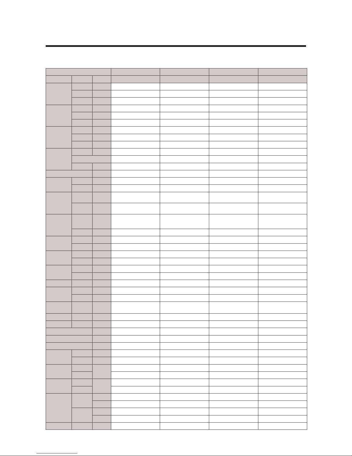
2-2 Product specication
Model AR09RXWXCWK/EU AR12RXWXCWK/EU AR18RXWXCWK/EU AR24RXWXCWK/EU
Rating Mode Unit Wall-mounted Wall-mounted Wall-mounted Wall-mounted
Capacity
T1 Cool W 2750 3500 5000 6500
T3 Cool W - - - -
Heat W 3200 3500 6000 7400
Power Input
T1 Cool W 820 1220 1390 1950
T3 Cool W - - - -
Heat W 840 940 1710 2350
Current
T1 Cool A 4.0 5.6 6.4 8.8
T3 Cool A - - - -
Heat - 4.0 4.3 7. 8 10.5
Efciency
EER W/ W 3.35 2.87 3.6 3.33
- - - - -
COP W/ W 3.81 3.72 3.51 3.15
Dehumidifying l/hr. 0.8 0.8 0.8 0.8
Platform
IDU - F-RAC-06 F-RAC-06 F-RAC-11 F-RAC-11
ODU - N-V2MD N-V2MD Q-480 Q-480
Evap
Main -
Φ7,2R*8S*635mm,H1.3,
N.G.S, 1by2
Φ7,2R*8S*635mm,H1.3,
N.G.S, 1by2
Φ7,2R*10S*840mm,H1.3,
N.G.S, 5by5
Φ7,2R*10S*840mm,H1.3,
N.G.S, 5by5
Sub -
Φ7,2R*6S*635mm,H1.3,
N.G.S : (F03-2-1-1)
Φ7,2R*6S*635mm,H1.3,
N.G.S : (F03-2-1-1)
Φ7,2R*5(6)S*840mm,H1.3,
N.G.S : (F05-2-1)
Φ7,2R*5(6)S*840mm,H1.3,
N.G.S : (F05-2-1)
Cond
Main -
Φ7W,2R*20(21)
S*639/611mm,Corru-
gate1.5, N.G.S, 4by4by2
Φ7W,2R*20(21)
S*639/611mm,Corru-
gate1.5, N.G.S, 4by4by2
Φ7W,2R*28S*906.8mm,
Corrugate1.5, N.G.S,
4by4by1
Φ7W,2R*28S*906.8mm,
Corrugate1.5, N.G.S,
4by4by1
Sub - - - - -
Comp
Model - UB9AK1090FJR UB9AK1090FJR UB9TK3150FE4 UB9TK2150FE4
OLP - - - - -
Motor In
Code - DB31-00636A DB31-00636A DB31-00636A DB31-00637A
Name - - - - -
Motor Out
Code - DB31-00642C DB31-00642C DB31-00642D DB31-00658D
Name - - - - -
Expansion Φ*L - EEVΦ1.4 EEVΦ1.4 EEVΦ1.4 EEVΦ1.4
Refrigerant
type - R-32 R-32 R-32 R-32
charge g 700 g 700 g 1150 g 750 g
SVC Valve
Liquid /
Gas
- 6.35/9.52 6.35/9.52 6.35/12.7 6.35/15.88
Tube Dis. / Suc. - 9.52/9.52 9.52/9.52 7.94/12.7 9.52/12.7
Drain hose D*L mm 20*550 20*550 20*550 20*550
4-WAY V/V - - - - -
Power Supply V/Hz/Φ 1 HP 1 HP 2HP 2 HP
Climate Class - 220-240/50/1 220-240/50/1 220-240/50/1 220-240/50/1
Noise
IDU UT,T dB T1 T1 T1 T1
ODU dB 41 44 46 51
Net Size
(W*D*H)
IDU
mm
53 54 57 60
ODU 828*267*265 828*267*265 1065*301*311 1065*301*311
Weight
IDU
kg
660*475*242 660*475*242 880*638*310 880*638*310
ODU 9.4 9.4 1 3.1 13.4
Operation
range
Cooling
IDU 22.9 22 .9 40.2 44.8
ODU 16˚C~32˚C 16˚C~32˚C 16˚C~32˚C 16˚C~32˚C
Heating
IDU -10 °C to 46 °C -10 °C to 46 °C -10 °C to 46 °C -10 °C to 46 °C
ODU 27 °C or less 27 °C or less 27 °C or less 27 °C or less
-15 °C to 24 °C -15 °C to 24 °C -15 °C to 24 °C -15 °C to 24 °C
9
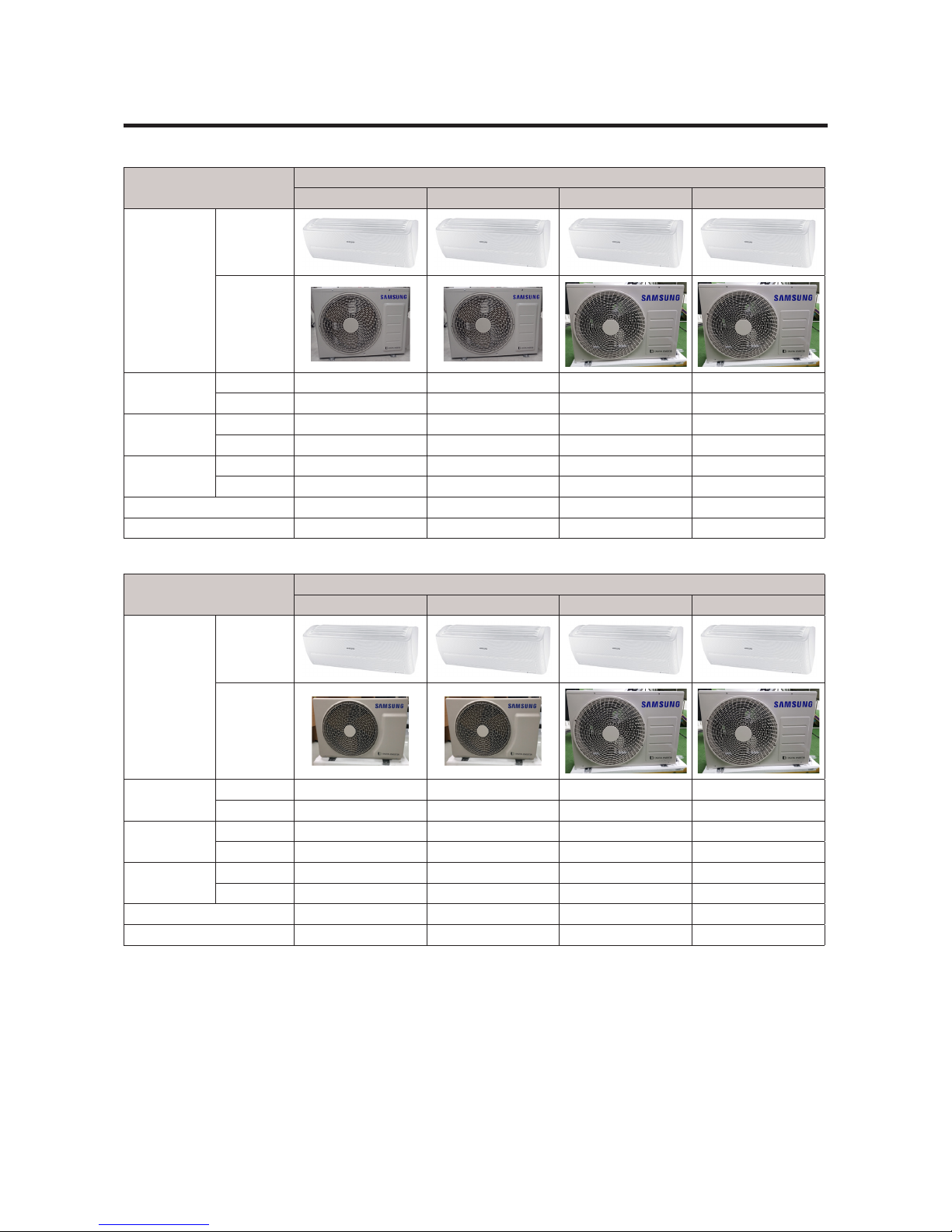
2-3 The comparative specication of product
Model
DEVELOPMENT MODEL
AR09RXPXBWK/EU AR12RXPXBWK/EU AR18RXPXBWK/EU AR24RXPXBWK/EU
Design
Indoor Unit
Outdoor Unit
Net Weight
Indoor Unit 9. 4 9. 4 1 3.1 13.4
Outdoor Unit 2 7. 6 2 7. 6 40.2 44.8
Net Dimension
Indoor Unit 828*267*265 828*267*265 1065*301*311 1065*301*311
Outdoor Unit 720*548*265 720*548*265 880*638*310 880*638*310
Noise
Indoor Unit 41 43 46 51
Outdoor Unit 52 53 57 62
Air Purifying System EASY CLEAN FILTER EASY CLEAN FILTER EASY CLEAN FILTER EASY CLEAN FILTER
Indoor Display 88 SEG 88 SEG 88 SEG 88 SEG
Model
DEVELOPMENT MODEL
AR09RXPXBWK/EU AR12RXPXBWK/EU AR18RXPXBWK/EU AR24RXPXBWK/EU
Design
Indoor Unit
Outdoor Unit
Net Weight
Indoor Unit 9. 4 9. 4 1 3.1 13.4
Outdoor Unit 22.9 22.9 40.2 44.8
Net Dimension
Indoor Unit 828*267*265 828*267*265 1065*301*311 1065*301*311
Outdoor Unit 660*475*242 660*475*242 880*638*310 880*638*310
Noise
Indoor Unit 41 44 46 51
Outdoor Unit 53 54 57 60
Air Purifying System EASY CLEAN FILTER EASY CLEAN FILTER EASY CLEAN FILTER EASY CLEAN FILTER
Indoor Display 88 SEG 88 SEG 88 SEG 88 SEG
10
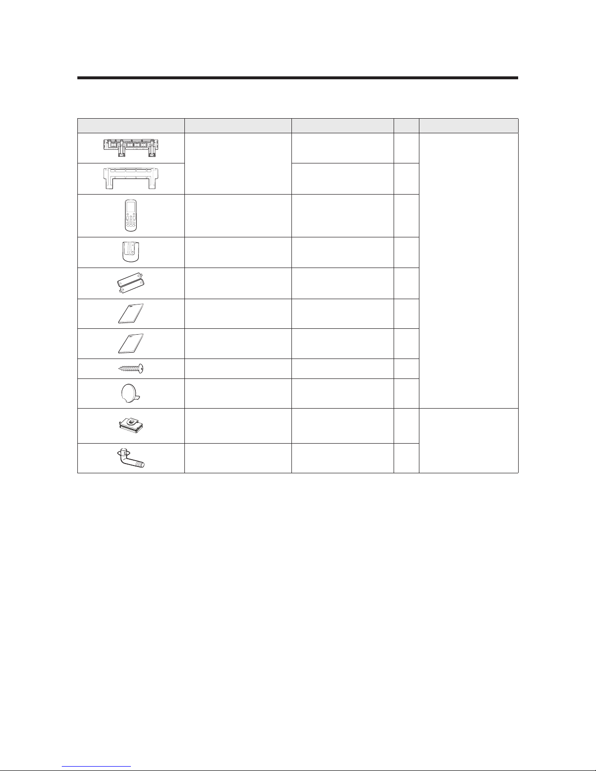
2-4 Accessoray and option specications
Item Descriptions Code No. Q’ty Remark
ASSY HANGER
DB90-07732A
(F-RAC-06)
1
Indoor unit case
DB90-07731A
(F-RAC-11)
1
ASSY WIRELESS REMOCON
DB93-16761C 1
HOLDER REMOCON DB61-06087A 1
BATTERY
4301-000121 2
MANUAL USERS DB68-08138A 1
MANUAL INSTALL DB68-08137A 1
SCREW-TAPPING 6002-000623 2
CAP-SCREW DB67-01404B 2
Rubber Leg DB67-01533A 4
Outdoor unit case
Drain plug
DB67-20011A 1

11
3-1 Test Mode
u
How to Approach Test Mode
You can approach the test mode by pressing the on/off
switch of indoor unit for 5 seconds.
u
Test mode operation option
After installing the air conditioner, check whether each subordinate is normally operated or not by
operating the test mode.
• When an Error occurs, display the Error Mode.
• Operation Mode : Cool mode. operate the cool mode by operating the compressor by force
without the compressor ON/OFF according to the set temperature/indoor temperature. (Do not
follow the antifreeze control)
• Up-down louver : Up-down swing mode
• Indoor Fan : Turbo
Note
• Because the heat mode operate the cool mode by force not related to the set temperature
/ indoor temperature, check whether each subordinate is operated normally or not after
completing installation and must turn off the power of the air conditioner.
3. Alignment and Adjustments
12
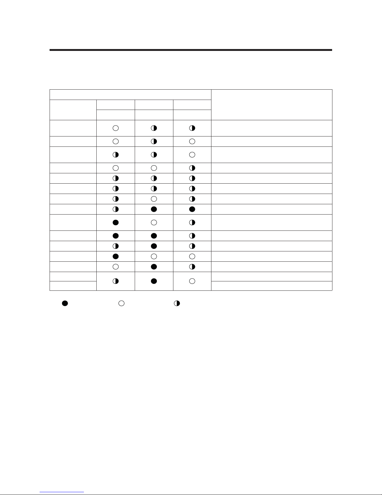
3-2 Display Error and Check Method
3-2-1 Indoor Display Error and Check Mathod
ERROR MODE
DESCRIPTION
7-SEG
LED1 LED2 LED3
Operation Timer Option
E101 , E102
Communication error
(Indoor <-> Outdoor)
E121
ROOM TH sensor error
E122, E123
INDOOR MID, INDOOR IN PIPE-TH
sensor error
E154
Fan error (Indoor)
E162
EEPROM error
E163
Option error
FROM E200
Outdoor error display
E203
Time out comm. (Inv Micom <-> Main Micom)
E422 / E554
EEV or valve close error-Self diagnosis/ Gas
Leak error
E458
Outdoor and Fan error
E461
Comp.starting error
E463
No display about the outdoor condition
E464
IPM over current (O.C) error
E465
Com V_limit/I_limit error
E500 Heatsink overheat or IPM overheat
:LAMP ON
: LAMP OFF
: LAMP BLINK
*Note*
If the set doesn’t work (No power), check the thermal fuse of terminal block OPEN or
SHORT with Multimeter.
*MeasurethethermalfusehousingPIN#1~2:OPEN(disconnection)->defectiveproduct
13
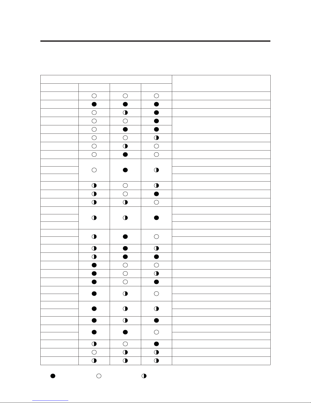
3-2 Display Error and Check Method
3-2-2 Outdoor Display Error and Check Mathod
ERROR MODE
DESCRIPTION
7-SEG YEL GRN RED
-
Power off /VDD NG
-
Power on reset (1sec)
-
Normal operation
-
Abnormal communication
(Indoor <-> Outdoor)
-
E464
IPM over current (O.C) error
E461
Comp. strating error
E470
EEPROM data error (no data)
E466
DC-Link voltage under / Over error
E484 PFC over load error
E483 Over voltage protection error
E221
OUT-TH (Outdoor temperature) sensor error
E416
DIS-TH (Discharge temperature) Over error
E251
DIS-TH (Discharge temperature) sensor error
E468
Current sensor error
E474 Heatsink sensor error
E485 Input current sensor error
E465
Comp. V_limit/ I_limit error
E500 Heatsinkover temperature error
E231
CON-TH (Cond temperature) sensor error
E203
Time out Comp. (Inv Micom <->Main Micom)
E458
Fan error
E471
EEPROM data error (Main Micom <-> INV Micom)
E467
Comp. wire missing error
E440
Prohibit operation condition error (Heating)
E441 Prohibit operation condition error (Cooling)
E469
DC-Link voltage sensor
E488 AC Input voltage sensor
E462
AC Input I_limit trip error
E554
Gas leak error
E422 EEV or valve close error-self diagnosis
E462
Outdoor OLP over temperature error
-
Test operation at Cooling mode
-
Test operation at Heating mode
:LAMP ON
: LAMP OFF
: LAMP BLINK
14
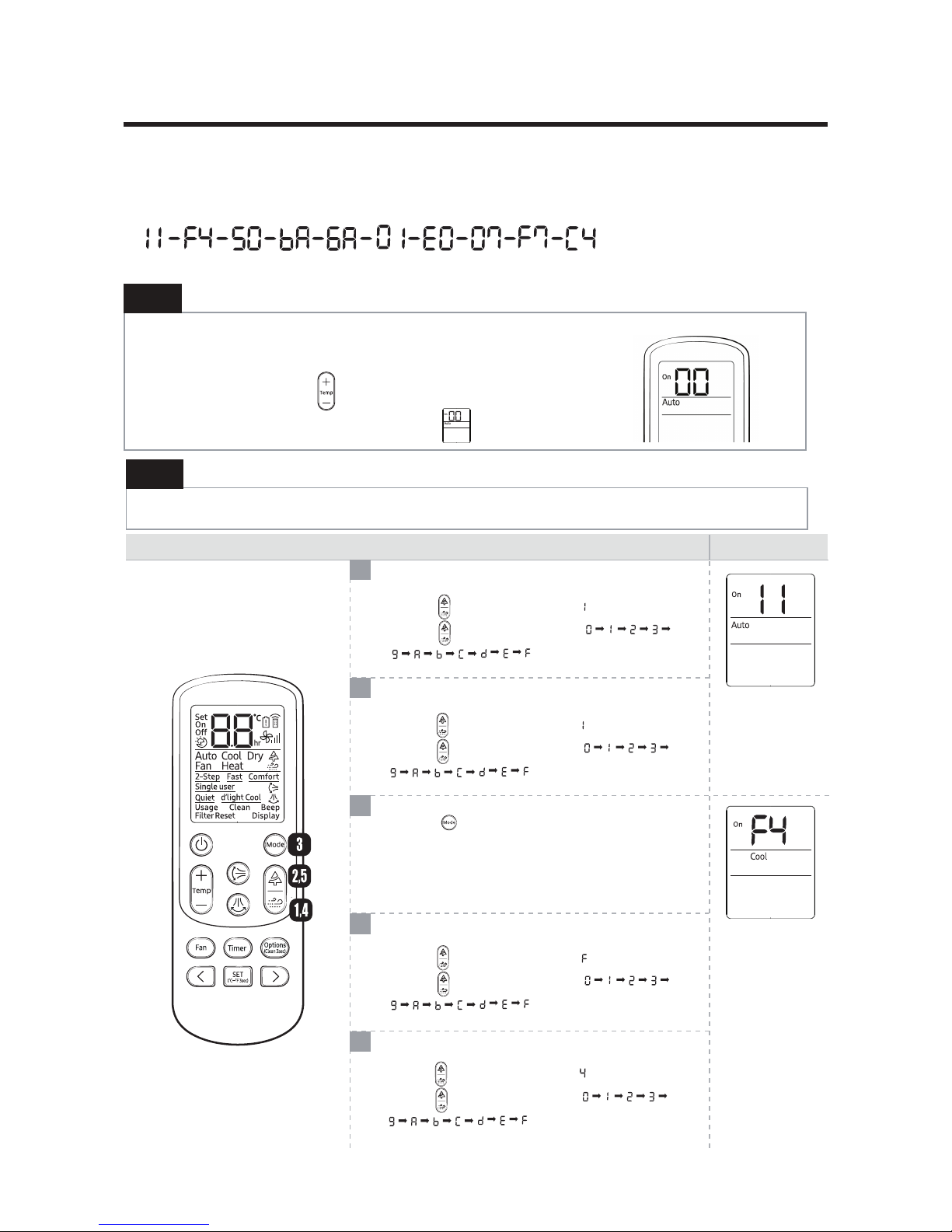
3-3 Setting Option Setup Method
Step 2
Enter the Options Setup mode and select your options asscording to the following procedure.
Ex) Option No. :
Step 1
Enter the Option Setup mode.
1. Tack out the batteries of remote control.
2. Press the temperature button simultaneously and insert the battery again.
3. Make sure the remote control display shown as
Setting option SEG1
Press the button the display panel to .
Press the button repeatedly to select .
⋯
Press the button to set Cool mode.
5
4
3
2
1
Method
Display
Setting option SEG2
Press the button the display panel to .
Press the button repeatedly to select .
⋯
Setting option SEG3
Press the button the display panel to .
Press the button repeatedly to select .
⋯
Setting option SEG4
Press the button the display panel to .
Press the button repeatedly to select .
⋯
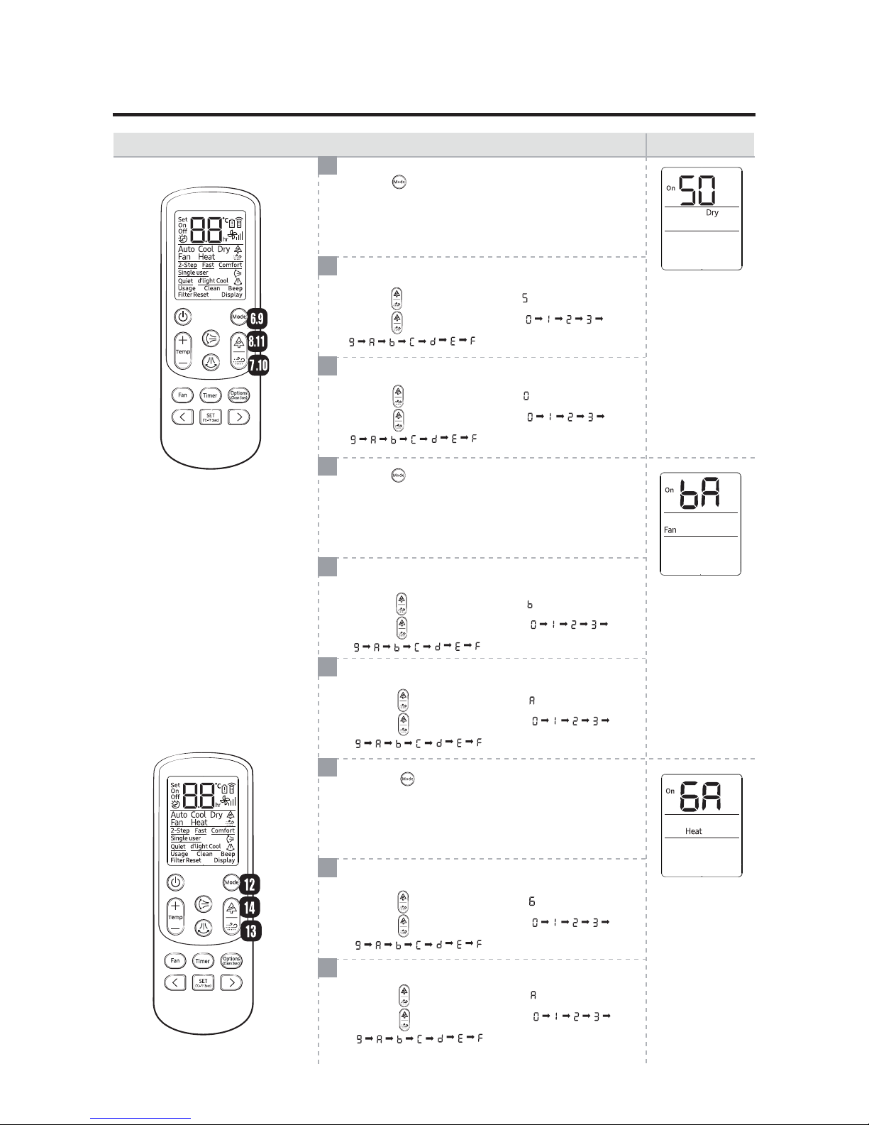
15
6
7
8
9
10
11
12
13
14
Method
Display
Press the button to set Dry mode.
Setting option SEG5
Press the button the display panel to .
Press the button repeatedly to select .
⋯
Setting option SEG6
Press the button the display panel to .
Press the button repeatedly to select .
⋯
Setting option SEG7
Press the button the display panel to .
Press the button repeatedly to select .
⋯
Setting option SEG8
Press the button the display panel to .
Press the button repeatedly to select .
⋯
Setting option SEG9
Press the button the display panel to .
Press the button repeatedly to select .
⋯
Setting option SEG10
Press the button the display panel to .
Press the button repeatedly to select .
⋯
Press the button to set Fan mode.
Press the button to set Heat mode.

16
15
16
17
18
19
20
21
22
23
Method
Display
Setting option SEG16
Press the button the display panel to .
Press the button repeatedly to select .
⋯
Setting option SEG15
Press the button the display panel to .
Press the button repeatedly to select .
⋯
Setting option SEG14
Press the button the display panel to .
Press the button repeatedly to select .
⋯
Setting option SEG13
Press the button the display panel to .
Press the button repeatedly to select .
⋯
Setting option SEG11
Press the button the display panel to .
Press the button repeatedly to select .
⋯
Setting option SEG12
Press the button the display panel to .
Press the button repeatedly to select .
⋯
Press the button to set Auto mode.
Press the button to set Cool mode.
Press the button to set Dry mode.
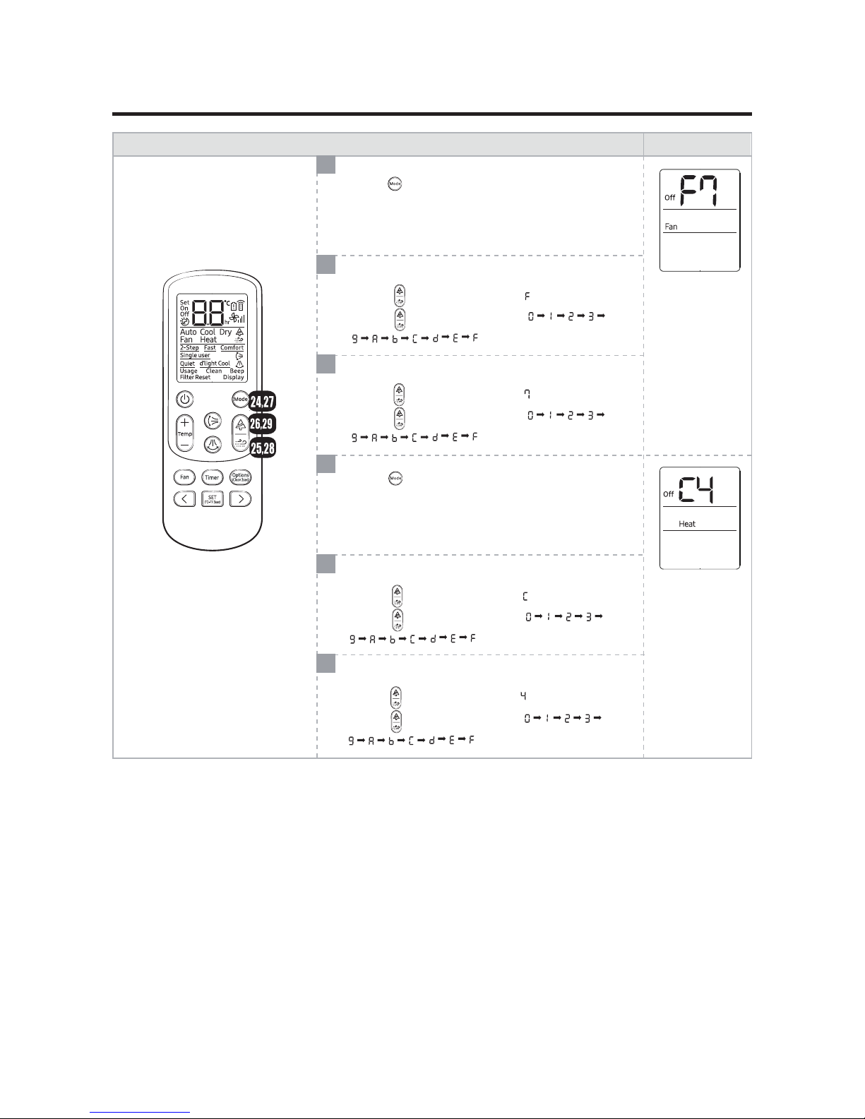
17
24
25
26
27
28
29
설정방 법
표시 부
Press the button to set Fan mode.
Press the button to set Heat mode.
Setting option SEG17
Press the button the display panel to .
Press the button repeatedly to select .
⋯
Setting option SEG18
Press the button the display panel to .
Press the button repeatedly to select .
⋯
Setting option SEG19
Press the button the display panel to .
Press the button repeatedly to select .
⋯
Setting option SEG20
Press the button the display panel to .
Press the button repeatedly to select .
⋯
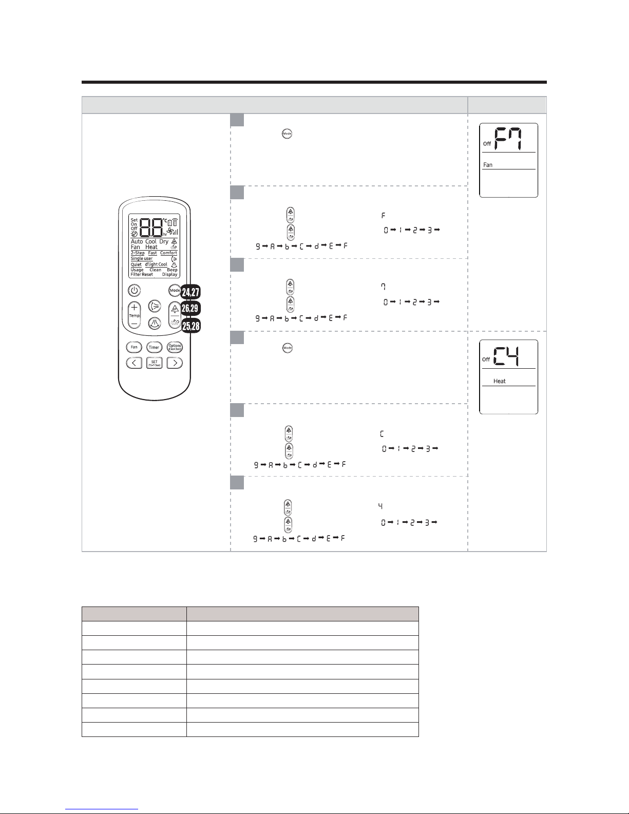
18
24
25
26
27
28
29
설정방 법
표시 부
Press the button to set Fan mode.
Press the button to set Heat mode.
Setting option SEG17
Press the button the display panel to .
Press the button repeatedly to select .
⋯
Setting option SEG18
Press the button the display panel to .
Press the button repeatedly to select .
⋯
Setting option SEG19
Press the button the display panel to .
Press the button repeatedly to select .
⋯
Setting option SEG20
Press the button the display panel to .
Press the button repeatedly to select .
⋯
Option code :
Model Option code
AR09RXPXBWK/EU 011C45-17EA2B-271920-3727C4
AR12RXPXBWK/EU 011C45-17EA4B-272323-3727C4
AR18RXPXBWK/EU 011845-15EA1C-27323C-3727C4
AR24RXPXBWK/EU 011845-16EA4A-27414A-3714C4
AR09RXWXCWK/EU 011C05-17EA29-271920-3715D4
AR12RXWXCWK/EU 011C05-15EA6B-272323-3717D4
AR18RXWXCWK/EU 011805-15EA1C-27323C-3727C4
AR24RXWXCWK/EU 011805-16EA4A-27414A-3714C4
19
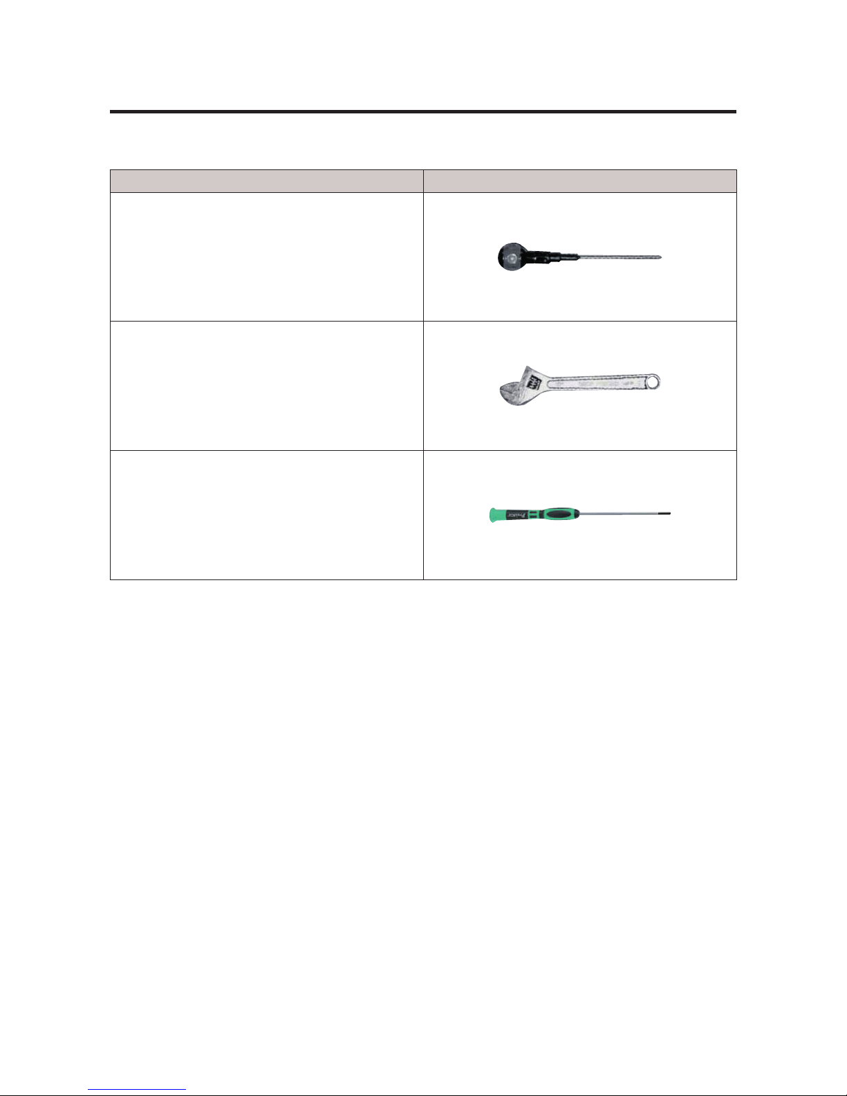
u Necessary Tools
Item Remark
+SCREW DRIVER
Q’ty 1 ea.
To assembly and disassembly the screw
MONKEY SPANNER
Q’ty 1 ea.
To assembly and disassembly the Fan motor and
Compressor
- SCREW DRIVER
Q’ty 1 ea.
To assembly and disassembly the screw
4. Disassembly and Reassembly
20
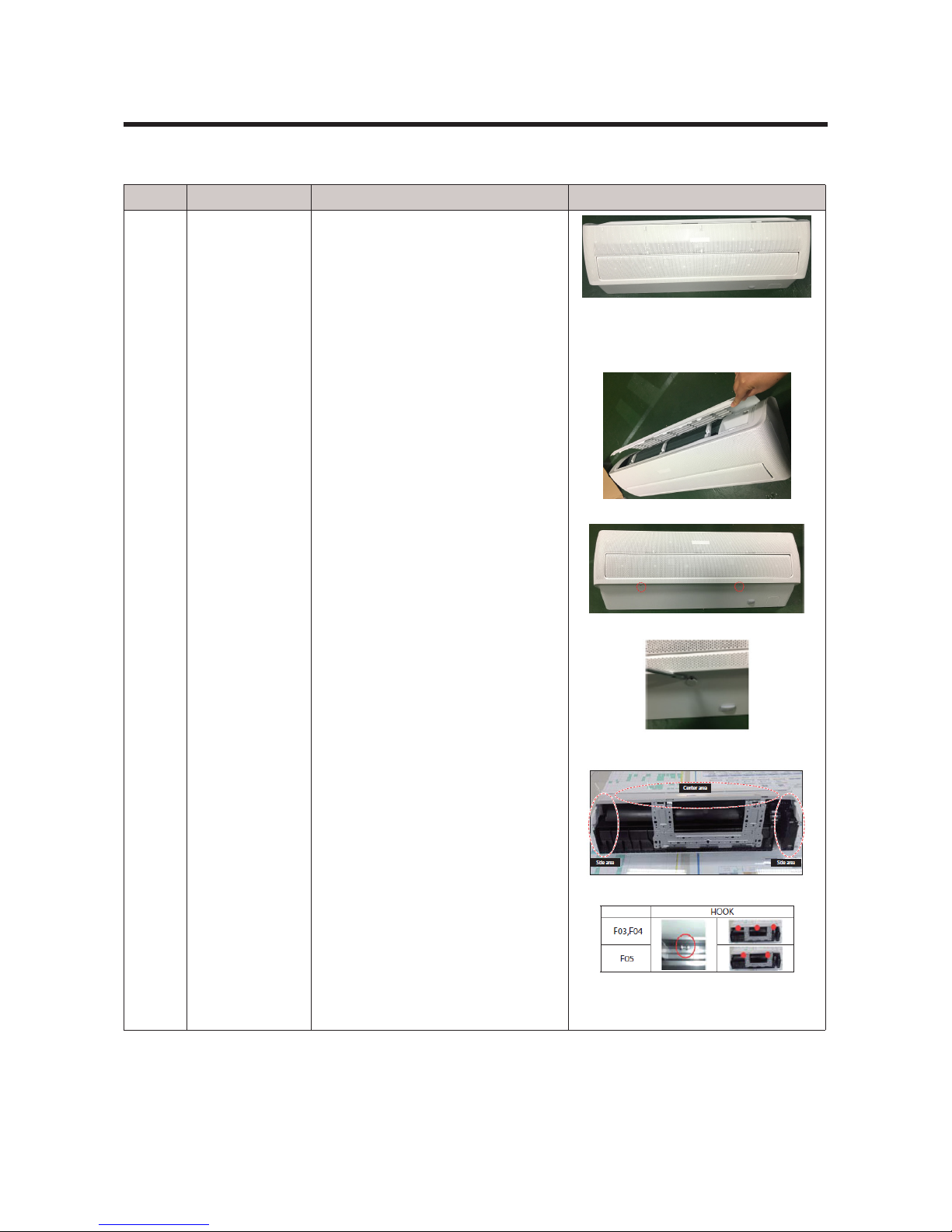
4-1. Indoor Unit
NO. Parts Procedure Remark
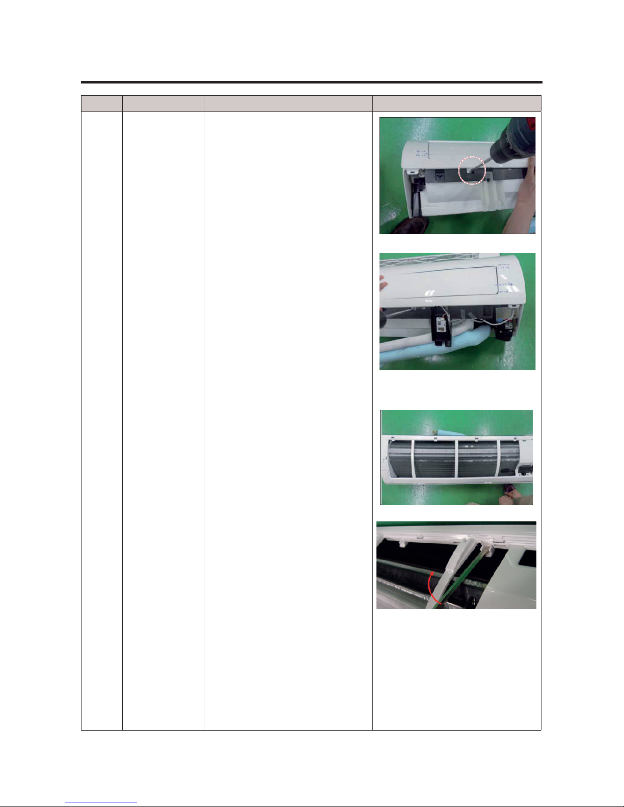
1 PANEL-FRONT 1) Stop the driving of
air conditioner and shut off main
power supply.
2) Detach FILTER PRE from the
PANEL FRONT.
3) Cover Panel is assembled on bottom of indoorunit as shown in the
gure.
Remove the Cap Screw as shown on
the right side and then remove the
screw and separate the Cover Panel.
4)CoverPanelisxedtobodyby
Hook in center area and side area.
21
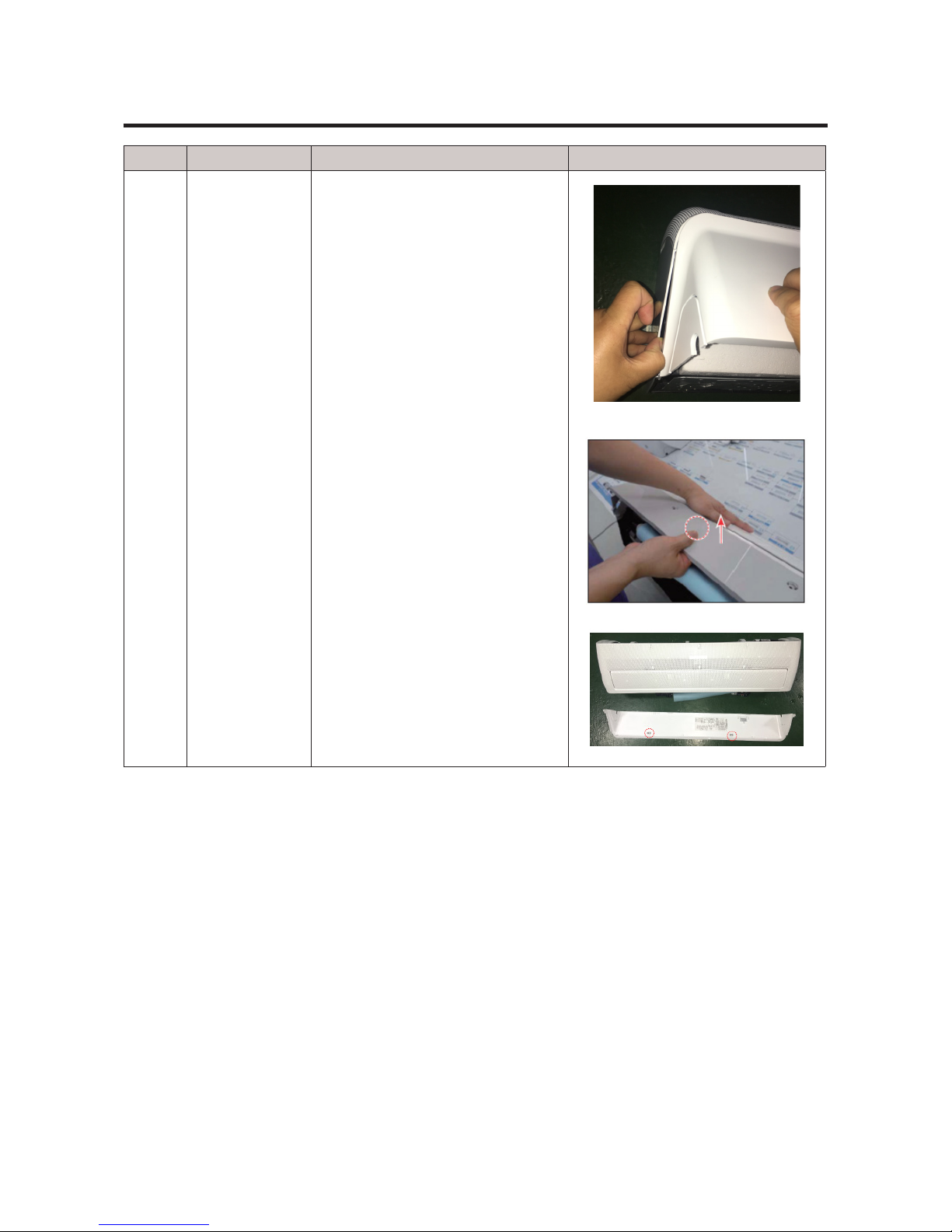
NO. Parts Procedure Remark
1 PANEL-FRONT 5) Separate the hook after
pushing both end of Cover Panel as
showninthegure.(Watchoutfor
the damage of the hook)
6) Raise front part upward obliquely
asshowninthegureandthen
remove the hooks.
22
NO. Parts Procedure Remark
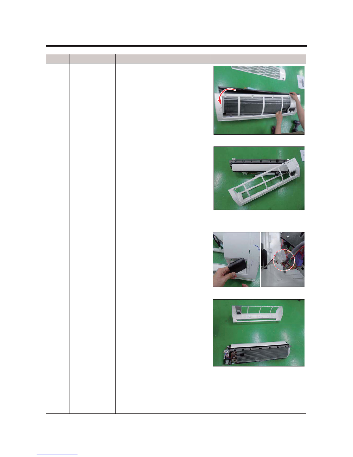
1 PANEL-FRONT
Caution:
Assembly of Cover Panel after
service end.
- Reassembly is in the reverse
order of the removal.
- Piping and drain hose must be
careful not to damage and Progress must be done with both
hands.
23
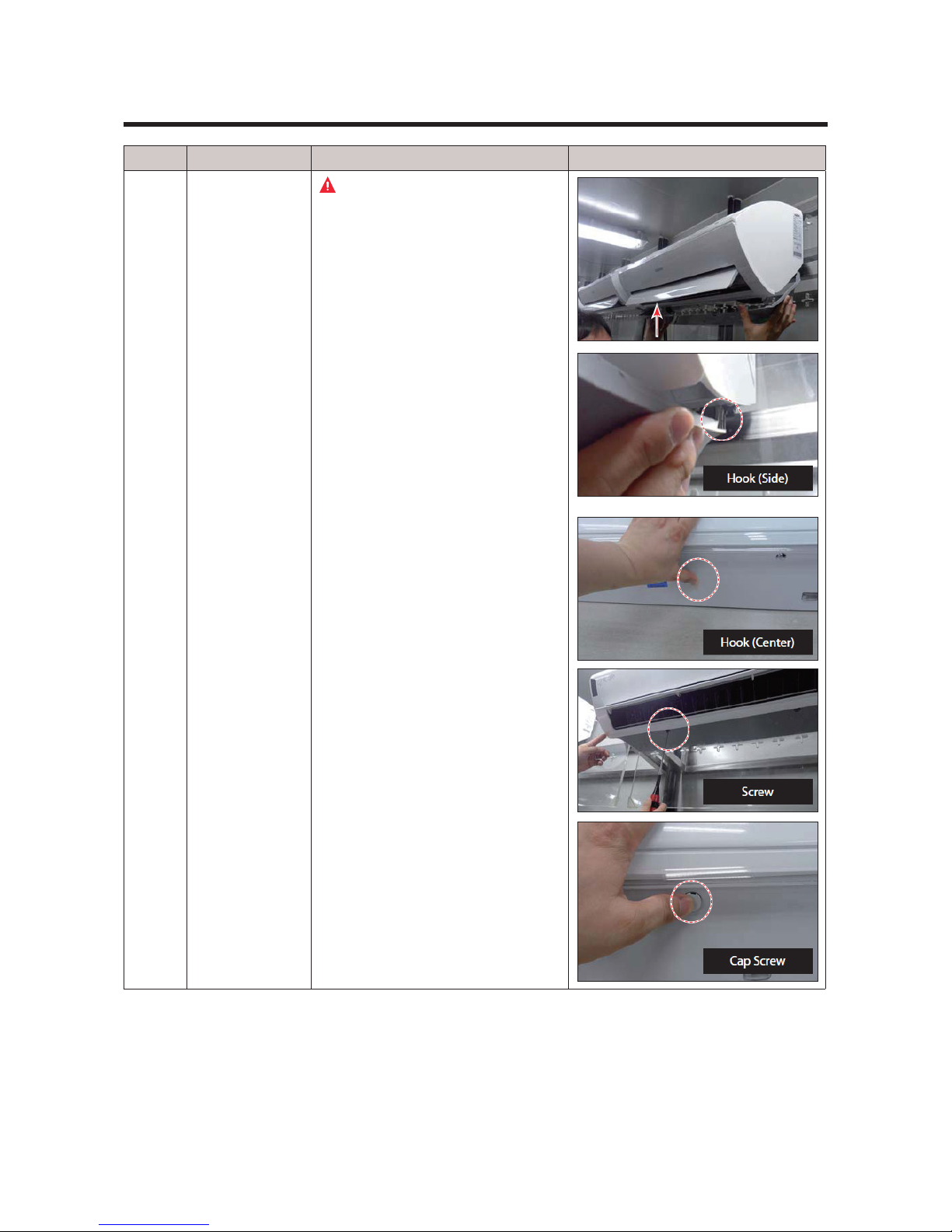
NO. Parts Procedure Remark
1 PANEL-FRONT
7) To detach the PANEL-FRONT
from the main frame, unfasten 2
screws at the bottom. (use + Screw
Driver)
8) To detach the COVER-PANEL
from the main frame, loosen 4
HOOK Structures.
When separate the hook : Use the
(-) screw Driver.
(-)Screw Driver Insert the hook and
then pull the hook as shown on the
right side.
(Watch out for the damage of the
hook)
24
NO. Parts Procedure Remark
1 PANEL-FRONT
9) Remove the Panel Frame from
the Main Frame as shown on the
right side.
10) Remove the WIFI KIT
connector. WIFI KIT connector is
located of Panel Front. (For model
with WIFI KIT)
25
NO. Parts Procedure Remark
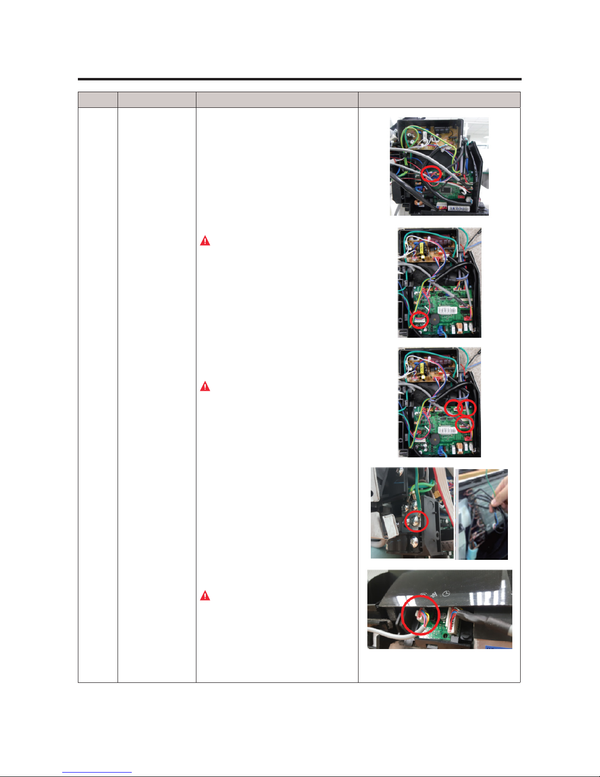
2
CONTORL IN 11) seperate Blade motor
connect wire. Along with a picture
12) Loosen MOTOR Wire.
Caution:
When you separate the
connector, pull pressing the locking button.
13) Loosen the Thermistor wires,
Display wire and Humidity wire
connector.
Caution:
When you separate the
connector, pull pressing the locking button.
14) Loosen the ground wire.
15) Loosen the remote control PCB
wire connector.
Caution:
When you separate the
connector, pull pressing the locking button.

26
NO. Parts Procedure Remark
3
EVAPORATOR 16) Take off the CASE-CONTROL
from the main frame after loosen
the remaining connector.
Caution:
When you separate the
connector, pull pressing the locking button.
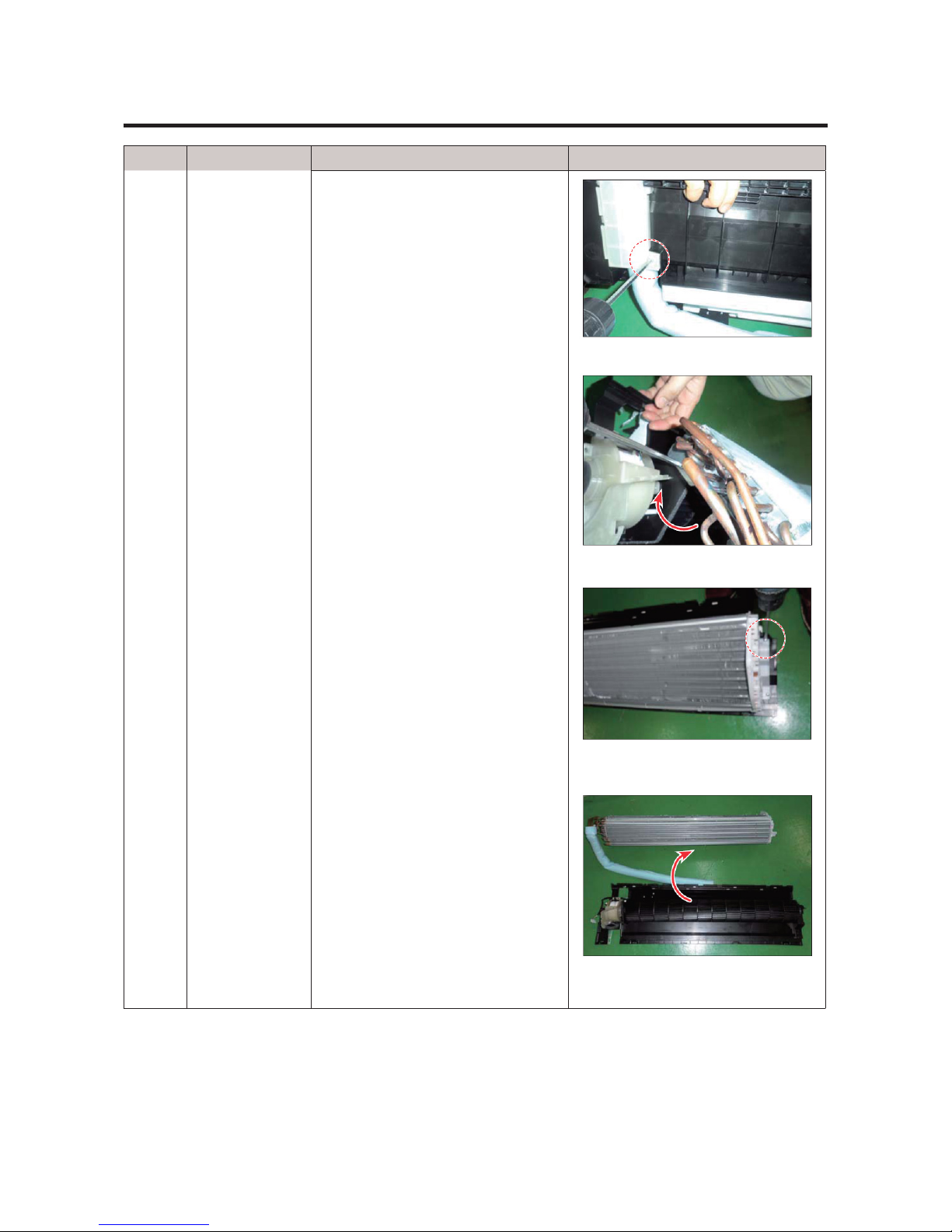
4
TRAY DRAIN 17) To detach TRAY-DRAIN from
the main frame, pull the bottom of
the TRAYDRAIN towards you.
27
NO. Parts Procedure Remark
5
EVAPORATOR 18) Detach the HOLDER PIPE.
19) Unfasten the screw at the left
side.
(use + Screw Driver)
20) Unfasten the screw at the right
side.
(use + Screw Driver)
21) To detach Evaporator from the
main frame, pull the bottom of the
Evaporator towards you.
28
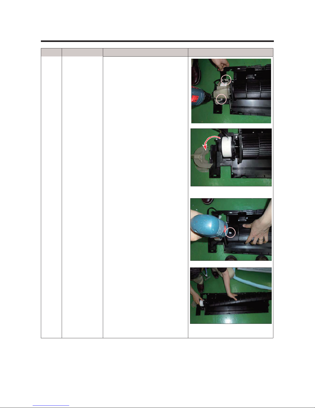
NO. Parts Procedure Remark
6
FAN MOTOR
&
CROSS FAN
22) Unfasten the screw.
(use + Screw Driver)
23) Detach the FAN Motor case.
24) Unfasten the screw a little.
(use + Screw Driver)
25) Pull the CROSS-FAN to the left
side.
29
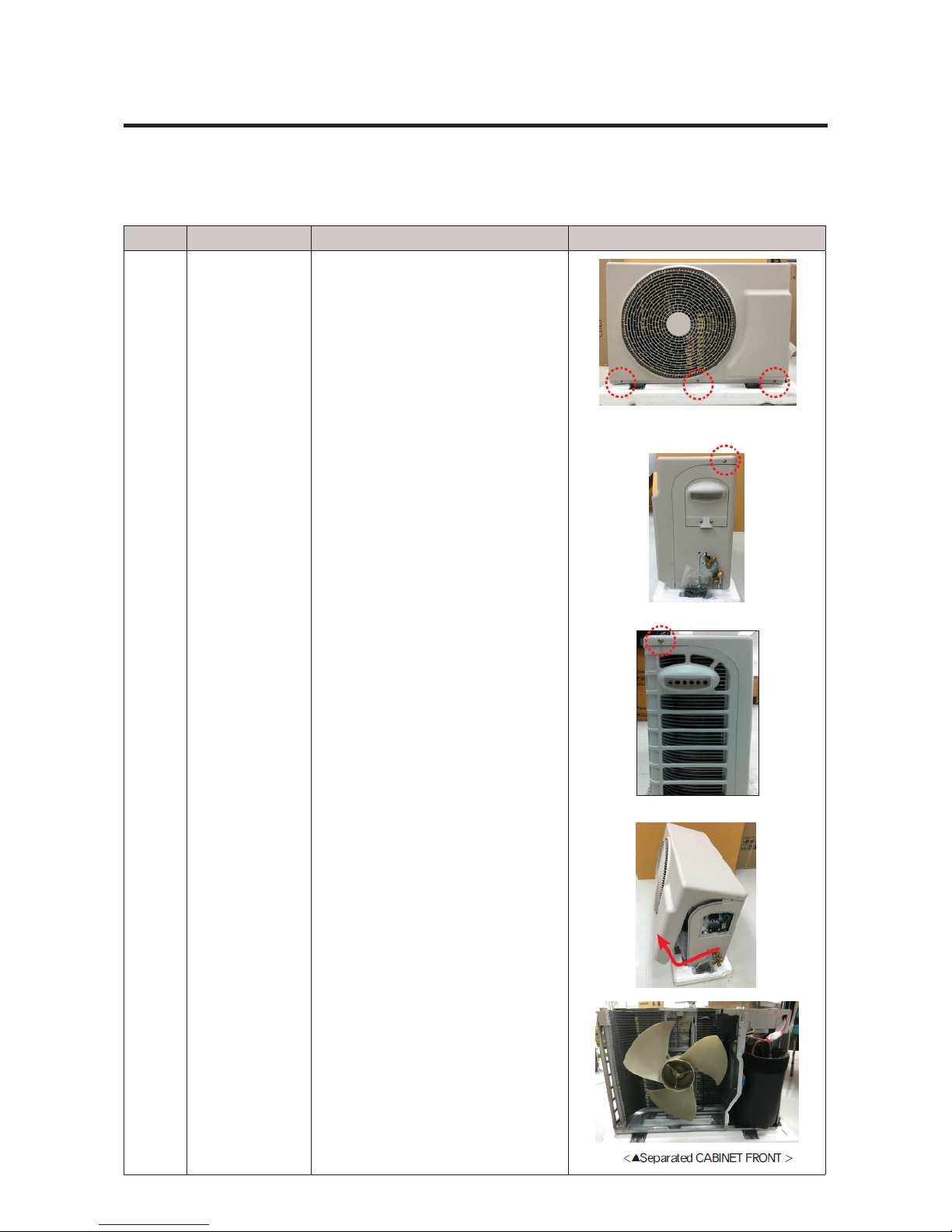
4-2. Outdoor Unit (N-V2MD)
AR09RXWXCWKXEU
AR12RXWXCWKXEU
NO. Parts Procedure Remark
1 Common Work 1) First, stop the operation of the air
conditioner, please cut off the supply
of power.
2) Please separate outdoor after
loosen the bottom screw 3EA of the
front three places. (+ screw driver
Use)
3) Please separate the positions of
the sides screw 1EA (+ screw driver
Use)
4) Please remove the portions of the
side screw 1. (+ screw driver Use)
5) Please separate lifting up and
grab the ends of the lower end of
the CABINET FRONT.
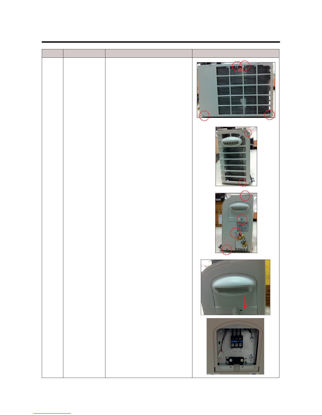
30
NO. Parts Procedure Remark
6) Please remove the screw 4ea
located on the rear panel.
(use + screwdriver)
7) Please separate the screw 2ea
located on the side panel.
(+ screw driver Use)
8) Please separate the screw 4ea
located on the side panel.
(+ screw driver Use)
9) Please remove the COVER
CONTROL OUT downward.
 Loading...