

Samsung AR12HSSDBWKNEU, AR12HSSDBWKXEU, AR09HSSFAWK, AR12HSSFAWK, AR09HSSFBWK Service Manual
...
AR09HSSFAWKNEU AR09HSSFAWKXEU
AR12HSSFAWKNEU AR12HSSFAWKXEU
AR09HSSFBWKNEU AR09HSSFBWKXEU
AR12HSSFBWKNEU AR12HSSFBWKXEU
AR12HSSFMWKNAX AR12HSSFMWKXAX
AR09HSSFAWKNEU
AR12HSSFAWKNEU
AR09HSSFBWKNEU
AR12HSSFBWKNEU
AR12HSSFMWKNAX
AR09HSSFAWKXEU
AR12HSSFAWKXEU
AR09HSSFBWKXEU
AR12HSSFBWKXEU
AR12HSSFMWKXAX
AR09HSSFAWK AR09HSSFAWK
AR12HSSFAWK AR12HSSFAWK
AR09HSSFBWK AR09HSSFBWK
AR12HSSFBWK AR12HSSFBWK
AR12HSSFMWK AR12HSSFMWK
Model:
Basic model:
AR12HSSDBWKNEU
AR12HSSDBWKXEU

Samsung Electronics 1
Contents
1. Precautions
·············································································································
1-1
1-1 Installing the air conditioner ·························································································································· 1-1
1-2 Power supply and circuit breaker ················································································································· 1-1
1-3 During operation ················································································································································ 1-1
1-4 Disposing of the unit ········································································································································· 1-2
1-5 Others ······································································································································································ 1-2
2. Product Specifications ······························································································· 2-1
2-1 The Feature of Product ····································································································································· 2-1
2-2 Product Specifications ······································································································································ 2-2
2-3 The Comparative Specifications of Product ····························································································· 2-3
2-4 Accessory and Option Specifications ········································································································· 2-4
3. Alignment and Adjustments ········································································ 3-1
3-1 Test Mode ······························································································································································· 3-1
3-2 Outdoor LED Display Error and Check Method ····················································································· 3-2
3-3 Setting Option Setup Method ······················································································································· 3-4
3-4 Setting Option Setup Method ······················································································································· 3-12
4. Disassembly and Reassembly ······································································ 4-1
4-1. Indoor Unit···························································································································································· 4-2
4-2. Outdoor Unit ························································································································································ 4-12
5. Control Exploded Views And Part List ························································ 5-1
5-2 ASSY Control In ·········································································································· ···································· 5-2
5-3 Assy Control Out ········································································································
········································ 5-3
6. Electrical Parts List ························································································ 6-1
6-1 INDOOR MAIN PCB (DB92-02873E) ············································· 6-1
6-2 INDOOR SUB PBA(DB92-02874A) ················································································································· 6-5
7. Wiring Diagram ······························································································ 7-1
7-1 Indoor Unit····························································································································································· 7-1
7-2 Outdoor Unit ························································································································································ 7-2
7-3 ASSY WIFI KIT ························································································································································ 7-3
5-1 WIFI Case································································································································································· 5-1
6-3 OUTDOOR MAIN PBA(DB92-02866A)-09K···················································
·············································· 6-6
····························································

2 Samsung Electronics
Contents
8. PCB Diagram ·································································································· 8-1
8-1 Indoor Unit····························································································································································· 8-1
8-2 Outdoor PCB ························································································································································ 8-2
8-3 Wire connecting the indoor unit terminal blocks ················································································· 8-3
9. Operating Instructions ·················································································· 9-1
9-1 Name of Each Part ·············································································································································· 9-1
9-2 Wireless Remote Control-Buttons and Display ······················································································· 9-2
10. Troubleshooting ·························································································· 10-1
10-1 Items to be checked first ······························································································································· 10-1
10-2 Communication Error ····································································································································· 10-2
10-3 PCB Inspection Method ································································································································· 10-37
10-4 ASSY WIFI KIT Inspection Method ············································································································· 10-39
11. Block Diagram ····························································································· 11-1
11-1 Indoor unit ·························································································································································· 11-1
11-2 Outdoor unit ······················································································································································· 11-2
12. Reference Sheet ··························································································· 12-1
12-1 Low Refrigerant Pressure Distribution ····································································································· 12-1
12-2 Pressure & Capacity mark ······························································································································ 12-1
12-3 Q & A for Non-trouble····································································································································· 12-2
12-4 Cleaning /Filter Change ································································································································· 12-5
12-5 Installation ··························································································································································· 12-6
12-6 Installation Diagram of Indoor Unit and Outdoor Unit ···································································· 12-7

Samsung Electronics 1-1
1. Precautions
1-1 Installing the air conditioner
O Uses should not install the air conditioner by themselves.
Ask the dealer or authorized company to install the air conditioner except window-type air conditioner in U.S.A and Canada.
O If you don't install the air conditioner properly, it may cause a fire, a water leakage or an electric shock.
O You must install the air conditioner according to the national wiring regulations and safety regulations.
O
Install the indoor unit higher than 2.5m from the floor to avoid the injury caused by the operation of the fan.
(except the window-type air conditioner)
O The manufacturer is not responsible for any accidents or injury caused by an incorrect installation.
O When installing the built-in type air conditioner, keep all electric cables such as the power cable and the connection cord in
pipes, ducts, or cable channels to protect them from the danger of impact or any other incidents.
1-2 Power supply and circuit breaker
O If the power cord of the air conditioner is damaged, it must be replaced by the manufacturer or a qualified person in order
to avoid a hazard.
O The air conditioner must be plugged into an independent circuit if applicable or connect the power cable to the auxiliary circuit
breaker.
An all pole disconnection form the power supply must be incorporated in the fixed wiring with a contact opening of>3mm.
O Do not extend an electric cord to the air conditioner.
O The air conditioner must be plugged in after you complete the installation.
1-3 During operation
O Do not repair the air conditioner at your discretion.
It is recommended to contact a service center directly.
O Never spill any kind of liquid on the air conditioner.
If this happens, turn off the air conditioner and contact an authorized service center.
O Do not insert anything between the airflow blades to prevent damage of the inner fan and consequent injury.
Keep children away from the air conditioner.
O Do not place any obstacles in front of the air conditioner.
O Do not spray any kind of liquid into the indoor unit. If this happens, turn off the air conditioner and contact a service center.
O Make sure that the air conditioner is well ventilated at all times.
Do not place a cloth or other materials over it.
O Remove the batteries if you don't use the remote control for a long time. (If applicable)
O Use the remote control within 7 meters from the indoor unit. (If applicable)

1-2 Samsung Electronics
1-4 Disposing of the unit
O Before the throwing out the air conditioner, remove the batteries from the remote control.
O When you dispose of the air conditioner, consult your dealer. If pipes are removed incorrectly, refrigerant may blow out
and cause air pollution. When it contacts with your skin, it can cause skin injury.
O The package of the air conditioner should be recycled or disposed of properly for environmental reasons.
1-5 Others
O Never store or load the air conditioner upside down or sideways to prevent the damage to the compressor.
O Young children or infirm persons should be always supervised when they use the air conditioner.
O Max current is measured according to IEC standard for safety.
O Current is measured according to ISO standard for energy efficiency.
Samsung Electronics 2-1
2. Product Specifications
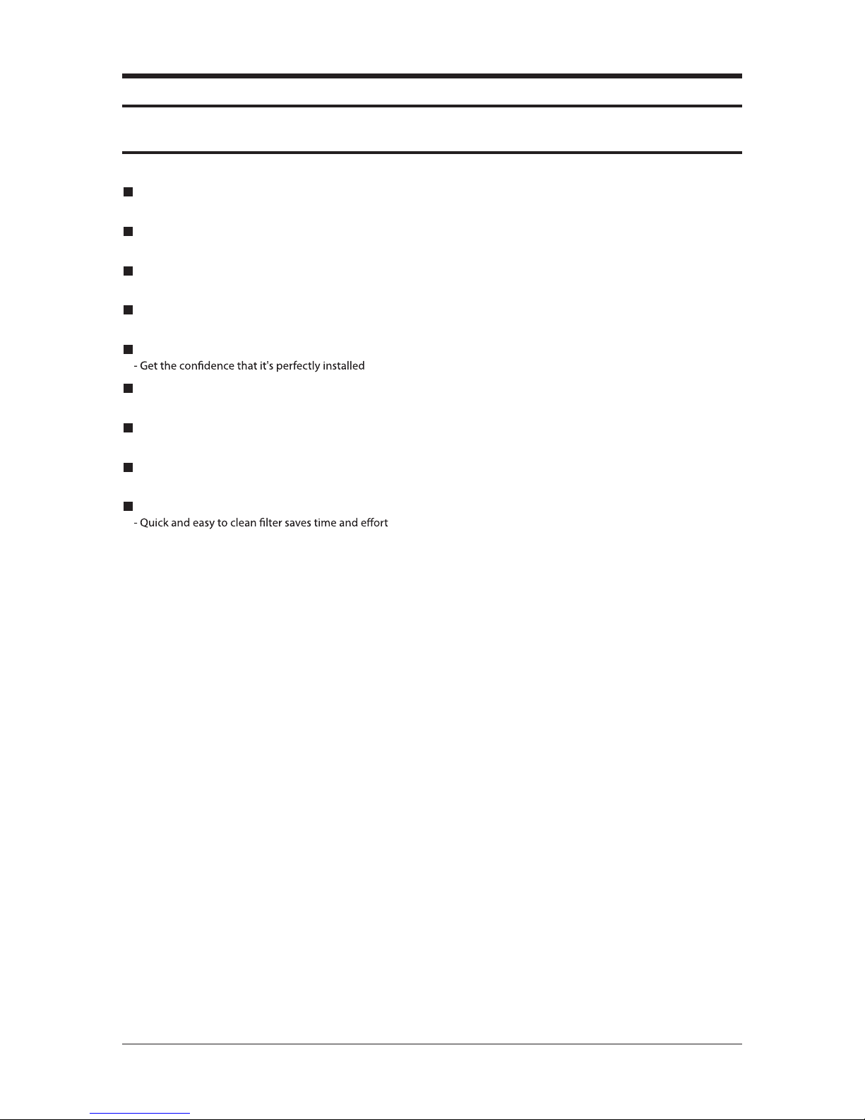
2-1 The Feature of Product
2 step cooling
- Get cool quickly and keep cool comfortably without shivering
Single user mode
- No worrying about the electricity bill, even using it when you're alone.
Crystal gloss design
- Uniquely stylish and innovative design to enhance your life and home
Smart Wi-Fi
- Control air conditioner anytime and anywhere
Smart Installation
Smart Check
- Don’t worry about the trouble-shooting in your home
Triple Protector Plus
- Use longer without damage in unsuitable conditions
Easy Installation
- Secure the easy Installation of Indoor unit and pipe connection
Easy Filter

2-2
Samsung Electronics
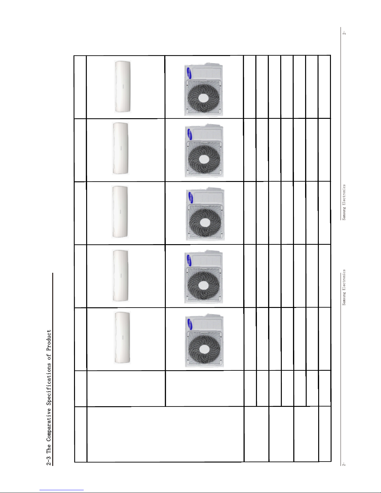
2-2 Product Specifications
Development
Model
Development
Model
Development
Model
Development
Model
Development
Model
AR09HSSFAWKNEU AR12HSSFAWKNEU AR09HSSFBWKNEU AR12HSSFBWKNEU AR12HSSFMWKNEU
W 220/550/780 220/940/1150 260/590/790 260/590/1150 220/880/1150
(low/std
/max)
180/750/1850 180/1050/2000 220/780/1550 220/1.05/1770 180/1000/2000
1.4/2.7/3.7 1.4/4.4/5.2 1.4/3.2/3.8 1.4/4.8/5.2 1.4/4.4/5.2
1.2/3.6/8.2 1.2/4.9/8.8 1.2/3.8/7 1.3/5.0/8.2 1.2/4.9/8.8
70/90/95 70/90/95 70/90/95 70/90/95 70/90/95
70/90/95 70/90/95 70/90/95 70/90/95 70/90/95
936*270*264 936*270*264 936*270*264 936*270*264 936*270*264
790*545*285 790*545*285 790*545*285 790*545*285 790*545*285
12.6 12.6 12.6 12.6 12.6
35.5 35.5 35.5 35.5 35.5
6.35 *7.5 6.35 *7.5 6.35 *7.5 6.35 *7.5 6.35 *7.5
9.52*7.5 9.52*7.5 9.52*7.5 9.52*7.5 9.52*7.5
D*L(mm) 20*550 20*550 20*550 20*550 20*550
2ROWx14STEPx635
+1ROWx10STEPx635
2ROWx14STEPx635
+1ROWx10STEPx635
2ROWx14STEPx635 2ROWx14STEPx635
2ROWx14STEPx635
+1ROWx10STEPx635
2ROWx24STEPx(850
+825)
2ROWx24STEPx(850
+825)
2ROWx24STEPx(850
+825)
2ROWx24STEPx(850
+825)
2ROWx24STEPx(850
+825)
g 1100 1100 1100 1100 1100
cc-----
CAPILARRY CAPILARRY CAPILARRY CAPILARRY CAPILARRY
ROTARY ROTARY ROTARY ROTARY ROTARY
UG9T115FUAEQSS UG9T115FUAEQSS UG9T115FUAEQSS UG9T115FUAEQSS UG9T115FUAEQSS
NONENONENONENONENONE
-----
-----
-56 -56 -56 -56 -56
-39 -39 -39 -39 -39
27ć or less 27ć or less 27ć or less 27ć or less 27ć or less
-15ć-24ć -15ć-24ć -15ć-24ć -15ć-24ć -15ć-24ć
-
-
-
-
-
-
-
-
Cooling Test Condition
Cooling Operating Condition
INDOOR
OUTDOOR
Heating Operating Condition
INDOOR
Air purifying system
Refrigerant Pipe
Liquid
mm*L(mm)
Gas
Drain Hose
Heat Exchanger
Indoor
Outdoor
Refrigerant
Freezer Oil Capacity
Refrigerant Control Unit
Compressor
Protection device(OLP)
Outer Dimension
Indoor
W*H*D(mm
)
Outdoor
Weight(net)
Indoor
Kg
Outdoor
-
Operating
Current
Cooling/Heating
(ISO)
A
Cooling/Heating
(SASO)
A
-
MODEL
ITEM
Power
Consumption
Cooling/Heating
(ISO)
Cooling/Heating
(SASO)
Power Factor
Cooling/Heating
%
3
3
MODEL AR09HSSFAWKNEU AR09HSSFBWKNEU AR12HSSFAWKNEU AR12HSSFBWKNEU AR12HSSFMWKNAX
Indoor Unit
Indoor Unit 12.6 11.9 12.6 11.9 11.9
Outdoor unit
35.5 35.5 35.5 35.5 35.5
Indoor Unit 936*270*264 936*270*264 936*270*264 936*270*264 936*270*264
Outdoor unit
790*545*285 790*545*285 790*545*285 790*545*285 790*545*285
Indoor Unit 43/56 43/56 45/58 44/58 45/43
Outdoor unit
51/59 51/59 55/62 53/62 53
Air Purifying System
Filter FULL HDFILTER FULL HDFILTER FULL HDFILTER FULL HDFILTER FULL HDFILTER
Design
Weight
Outer Dimension
Noise
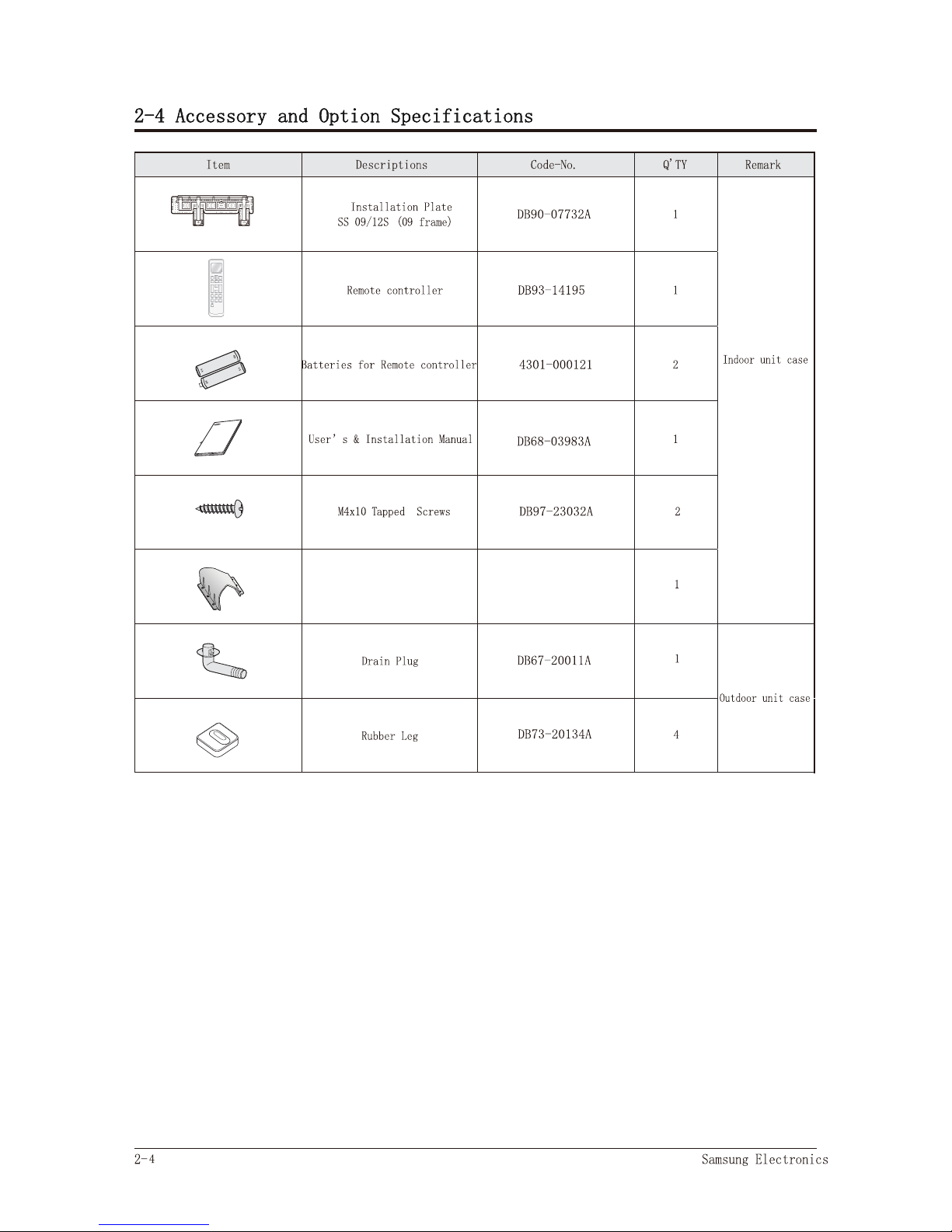
F
HOLDER
DB61-06187A

Samsung Electronics 3-1
3. Alignment and Adjustments
3-1 Test Mode
How to Approach Test Mode
You can approach the test mode by pressing the on/off switch of
indoor unit for 5 seconds.
Test mode operation option
After installing the air conditioner, check whether each subordinate is normally operated or not by operating the test mode.
ƽ
When an Error occurs, display the Error Mode.
ƽ
Operation Mode : Cool mode. operate the cool mode by operating the compressor by force without the compressor ON/OFF
according to the set temperature/indoor temperature. (Do not follow the antifreezecontrol)
ƽ
Up-down louver : Up-down swing mode
ƽ
Indoor Fan : Turbo
ƽ
Because the teat mode operate the cool mode by force not related to the set temperature / indoor
temperature, check whether each subordinate is operated normally or not after completing installation
and must turn off the power of the air conditioner.
Note
3-2 Samsung Electronics
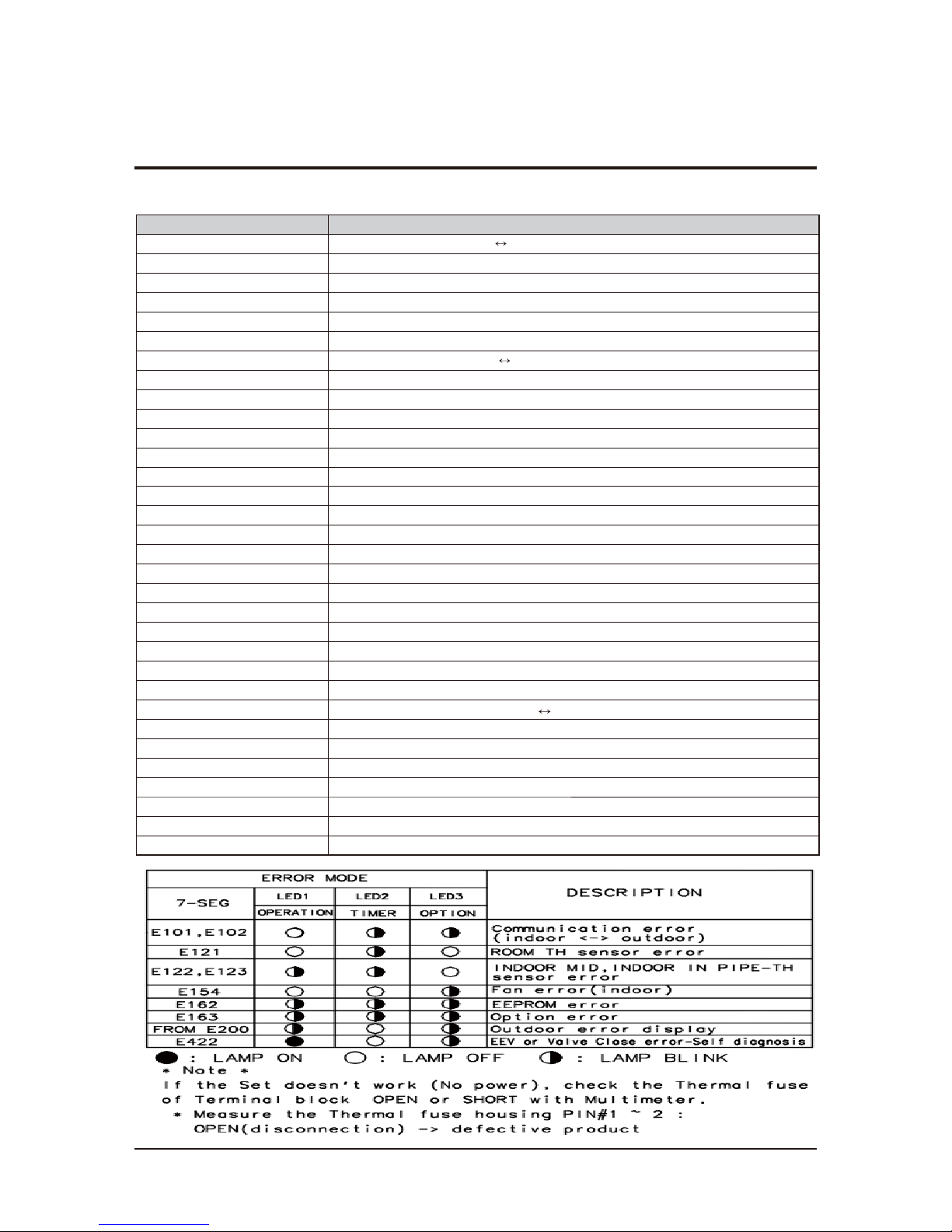
3-2 Display Error and Check Method
3-2-1 Indoor Display Error and Check Method
NOITPIRCSEDEDOMRORRE
E101 / E102
Communication Error (Indoor Outdoor)
E121
ROOM TH sensor error
E122
INDOOR MID, INDOOR IN PIPE-TH sensor error
E154
Fan Error (Indoor)
E162
EEPROM Error (Indoor)
E163
Option Error
E203
Time out Comm. (Inv Micom
Main Micom)
E221
OUT-TH(Outdoor Temperature) Sensor Error
E231
CON-TH(Cond Temperature) Sensor Error
E251 DIS-TH(Discharge Temperature) Sensor Error
E416 DIS-TH(Discharge Temperature) Over Error
E422 EEV or Valve Close error-Self diagnosis
E440 Prohibit Operation Condition Error (Heating)
E441 Prohibit Operation Condition Error (Cooling)
E458 Fan Error(Outdoor)
E461 Comp Starting Error
E462 AC Input I_Limit Trip Error
E464 IPM Over Current(O.C) Error
E465 Comp V_limit/I_limit Error
E466 DC-Link Voltage Under/Over Error
E467 Comp Wire Missing Error
E468 Current Sensor Error
E469 DC-Link Voltage Sensor Error
E470 EEPROM Data Error (no data)
E471
EEPROM Data Error (Main Micom
Inv Micom)
E474 Heatsink Sensor Error
E483 Over Voltage Protection Error
E484 PFC Over Load Error
E485 Input Current Sensor Error
E488 AC Input Voltage Sensor Error
E500 Heatsink Over Temperature Error
E554 Gas Leak Error
Samsung Electronics 3-3
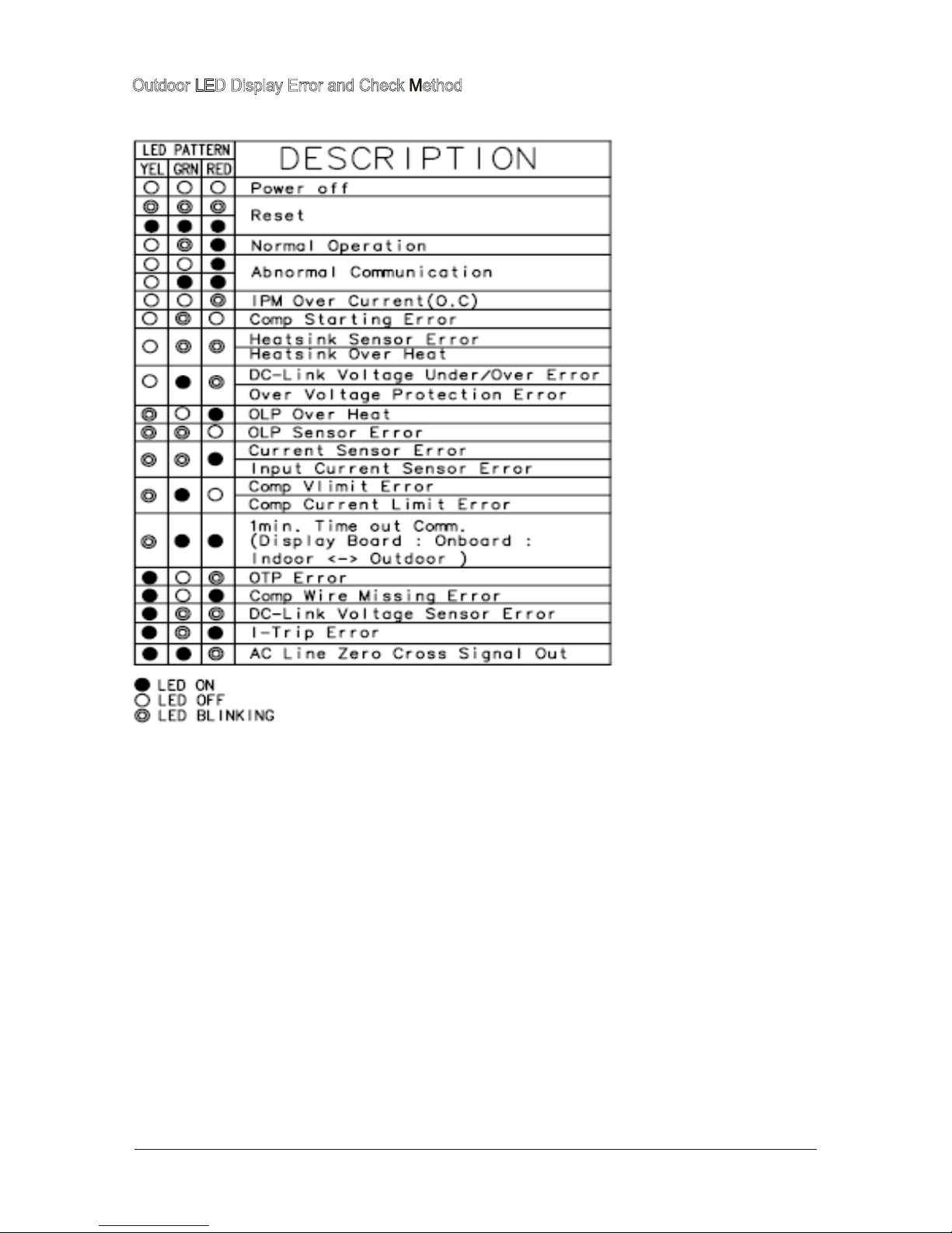
Outdoor LED Display Error and Check Method
Samsung Electronics 3-4
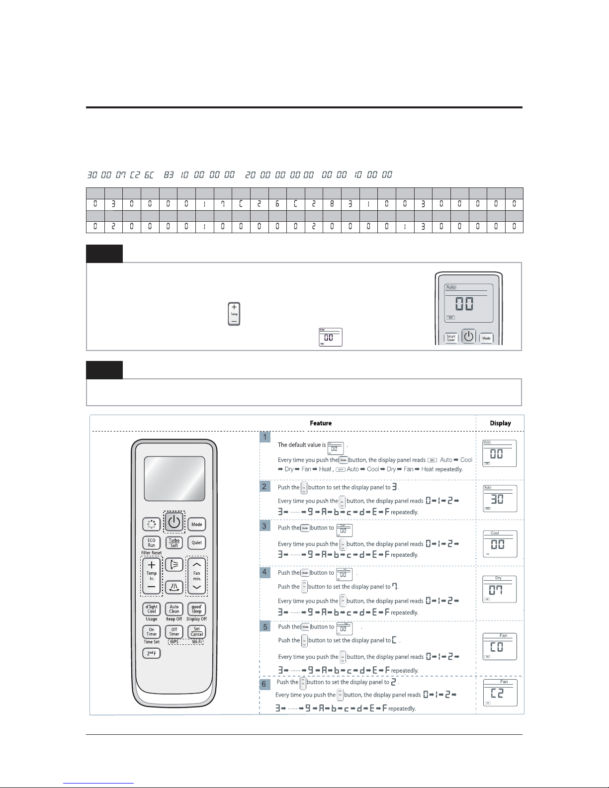
3-3 Setting Option Setup Method(AR09(12)HSSFA(B)WK/EU)
Step 2
Enter the Options Setup mode and select your options asscording to the following procedure.
ex) Option No. :
Note :
SEG1, SEG7, SEG13, SEG19 need not to be pressed in, so in fact the Option No. we should press in is as below.
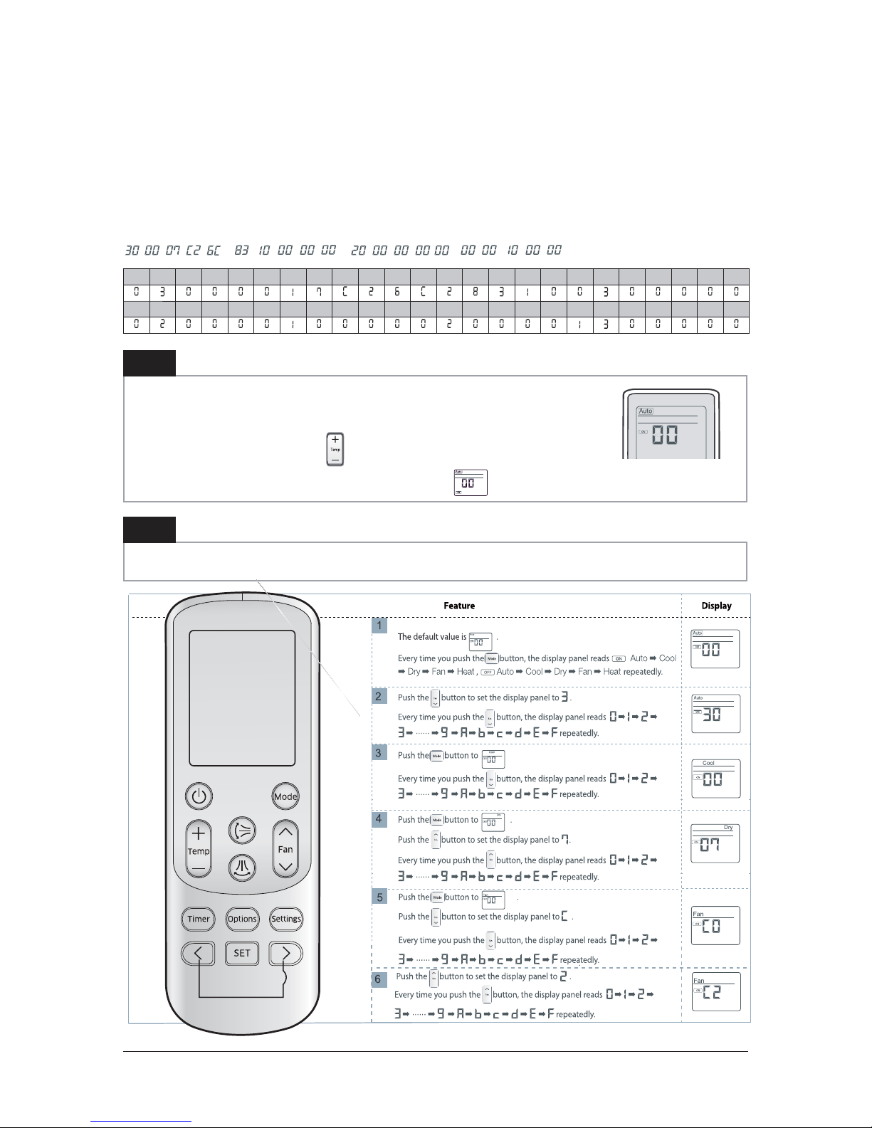
Step 1
Enter the Option Setup mode.
1. Tack out the batteries of remote control.
2. Press the temperature button simultaneously and insert the battery again.
3. Make sure the remote control display shown as .
SEG1 SEG2 SEG3 SEG4 SEG5 SEG6 SEG7 SEG8 SEG9 SEG10 SEG11 SEG12 SEG13 SEG14 SEG15 SEG16 SEG17 SEG18 SEG19 SEG20 SEG21 SEG22 SEG23 SEG24
SEG25 SEG26 SEG27 SEG28 SEG29 SEG30 SEG31 SEG32 SEG33 SEG34 SEG35 SEG36 SEG37 SEG38 SEG39 SEG40 SEG41 SEG42 SEG43 SEG44 SEG45 SEG46 SEG47 SEG48

3-5 Samsung Electronics
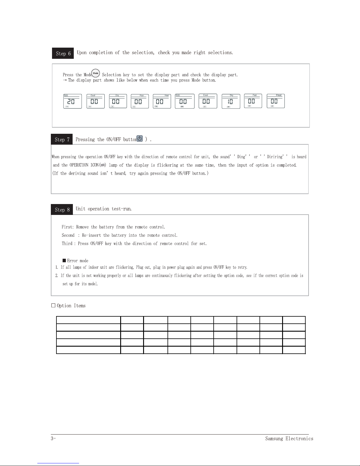
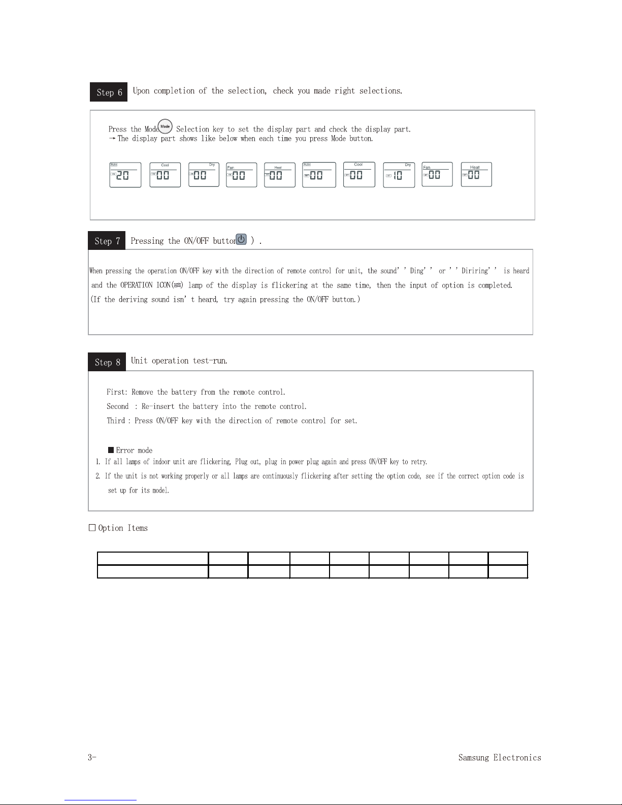
Step 4
Pressing the ON/OFF button ( ).
When pressing the operation ON/OFF key with the direction of remote control for unit, the sound ’’Ring’’ or ’
and the OPERATION ICON(
) lamp of the display is flickering at the same time, then the input of option is completed.
(If the deriving sound isn’t heard, try again pressing the ON/OFF button.)
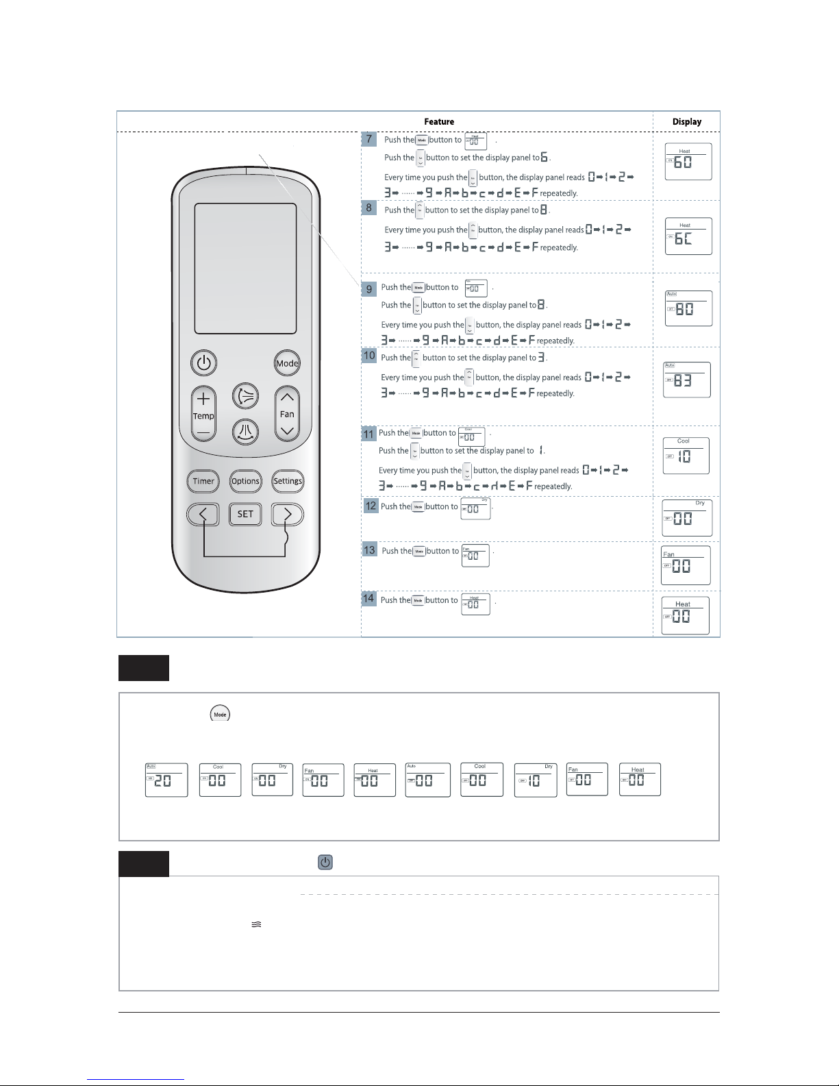
Press the Mode Selection key to set the display part and check the display part.
ė
The display part shows like below when each time you press Mode button.
Step 3
Upon completion of the selection, check you made right selections.

Samsung Electronics 3-6
Step 1 (Enter the Option Setup mode) is executed.
(Seg25 ~ 48 for setting remote control Setup)
Push the
Mode button to set the display panerl to 2.
Every time you push the
button, the display panel reads
...
repeatedly.
Push the Mode button to set the display panerl to 1.
Every time you push the
button, the display panel reads
...
repeatedly.
Step 5
Enter the Options Setup mode and select your options asscording to the following procedure.
Model 1~6 7~12 13~18 19~24 49~54 55~60 61~66 67~72
AR09HSSFAWK/EU 012045 156A4A 271920 372937 033E3B 102432 200000 300000
AR09HSSFBWK/EU 012045 166A6B 272338 372B35 034744 10393E 200000 300000
AR12HSSFAWK/EU 012045 156A6B 272328 372A37 034645 10383E 200000 300000
AR12HSSFBWK/EU 012045 166A4A 271920 372A35 03403B 102432 200000 300000
7
Samsung Electronics 3-8
Setting Option Setup Method(AR12HSSFMWK/AX)
Step 2
Enter the Options Setup mode and select your options asscording to the following procedure.
ex) Option No. :
Note :
SEG1, SEG7, SEG13, SEG19 need not to be pressed in, so in fact the Option No. we should press in is as below.
Step 1
Enter the Option Setup mode.
1. Tack out the batteries of remote control.
2. Press the temperature button simultaneously and insert the battery again.
3. Make sure the remote control display shown as .
SEG1 SEG2 SEG3 SEG4 SEG5 SEG6 SEG7 SEG8 SEG9 SEG10 SEG11 SEG12 SEG13 SEG14 SEG15 SEG16 SEG17 SEG18 SEG19 SEG20 SEG21 SEG22 SEG23 SEG24
SEG25 SEG26 SEG27 SEG28 SEG29 SEG30 SEG31 SEG32 SEG33 SEG34 SEG35 SEG36 SEG37 SEG38 SEG39 SEG40 SEG41 SEG42 SEG43 SEG44 SEG45 SEG46 SEG47 SEG48
3-9 Samsung Electronics
Step 4
Pressing the ON/OFF button ( ).
When pressing the operation ON/OFF key with the direction of remote control for unit, the sound ’’Ding’’ or ’
and the OPERATION ICON(
) lamp of the display is flickering at the same time, then the input of option is completed.
(If the deriving sound isn’t heard, try again pressing the ON/OFF button.)
Press the Mode Selection key to set the display part and check the display part.
ė
The display part shows like below when each time you press Mode button.
Step 3
Upon completion of the selection, check you made right selections.

Samsung Electronics 3-10
Step 1 (Enter the Option Setup mode) is executed.
(Seg25 ~ 48 for setting remote control Setup)
Push the
Mode button to set the display panerl to 2.
Every time you push the
button, the display panel reads
...
repeatedly.
Push the Mode button to set the display panerl to 1.
Every time you push the
button, the display panel reads
...
repeatedly.
Step 5
Enter the Options Setup mode and select your options asscording to the following procedure.
Model 1~6 7~12 13~18 19~24 49~54 55~60 61~66 67~72
AR12HSSFMWK/AX 012045 156A6B 272328 372A34 034645 10383E 200000 300000
11
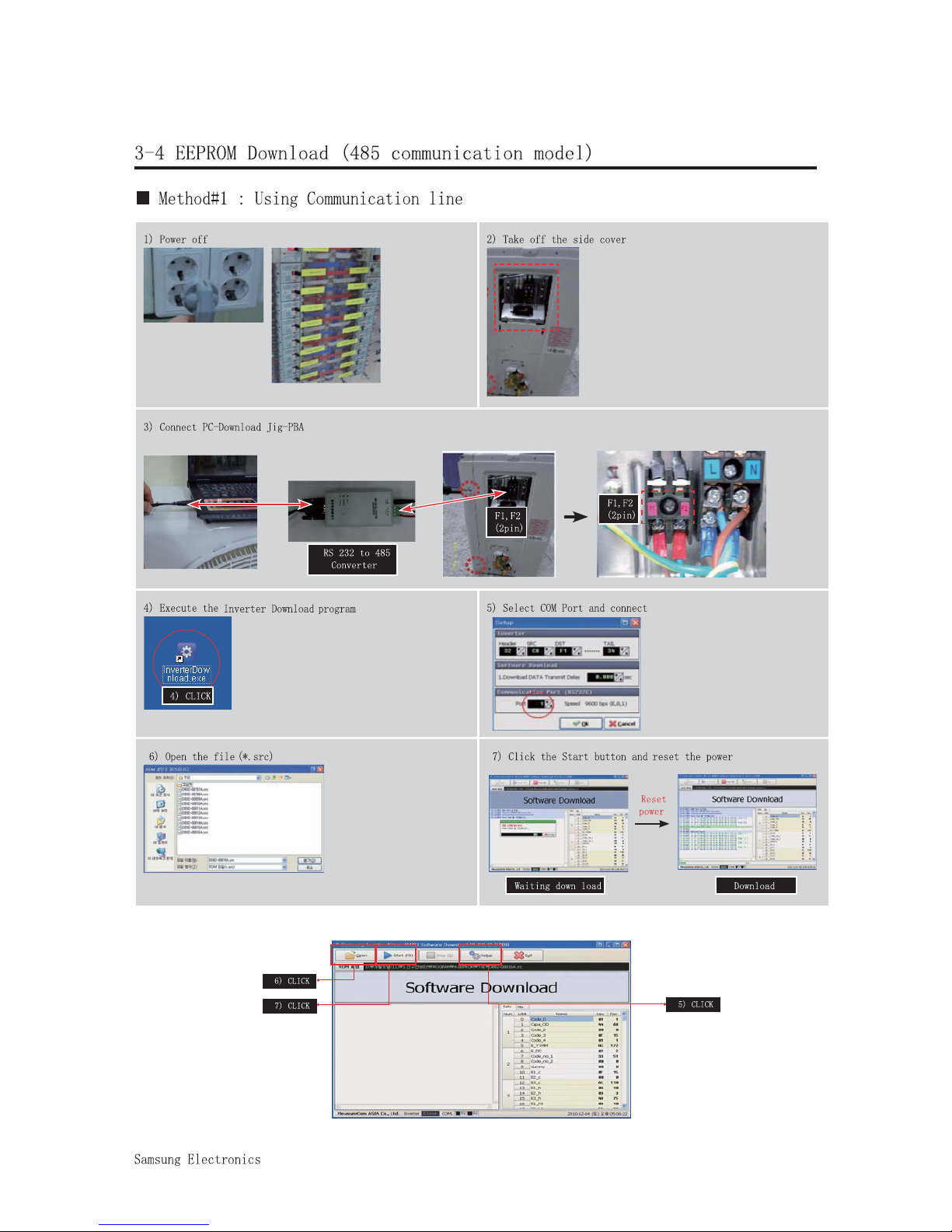
3-12

Download connector
(10pin)
3-13

Samsung Electronics 4-1
4. Disassembly and Reassembly
Q Necessary Tools
Item Remark
+SCREW DRIVER
MONKEY SPANNER
- SCREW DRIVER

4-2 Samsung Electronics
No Parts
krameRerudecorP
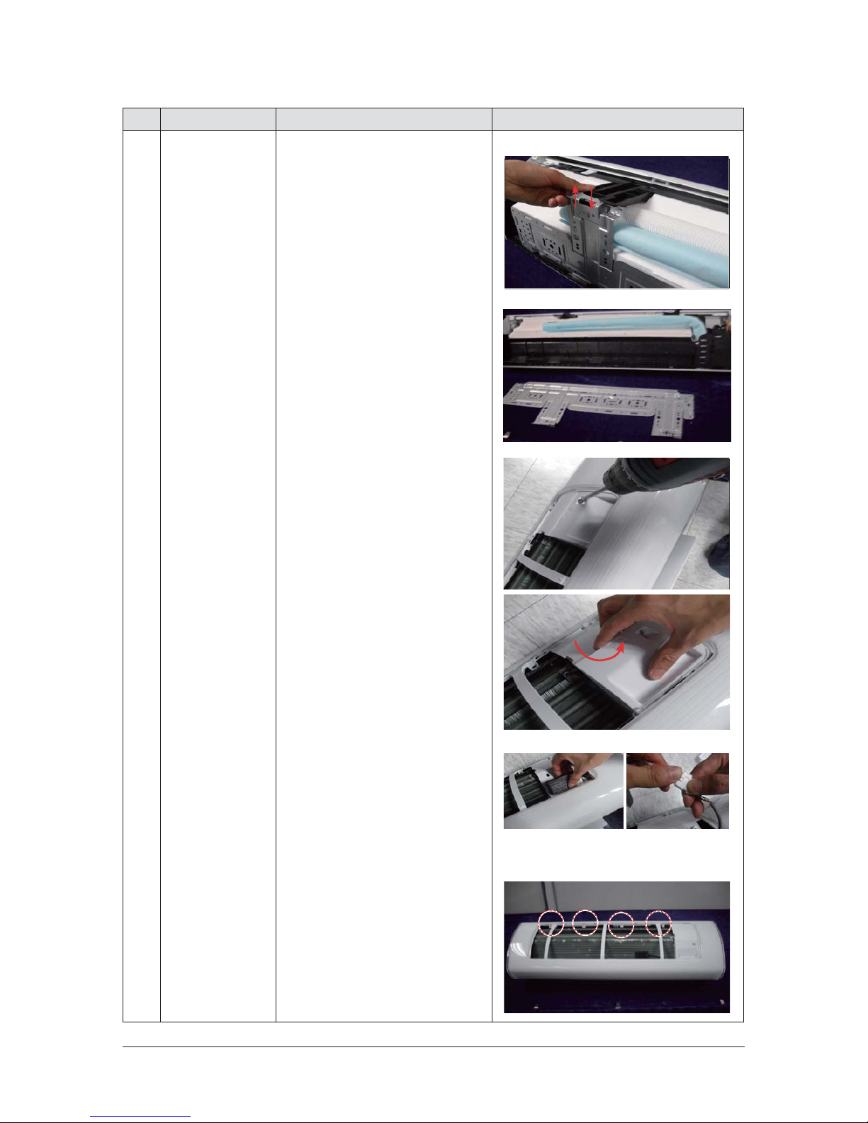
1 PANEL-FRONT 1) Stop the driving of air conditioner
and shut off
main power supply.
2) Detach FILTER PRE from the PANEL
FRONT.
3) Cover Panel is assembled on bottom
of indoor
unit as shown in the figure.
Remove the Cap Screw as shown on the
right
side and then remove the screw
the Cover Panel.
4-1. Indoor Unit
and seperate

Samsung Electronics 4-3
No Parts
krameRerudecorP
4) Cover Panel is fixed to body by Hook
in center
area and side area.
5) Separate the hook after pushing both
end of
Cover Panel as shown in the figure.
(Watch out for the damage of the hook)
6) Raise front part upward obliquely
as shown in
the figure and then remove
Center area
Side area
Side area
HOOK
the hooks.

4-4 Samsung Electronics
No Parts
krameRerudecorP
Caution:
Assembly of Cover Panel after service end.
-
Reassembly is in the reverse order
of the
removal.
- Piping and drain hose must be careful not to
damage and Progress must be done with
both
hands.
Hook (Side)
Hook (Center)
Screw
Cap Screw

4-5 Samsung Electronics
No Parts
krameRerudecorP
˅
Door is assembled to the panel front
by
Take
Remove the two screws as
in the figure.
out of the
two screws.
shown
cover
two screws mocha-left and right
in the correct direction.Get out of
the door in the figure.Remove the
screw and seperate hanger.
4-6 Samsung Electronics
No Parts
krameRerudecorP
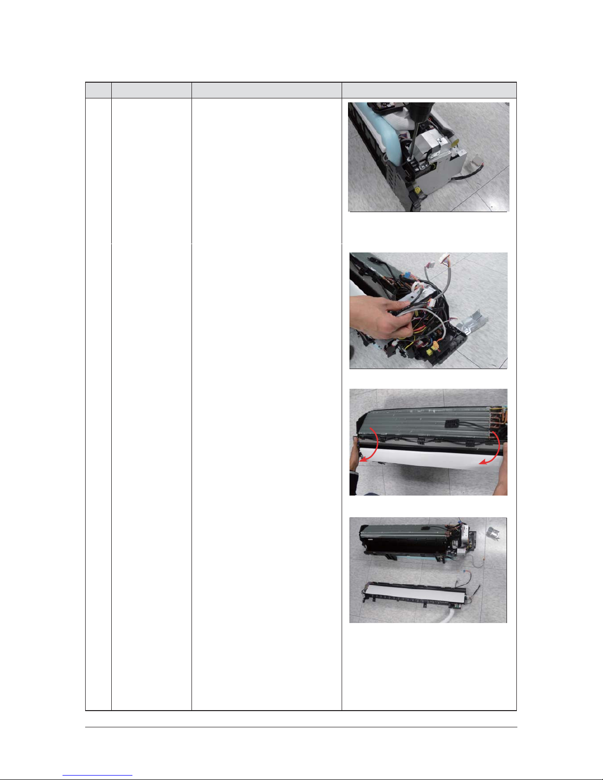
8)
Use the drive to remove the screw of
cover panel-sub. Take out of cover
panel-sub.
9) To detach the COVER-PANEL from the main
frame, loosen 4 HOOK Structures.
When separate the hook :
Use the (-) screw Driver.
(-)Screw Driver Insert the hook and
then pull the
right side.
hook as shown on the
(Watch out for the damage of the hook)

4-7 Samsung Electronics
No Parts
krameRerudecorP
4-8 Samsung Electronics
No Parts
krameRerudecorP
2 TRAY DRAIN 1) Before detaching TRAY-DRAIN from the
main frame,you should detach assy
plate-control first and seperate the
connecting line.
Pull the bottom of the TRAY DRAIN
towards you.
 Loading...