

Samsung AQV18UGAN, AQV24UGAN, AQV18EWAN, AQV24EWAN, AQV24EWAX Service Manual
...
SPLIT-TYPE AIR CONDITIONER
INDOOR UNIT OUTDOOR UNIT
Basic : AQV18UGAN
AQV24UGAN
Model
: AQV18EWAN
AQV24EWAN
Model Code : AQV18EWAX
AQV18EWAN
AQV24EWAN
AIR CONDITIONER THE FEATURE OF PRODUCT
AQV24EWAX
S.INVERTER
AQV18EWAN
AQV24EWAN
AQV18EWAX
AQV24EWAX
Air Conditioner
Mode
Mode can help you sleep quickly and
soundly and wake up refreshed.
Silence Mode
ncuoy,"edoMecneliS"ehtesuuoynehW
experience extremely quiet operation of your
air conditioner.
Refer to the service manual in the GSPN(see the rear cover) for the more information.

Contents
Operating Instructions and Installation
11. Precautions
1-1 Precautions for the Service
1-2 Precautions for the Static Electricity and PL
1-3 Precautions for the Safety
12. Product Specifications
2-1 The Feature of Product
2-1-1 The Feature of Product
2-1-2 Modified items compared with Basic model
2-1-3 New components to be applied
2-2 The Comparative Specifications of Product
2-3 Accessory and Option Specifications
2-3-1 Accessories
13. Disassembly and Reassembly
3-1 Indoor Unit
3-2 Outdoor Unit
14. Troubleshooting
4-1 Setting Option Setup Method
4-2 Display Error and Check Method
4-2-1 Display Error mode
4-3 Fault Diagnosis by Symptom
4-3-1 Communication error When E101 or E102 is displayed
4-3-2 Indoor Temperature Sensor ErrorWhen is diplayed
4-3-3 Indoor Heat Exchanger Temperature Sensor ErrorWhen is diplayed
4-3-4 Indoor Fan Motor Speed Detecting ErrorWhen is diplayed
4-3-5 MPI ErrorWhen E186 is displayed
4-3-6 Outdoor temperature sensor error When E221 is displayed............................................ 4-11
4-3-7 Coll temperature sensor error When E237 is displayed...................................................... 4-12
4-3-8 Discharge temperature sensor error When E251 is displayed.......................................... 4-13
4-3-9 Discharer over termperature sensor error When E416 is displayed................................ 4-14
4-3-10 The outdoor unit fan error When E458 is displayed............................................................. 4-15
4-3-11 Compressor start error When E461 is displayed..................................................................... 4-16
4-3-12 I_Trip err
4-3-13 O.C.(over current)error When E464 is displayed..................................................................... 4-18
4-3-14 Comp Rotation error When E467 is displayed........................................................................ 4-19
4-3-15 Current sensor error When E468 is displayed......................................................................... 4-20
4-3-16 DC-Link voltage sensor error When E469 is displayed........................................................ 4-21
4-3-17 OTP error When E471 is displayed............................................................................................... 4-22
........................................................................................................................................
.............................................................................................................
................................................................................
...............................................................................................................
...............................................................................................................
....................................................................................................................
...........................................................................................................
.....................................................................
..........................................................................................
................................................................................
...........................................................................................
...............................................................................................................................
..............................................................................................
.........................................................................................................................................
.....................................................................................................................................
............................................................................................................................
.......................................................................................................
..................................................................................................
.................................................................................................................
........................................................................................................
......................................
.......................................
.........................
...................................................................................
or When E462 is displayed........................................................................................... 4-17
.........
1-1
1-1
1-1
1-2
2-1
2-1
2-1
2-2
2-2
2-3
2-4
2-4
3-1
3-2
3-10
4-1
4-1
4-4
4-4
4-6
4-6
4-7
4-8
4-9
4-10
Samsung Electronics 1
Operating Instructions and Installation
Contents
4-3-18 AC Line Zero Cross signal out error When E472 is displayed
4-3-19 Operation condition secession error When E400/441 is displayed.............................. 4-23
4-3-20 Capacity miss match error When E556 is displayed........................................................... 4-23
4-3-21 DC-Link voltage under/over error When E466 is displayed............................................. 4-24
4-3-22 No Power (completely dead)-Initial diagnosis (Not displayed)
4-3-23 The outdoor unit power supply error (Not displayed)............................................................ 4-26
4-3-24
4-3-25 When the remote control is not receiving
4-4 PCB Inspection Method
4-4-1 Pre-inspection Notices ............................................................................................................................. 4-29
4-4-2 Inspection Procedure ............................................................................................................................... 4-29
4-4-3 Indoor Detailed Inspection Procedure ............................................................................................. 4-29
4-4-4 Outdoor Detailed Inspection Procedure.......................................................................................... 4-30
4-5 Main Part Inspection Method
15. Exploded Views and Parts List
5-1 Indoor Unit
5-2 Outdoor Unit
5-3 Ass'y control in ................................................................................................................................................. 5-5
5-4 Ass'y control out ................................................................................................................................................. 5-7
16. Elecrtical Parts List
17. Wiring Diagram
7-1 Indoor Unit
7-2 Outdoor Unit
When the Up/Down Louver Motor Does Not Operate. (Initial Diagnosis) (Not displayed)
........................................................................
..................................................................................................................
........................................................................................................
.............................................................................................
.........................................................................................................................................
.....................................................................................................................................
...................................................................................................
..............................................................................................................................
.........................................................................................................................................
.....................................................................................................................................
....................................
.....................................
....
4-22
4-25
4-27
4-28
4-29
4-31
5-1
5-1
5-3
6-1
7-1
7-1
7-2
10-4
11
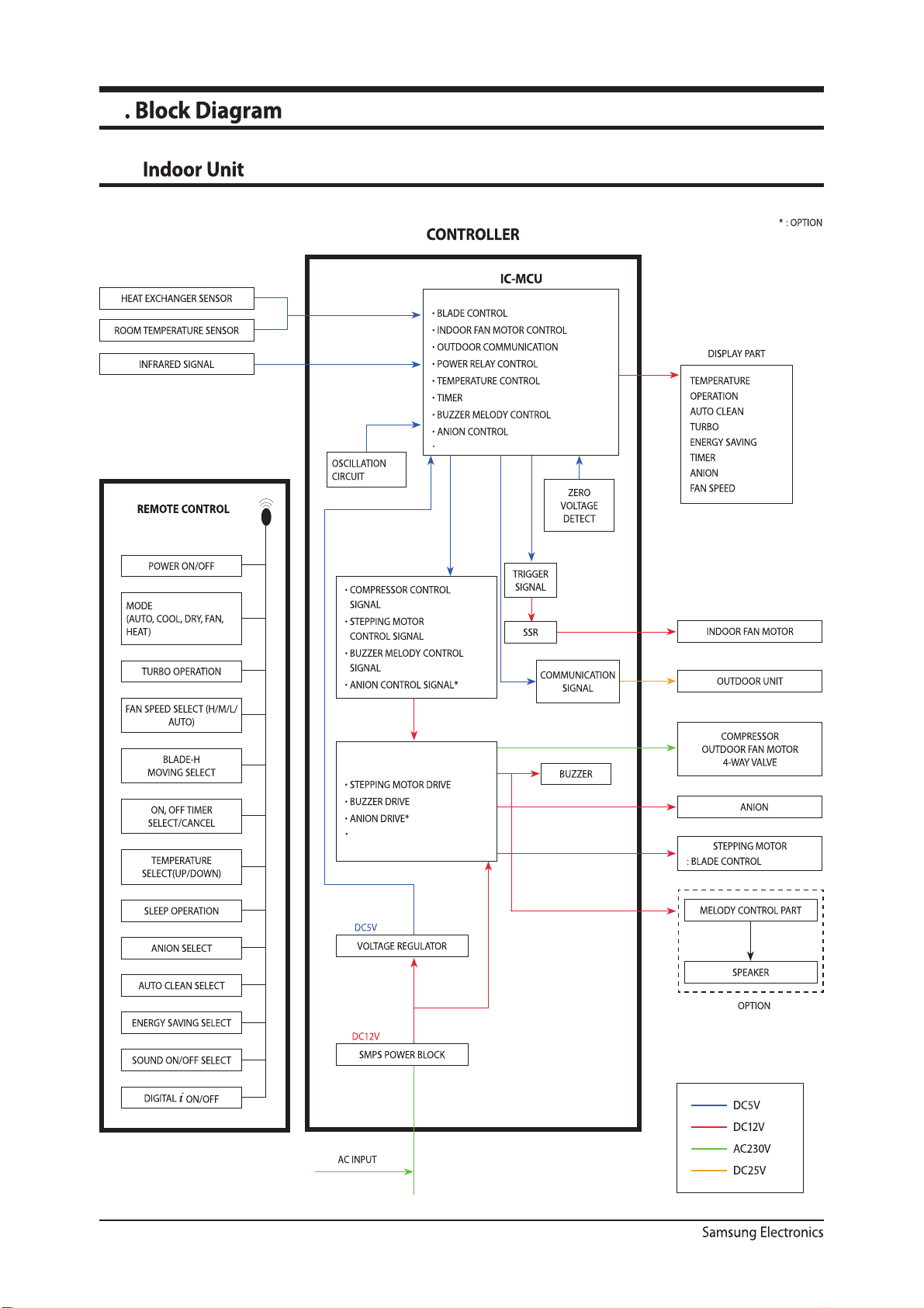
11-1
11-2
12
12-1
12-2
12-3
12-4
12-5
12-6
12-7
2 Samsung Electronics
11-2
12-1
12-1
12-2
12-3
12-4
12-7
12-9
12-10
11
11-1
HUMDITY CONTROL
11-1
MPI DRIVE
11-2
11-2
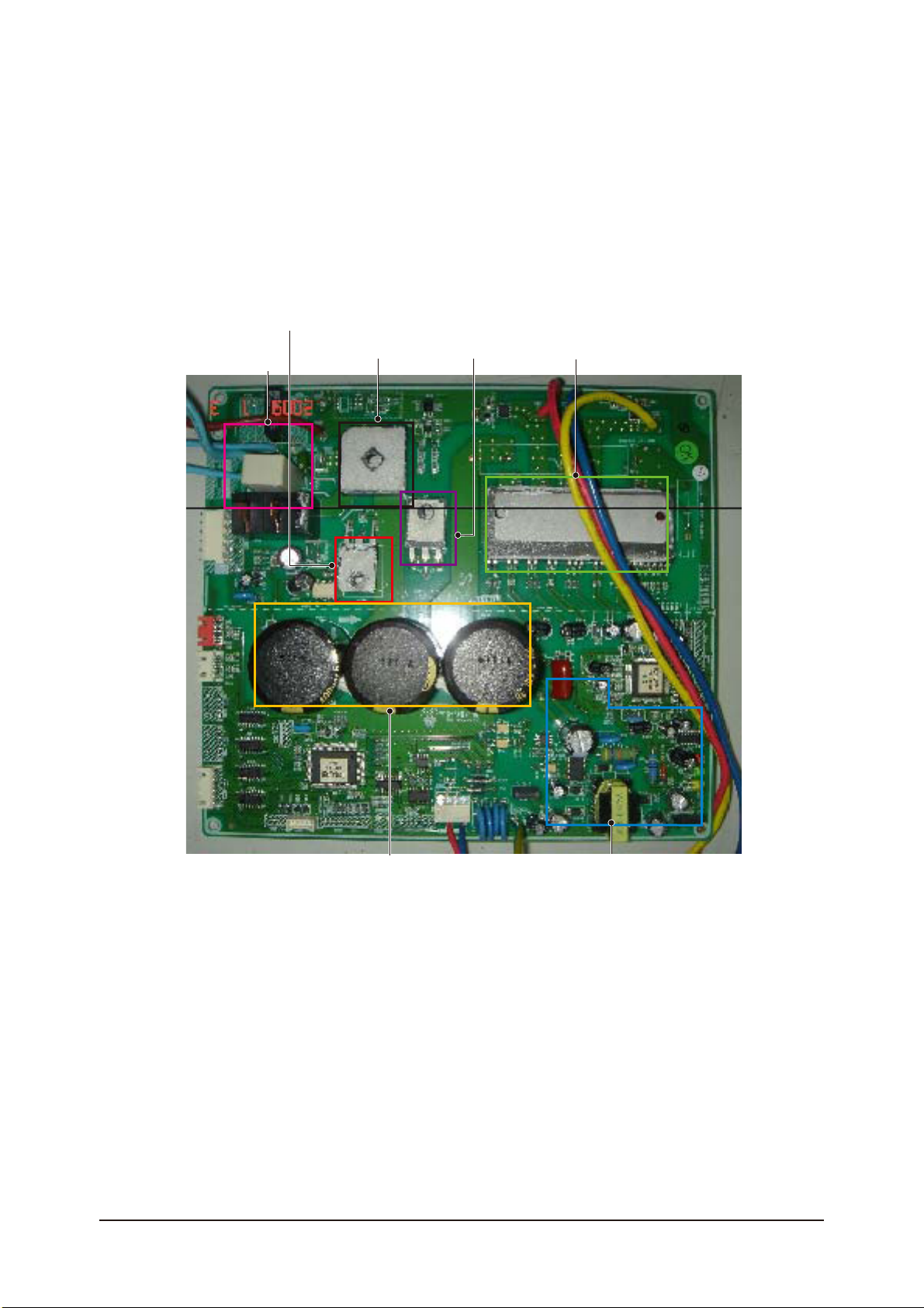
IGBT
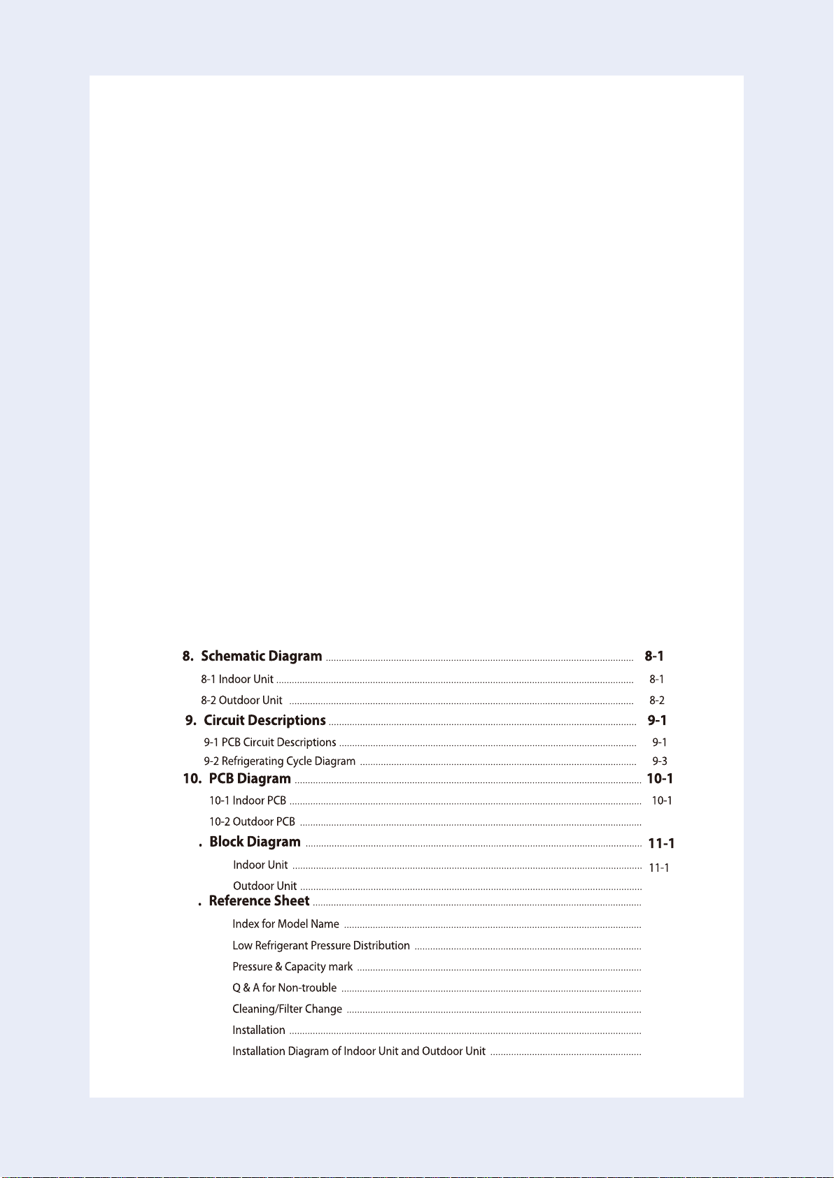
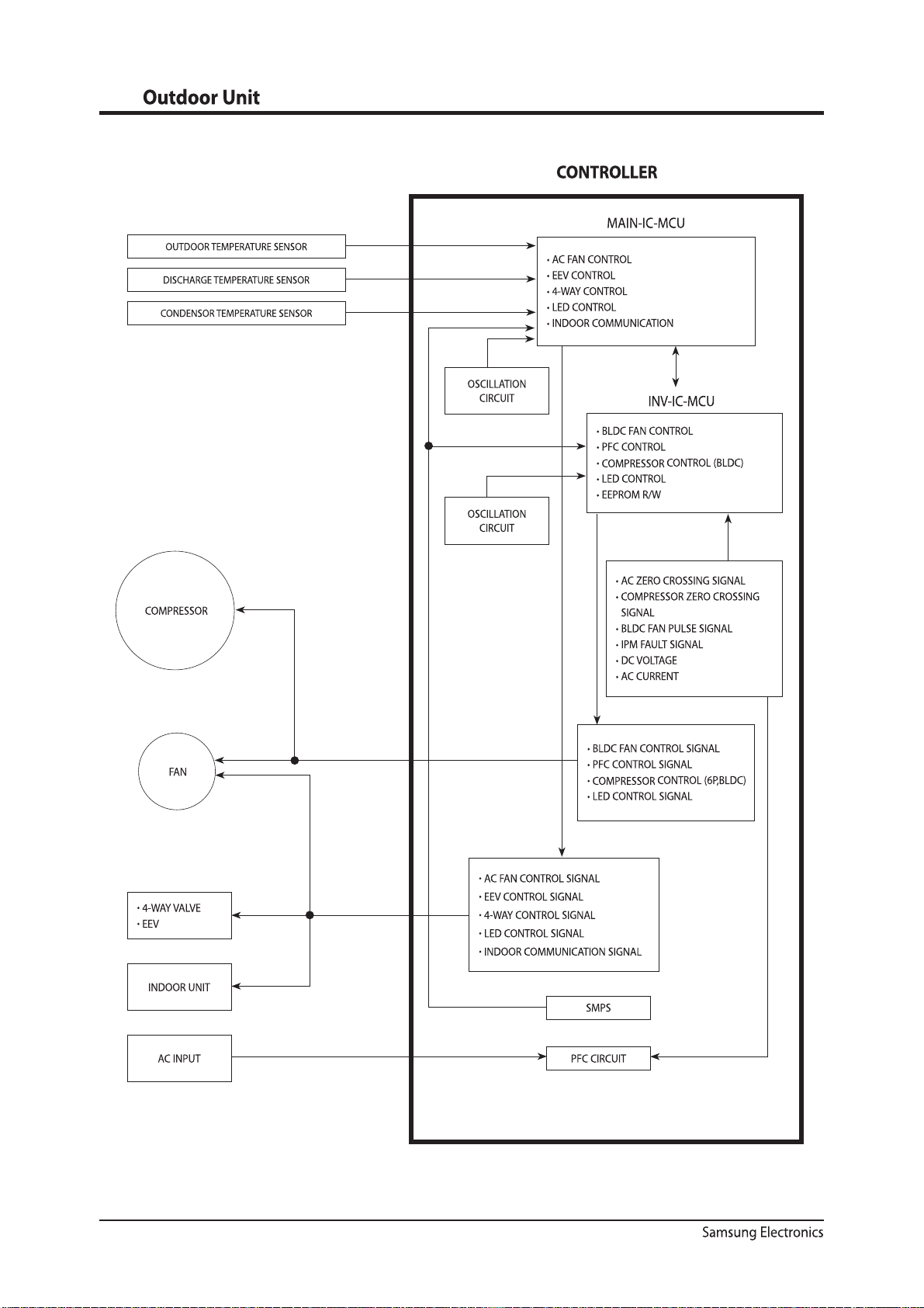
Block Diagram
OUTDOOR FAN
B/D
DIODE
IPM
Samsung Electronics
DC_LINK CAP
SMPS
11-3
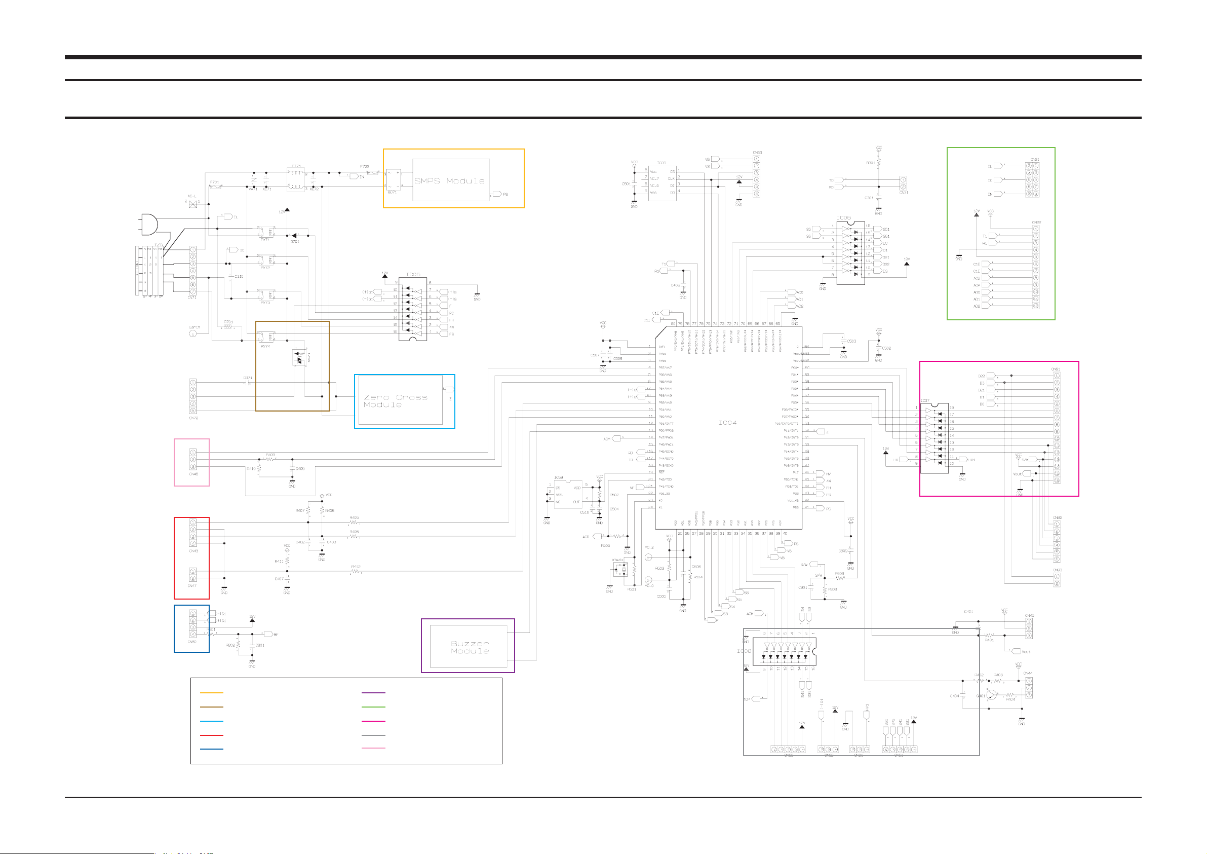
$JSDVJU%FTDSJQUJPOT
1$#$JSDVJU%FTDSJQUJPOT
*OEPPS6OJU
4.141"35
*/%003'"/$0/530-
;&30$3044*/(1"35
*/%0035&.1&3"563&4&/403
.1*1"35
#6;;&31"35
46#1$#$0//&$503
%*41-":1"35
45&1.0503*0/
)6.*%1"35
5IJT%PDVNFOUDBOOPUCFVTFEXJUIPVU4BNTVOHTBVUIPSJ[BUJPO
4BNTVOH&MFDUSPOJDT
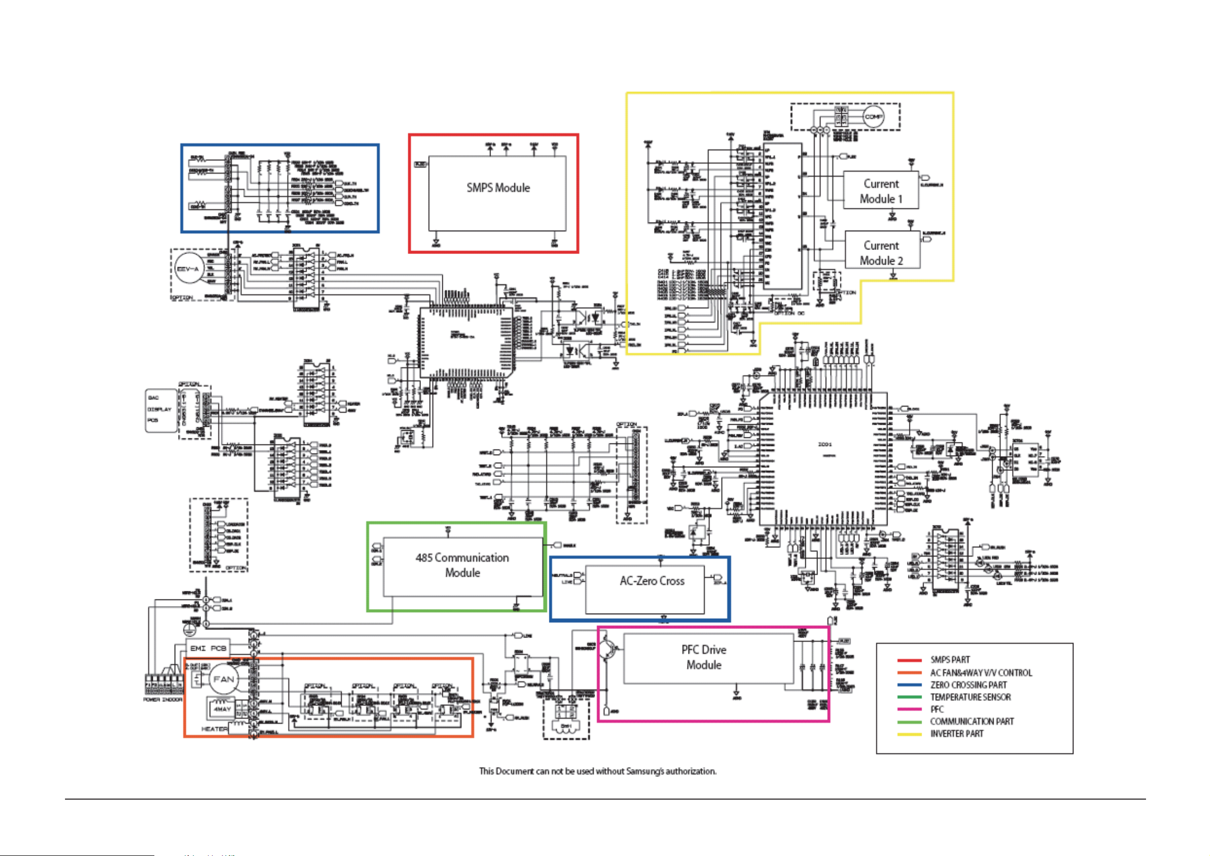
Circuit Descriptions Circuit Descriptions
9-1-2 Outdoor Unit
Samsung Electronics 9-2
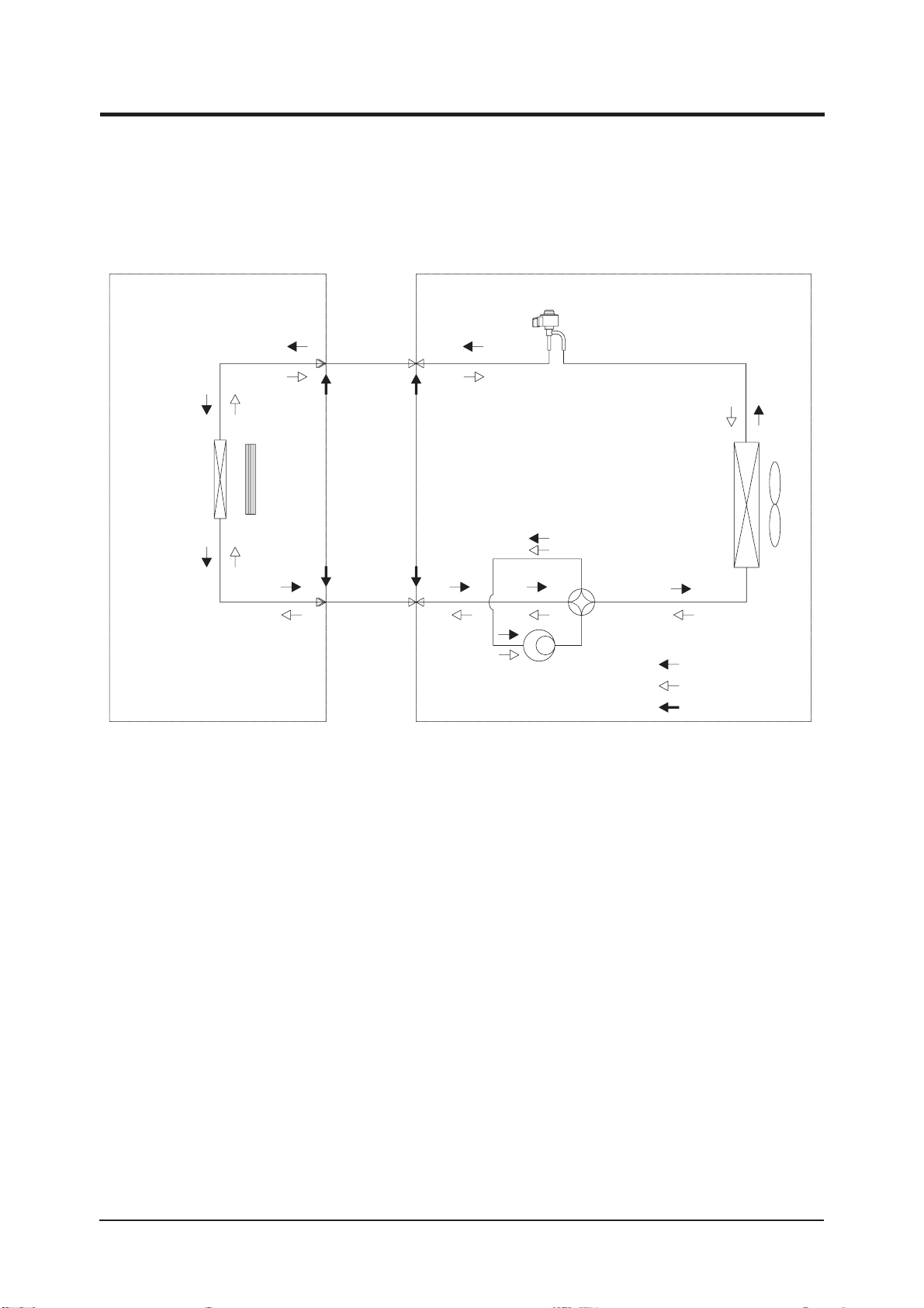
3FGSJHFSBUJOH$ZDMF%JBHSBN
*OEPPS6OJU 0VUEPPS6OJU
XBZWBMWF
)FBU
&YDIBOHFS
&WBQPSBUPS
$SPTT'BO
-JRVJETJEF
(BTTJEF
XBZWBMWF
$PNQSFTTPS
&YQBOTJPOWBMWF
)FBU
&YDIBOHFS
$POEFOTFS
1SPQFMMFS'BO
XBZWBMWF
$PPMJOH
)FBUJOH
(BT-FBL$IFDL1PJOU
4BNTVOH&MFDUSPOJDT
3. Disassembly and Reassembly
Necessary Tools
Item Remark
+SCREW DRIVER
MONKEY SPANNER
Samsung Electronics 3-1
3-1 Indoor Unit
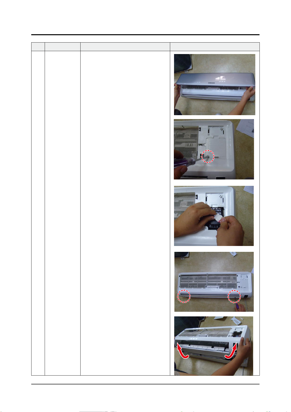
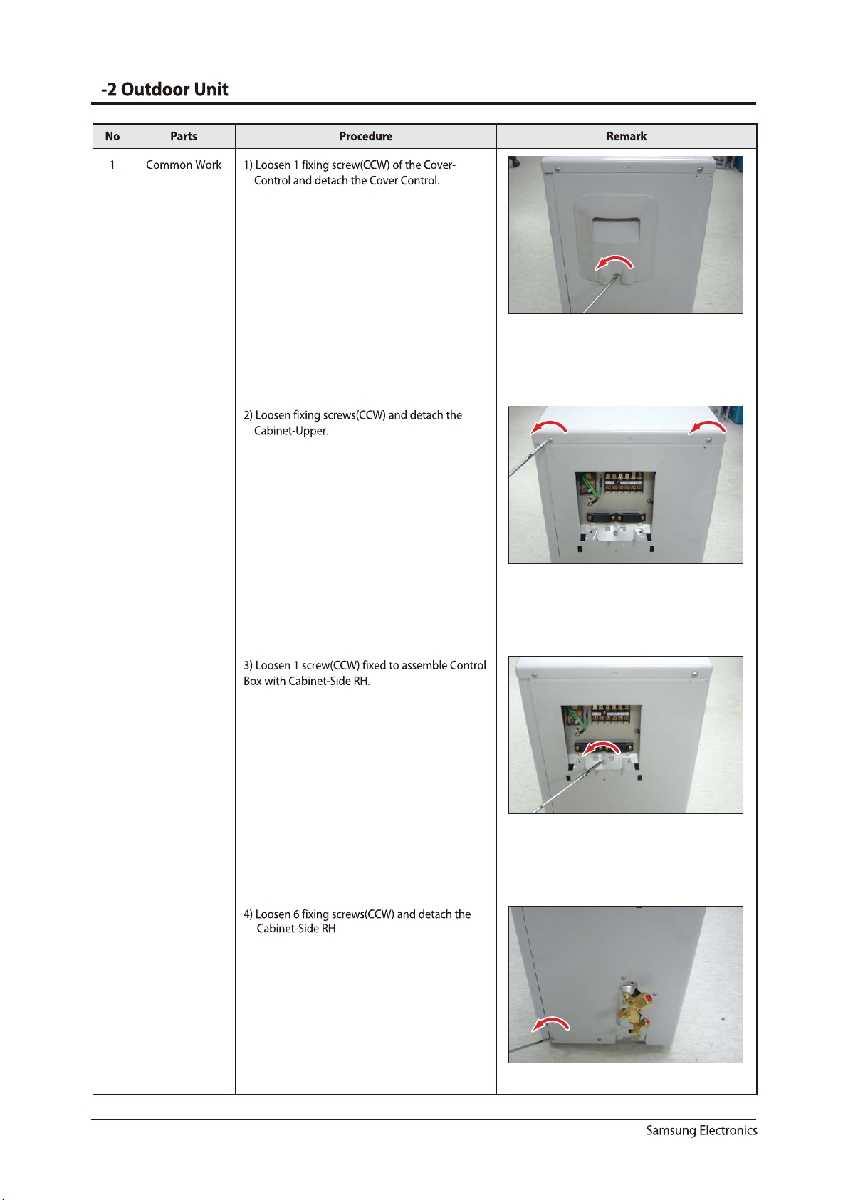
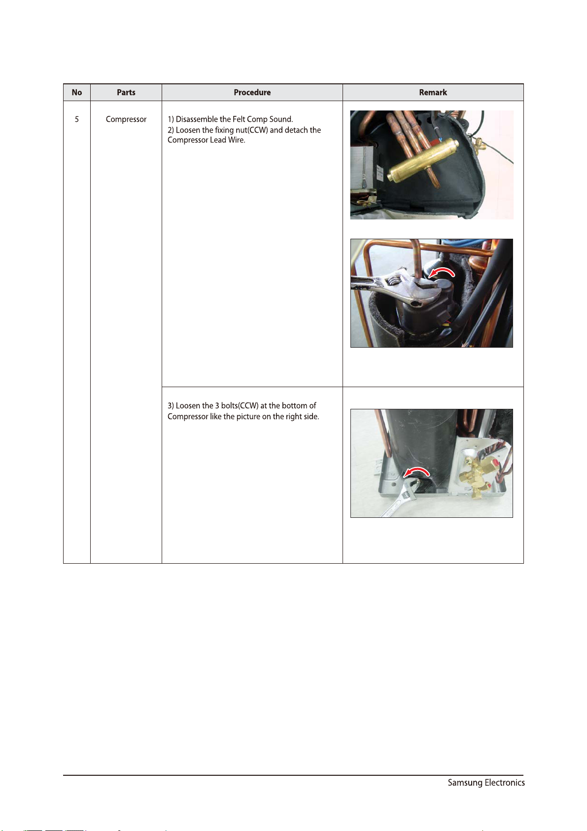
No Parts Procedure Remark
1 PANEL-FRONT 1) Stop the driving of air conditioner and shut off
main power supply.
2) Open the FRONT-GRILLE and pull out from the
PANEL-FRONT.
3) Detach COVER-TERMINAL from the PANELFRONT.(use + Screw Driver)
4) Loosen connector wire(white) and detach the
temperature sensor wire.
5) To detach the FRONT-PANEL the main frame,
unfasten 2 screw at the bottom.(use + Screw
Driver)
6) Take off the FRONT-PANEL,lifting up the bottom.
3-2 Samsung Electronics
Operating Instructions and Installation
No Parts Procedure Remark
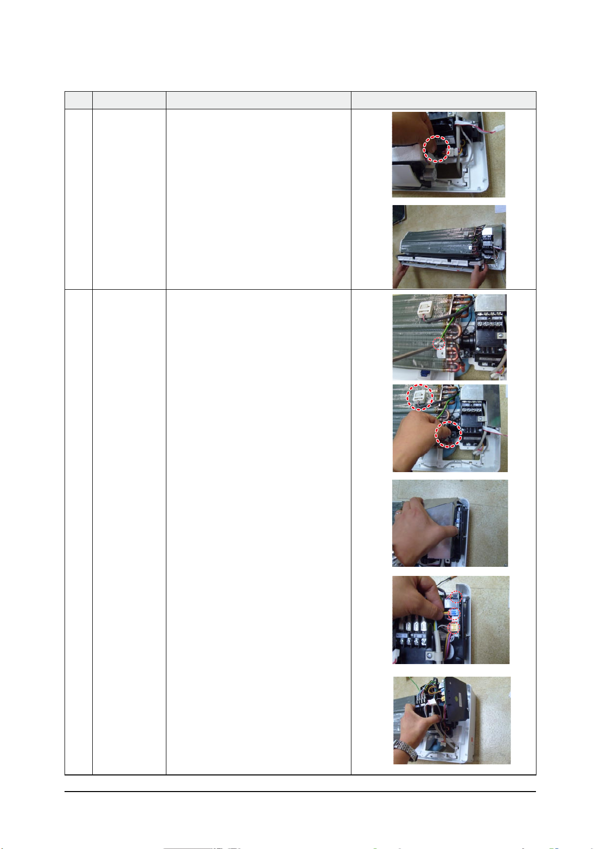
2 TRAY DRAIN 1) Loosen stepping motor wire and detach the
hook of main frame.
2) To detach TRAY-DRAIN from the main frame,
pull the bottom of the TRAY-DRAIN towards
you.
3 CONTROL IN 1) Unfasten the earth screw.(use + Screw Driver)
2) Detach the temperature sensor and Humidity
sensor.
3) Detach COVER-CONTROL from the CASECONTROL.
4) Loosen MPI connector wire(yellow), and MOTOR
wires(white,blue).
5) Take off the CASE-CONTROL from the main
frame.
Samsung Electronics 3-3
Operating Instructions and Installation
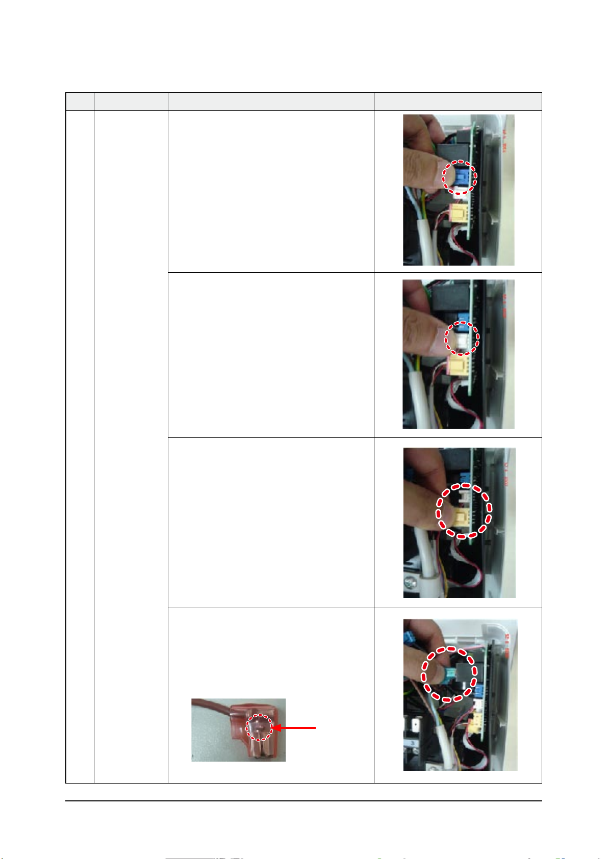
No Parts Procedure Remark
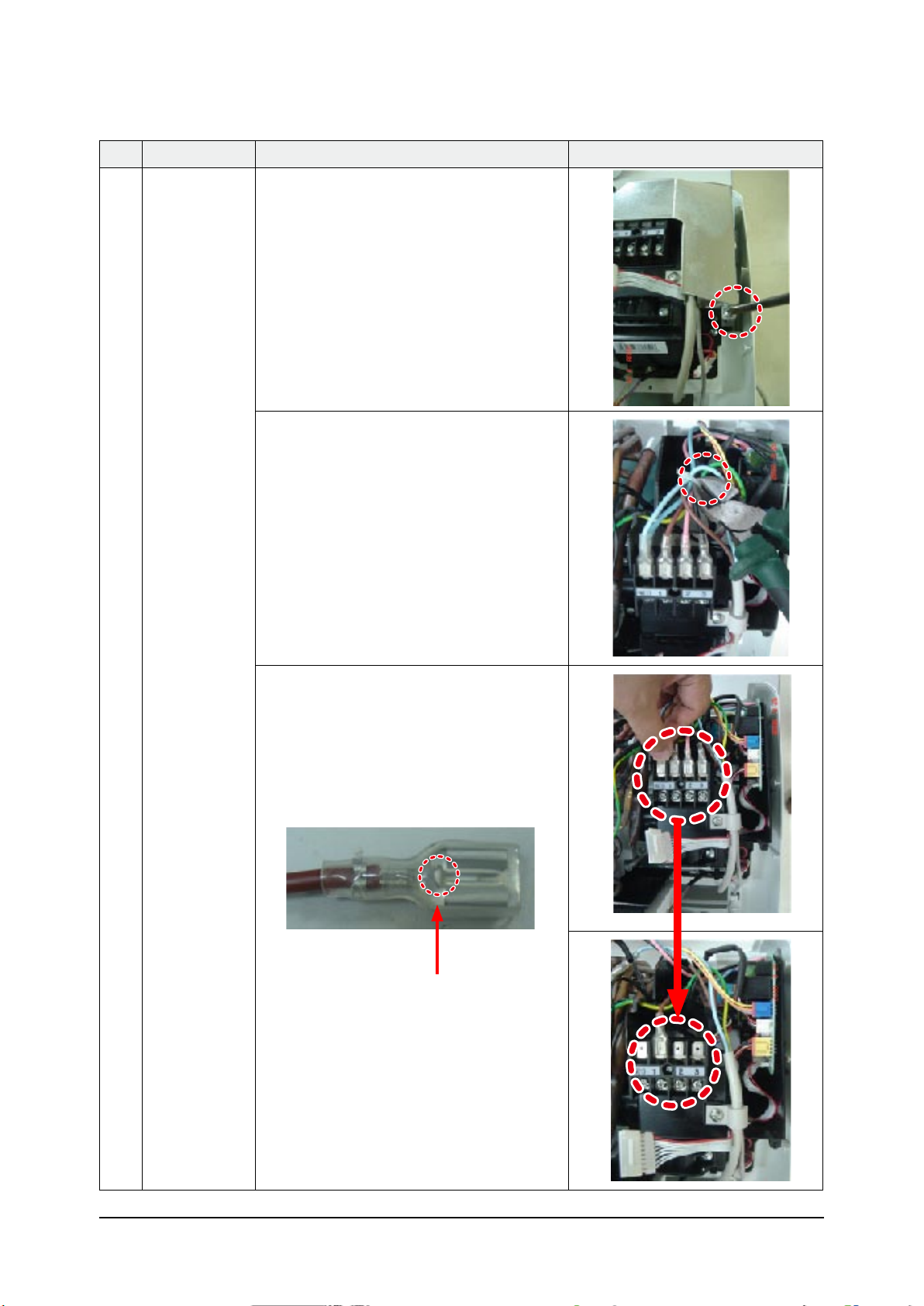
4 PBA 1) Unfasten the screw.
2) Cut the cable tie.
3) Loosen the terminal block wires.
(Total 4EA: #N(T)-2EA, #2-TEA, #3-TEA)
Caution:
The terminal is locking type.
So, when you separate terminals,
pull pressing the button.
Button
3-4 Samsung Electronics
Operating Instructions and Installation
No Parts Procedure Remark
4 PBA 4) Loosen the Motor Feedback connector(CN44).
Caution:
When you separate the connector,
pull pressing the locking button.
5) Loosen the Humidity sensor connector(CN42).
Option connector.
Caution:
When you separate the connector,
pull pressing the locking button.
6) Loosen the MPI connector(CN81).
Option connector.
Caution:
When you separate the connector,
pull pressing the locking button.
7) Loosen the Relay #4 blue-connector(RY71).
Caution:
The terminal is locking type.
So, when you separate terminals,
pull pressing the button.
Button
Samsung Electronics 3-5
Operating Instructions and Installation
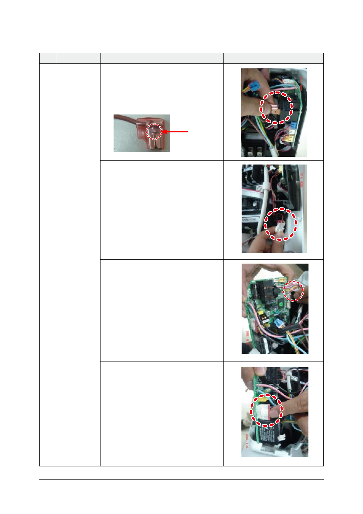
No Parts Procedure Remark
4 PBA 8) Loosen the Relay #3 red-connector(RY71).
Caution:
The terminal is locking type.
So, when you separate terminals,
pull pressing the button.
Button
9) Loosen the Step motor connector.
Caution:
When you separate the connector,
pull pressing the locking button.
10) Loosen the Thermistor wire connector(CN43).
Caution:
When you take off the PBA, don’t touch
the components.
Please hold the PBA both side.
11) Loosen the Motor connector(CN71).
Caution:
When you separate the connector,
pull pressing the locking button.
3-6 Samsung Electronics

Operating Instructions and Installation
No Parts Procedure Remark
4 PBA 12) Take off the main PBA from the ASS’Y
Control in.
Caution:
When you take off the PBA, don’t touch
the components.
Please hold the PBA both side.
Samsung Electronics 3-7
Operating Instructions and Installation
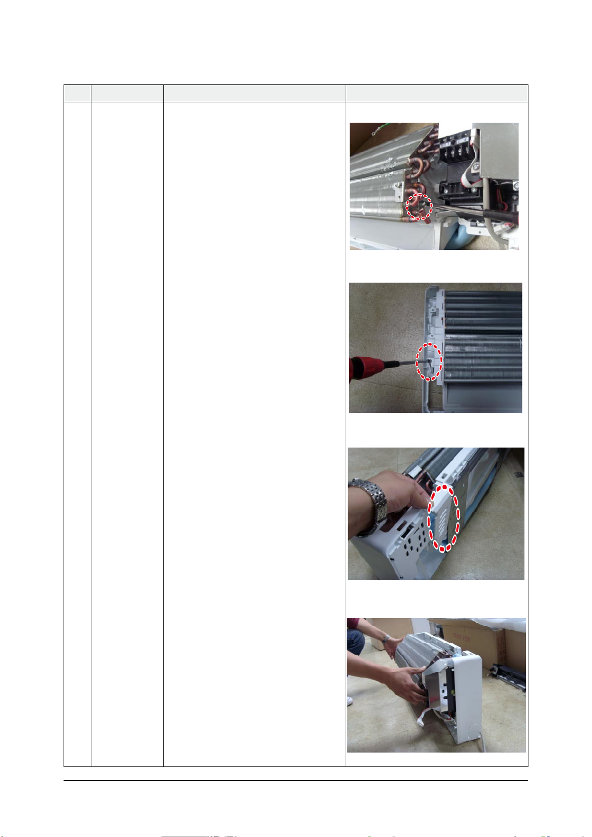
No Parts Procedure Remark
5 EVAPORATOR 1) Unfasten the screw at the right side.
(use + Screw Driver)
2) Unfasten the screw at the left side.
(use + Screw Driver)
3) Detach the HOLDER PIPE.
4) Take off the EVAPORATOR
from the main frame.
3-8 Samsung Electronics
Operating Instructions and Installation
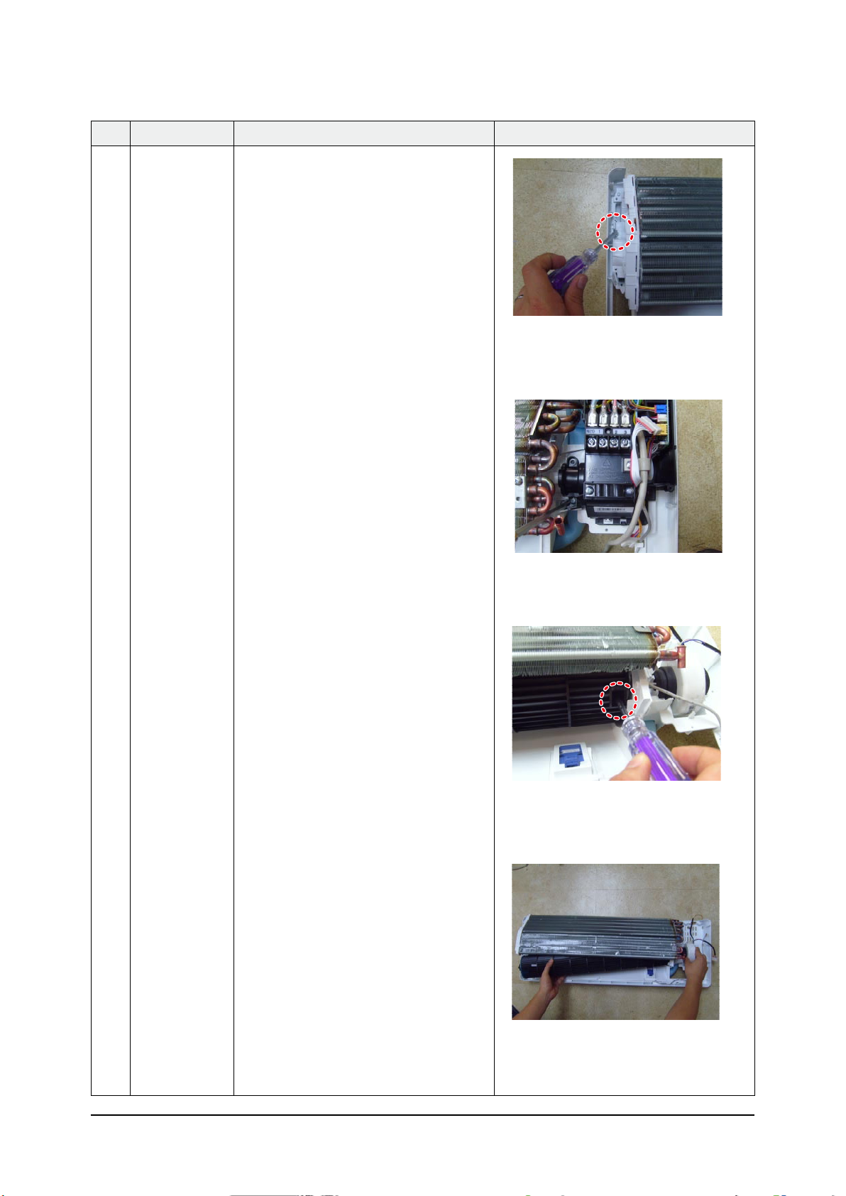
No Parts Procedure Remark
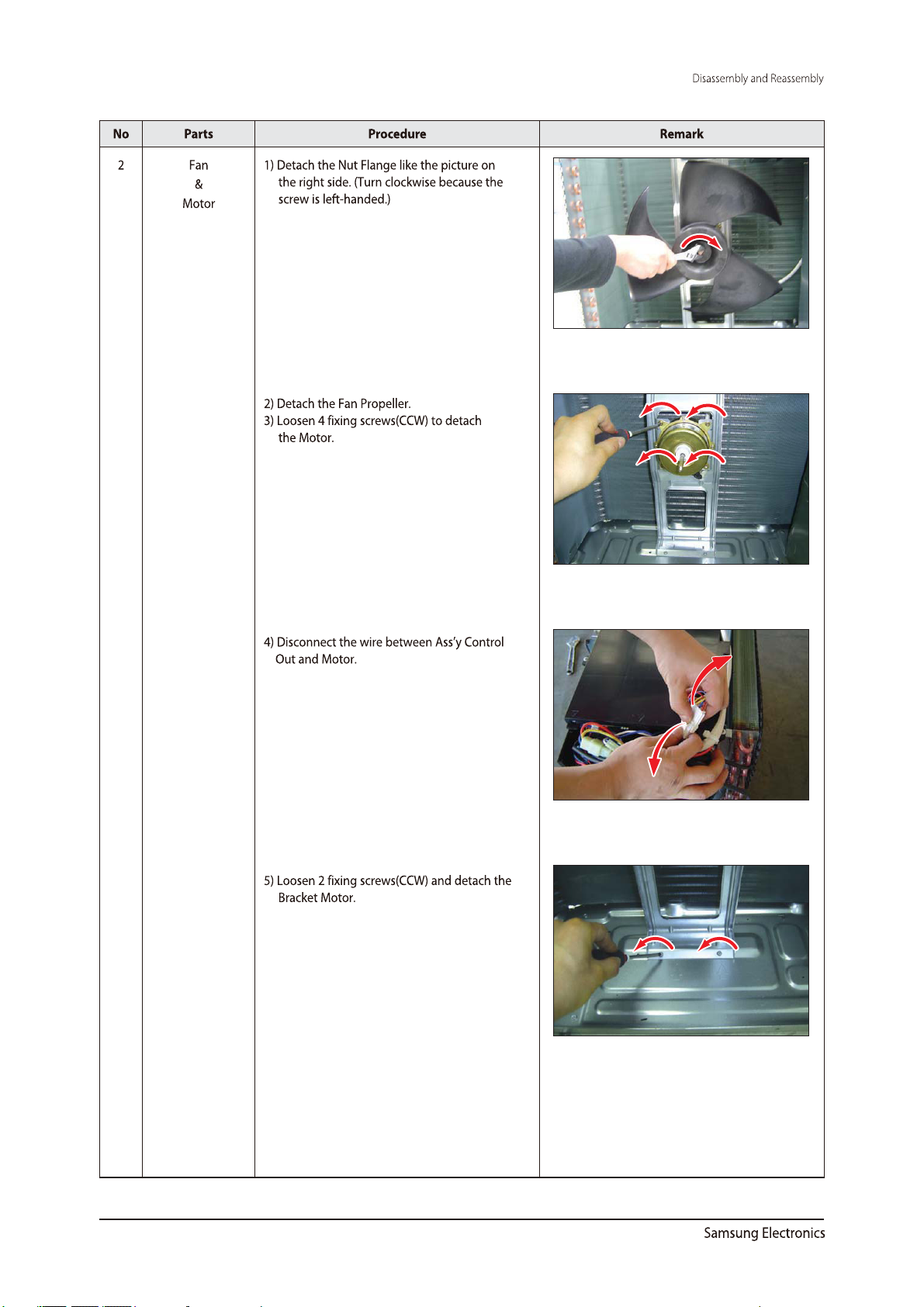
6 FAN MOTOR
&
CROSS FAN
1) Unfasten the screw in the HOLDER-EVAP on the
left side of evaporator.(use + Screw Driver)
2) unfasten the 3 points screws in the CASE-
CONTROL, and then detach the CASE.
(use + Screw Driver)
3) unfasten the screw a little.(use + Screw Driver)
4) Lift up the evaporator slightly and
pull the CROSS-FAN to the left side.
Samsung Electronics 3-9
3
3-10
3-11
3-12
3-13
3-14
6.Electrical Parts List
INDOOR MAIN PCB(DB93-07499B)
D701 0402-000012 DIODE-RECTIFIER;UF4007,1KV,1A,DO-41,TP 1
D4201 0402-000137 DIODE-RECTIFIER;1N4007,1KV,1A,DO-41,TP 1
ZD4201 0403-000252 DIODE-ZENER;BZX84C3V6,3.4-3.8V,350MW,SOT-23,TP 1
ZD4203 0403-000258 DIODE-ZENER;BZX84C5V6,5.6,225mW,SOT-23,TP 1
ZD4202 0403-001285 DIODE-ZENER;BZX84-C11,10.4-11.6V,350mW,SOT-23,TP 1
Q2321,Q401 0501-000534 TR-SMALL SIGNAL;2SC2412K,NPN,200mW,SOT-23,TP,180- 2
Q6103 0501-002296 TR-SMALL SIGNAL;MMST2907A,PNP,200MW,SMT3,TP,100-3 1
Q6101,Q6102 0504-000127 TR-DIGITAL;FJV3102RMTF,NPN,200MW,10K/10K,SOT-23,T 2
Q4201 0504-001064 TR-DIGITAL;DTC114EKA,NPN,200mW,10K/10K,SOT-23,TP 1
IC05,IC06,IC07 0506-000175 TR-ARRAY;2003,NPN,7,1W,SOP-16,ST,1000 3
PC2321 0604-001003 PHOTO-COUPLER;TR,50-150%,200mW,DIP-4,ST 1
PC4201 0604-001038 PHOTO-COUPLER;TR,130-260%,200mW,DIP-4,ST 1
IC361 1103-001175 93LC56,128x16,SOP,8P,5x4mm,2.5/6.0V,-40to+85C 1
IC4202 1203-000274 IC-POSI.FIXED REG.;7805,TO-220,3P,-,PLASTIC,4.8/5 1
IC4201 1203-002545 IC-PWM CONTROLLER;266,DIP,8P,300MIL,PLASTIC,-0.3/ 1
IC0102 1203-003334 IC-RESET;S-801,SOT-23,5P,2.9x1.6mm,PLASTIC,3.716/ 1
VA71 1405-000160 VARISTOR;680V,4500A,17.5x6.5mm,T
P,INR14D681KORSY 1
R4204,R4205 2002-001104 R-COMPOSITION;12Mohm,5%,1/2W,AA,TP,3.4x9mm 2
R4203 2003-000448 R-METAL OXIDE(S);100Kohm,5%,2W,AA,TP,4x12mm 1
R6107,R6106,R0101
,R403,R404,R405,R2
322,R2323
,PT,W01/1,%5,mhoK8.6;PIHC-R780000-70021066R,104R
R301,R302,R406,R5
01,R6105,R6602
T,W4/1,%5,mho01;PIHC-R213000-70028024R
R201,R202,R203,R2
04,R205,R206,R207,
R208
YT'QCEPS_CSEDEDOCNOITACOL
1PT,-,A2,V002,D2GU;REIFITCER-EDOID491100-20402024D
1PT,4-DMS,A1,V006,S60FD;EGDIRB-EDOID892100-20401024DB
18061,PT,W01/1,%5,mho001;PIHC-R470000-70026024R
38061,PT,W01/1,%5,mho033;PIHC-R670000-70026012R,4012R,2012R
18061,PT,W01/1,%5,mho074;PIHC-R770000-70022024R
88061,PT,W01/1,%5,mhoK1;PIHC-R870000-7002
28061,PT,W01/1,%5,mhoK2;PIHC-R080000-70024016R,3016R
18061,PT,W01/1,%5,mhoK7.4;PIHC-R480000-70021024R
28061,PT,W01/1,%5,mhoK7.4;PIHC-R480000-7002204R,1232R
28061
68061,PT,W01/1,%5,mhoK01;PIHC-R090000-7002
28061,PT,W01/1,%5,mhoK74;PIHC-R790000-7002263R,163R
08061,PT,W01/1,%5,mhoK74;PIHC-R790000-70027012R
18061,PT,W01/1,%5,mhoM1;PIHC-R901000-70022010R
38061,PT,W01/1,%5,mho021;PIHC-R611000-7002603R,503R,303R
18061,PT,W01/1,%5,mho065;PIHC-R911000-70028016R
18061,PT,W01/1,%5,mhoK2.2;PIHC-R421000-70027024R
16123,P
86123,PT,W4/1,%5,mhoK74;PIHC-R449000-7002
6-1
Samsung Electronics
INDOOR MAIN PCB(DB93-07499B )(CONT.)
YT'QCEPS_CSEDEDOCNOITACOL
R201,R202,R203,R204,R2
05,R206,R207,R208
C4202 2201-000983 C-CERAMIC,DISC;1NF,10%,2KV,7.5mm 1
C701 2201-000983 C-CERAMIC,DISC;1NF,10%,2KV,7.5mm 0
C4203,C4204 2201-000987 C-CERAMIC,DISC;2.2NF,20%,400V,Y5U,BK,12.5X6MM,10 2
C4205 2201-002193 C-CERAMIC,DISC;0.082nF, 10%,3000V,5mm 1
C361,C401,C2322,C2323
2203-000257 C-CER,CHIP;10nF,10%,50V,X7R,TP,1608 6
,C6101,C6102
C301,C302,C305,
2203-000440 C-CER,CHIP;1nF,10%,50V,X7R,TP,1608,- 5
C402,C509
C0101,C0102,C0103,C01
2203-005249 C-CER,CHIP;100nF,10%,50V,X7R,TP,1608,- 17
04,C0105,C0106,C0107,
C2102,C2103,C403,C232
1,C4201,C4206,C4207,K
C46,KC47,C6601
C2101 2203-005249 C-CER,CHIP;100nF,10%,50V,X7R,TP,1608,- 1
XC71,XC72 2301-001220 C-FILM,LEAD-PPF;100nF,10%,275V,BK,18x6x12,15 2
CR71 2301-001363 C-FILM,LEAD-PPF;2000nF,+10-5%,450V,BK,38x18x30mm,3 1
CE4205 2401-000038 C-AL;470uF,20%,25V,GP,TP,85
CE4204 2401-000151 C-AL;1000uF,20%,25V,GP,TP,85
CE6101 2401-002094 C-AL;47uF,20%,25V,GP,TP,85
10x12.5mm,5mm 1
10x20,5mm 1
5x11,2.5mm 1
CE4201,CE4202 2401-004330 C-AL;22μF,20%,500V,-,TP,12.5X25,7.5mm 2
L4201 2702-001118 INDUCTOR-RADIAL;5000uH,10%,8.0x11.0mm 1
X0101 2802-001179 RESONATOR-CERAMIC;4MHZ,0.5%,BK,8X3X5.5MM 1
F701-1 3601-000263 FUSE- CAR TRIDGE;250V ,3.15A,SL O W -
BLOW,GLASS,5.2x20mm
F702 3601-001209 FUSE-RADIAL LEAD;250V,1A,TIME-LAG,-,8.5x8mm 1
CN72 3711-000262 C O N N E C T OR-
HEADER;1WALL,3P,1R,7.92MM,STRAIGHT,SN,W
CN44 3711-000879 HEADER-BOARD TO CABLE;BOX,3P,1R,2.5mm,STRAIGHT,SN 1
CN6601 3711-000941 HEADER-BOARD TO CABLE;BOX,4P,1R,2.5mm,STRAIGHT,SN 0
PCB DB41-00752A VIVALDI INDOOR INVERTER PCB FR-4 0
PCB DB41-00794A VIVALDI INDOOR INVERTER PCB FR-4 1
CN91(1-8) DB93-06896C Vivaldi-P/J,190mm,25045TP,SMH250-5HRT,AWG#26,SSEC 1
86123,PT,W4/1,%5,mhoK74;PIHC-R449000-7002
28061,PT,W01/1,%1,mhoK8.6;PIHC-R860100-70025012R,3012R
1-,ZHK2,-,-,BD58;OZEIP-REZZUB921100-20031016ZB
1Sm1,Sm1,A2,-,cdV21;RSS511000-205317SS
1
1
1ERIW TCENNOCA49110-93BD22NC
1M001,-,V005;ESUF-REDLOHA42900-16BD107F
1ABP BUS ROODNIC75240-39BDABP BUS 584
1PAC ROTSIRAVA24900-76BD17AV
Samsung Electronics
6-2
3
Electrical Part List
OUTDOOR MAIN PCB DB93-07112K (AQV18E**),DB93-07112L(AQV24E**)
D451,D452,D453,D454 0401-000133 DIODE-SWITCHING;RLS4148,75V,150mA,LL-34,TP 4 4
D103,D104,D105,D106 0402-001427 DIODE-RECTIFIER;ES1D,200V,1A,DO-214AC,TP 4 4
D102,D401,D402,D403 0402-001429 DIODE-RECTIFIER;US1J,600V,1A,DO-214AC,TP 4 4
BD01 0402-001553 DIODE-BRIDGE;GBPC3506W,600V,35A,SQUARE-4,BK 1 1
ZD451,ZD452,ZD501,
0403-000258 DIODE-ZENER;MMBZ5232B,5%,225mW,SOT-23,TP 4 4
ZD502
CD31,CD32 0406-001109 DIODE-TVS;SAC5.0,7.6/-/-V,500W,DO-15 2 2
D201 0407-000123 DIODE-ARRAY;DAN202K,80V,100mA,CA2-3,SOT-23,TP 1 1
Q904,Q905,Q906,Q907 0504-000001 TR-DIGITAL;DTA114EKA,PNP,200mW,10K/10K,SOT-23,TP 4 4
Q801 0504-000127 TR-DIGITAL;FJV3102RMTF,NPN,200MW,10K/10K,SOT-23,T 1 1
Q902 0504-000127 TR-DIGITAL;FJV3102RMTF,NPN,200MW,10K/10K,SOT-23,T 1 0
IC51,IC52,IC53,IC54,IC55
0506-000175 TR-ARRAY;2003,NPN,7,1W,SOP-16,ST,1000 6 6
,IC72
IC12,IC61,IC62 0604-001172 PHOTO-COUPLER;TR,100-300,200mW,SOP,TP 3 3
IC30 0801-000393 IC-CMOS LOGIC;74HC86,OR GATE,SOP,14P,150MIL,QUAD,S 1 1
IC21 1202-000104 IC-VOLTAGE COMP.;393,SOP,8P,150MIL,DUAL,36V,CMO 1 1
IC16,IC19 1203-000274
IC-POSI.FIXED REG.;7805,TO-220,3P,-,PLASTIC,4.8/5 2 2
IC13 1203-002948 IC-POSI.ADJUST REG.;TL431ACD,SOP,8P,4.9X3.9MM,PLA 1 1
IC59 1203-003334 IC-RESET;S-801,SOT-23,5P,2.9x1.6mm,PLASTIC,3.716/ 1 1
IC11 1203-003527 IC-PWM CONTROLLER;TOP243,DIP,7P,9.83x6.6mm,PLASTIC 1 1
R107 2003-000708 R-METAL OXIDE(S);47ohm,5%,1W,AA,TP,3.3x9mm 1 1
R101 2003-000855 R-METAL OXIDE(S);47Kohm,5%,3W,AA,TP,6x16mm 1 1
R110 2003-002246 R-METAL OXIDE(S);620ohm,5%,1W,AA,TP,2.4x6.4mm 1 1
R001 2006-001168 R-CEMENT;200ohm,5%,10W,CB,BK,15.7x11.5x34.2mm 1 1
R401,R402,R403,R404,R
405,R406
R504,R505,R506,R507,R
553,R606,R607
R103,R512,R557,R559,R
601,R604
2802R,502R
R324,R325,R327,R328,
R407
R302,R303,R304,R305,
R306,R316,R509,R552,
R554,R555,R556,R558,
R560,R561,R562,R563,
R566,R573,R574,R805,
R916,R917
0-7002155R
K42 K81 CEPS_CSEDEDOCnoitacol ngiseD
11P3-OT,W591,-,A08,V006,- ;TBGI-RT451100-8050308Q
11REVIECSNART SUB-CI173100-600102CI
11TNEMEC R-YSSA541100-6002124R
668061,PT,W01/1,%5,mho001;PIHC-R470000-7002
778061,PT,W01/1,%5,mho033;PIHC-R670000-7002
338061,PT,W01/1,%5,mho074;PIHC-R770000-7002808R,243R,323R
668061,PT,W01/1,%5,mhoK1;PIHC-R870000-7002
228061,PT,W01/1,%5,mhoK2;PIHC-R080000-700
118061,PT,W01/1,%5,mhoK3.3;PIHC-R280000-7002401R
558061,PT,W01/1,%5,mhoK7.4;PIHC-R480000-7002
11 8061,PT,W01/1,%5,mhoK74;PIHC-R790000-7002513R
018061,PT,W01/1,%5,mhoK8.6;PIHC-R780000-7002419R
22228061,PT,W01/1,%5,mhoK01;PIHC-R090000-7002
018061,PT,W01/1,%5,mhoK01;PIHC-R090000-7002319R
118061,PT,W01/1,%5,mhoM1;PIHC-R901000-7002015R
118061,PT,W01/1,%5,mhoM1;PIHC-R90100
118061,PT,W01/1,%5,mho8.6;PIHC-R111000-7002201R
338061,PT,W01/1,%5,mho33;PIHC-R311000-7002014R,904R,804R
Samsung Electronics
6-4
Electrical Part List
OUTDOOR MAIN PCB DB93-07112K (AQV18E**),DB93-07112L(AQV24E**),(CONT.)
,PT,W01/1,%1,mho074;PIHC-R929000-7002214R
R900,R901,R902,R903,R
904,R905,R906
R106,R203,R204 2007-007342 R-CHIP;1.82Kohm,1%,1/10W,TP,1608 3 3
R105 2007-007445 R-CHIP;9.09Kohm,1%,1/10W,TP,1608 1 1
,711R,611R
C307,C308,C309,C310 2201-000154 C-CERAMIC,DISC;10NF,+80-20%,2KV,Y5P,TP,20X5MM,7.5 4 4
C105,C106 2201-000322 C-CERAMIC,DISC;2.2NF,10%,2KV,Y5P,TP,13X5MM,10 2 2
C903 2201-000322 C-CERAMIC,DISC;2.2NF,10%,2KV,Y5P,TP,13X5MM,10 1 0
C411,C412,C413,C414,
2203-000125 C-CER,CHIP;1.2nF,10%,50V,X7R,TP,1608,- 6 6
C415,C416
C201,C203,C204,C205,
2203-000257 C-CER,CHIP;10nF,10%,50V,X7R,TP,1608,- 18 18
C301,C451,C452,C453,
C454,C567,C603,C607,
C801,C900,C901,C902,
C907,C908
C108 2203-001414 C-CER,CHIP;330NF,10%,50V,X7R,TP,2012 1 1
C318,C319,C320,C321 2203-002002 C-CER,CHIP;33pF,5%,50V,NPO,BK,1608,- 4 4
C109,C112,C116,C117,
2203-005249 C-CER,CHIP;100nF,10%,50V,X7R,TP,1608,- 47 47
C121,C202,C302,C303,
C304,C305,C306,C404,
C405,C406,C407,C408,
C409,C410,C417,C418,
C501,C502,C503,C504,
C505,C506,C507,C508,
C509,C510,C511,C512,
C513,C553,C554,C555,
C556,C560,C561,C563,
C565,C568,C570,C575,
C576,C706,C3011
C113,C122,C802 2203-005261 C-CER,CHIP;1000nF,10%,25V,X7R,-,3216 3 3
C904 2203-006104 C-CER,CHIP;1000nF,10%,50V,X7R,3225 1 0
C008 2301-000141 C-FILM,LEAD-PEF;10nF,10%,630V,TP,16x11x7.5mm,5 1 1
C422,C803 2306-000123 C-FILM,LEAD-PPF;100nF,5%,630V,BK,26x16.5x8.5,2/
2 2
100nF,5%,630V,17x12x6,15mm
C552,C559,C562,C564,
2401-000493 C-AL;10uF,20%,50V,LZ,TP,5x11mm,5mm ,105
7 7
C569,C574,C577
C906 2401-000493 C-AL;10uF,20%,50V,LZ,TP,5x11mm,5mm ,105
1 0
K42K81 CEPS_CSEDEDOCnoitacol ngiseD
118061,PT,W01/1,%5,mho021;PIHC-R611000-7002103R
116123,PT,W4/1,%1,mhoK3.41;PIHC-R583000-7002511R
228061,PT,W01/1,%1,mhoK81;PIHC-R554000-7002515R,205R
338061,PT,W01/1,%5,mhoK4.2;PIHC-R215000-7002807R,707R,607R
116123,PT,W4/1,%5,mho02;PIHC-R355000-7002708R
228061,PT,W01/1,%1,mhoK42;PIHC-R416000-7002415R,305R
336123,PT,W4/1,%1,mhoK074;PIHC-R429000-7002411R,311R,211R
118061
116123,PT,W4/1,%5,mho74;PIHC-R059000-7002608R
448061,PT,W01/1,%5,mhoK1.5;PIHC-R569000-7002219R,119R,019R,115R
338061,PT,W01/1,%5,mhoK2.8;PIHC-R971100-7002909R,809R,709R
776123,PT,W4/1,%5,mhoK1;PIHC-R813100-7002
446123,PT,W4/1,%1,mhoK9.09;PIHC-R766200-7002702R,602R,202R,102R
335205,PT,W2/1,%1,mhoK051;PIHC-R162800-7002811R
228061,R7X,V05,%01,Fn22;PIHC,REC-C893200-3022024C,914C
115,11x3.6,PT,PG,V52,%02,Fu001;LA-C303000-1042321C
6
-5
Samsung Electronics

Electrical Part List
OUTDOOR MAIN PCB DB93-07112K (AQV18E**),DB93-07112L(AQV24E**)(CONT.)
C905 2401-000880 C-AL;220uF,20%,50V,WT,TP,10x16mm,5m 1 0
C114,C421 2401-002274 C-AL;220uF,20%,35V,WT,TP,8x11.5mm,5 ,105
C107,C118,C401,
2401-002438 C-AL;47μF,20%,50V,WT,TP,6.3x11,5mm,105
2 2
5 5
C402,C403
C104 2401-003541 C-AL;10uF,20% ,450V,WT,TP,12.5x20mm,5 1 1
C119,C805 2401-003585 C-AL;220uF,20%,35V,WT,TP,8x11.5mm,5 ,105
2 2
C110 2401-001374 C-AL;470uF,20%,16V,WT,TP,10x12.5mm,5mm 1 1
C101,C102,C103 2401-003740 C-AL;560uF,20%,400V,WT,BK,35x50mm,10 ,105
3 3
XTAL51 2802-001179 RESONATOR-CERAMIC;4MHZ,0.5%,BK,8X3X5.5MM 1 1
XTAL 2802-001198 RESONATOR-CERAMIC;10MHZ,0.5%,BK,8X3X5.5MM 1 1
RY03,RY04 3501-001154 RELA Y -
0 2
MINIATURE;12Vdc,200mW,3000mA,1FormA,10mS,10m
RY05 3501-001154 RELA Y -
1 1
MINIATURE;12Vdc,200mW,3000mA,1FormA,10mS,10m
RY31 3501-001248 RELAY-MINIATURE;12V,-,11.7MA,DPDT,4MS,4MS 1 1
RY01 3501-001268 RELAY-POWER;12V,0.9W,25000mA,SPST,20mS,10mS 1 1
11ELBAC OT DRAOB-REDAEH348300-117300NC
01REDAEH-ROTCENNOC910400-117317NC
CN34 3711-004182 CONNECTOR-HEADER;BOX,10P,1R,2MM,STRAIGHT,SN,NTR 1 1
CN61 3711-004484 CONNECTOR-HEADER;BOX,5P,1R,2mm,STRAIGHT,SN 1 1
REACTOR01,
3712-001139 CONNECTOR-TERMINAL;TAB,MALE,-,6.35X0.8MM 2 2
REACTOR02
Q901 DB13-00003A IC DRIVER GATE;-,SOT-23,-,-,1P,1P,0.2mm,2.93x1.3mm 1 0
PT02 DB26-00075A TRANS PULSE;PT_50,MH080FXEA4,10,65.5,8~14,EI2218, 1 1
IC451,IC452 DB32-00173A SENSOR M A G - C T S ENSO R;ASC712,5H P
2 2
INVERTER,-,-40~150
11BCPA87700-14BDNIAM BCP
IC01 DB91-00532E XSA OUTDOOR Inv Micom,MN103SFA7K,80P, ROM Size:
0 1
256K bytes
IC01 DB09-00517A IC MICOM;MN103FA7K,-,80P,+5V,10 MHz,Flash Memory, 0 1
IC01 DB91-00744A OUTDOOR Inv
Micom,MN103SFA7K,80P, ROM Size: 256K
1 0
bytes
IC01 DB09-00517A IC MICOM;MN103FA7K,-,80P,+5V,10 MHz,Flash Memory, 1 0
IC50 DB91-00945A ASSY MICOM 09R FORTE,VIVACE, MONTBLANC 18K24K 1 1
IC50 DB09-00338A IC MICOM;MB90F823,-,80 P,5 V,24 MHz,STM-0493-OA,- 1 1
01ATAD MORPEEA54800-19BD107CI
IC701 1103-001038 IC-EEPROM;93LC66,4KBIT,256X16BIT,SOP,8P,5X4MM,-,2 1 0
10ATAD MORPEEA44800-19BD107CI
IC701 1103-001038 IC-EEPROM;93LC66,4KBIT,256X16BIT,SOP,8P,5X4MM,-,2 0 1
11ERIW TCENNOCB33340-39BD584 MMOC W/L
11ERIW TCENNOCB53340-39BDPMOC W/C
10ERIW TCENNOCA83340-39BDDER, ULB,LEY
11ERIW TCENNOCA44340-39BDHTRAE W/L
11ERIW TCENNOCA94340-39BDYAW 4 W/C
11ERIW TCENNOCA15340-39BD1_L REWOP W/L
W TCENNOCB15340-39BDN REWOP W/L
11ERI
IC81 DB95-00595A ASSY-PHOTO COUPLER;MH080FXEA4,- 1 1
10 IHSIBUSTIM MPI-YSSAA45900-59BDMPI
01 IHSIBUSTIM MPI-YSSAA06900-59BDMPI
11PJ03PEF;REIFITCER EDOID-YSSAA19561-89BD101D
LED2 DB98-16600A ASSY-LED GREEN;---------------------------------- 1 1
K42 IK81 CEPS_CSEDEDOCnoitacol ngiseD
Samsung Electronics
6-6

Electrical Part List
OUTDOOR MAIN PCB DB93-07112K (AQV18E**),DB93-07112L(AQV24E**),(CONT.)
LED1 DB98-16601A ASSY-LED RED;---------------------------------- 1 1
LED3 DB98-16602A ASSY-LED YEL;---------------------------------- 1 1
CN51 DB98-22298A ASSY-HOOK WHT;INVERTER,SMAW250A-04,RED 1 1
CN50 DB98-22299A ASSY-HOOK WHT;INVERTER,SMAW250A-04,WHT 1 1
CN30 DB98-24921A ASSY-CONNECTOR;AS-WB670X,SMAW250A-06,WHT 1 1
K42 IK81 CEPS_CSEDEDOCnoitacol ngiseD
6-7
Samsung Electronics
 Loading...