

Samsung AM***FXVAF Series, AM***FXVAJ Series, AM***HXVAF Series, AM***KXVGJ Series, AM***KXVTJ Series Installation Manual
...
DVM S
AM✴✴✴FXVAF✴ Series
AM✴✴✴FXVAJ✴ Series
AM✴✴✴HXVAF✴ Series
AM✴✴✴HXVAJ✴ Series
AM✴✴✴KXVTF✴ Series
AM✴✴✴KXVTJ✴ Series
AM✴✴✴KXVGJ✴ Series
Air Conditioner
installation manual
imagine the possibilities
Thank you for purchasing this Samsung product.
k}tGzG㨰䛙G㐘㞬ὤGptluki]_TWZ_XYhTW_UGGGX YWX_TW]TXXGGG㝘䟸G[a[_aYY

2
Contents
Safety precautions ....................................................................................................... 3
Preparing for installation ................................................................................................. 6
Selecting installation location ........................................................................................... 11
Space requirement for installation ...................................................................................... 13
Accessories ............................................................................................................. 15
Base construction and installation of the outdoor unit ................................................................... 17
Installing the wind/snow prevention duct ............................................................................... 22
Refrigerant pipe installation ............................................................................................. 24
Electrical wiring work ................................................................................................... 59
Air tightness test and vacuum drying ................................................................................... 75
Pipe insulation .......................................................................................................... 77
Charging additional refrigerant ......................................................................................... 81
Basic segment display .................................................................................................. 83
Setting outdoor unit option switch and key function .................................................................... 83
Setting the MCU and Pipe Addresses (for HR Only) ...................................................................... 93
Things to check after completing the installation ........................................................................ 97
Inspection and trial operation ........................................................................................... 99
Automatic refrigerant amount detection function ...................................................................... 105
k}tGzG㨰䛙G㐘㞬ὤGptluki]_TWZ_XYhTW_UGGGY YWX_TW]TXXGGG㝘䟸G[a[_aYZ
3
ENGLISH
Safety precautions
WARNING
State of California Proposition 65 Warning (US only)
This product contains chemicals known to the State of California to cause cancer and birth defects or other reproductive
harm.
Please follow the following safety information for safety of the installer and the user.
❋ DVM S air conditioner uses R-410A refrigerant.
• When using R-410A, moisture or foreign substances may aect the performance and reliability of the product.
Safety precautions must be obeyed when installing the refrigerant pipe.
• The designed maximum pressure of the system is 4.1MPa(594.6 psi) and therefore select appropriate material and
thickness according to the regulations.
• R-410A is a quasi-azeotrope of two refrigerants and it has to be charged in liquid phase when lling the refrigerant.
(If you charge vapor refrigerant, it may change the blend of the refrigerant and cause product malfunction.)
❋ You must connect the indoor units for R-410A refrigerant. Refer to product catalog to nd out the models names
for connectable indoor units. (If you connect the indoor units that are not designed for R-410A, it cannot operated
normally.)
❋ After completing the installation and trial operation, explain to the user how to use and maintain the product. Also, hand
over this installation manual so that it can be stored by the user.
❋ Manufacturer is not responsible for the incidents occurred by improper installation. Installer is responsible for any
installation related claims from the user occurred by neglecting warnings and cautions stated in this manual. (Installer
will be responsible for any service charges that may occur)
❋ Generally, system air conditioners should not be relocated after installation. But when it has to be relocated for inevitable
reasons, please contact Samsung’s qualied dealers for system air conditioners.
WARNING
• Hazards or unsafe practices that may result in severe personal injury or death.
CAUTION
• Hazards or unsafe practices that may result in minor personal injury (to installer/user) or
property damage.
SEVERE WARNING SIGNS
Consult qualied installer or dealer for installation.
f When installation is done by unqualied person, problems such as water leakage, electric shock or re may occur.
Installation work must be done properly according to this installation manual.
f When installation is not done properly, it may cause water leakage, electric shock or re.
When installing the unit in a small room, take measure to keep the refrigerant concentration from exceeding allowable
safety limits in case of refrigerant leakage. Consult the dealer for precautionary measure before the installation.
f When refrigerant leaks and exceed dangerous concentration level, it may cause suocation accidents.
If any gas or impurities, except R-410A refrigerant, come into the refrigerant pipe, serious problem may occur and it
may cause injury.
Use the supplied accessories, specied components and tools for the installation.
f Do not use the pipe and the installation product used for the R-22 refrigerant.
f Failure to use the specied components can cause product fall down, water leakage, electrical shock, and re. (The pipe
and are components used for R-22 refrigerant must not be used)
Install the outdoor unit on a hard and even place that can support its weight.
f If the place cannot support its weight, the outdoor unit may fall down and it may cause injury.
k}tGzG㨰䛙G㐘㞬ὤGptluki]_TWZ_XYhTW_UGGGZ YWX_TW]TXXGGG㝘䟸G[a[_aYZ

4
Safety precautions
Check the following before installation and service work.
f Before welding, remove dangerous and inammable things that may cause an explosion and re around the work.
f Before welding, remove the refrigerant from inside the pipe or the product.
- If you perform welding while refrigerant is in the pipe, it may increase the pressure of the refrigerant and cause the pipe
to burst. If the pipe bursts or explodes, it may cause severe injury to the installer.
f When welding, use the nitrogen gas to eliminate oxidation inside the pipe.
Do not modify the product on your own.
f Potential risk of electric shock, re, product failure or injury.
Fix the outdoor unit securely on foundation to resist strong wind or earthquake.
f If the outdoor unit is not properly xed, it turns over and accidents may occur.
Electric work must be done by qualied persons, complying the national wiring regulations and installed according to
the instruction stated in the installation manual with leased circuit.
f Capacity shortage on the leased circuit and improper installation may cause electric shock or re.
Make sure to perform grounding work.
f Do not connect the ground wire to a gas pipe, water pipe, lightning rod or telephone grounding. Improper grounding
could cause electric shock.
Wiring must be connected with the designated wires and it must be xed securely so that it does not apply any external
force to the connection part of the terminals.
f If connection for xation is not properly done, it may cause heat generation or re.
Neatly arrange the wires in the electrical parts to make sure that electrical cover is closed securely without any gaps.
f If the cover is not properly closed, heat may generate on the electrical terminal and cause electric shock or re.
Exclusive circuit breaker (MCCB, ELB) must be installed to the power supply.
f When overcurrent or current leakage occurs with no circuit breaker installed, power will not be cut-o and it may cause
electric shock or re.
f Do not use damaged parts. It may cause re or electric shock.
You must cut-o the power before you work on, or adjust any power supply part for product installation, maintenance,
repair or any other services.
f There is risk of electric shock.
f Even when the power is o, it is dangerous when you come in contact with inverter PCB, fan PCB since high pressure DC
voltage is charged to those parts.
f When replacing/repairing the PCB, cut-o the power and wait until the DC voltage is discharged before replacing/
repairing them. (Wait for more than 15 minutes to allow it to discharge naturally.)
If the refrigerant gas leaks during the installation, you should ventilate the room.
f When the refrigerant gas gets in contact with ammable substance, it may generate toxic gas.
Gas leakage must be checked after installation is completed.
f When the refrigerant gas gets in contact with ammable substance, it may generate toxic gas.
You can get a frostbite if you get in contact with the leaked refrigerant gas.
Supply power to the product during winter time since the product will operate in protection mode itself when the
temperature decrease below 0°C(32°F).
f If you cut-o the power, compressor protection mode cannot be operated and may cause damage to the product.
k}tGzG㨰䛙G㐘㞬ὤGptluki]_TWZ_XYhTW_UGGG[ YWX_TW]TXXGGG㝘䟸G[a[_aYZ
5
ENGLISH
CAUTION SIGNS
Do not install the drain pipe directly to the bottom part of the outdoor unit and built a proper drainage so that water
drains out smoothly. If not, pipe may freeze or bursts during winter time and cause damage to the product or water
leakage.
f When the draining work is not done properly, water leak may occur and cause property damage.
Install the power cable and communication cable of the indoor and outdoor unit at least 1.5m(4.92ft) away from the
electric appliances and install it at least 2m(6.56ft) away from the lightning conductor.
f Noise may be generated from the electronic devices, depending on the status of the electric wave.
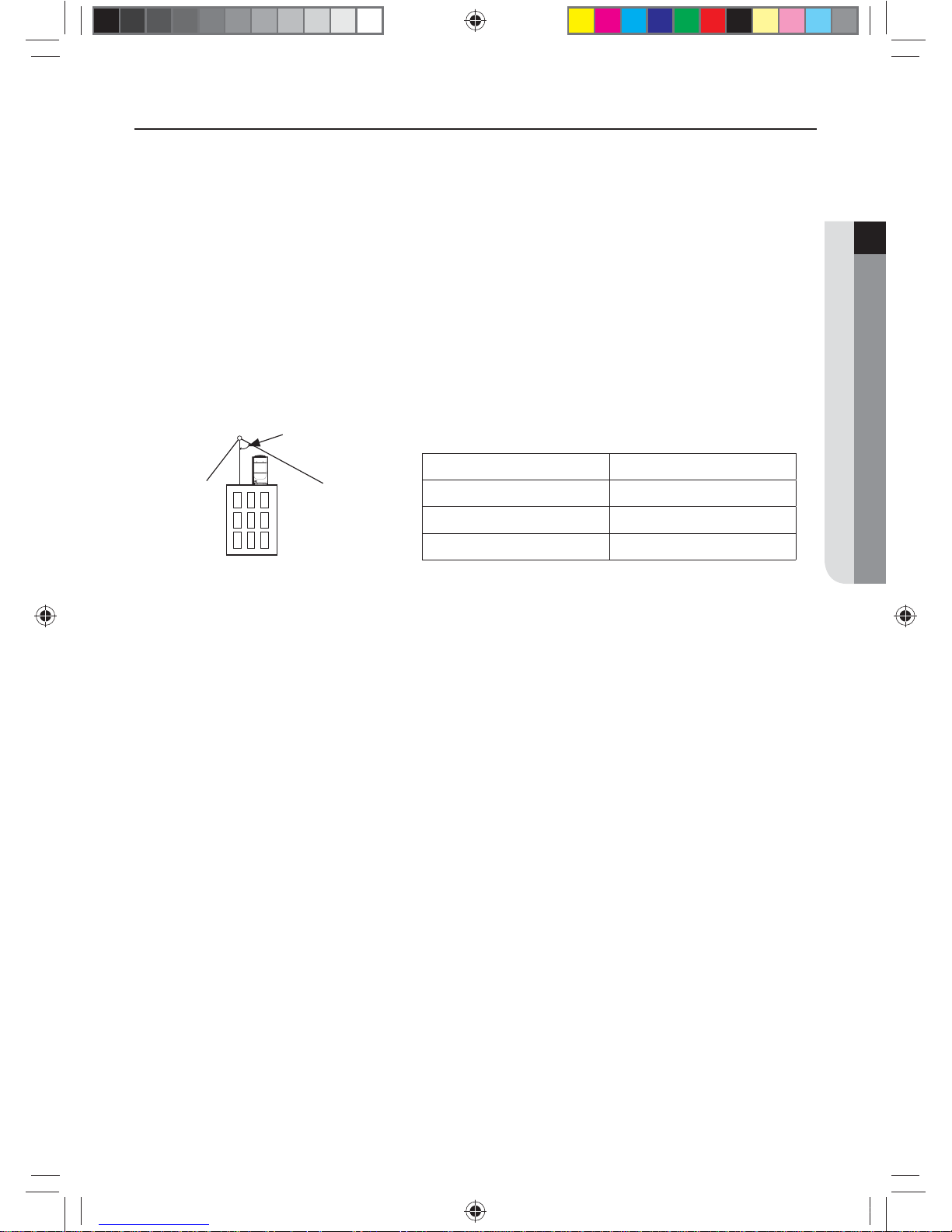
Install the outdoor unit within the angle stated in the table, according to the height of the building.
f Do not leave the refrigerant container under the hot sunlight. (There is risk of explosion.)
f You must use the appropriate pipes according to the standard since the pressure of the refrigerant is very high.
f Make sure that the pipes does not get any weaker by welding it too much.
f Make sure to install the product away from children’s’ reach. (Sharp parts of the heat exchanger is may cause personal
injury and when parts of the product gets damage, it may decrease product’s performance.)
Lighting rod
Protective angle: 25˚~55˚
Height of the building Protection control
20m(65.6 ft) or less 55˚
40m(131.2 ft) or less 35˚
60m(196.9 ft) or less 25˚
Install the indoor unit away from lighting apparatus that uses ballast stabilizer.
f If you use the wireless remote control, it may not operate normally due to ballast stabilizer.
Do not install the product in following places.
f Place where outdoor unit’s noise and warm air may disturb neighbors. (It may cause property loss.)
f Do not leave any obstacles around the inlet and outlet of the product. (It may cause damage or accidents.)
f The place where there is mineral oil or arsenic acid.
- Those parts may get damaged due to burned resin and cause water leakage or product may fall.
- The eciency of the heat exchanger may reduce or product may break.
f The place where corrosive gas such as sulfurous acid gas generates from the vent pipe or air outlet.
- The copper pipe or connection pipe may corrode and refrigerant may leak.
f The place where there is a machine that generates electromagnetic waves.
- The air conditioner may not operate normally due to problems in control system.
f The place where there is a danger of combustible gas leakage or place where thinner or gasoline is handled.
(There is risk of re or explosion.)
f The place with carbon ber or ammable dust.
f The place near seashore or hot spring where there is risk of outdoor unit corrosion.
f Do not install the product in a place where thermohygrostat is needed (such as server room, machinery room, computer
room, etc.) Those places do not provide guaranteed operation condition of the product therefore performance can be
poor in these places.
f Do not install the product in a ship or a vehicle(such as a campervan).
Salt, vibration or other environmental factor may cause the product malfunction, electric shock or re.
k}tGzG㨰䛙G㐘㞬ὤGptluki]_TWZ_XYhTW_UGGG\ YWX_TW]TXXGGG㝘䟸G[a[_aYZ
6
Safety precautions
Changes in DVM S (inverter) compare to conventional models that has to noted when installing
f For optimal distribution of the refrigerant, you must use Y-joint as branch joint for connecting outdoor units. (Do not use
T-joint)
f You cannot operate normally if you do not complete the trial operation through outdoor unit key mode. You must use
KEY MODE to run trial operation.
f DVM S air conditioner uses R-410A refrigerant.
f Check the compatibility of other products such as indoor unit, EEV kits etc. which will be connected to DVM S.
f Make sure to note that outdoor unit combination is dierent from DVM PLUS III and IV.
f The length of maximum piping, level dierence, the quantity of connectable indoor units, the installation at the outdoor
joints and the outdoor unit combinations are dierent from the conventional models.
f If the pipe length is over 2m(6.56ft) between outdoor units, make traps to prevent oil stagnation. Oil stagnation may
occur when outdoor unit at the end of module stops while other outdoor units are still in operation.
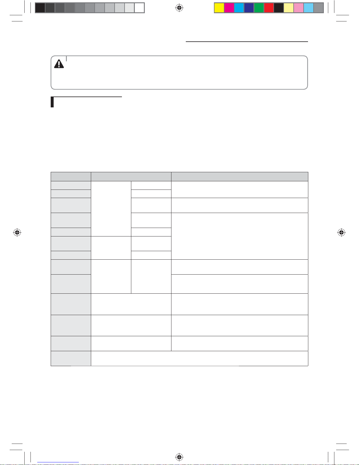
Preparing for installation
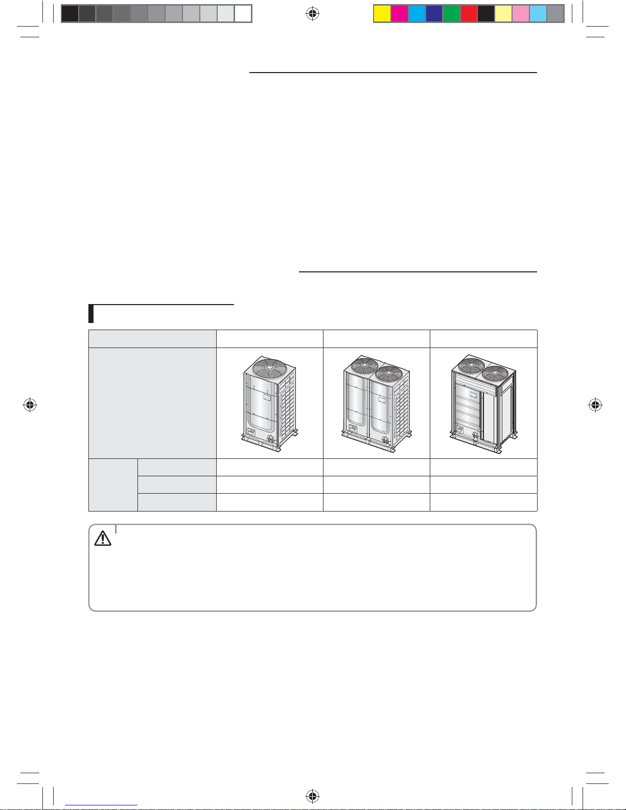
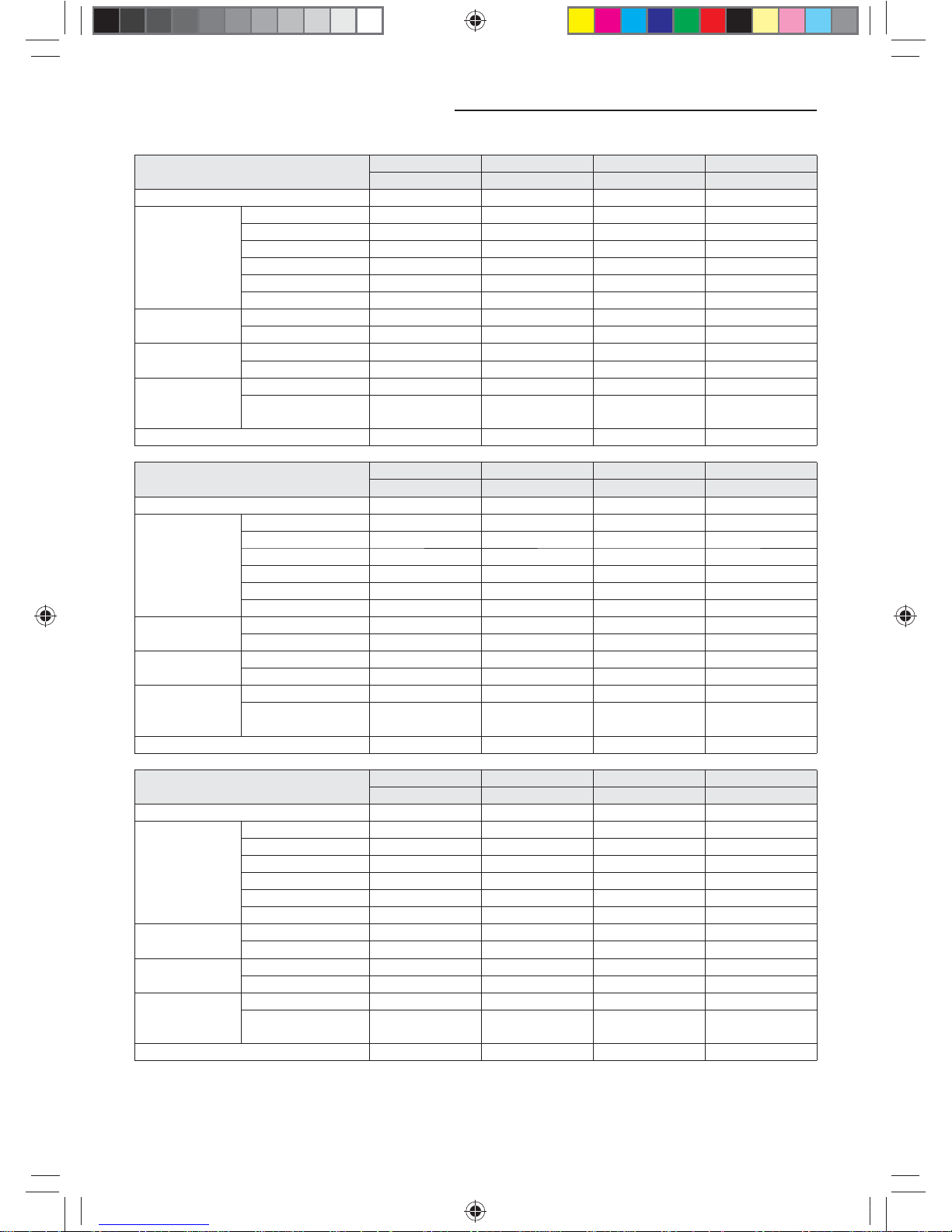
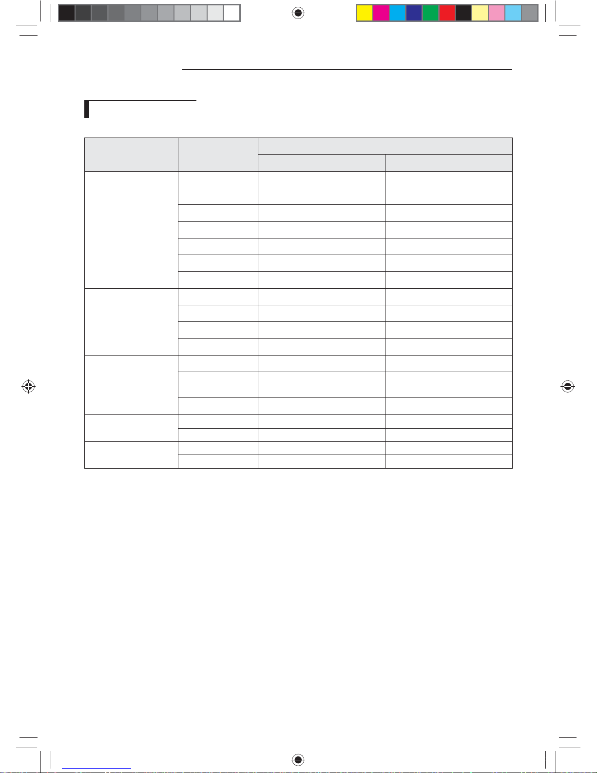
Outdoor unit classication
Classication Small type Large A type Large B type
Appearance
Models
AM✴✴✴F✴ Series AM072✴✴✴ AM096/120/144✴✴✴
AM✴✴✴H✴ Series AM168/192✴✴✴
AM✴✴✴K✴ Series AM072/096✴✴✴ AM216KXVGJ✴
Packaging material disposition
• Safely store or dispose the packaging materials.
- Sharp metals such as nails or wooden material packaging that may break into pieces become a cause for
personal injury.
- Make sure to store or dispose the vinyl type packaging material to keep it out of reach of children. Children
may put them over their face, which is very dangerous since it may lead them to suocation.
CAUTION
k}tGzG㨰䛙G㐘㞬ὤGptluki]_TWZ_XYhTW_UGGG] YWX_TW]TXXGGG㝘䟸G[a[_aYZ
7
ENGLISH
Preparing for installation
Outdoor unit combination
f Make sure to use an indoor unit that is compatible with DVM S.
f Indoor units can be connected within the range indicated in following table.
f If the total capacity of the connected indoor units exceeds the indicated maximum capacity, cooling and heating capacity
of the indoor unit may decrease.
f Total capacity of the connected indoor units can be allowed from 50% to 130% of the total outdoor unit capacity.
0.5 × Σ(Outdoor unit capacity) ≤ Total capacity of the connected indoor units ≤ 1.3 × Σ(Outdoor unit capacity)
❋ You can connect maximum 64 indoor units to the outdoor unit. Maximum quantity of connectable indoor unit is set to 64
since outdoor unit only support up to 64 communication address. Indoor unit address can be assigned from 0~63. If the
indoor unit address was assigned from 64~79, E201 error will occur.
❋ Maximum 32 Wall-mount type indoor units with EEV (AM✴✴✴HNQDC✴) can be connected.
❋ Do not install 1st-generation MCU and 2nd-generation MCU together.
- 1st-generation MCU: MCU-S✴NEE✴N, MCU-S2NEK1N
- 2nd-generation MCU: MCU-S✴NEK2N, MCU-S4NEK3N, MCU-S1NEK1N
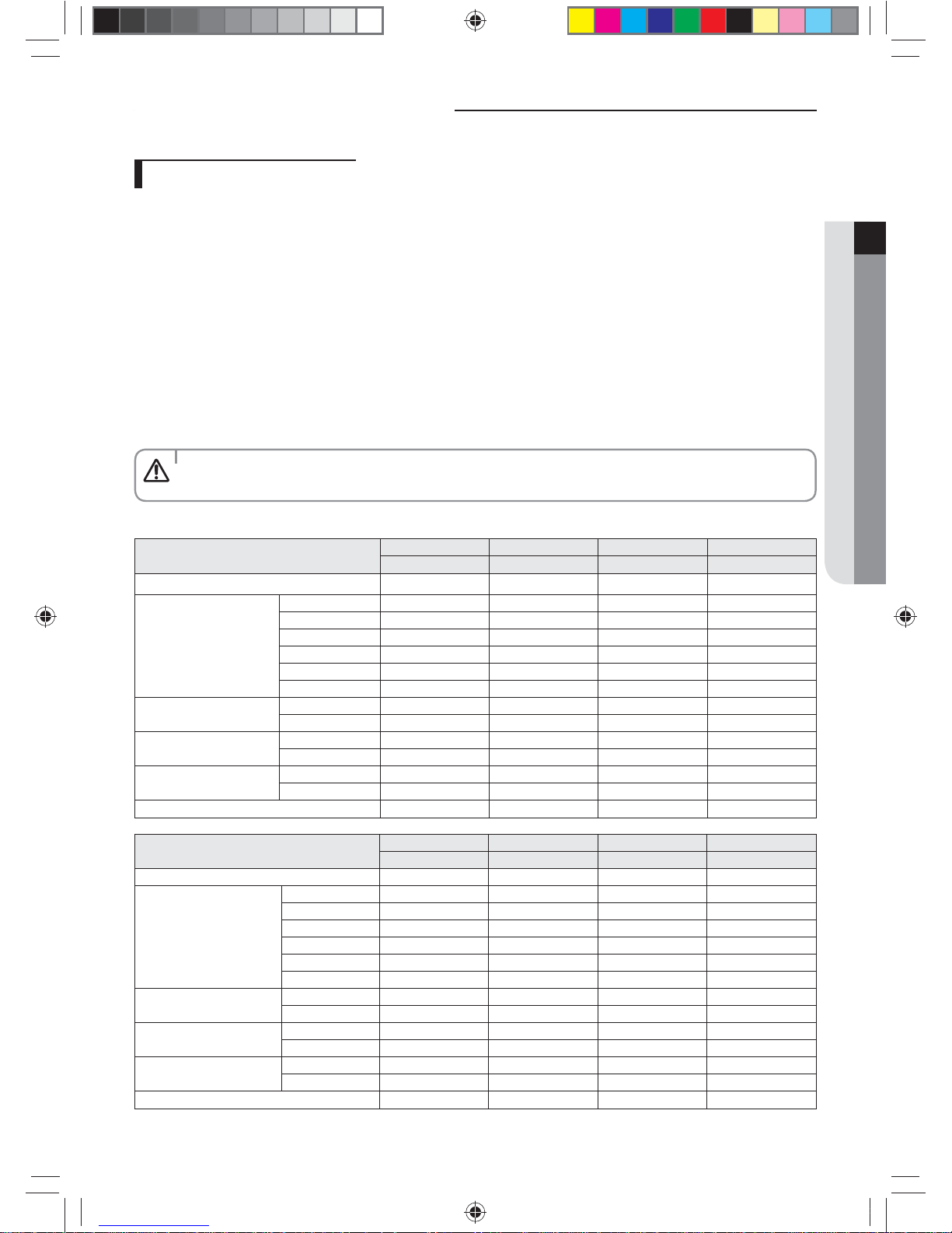
• Use the following table to determine the size and number of outdoor units needed to achieve thecapacity
requirements.
CAUTION
Module combination for AM✴✴✴F✴ Series, AM✴✴✴H✴ Series
Model name for Combination
6TON 8TON 10TON 12TON
AM072FXVA✴✴ AM096FXVA✴✴ AM120FXVA✴✴ AM144FXVA✴✴
Number of individual outdoor units
1111
Combined outdoor unit
AM072✴✴✴
1
AM096✴✴✴
1
AM120✴✴✴
1
AM144✴✴✴
1
AM168✴✴✴
AM192✴✴✴
Nominal Capacity
Cooling(btu/h)
72000 96000 120000 144000
Heating(btu/h)
81000 108000 135000 162000
Rated Capacity
Cooling(btu/h)
69000 92000 114000 138000
Heating(btu/h)
77000 103000 129000 154000
Total capacity of the connected
indoor units (cooling)
Minimum(btu/h)
36000 48000 60000 72000
Maximum(btu/h)
93600 124800 156000 187200
Maximum number of connectable indoor units
12 16 20 25
Model name for Combination
14TON 16TON 18TON 20TON
AM168HXVA✴✴ AM192HXVA✴✴ AM216JXVA✴✴ AM240JXVA✴✴
Number of individual outdoor units
1122
Combined outdoor unit
AM072✴✴✴
11
AM096✴✴✴
AM120✴✴✴
AM144✴✴✴
1
AM168✴✴✴
11
AM192✴✴✴
1
Nominal Capacity
Cooling(btu/h)
168000 192000 216000 240000
Heating(btu/h)
189000 216000 243000 270000
Rated Capacity
Cooling(btu/h)
160000 184000 206000 228000
Heating(btu/h)
180000 206000 230000 258000
Total capacity of the connected
indoor units(cooling)
Minimum(btu/h)
84000 96000 108000 120000
Maximum(btu/h)
218400 249600 280800 312000
Maximum number of connectable indoor units
29 33 37 41
k}tGzG㨰䛙G㐘㞬ὤGptluki]_TWZ_XYhTW_UGGG^ YWX_TW]TXXGGG㝘䟸G[a[_aYZ
8
Preparing for installation
Model name for Combination
22TON 24TON 26TON 28TON
AM264JXVA✴✴ AM288JXVA✴✴ AM312JXVA✴✴ AM336JXVA✴✴
Number of individual outdoor units
2222
Combined outdoor
unit
AM072✴✴✴
1
AM096✴✴✴
AM120✴✴✴
AM144✴✴✴
21
AM168✴✴✴
12
AM192✴✴✴
1
Nominal Capacity
Cooling(btu/h)
264000 288000 312000 336000
Heating(btu/h)
297000 324000 351000 378000
Rated Capacity
Cooling(btu/h)
252000 276000 298000 320000
Heating(btu/h)
282000 308000 334000 360000
Total capacity of the
connected indoor
units(cooling)
Minimum(btu/h)
132000 144000 156000 168000
Maximum(btu/h)
343200 374400 405600 436800
Maximum number of connectable indoor units
45 49 54 58
Model name for Combination
30TON 32TON 34TON 36TON
AM360JXVA✴✴ AM384JXVA✴✴ AM408JXVA✴✴ AM432JXVA✴✴
Number of individual outdoor units
2233
Combined outdoor
unit
AM072✴✴✴
1
AM096✴✴✴
AM120✴✴✴
AM144✴✴✴
13
AM168✴✴✴
1
AM192✴✴✴
121
Nominal Capacity
Cooling(btu/h)
360000 384000 408000 432000
Heating(btu/h)
405000 432000 459000 486000
Rated Capacity
Cooling(btu/h)
344000 366000 390000 415000
Heating(btu/h)
386000 410000 435000 460000
Total capacity of the
connected indoor
units(cooling)
Minimum(btu/h)
180000 192000 204000 216000
Maximum(btu/h)
468000 499200 530400 561600
Maximum number of connectable indoor units
62 64 64 64
Model name for Combination
38 TON 40 TON 42 TON 44 TON
AM456JXVA✴✴ AM480JXVA✴✴ AM504JXVA✴✴ AM528JXVA✴✴
Number of individual outdoor units
3333
Combined outdoor
unit
AM072✴✴✴
AM096✴✴✴
AM120✴✴✴
1
AM144✴✴✴
1
AM168✴✴✴
2232
AM192✴✴✴
1
Nominal Capacity
Cooling(btu/h)
456000 480000 504000 528000
Heating(btu/h)
513000 540000 567000 594000
Rated Capacity
Cooling(btu/h)
435000 455000 480000 500000
Heating(btu/h)
490000 510000 535000 560000
Total capacity of the
connected indoor
units(cooling)
Minimum(btu/h)
228000 240000 252000 264000
Maximum(btu/h)
592800 624000 655200 686400
Maximum number of connectable indoor units
64 64 64 64
k}tGzG㨰䛙G㐘㞬ὤGptluki]_TWZ_XYhTW_UGGG_ YWX_TW]TXXGGG㝘䟸G[a[_aYZ
9
ENGLISH
f Module combination for AM192H✴✴✴J✴ , AM216K✴✴✴J✴
Model name for Combination
18 TON 34 TON 36 TON
AM216KXVGJ✴ AM408KXVGJ✴ AM432KXVGJ✴
Number of individual outdoor units
122
Combined outdoor
unit
AM192H✴✴✴J✴
(Large A type)
1
AM216K✴✴✴J✴
(Large B type)
112
Nominal Capacity
Cooling(btu/h)
216000 408000 432000
Heating(btu/h)
243000 459000 486000
Rated Capacity
Cooling(btu/h)
206000 390000 415000
Heating(btu/h)
230000 435000 460000
Total capacity of
the connected
indoor
units(cooling)
Minimum(btu/h)
108000 204000 216000
Maximum(btu/h)
280800 530400 561600
Maximum number of connectable indoor units
37 64 64
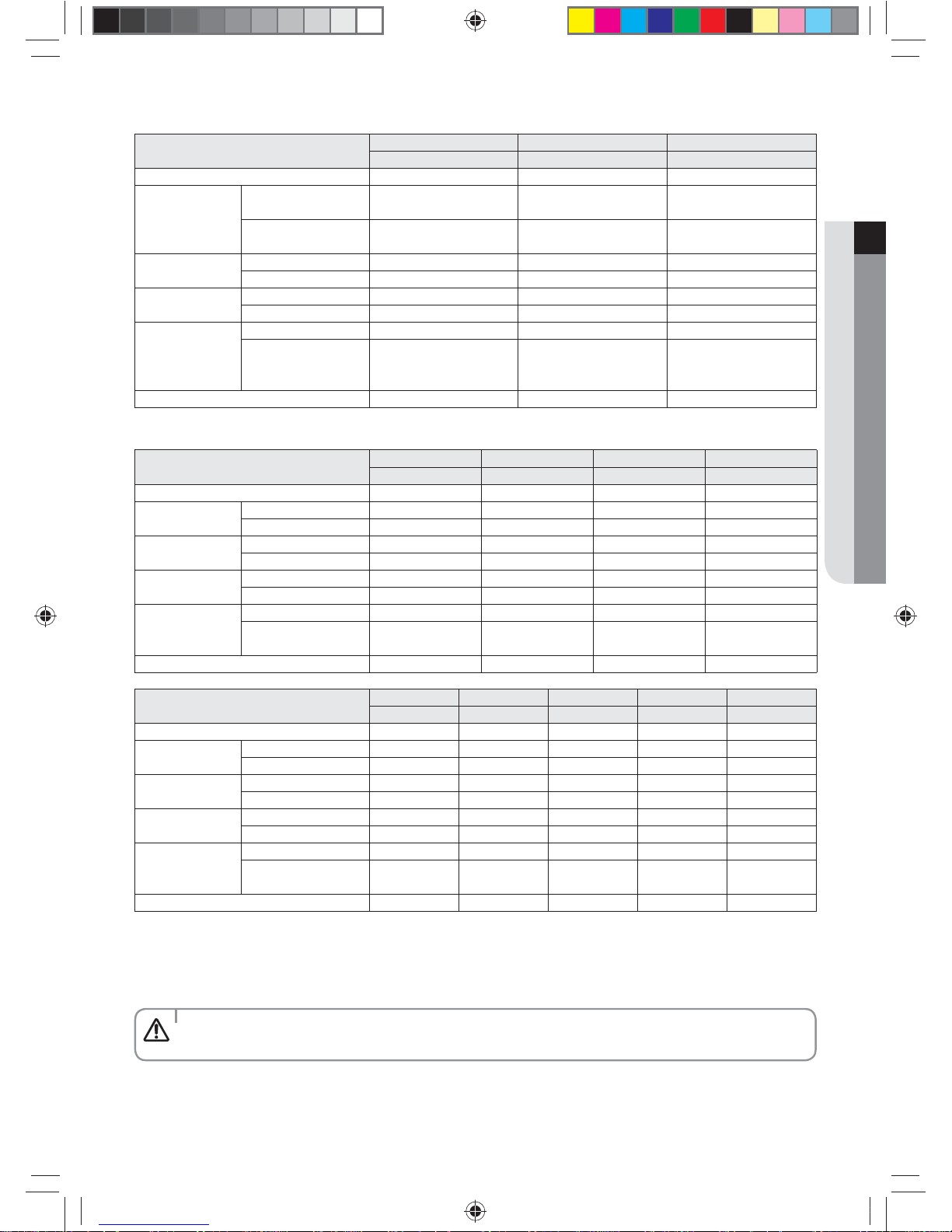
f Module combination for AM✴✴✴K✴ Series
Model name for Combination
6 TON 8 TON 12 TON 14 TON
AM072KXVT✴✴ AM096KXVT✴✴ AM144KXVT✴✴ AM168KXVT✴✴
Number of individual outdoor units
1122
Combined outdoor
unit
AM072✴✴✴
121
AM096✴✴✴
11
Nominal Capacity
Cooling(btu/h)
72000 96000 144000 168000
Heating(btu/h)
81000 108000 162000 189000
Rated Capacity
Cooling(btu/h)
69000 92000 138000 160000
Heating(btu/h)
77000 103000 154000 180000
Total capacity of the
connected indoor
units(cooling)
Minimum(btu/h)
36000 48000 72000 84000
Maximum(btu/h)
93600 124800 187200 218400
Maximum number of connectable indoor units
12 16 25 29
Model name for Combination
16 TON 18 TON 20 TON 22 TON 24 TON
AM192KXVT✴✴ AM216KXVT✴✴ AM240KXVT✴✴ AM264KXVT✴✴ AM288KXVT✴✴
Number of individual outdoor units
23333
Combined outdoor
unit
AM072✴✴✴
321
AM096✴✴✴
2123
Nominal Capacity
Cooling(btu/h)
192000 216000 240000 264000 288000
Heating(btu/h)
216000 243000 270000 297000 324000
Rated Capacity
Cooling(btu/h)
184000 206000 228000 252000 276000
Heating(btu/h)
206000 230000 258000 282000 308000
Total capacity of the
connected indoor
units(cooling)
Minimum(btu/h)
96000 108000 120000 132000 144000
Maximum(btu/h)
249600 280800 312000 343200 374400
Maximum number of connectable indoor units
33 37 41 45 49
❋ You can connect maximum 64 indoor units to the outdoor unit. Maximum quantity of connectable indoor unit is set to 64
since outdoor unit only support up to 64 communication address. Indoor unit address can be assigned from 0~63. If the
indoor unit address was assigned from 64~79, E201 error will occur.
❋ Minimum capacity of the indoor unit is 6.0 MBH.
• Installation combination must be complied when composing outdoor unit combination.
CAUTION
k}tGzG㨰䛙G㐘㞬ὤGptluki]_TWZ_XYhTW_UGGG` YWX_TW]TXXGGG㝘䟸G[a[_aY[
10
Preparing for installation
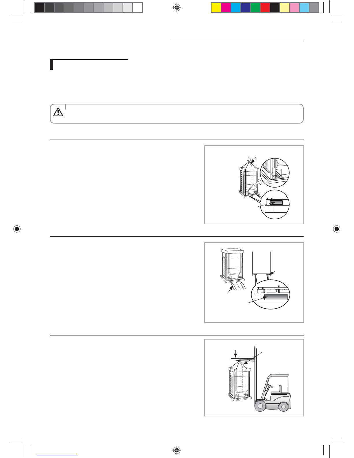
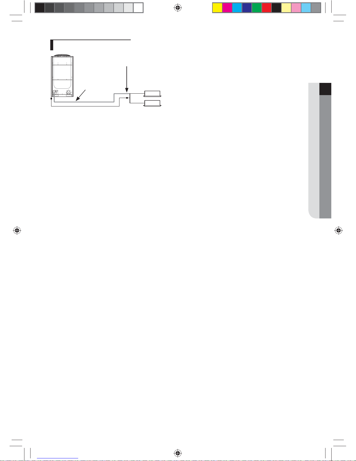
Moving the outdoor unit
f Select the moving path in advance.
f Be sure that moving path can support weight of the outdoor unit.
f Do not slant the product more than 30˚ when carrying it. (Do not lay the product down in sideways.)
f Surface of the heat exchanger is sharp. Be careful not to get injured while moving the product.
• You must use certain part of the product when moving the product.
CAUTION
When moving with a crane
f Fasten the wire rope as shown in the gure.
f To protect damage or scratches, insert a piece of cloth between the
outdoor unit and the wire rope.
Wire rope
Holes for wire rope to go
through
When moving with a forklift
f Carefully insert the forklift forks into the forklift holes at the bottom of
the outdoor unit.
f Be careful with the forklift from damaging the product.
Forklift
Forklift holes
Holes for forklift forks
to go through
When moving the product without wooden pallet and the crane is not available for use
f Connect a wire rope to the outdoor unit as you would move it with a
crane.
f Hang the wire rope to the forklift fork to move the outdoor unit.
Wire rope
Forklift
k}tGzG㨰䛙G㐘㞬ὤGptluki]_TWZ_XYhTW_UGGGXW YWX_TW]TXXGGG㝘䟸G[a[_aY[
11
ENGLISH
Selecting installation location
Decide the installation location, with the consideration of the following conditions, under user’s approval.
f Place where hot discharge air or noise from the outdoor unit may not disturb the neighbor (Especially in residential areas,
keep the operation hours in mind.)
f Place where structure can bear the weight and vibration of the outdoor unit.
f Place with at surface where rainwater does not settle or leak.
f Place where it is not exposed to strong wind.
f Well ventilated place with sucient service place for repairs and maintenance. (Discharge duct can be purchased
separately)
f Place where you can connect the refrigerant pipes between indoor and outdoor units within allowable distance.
f Place where it allows easy waterproong and draining work for the condensation water generated from the outdoor unit
during heating operation.
f Place where there is no risk of inammable gas leakage.
f Place where there is no direct inuence of snow or rain.
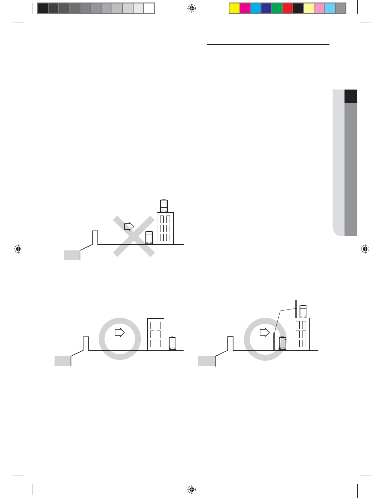
f Do not install the product in a place where it will be directly exposed to sea breeze.
- Consult an installation expert (or company) since you will need to take extra anti-corrosion measures if you need to
install the product in a place where it can be exposed to direct sea breeze. (You have to remove dusts and salinity on
the heat exchanger and apply designated rust inhibitor more than once a year.)
Sea
Sea breeze
Outdoor
unit
Outdoor
unit
❋ Caution when installing the product in seashore
- When installing the product in seashore, make sure to install it behind a structure (such as building) that can block the
sea breeze or install protection wall around the outdoor unit.
- Make sure to install the product in a place where it allows smooth drainage.
Protection wall should be constructed with a solid material that
can block the sea breeze and the height and width of the wall
should be 1.5 times larger than the size of the outdoor unit. (You
must secure more than 700mm(28inch) of space between the
protection wall and the outdoor unit for air circulation.)
Sea
Sea breeze
Outdoor
unit
Protection wall
Outdoor unit
Sea
Sea breeze
Outdoor
unit
k}tGzG㨰䛙G㐘㞬ὤGptluki]_TWZ_XYhTW_UGGGXX YWX_TW]TXXGGG㝘䟸G[a[_aY[
12
Selecting installation location
• System air conditioner may cause static noise when listening to AM stations. Therefore, select an installation
location for indoor unit where electrical wiring can be done while keeping certain distance from a radio,
computer and stereo equipment.
- Especially, keep the unit at least 3m(9.84inch) away from the electrical equipment in an area with weak
electromagnetic waves and put the main power cable and communication cables in a separately installed
protection tube.
- Make sure that there is no equipment that generates electromagnetic waves. If not electromagnetic waves
may cause problem to the control systems which may lead to air conditioner malfunction. (Example: Remote
control sensor of the indoor unit may not receive the signal very well, due to ballast stabilizer of the lighting
equipment.)
• In regions with heavy snowfall, make sure to install the outdoor unit where there is no concerns of direct
snowfall on the outdoor unit. Also, build higher base support so that accumulated snow does not block the air
inlet or the heat exchanger.
• R-410A refrigerant is a safe, nontoxic and nonammable refrigerant. However, if the place holds any concerns for
exceeding dangerous level of refrigerant concentration in case of refrigerant leakage, extra ventilation system is
required.
• When you install the outdoor unit in a high places such as roof, install fence or guardrail around it. When there is
no fence or guardrail, service person could fall.
• Do not install the product in places where corrosive gases such as sulfur oxides, ammonia, and sulfurous gas are
produced. (e.g. Toilet outlet, ventilation opening, sewage works, dyeing complex, cattle shed, sulfuric hot spring,
nuclear power plant, ship etc.) When installing the product in those places, contact an installation specialty
store as the copper pipe and brazing part will need additional corrosion proof or anti-rust additive to prevent
corrosion.
• Make sure to keep away inammable materials (such as wooden materials, oil etc.) around the outdoor unit.
When there's re, those inammable material will easily catch the re and may pass it on to the product.
• Depending on the condition of power supply, unstable power or voltage any cause malfunction of the parts or
control system. (At the ship or places using power supply from electric generator...etc)
• Make sure to install MCU when using HR products.
• When you select the location to install MCU, the location is far away from indoor rooms because the refrigerant
running of MCU may create noise.
CAUTION
k}tGzG㨰䛙G㐘㞬ὤGptluki]_TWZ_XYhTW_UGGGXY YWX_TW]TXXGGG㝘䟸G[a[_aY[
13
ENGLISH
Space requirement for installation
f Space requirement was decided based on following conditions; Cooling mode, outdoor temperature of 35°C (95°F).
Larger space is required if the outdoor temperature is higher than 35°C (95°F) or if the place is heated easily by quantity of
solar radiation.
f When you secure installation space, consider path for people and the direction of the wind.
f Secure installation space as shown in the below illustration, considering ventilation and the service space.
f If the installation space is narrow, installer or other worker may get injured during work and may also cause problem to
the product.
f If you install multiple number of outdoor units in one space, make sure to secure enough ventilation space if there’s
any walls around the product that may disturb the air ow. If enough ventilation space is not secured, product may
malfunction.
f You may install the outdoor units with 20mm (0.78 inch) of space between the product, but product’s performance may
decrease depending on the installation environment.
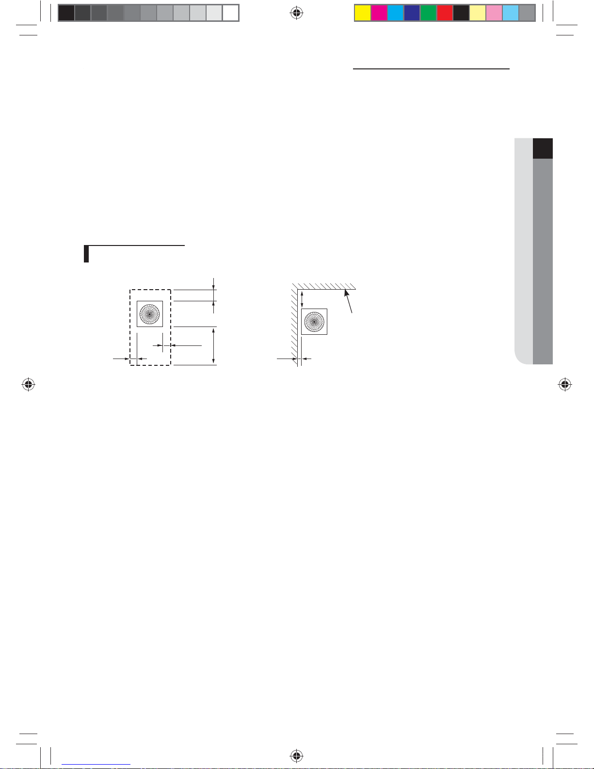
Single installation
Unit: mm (inch)
Height of the wall is
unlimited
Over 100 (4)
[S2]
Over 500 (20)
[S1]
Over 100 (4) Over 100 (4)
Front
side
Over 100 (4)
Over 300 (12)
<Case 1> <Case 2>
Front side
k}tGzG㨰䛙G㐘㞬ὤGptluki]_TWZ_XYhTW_UGGGXZ YWX_TW]TXXGGG㝘䟸G[a[_aY[
14
Space requirement for installation
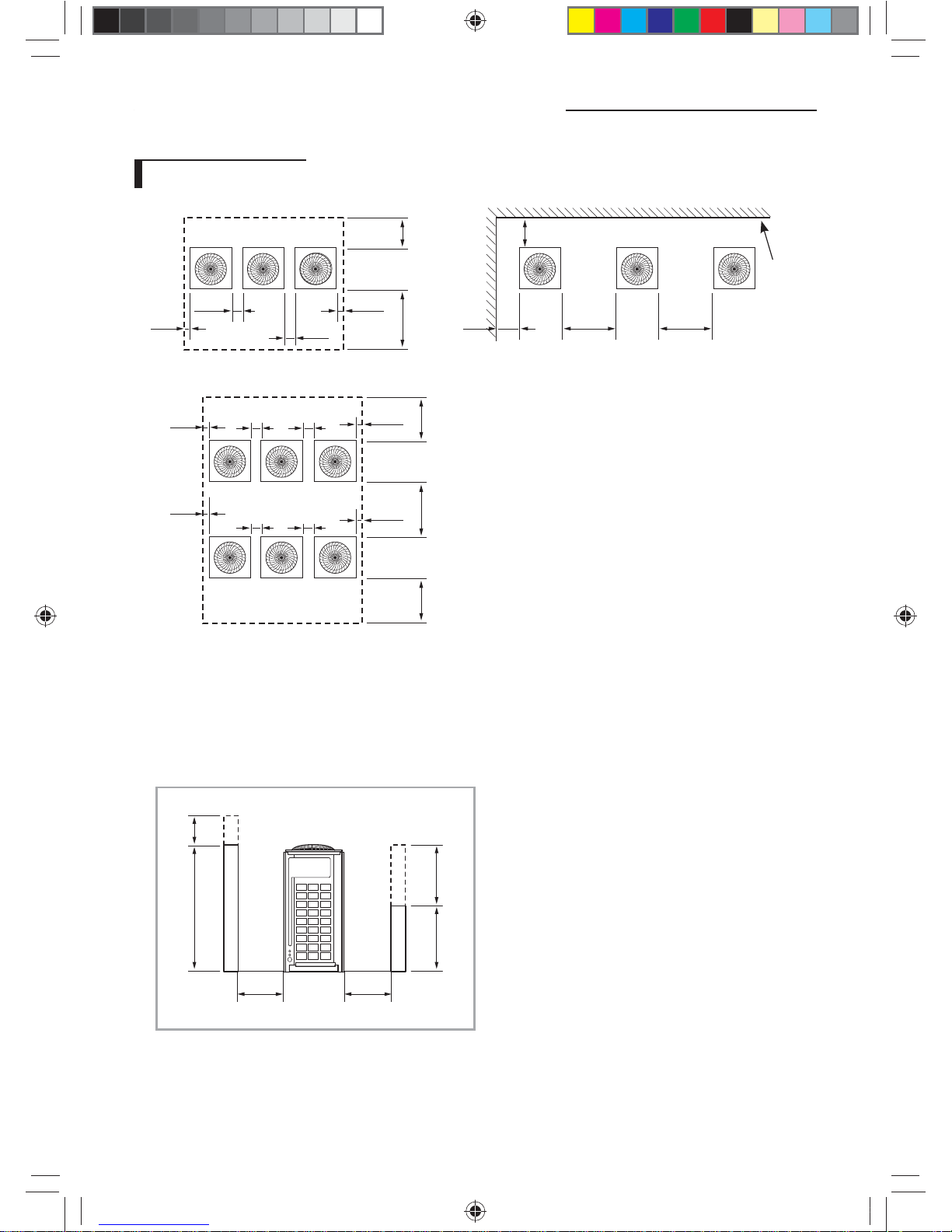
Module installation
<Case 3>
Over 500
(20)
Over 500
(20)
Over 600
(24)
Over 100 (4) Over 100 (4)
Over 100 (4)
Over 100 (4)
Over 100 (4) Over 100 (4) Over 100 (4)
Over 100 (4)
Front side
Front side
<Case 1> <Case 2>
Over 200 (8)
Over 100 (4)
Over 300 (12)
[S2]
Over 500
(S1)
Over 100 (4)
Over 100 (4)
Over 100 (4)
Over 300 (12)
Over 400
(16)
Over 400
(16)
Height of
the wall is
unlimited
Front
side
Front side
❋ For <Case 1> or <Case 3>
• Height of the wall on the front side should not be higher than 1500mm (60 inch).
• Height of the wall on the air inlet side should not be higher than 500mm (20 inch).
• Height of the wall on the side is not limited.
• If the height of the wall exceeds by certain value (h1, h2), additional clearance [(h1)/2, (h2)/2 : Half of the exceeded
distance] should be added to the service space (S1, S2).
1500 (60) h1
500 (20) h2
Front side
Air inlet side
Unit: mm (inch)
S1+h1/2 S2+h2/2
k}tGzG㨰䛙G㐘㞬ὤGptluki]_TWZ_XYhTW_UGGGX[ YWX_TW]TXXGGG㝘䟸G[a[_aY[
15
ENGLISH
Accessories
Accessories
f You must keep following accessories until the installation is nished.
f Hand over the installation manual to the customer after nishing the installation.
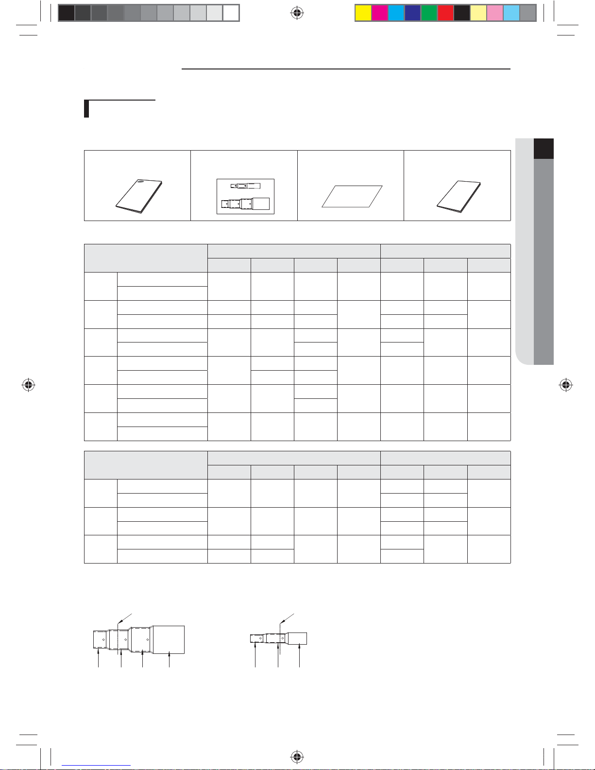
Installation manual (1) *Installation socket (1) Brand Label (1) Instruction sheet (1)
❋ Models with installaton socket
MODEL
(AM✴✴✴F✴, AM✴✴✴H✴ Series)
HR HP
GAS LIQUID HIGH GAS SOCKET GAS LIQUID SOCKET
6TON
Pipe in Production
3/4" 3/8" 5/8" X 3/4" 3/8" X
Installaton Pipe
8TON✴
Pipe in Production 1-1/8" 1/2" 7/8"
O
1" 1/2"
O
Installaton Pipe 7/8" 3/8" 3/4" 7/8" 3/8"
10TON
Pipe in Production
1-1/8" 1/2"
7/8"
O
1"
1/2" O
Installaton Pipe 3/4" 1-1/8"
12TON
Pipe in Production
1-1/8"
5/8" 1-1/8"
O 1-1/8" 1/2" X
Installaton Pipe 1/2" 7/8"
14TON
Pipe in Production
1-1/8" 5/8"
1-1/8"
O 1-1/8" 5/8" X
Installation Pipe 7/8"
16TON
Pipe in Production
1-1/8" 5/8" 1-1/8" X 1-1/8" 5/8" X
Installation Pipe
MODEL (AM✴✴✴K✴ Series)
HR HP
GAS LIQUID HIGH GAS SOCKET GAS LIQUID SOCKET
6TON✴
Pipe in Production
----
1-1/8" 1/2"
O
Installaton Pipe 3/4" 3/8"
8TON✴
Pipe in Production
----
1-1/8" 5/8"
O
Installaton Pipe 7/8" 3/8"
18TON✴
Pipe in Production 1-3/8" 3/4"
1-1/8" O
1-3/8"
5/8" O
Installaton Pipe 1-1/8" 5/8" 1-1/8"
EX) Cut the scoket for high gas pipe and liquid pepe (In case of 8TON HR)
ID3/4" ID7/8" ID 1 1/8" OD 1 3/8"
cutting line cutting line
Socket for Gas and High gas pipe
ID3/8" ID1/2" ID 5/8"
Socket for Liquid pipe
k}tGzG㨰䛙G㐘㞬ὤGptluki]_TWZ_XYhTW_UGGGX\ YWX_TW]TXXGGG㝘䟸G[a[_aY\
16
Accessories
Optional accessories
f Following optional accessories are needed for connecting pipes between the indoor and outdoor units.
Classication Model Name
Specication
MBH KW
Y-Joint
MXJ-YA1509M 51 below 15.0 and below
MXJ-YA2512M Over 51~136 and below Over 15.0 ~40.0 and below
MXJ-YA2812M Over 136~154 and below Over 40.0 ~45.0 and below
MXJ-YA2815M Over 154~240 and below Over 45.0 ~70.3 and below
MXJ-YA3419M Over 240~336 and below Over 70.3 ~98.4 and below
MXJ-YA4119M Over 336~461 and below Over 98.4 ~135.2 and below
MXJ-YA4422M Over 461 Over 135.2
Y-Joint (Only H/R)
MXJ-YA1500M 76 and below 22.4 and below
MXJ-YA2500M Over 76~240 and below Over 22.4 ~70.3 and below
MXJ-YA3100M Over 240~461 and below Over 70.3 ~135.2 and below
MXJ-YA3800M Over 461 Over 135.2
Distribution header
MXJ-HA2512M 154 and below (for 4 rooms) 45.0 and below (for 4 rooms)
MXJ-HA3115M
Over 240 ~ 461 and below
(for 8 rooms)
Over 70.3 ~ 135.2 and below
(for 8 rooms)
MXJ-HA3819M Over 240 (for 8 rooms) Over 70.3 (for 8 rooms)
Y-Joint
- Outdoor unit
MXJ-TA3819M 461 and below 135.2 and below
MXJ-TA4422M 478.4 and over 140.2 and over
Y-Joint (Only H/R)
- Outdoor unit
MXJ-TA3100M 461.3 and below 135.2 and below
MXJ-TA3800M 478.4 and over 140.2 and over
❋ If you use an indoor unit with no internal EEV(Electric Expansion Valve), you will need an EEV kit.
❋ Only use the genuine accessories listed in above table and do not use imitated accessories.
k}tGzG㨰䛙G㐘㞬ὤGptluki]_TWZ_XYhTW_UGGGX] YWX_TW]TXXGGG㝘䟸G[a[_aY\
17
ENGLISH
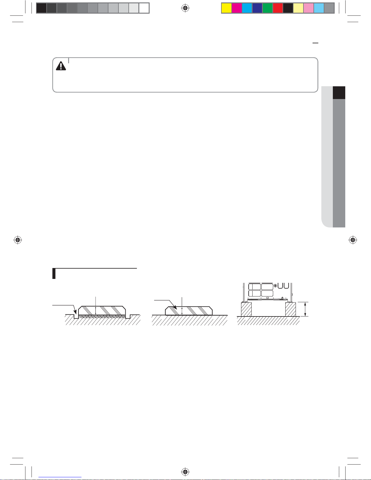
Base construction and installation of the outdoor unit
• Make sure to remove the wooden pallet before installing the outdoor unit. If you do not remove the wooden
pallet, there is risk of re during welding the pipes. If the outdoor unit is installed with wooden pallet on, and
it was used for long period time, wooden palette may break and cause electrical hazard or high pressure may
damage the pipes.
WARNING
❋ Fix an outdoor unit rmly on the base ground with anchor bolts.
❋ Manufacturer is not responsible for the damage occurred by not following the installation standards.
1. Make sure that the height of the base ground is 200mm or higher to protect the outdoor unit from rain water or other
external conditions. Also, install a draining pit around the base ground and connect the drain pipe to the drainage.
2. Considering the vibration and weight of the outdoor unit, strength of the base ground must be strong to prevent noise
and the top surface of it should be at.
3. Base ground should be 1.5 times larger than the bottom of the outdoor unit.
4. Outdoor unit must be xed rmly so that it can withstand the wind speed of 30m/s. If you cannot x the outdoor unit on
the base ground, x it by side or use extra structure.
5. In heating operation, defrost water may form so you must really care about the drainage and waterproong the oor. To
prevent defrost water from stagnating or freezing, construct a drainage with over 1/50 slope. (Ice may form on the oor
in winter time.)
6. It is necessary to add wire mesh or steel bar during concrete construction for the base ground to prevent damages or
cracks.
7. When installing multiple outdoor units at the same place, construct a H beam or an anti-vibration frame on the base
ground to install the outdoor unit.
8. After installing a H beam or an anti-vibration frame, apply corrosion protection and other necessary coating.
9. When concrete construction for outdoor unit installation is completed, install an anti-vibration pad (t=20mm/0.78 inch or
more) or an anti-vibration frame to prevent vibration of the outdoor unit from transferring to the base ground.
10. Place the outdoor unit on a H beam or an anti-vibration frame and x it with the bolt, nut and washer. (The bearing force
has to be over 3.5kN)
Base ground construction
<When installing on the ground>
Draining pit
Over 200mm (8inch)
<When installing on the roof>
Bottom surface of the base
ground must be horizontally
leveled
Over 200mm (8inch)
Over 200mm (8inch)
k}tGzG㨰䛙G㐘㞬ὤGptluki]_TWZ_XYhTW_UGGGX^ YWX_TW]TXXGGG㝘䟸G[a[_aY\
18
Base construction and installation of the outdoor unit
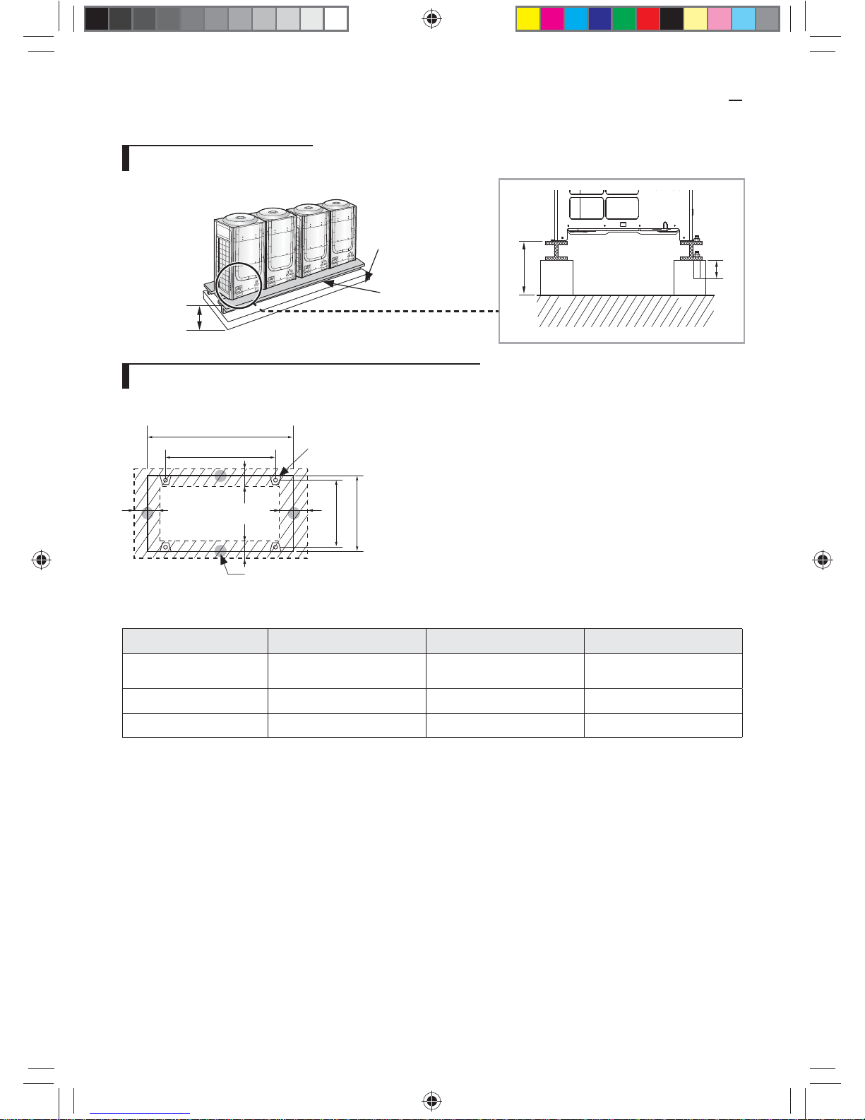
Outdoor unit installation
Over 200mm (8inch)
Over 50mm (2inch)
Base ground
H beam or anti-vibration
frame
Over 200mm
(8inch)
Outdoor unit base mount and anchor bolt position
Unit: mm (inch)
A
B
54
(2.13)
761 (29.96)
803 (31.61)
54
(2.13)
Outdoor unit - Anti-vibration
frame (4-Ø 12)
Anti-vibration - Base ground
(4-Ø 18)
Unit: mm (inch)
Classication Small type Large A type Large B type
Models AM072F✴
AM096/120/144F✴,
AM168/192H✴, AM072/096K✴
AM216KXVGJ✴
A 880 (34.65) 1,295 (50.98) 1,295 (50.98)
B 740 (29.13) 1,150 (45.28) 1,150 (45.28)
❋ Refer to the blueprints in technical data book to make a holes for connecting the anti-vibration pad.
k}tGzG㨰䛙G㐘㞬ὤGptluki]_TWZ_XYhTW_UGGGX_ YWX_TW]TXXGGG㝘䟸G[a[_aY\
19
ENGLISH
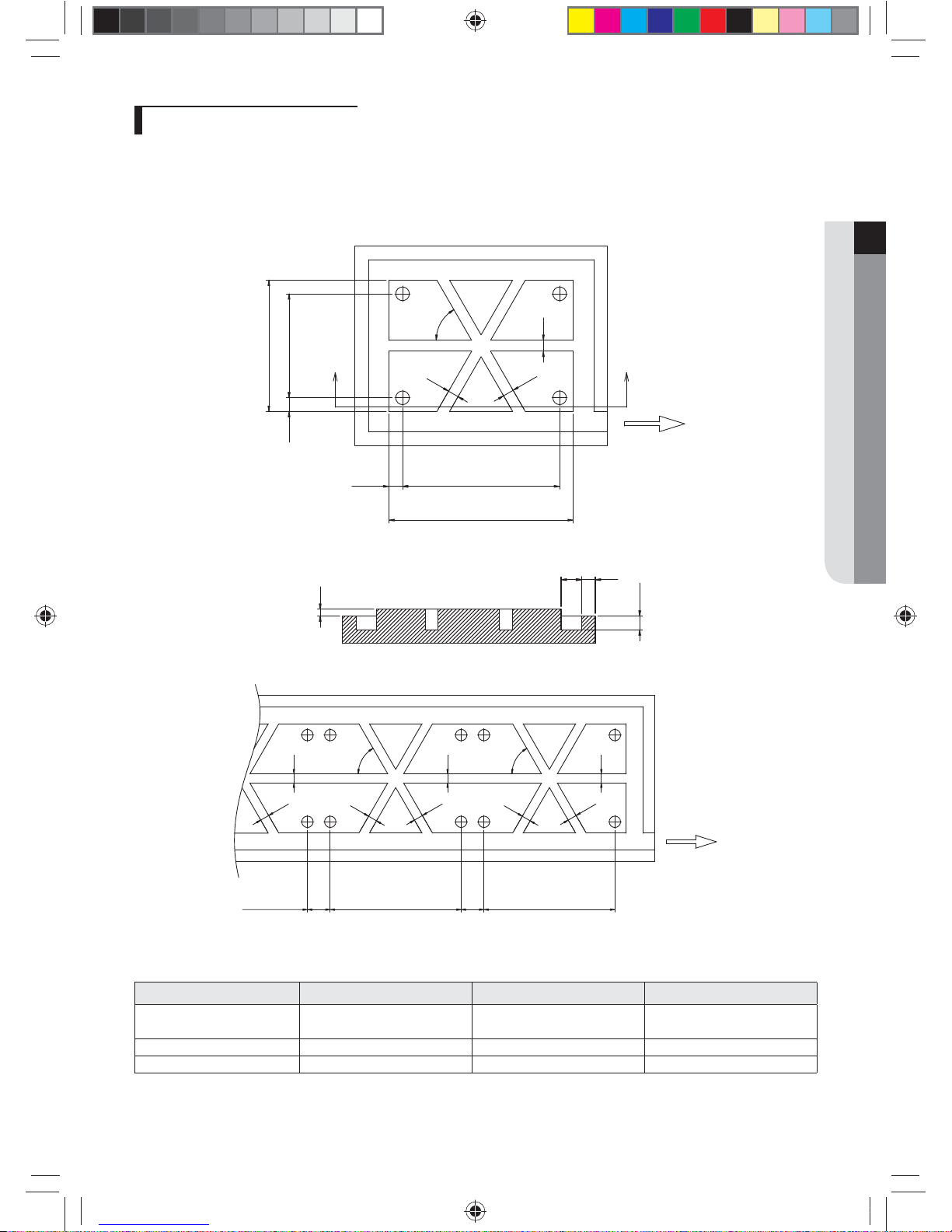
Examples of draining work
f Construct the drainage ditch with reinforced concretes and make sure that water-proong work is done.
f For smooth draining of defrost water, make sure to apply 1/50 slope.
f Construct a drainage around the outdoor unit to prevent the defrost water (from the outdoor unit) from stagnating,
overowing or freezing near the installation space.
f When the outdoor unit is installed on the roof, check the strength and waterproof status of the roof.
Unit: mm (inch)
960 (37.80)
760 (29.92)
100 (3.94)
80 (3.15)
80 (3.15)
80 (3
.
15)
60°
100 (3.94)
X
X’
Direction of the drainage
(Slope 1/50)
<Drainage work for single installation>
B
A
50 (1.97)
100
(3.94)
150 (5.91) 100 (3.94)
<X-X’ SECTION>
80 (3.15)
80 (3.15)
80 (3.15)
80 (3.15)
80 (3.15)
80 (3.15)
80 (3.15)
80 (3.15)
60°
60°
200
(7.87)
BB
200
(7.87)
Direction of the drainage
(Slope 1/50)
<Drainage work for module installation>
Unit: mm (inch)
Classication Small type Large A type Large B type
Models AM072F✴
AM096/120/144F✴,
AM168/192H✴, AM072/096K✴
AM216KXVGJ✴
A 940 (37.01) 1,350 (53.15) 1,350 (53.15)
B 740 (29.13) 1,150 (45.28) 1,150 (45.28)
k}tGzG㨰䛙G㐘㞬ὤGptluki]_TWZ_XYhTW_UGGGX` YWX_TW]TXXGGG㝘䟸G[a[_aY\
20
Base construction and installation of the outdoor unit
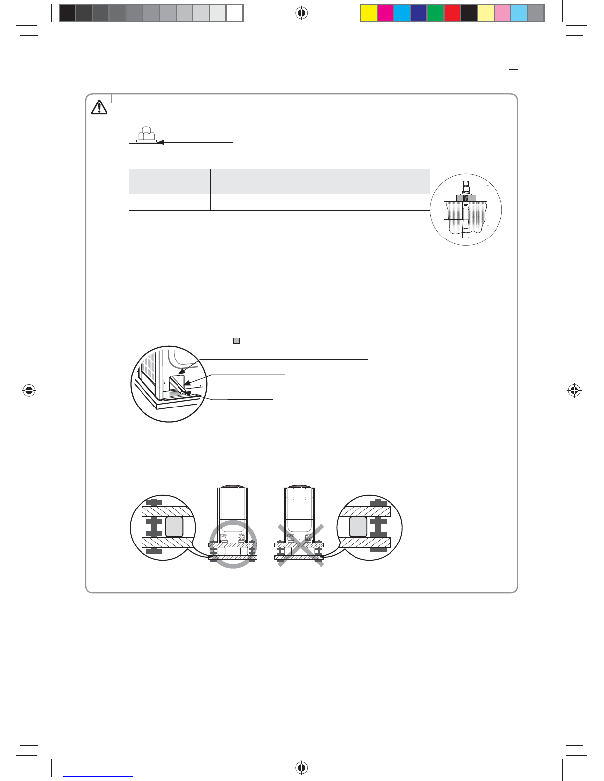
Cautions regarding on connecting the anchor bolt
f Tighten the rubber washer to prevent the bolt connection part of the outdoor unit from corroding.
Rubber washer
f Anchor specication
Size
Diameter of
drill bit (a)
Anchor length
(b)
Sleeve length
(b)
Insert depth
Fastening
torque
B
C
D
N
Ø 10 14mm (1/2") 75mm (3") 40mm (1-1/2") 50mm (2") 30 N·m
❋ Use the anchor bolts and nuts that is zinc plated or made of STS material. Regular
anchor bolts or nuts may get damaged by corrosion.
Cautions regarding on connecting the pipe
f If you install the outdoor unit on the rooftop, check the strength and make sure to waterproof the rooftop.
f Construct draining pit around the base construction and pay attention to the drainage around the outdoor
unit. (Condensation or defrost water may form during outdoor unit operation.)
f If there's any possibility of small animals from entering the pipe outlet, block the outlet as shown in the
illustration.
Liquid side pipe
Gas side pipe
Block the
part. (When withdrawing the pipe from
the front side)
Cautions regarding on anti-vibration frame installation
f During installation, make sure there is no gap between the base ground and the supporting structures such as
anti-vibration frame or H beam.
f Base ground must be constructed strongly to support the bottom part of the anti-vibration mount.
f After installing the anti-vibration frame, untighten the xing part on the top and bottom part of the frame.
CAUTION
k}tGzG㨰䛙G㐘㞬ὤGptluki]_TWZ_XYhTW_UGGGYW YWX_TW]TXXGGG㝘䟸G[a[_aY]
21
ENGLISH
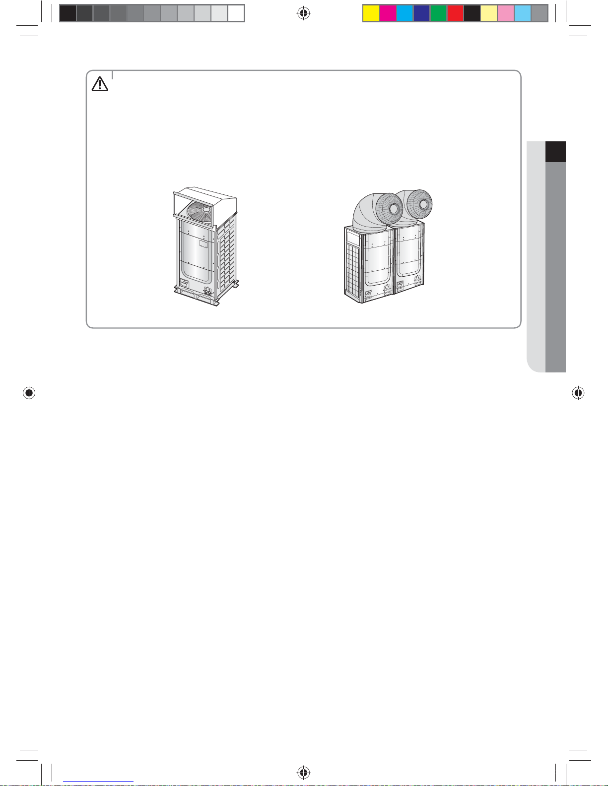
Caution for installing discharge duct
f Static pressure of the discharge duct should be within the standard specication 78.45 Pa (0.315 W.G) when
installing the duct.
f If you remove the fan guard to install the discharge duct, make sure to install a safety net on the duct outlet.
Foreign substance may enter into the product and there could be a risk of personal injury.
f Wear protection equipment at all times when making galvanized sheet metal duct, since the worker may get
injured by the sharp parts.
f When installing the outdoor unit under the tree or near forest, leafs may get into the product and cause
problems on the product. Therefore, install a discharge duct to prevent foreign substance inltration.
<Protecting discharge duct> <Preventing foreign substance inltration>
CAUTION
k}tGzG㨰䛙G㐘㞬ὤGptluki]_TWZ_XYhTW_UGGGYX YWX_TW]TXXGGG㝘䟸G[a[_aY]
22
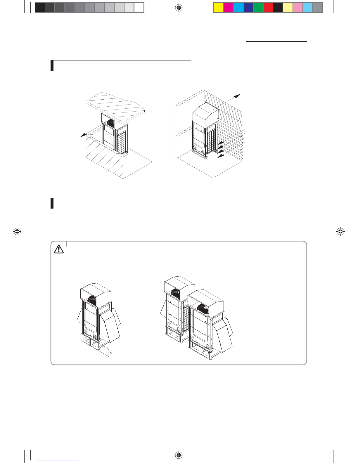
Installing the wind/snow prevention duct
Installing the outdoor unit around the obstacles
f It is necessary to install a wind/snow prevention duct(eld supply) to direct exhaust from the fan horizontally, when it is
dicult to provide a minimum space of 2m (6.56ft) between the air outlet and a nearby obstacle.
Discharged air
Grille/louver
Suction air
Upper oor
Discharged air
Ex.) Balcony Ex.) Mechanical room
Installing the outdoor unit in cold region
f In cold regions with lots of snowfall, install a snow prevention duct, as a sucient countermeasure, to prevent snow from
accumulating on the outdoor unit. When the snow prevention duct is not installed, frost may accumulate on the heat
exchanger and heating operation may not work normally.
f Air outlet of the duct should not be directed to the enclosed space.
Cautions regarding on installing the frame and selecting the base ground
• Height (h) of the frame and the base ground should be higher than the "heaviest expected snowfall".
• Area of the frame and the base ground should not be larger than the are of the outdoor unit. Snow may
accumulate if the area of the frame or the base ground is larger.
CAUTION
k}tGzG㨰䛙G㐘㞬ὤGptluki]_TWZ_XYhTW_UGGGYY YWX_TW]TXXGGG㝘䟸G[a[_aY]
23
ENGLISH
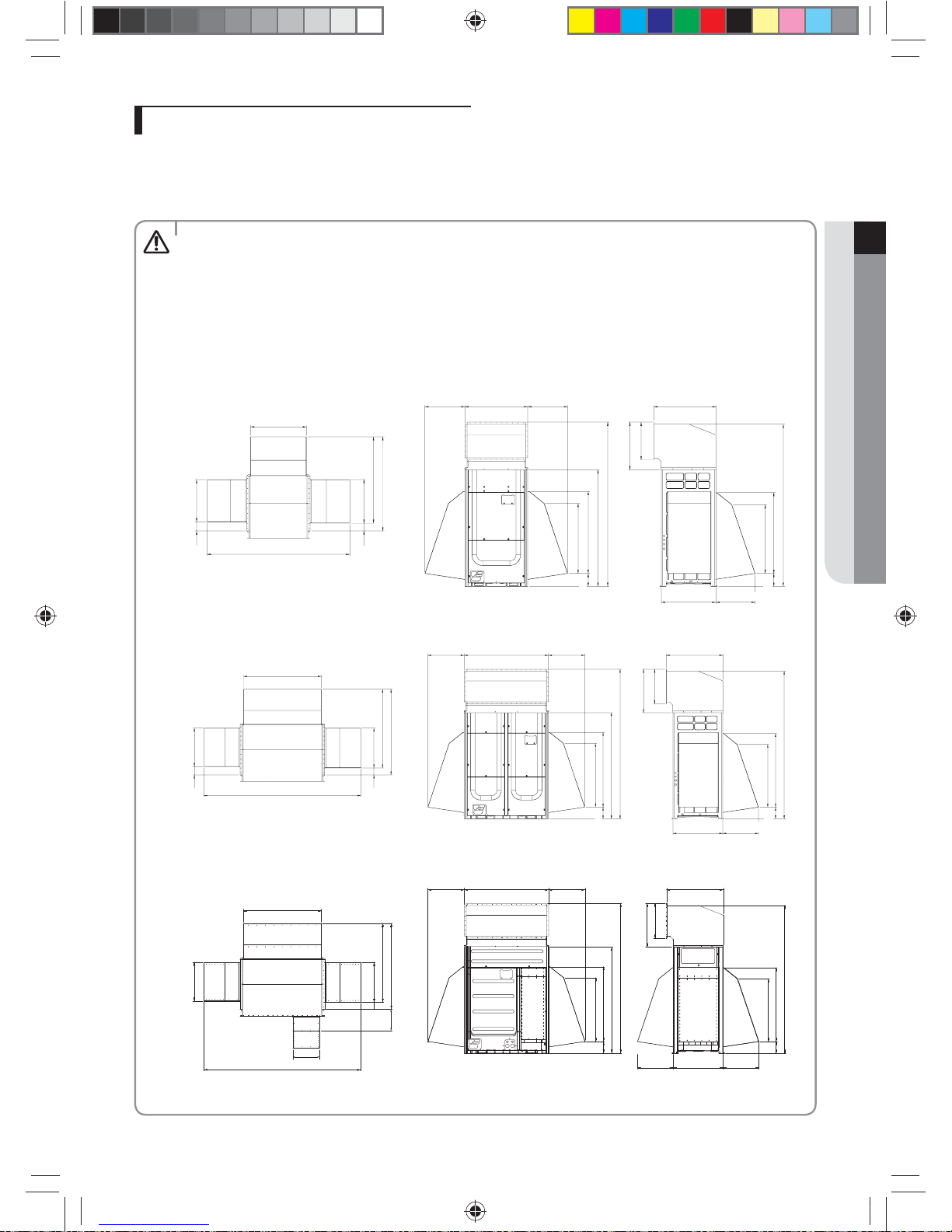
Installing the outdoor unit in windy region
f In windy regions such as near sea shores, protection wall or wind protection duct must be installed for normal operation
of the outdoor unit. (Refer to the illustration of the snow prevention duct, for installing the wind protection duct.)
f Install the wind prevention duct with the consideration of major wind direction. If the direction of the discharge part is
same as major direction of the wind, it could cause product’s performance decrease.
Cautions regarding on installing the frame and selecting the base ground
• The base ground must be solid and the outdoor unit must be xed with anchor bolts.
• Make sure to install outdoor unit in a place strong enough to withstand its weight. If the place cannot withstand
the weight of the outdoor unit, outdoor unit may fall and cause personal injury.
• When installing on a rooftop subject to strong wind, countermeasures must be taken to prevent the unit from
falling down.
• Use a frame that is resistant to corrosion.
782 (30.79)
560 (22.05) 880 (34.05) 560 (22.05)
871 (34.29)
765 ( 30.12)
2300 (90.55)
668 (26.30)
532 (20.94)
2271 (89.41)
1134 (44.65)
965 (37.99)
180 (7.09)
1632 (64.25)
1150 (45.28)
980 (38.58)
180 (7.09)
2000 (78.74)
127 (5) 593 (23.35)
1318 (51.89)
1210 (47.64)
612 (24.09)
108 (4.25)
550 (21.65)
<AM072F✴Series>
Unit: mm (inch)
1197 (47.13)
2415 (95.08)
560 (22.05) 560 (22.05)1295 (50.98)
593 (23. 35)
127 (5)
1318 (51.89)
1210 (47.64)
612 (24.09)
108 (4.25)
2300 (90.55)
1632 (64.25)
1150 (45.28)
980 (38.58)
180 (7.09)
871 (34.29)
765 ( 30.12)
668 (26.30)
532 (20.94)
2271 (89.41)
1134 (44.65)
965 (37.99)
180 (7.09)
550 (21.65)
<AM096/120/144F✴, AM168/192H✴, AM072/096K✴ Series>
<AM216KXVGJ✴>
406
2415
550
180
1080
640
1252
1315
552
1192
560 560 8711295
1255
1732
1080
1255
2371
2400
668
532
180
550 550765
CAUTION
k}tGzG㨰䛙G㐘㞬ὤGptluki]_TWZ_XYhTW_UGGGYZ YWX_TW]TXXGGG㝘䟸G[a[_aY^
24
Refrigerant pipe installation
• When installing, make sure there is no leakage. When collecting the refrigerant, stop the compressor rst before
removing the connection pipe. If the refrigerant pipe is not properly connected and the compressor works
with the service valve open, the pipe inhales the air and it makes the pressure inside of the refrigerant cycle
abnormally high which may lead to explosion and injury.
WARNING
Refrigerant pipe work
f The length of refrigerant pipe should be as short as possible and the height dierence between an indoor and outdoor
unit should be minimized.
f Piping work must be done within allowable piping length, height dierence, and the allowable length after branching.
f The pressure of the R-410A is high. Use only certied refrigerant pipe and follow the installation method.
f After installing the pipes, calculate the total length of the pipe to check if additional refrigerant is needed. When you need
to charge the additional refrigerant, make sure to use R-410A refrigerant.
f Use clean refrigerant pipe and there shouldn’t be any harmful ion, oxide, dust, iron content or moisture inside pipe.
f Use tools and accessories that t on R-410A only.
Tool Installation process/purpose Compatibility with conventional tool
Pipe cutter
Refrigerant pipe
installation
Pipe cutting
Compatible
Flaring tool Pipe aring
Refrigerant
machine oil
Apply refrigerant
oil on ared part
Exclusive ether oil, ester oil, alkali benzene oil or synthetic oil
Torque wrench
Connect are nut
with pipe
Compatible
Pipe bender Pipe bending
Nitrogen gas
Air tightness test
Prevent oxidation
within the pipe
Welder Pipe welding
Manifold gage Air tightness
test ~ additional
refrigerant
charging
Vacuuming,
charging
refrigerant
and checking
operation
Need exclusive one to prevent mixture of R-22 refrigerant oil use and
also the measurement is not available due to high pressure
Refrigerant
charging hose
Need exclusive one since there is risk of refrigerant leakage or inow
of impurities
Vacuum pump Pipe drying
Compatible (Use products which contain the check valve to prevent
the oil from owing backward into the outdoor unit.) Use the one
that can be vacuumed up to -100.7kpa(5Torr).
Scale for
refrigerant
charging
Charging refrigerant Compatible
Gas leak detector Gas leak test
Need exclusive one
(Ones used for R-134a is compatible)
Flare nut
Must use the are nut equipped with the product. Refrigerant leakage may occur when the conventional are
nut for R-22 is used.
k}tGzG㨰䛙G㐘㞬ὤGptluki]_TWZ_XYhTW_UGGGY[ YWX_TW]TXXGGG㝘䟸G[a[_aY^
25
ENGLISH
Selecting refrigerant pipe
First branch joint
Increase the main
pipe size
f Install the refrigerant pipe according to main pipe size of each outdoor unit capacity.
f When the pipe length (including elbow) between an outdoor unit and the farthest indoor unit exceeds 90m (295.28ft),
you must increase the size of the pipe (main pipe) by one grade which connects between the outdoor unit to the rst
branch joint.
f For H/R model, When the pipe length (including elbow) between an outdoor unit and the farthest indoor unit exceeds
90m, you must increase the size of the liquid pipe by one grade among the pipes(main pipe) which connects between
the outdoor unit to the rst branch joint.
k}tGzG㨰䛙G㐘㞬ὤGptluki]_TWZ_XYhTW_UGGGY\ YWX_TW]TXXGGG㝘䟸G[a[_aY^
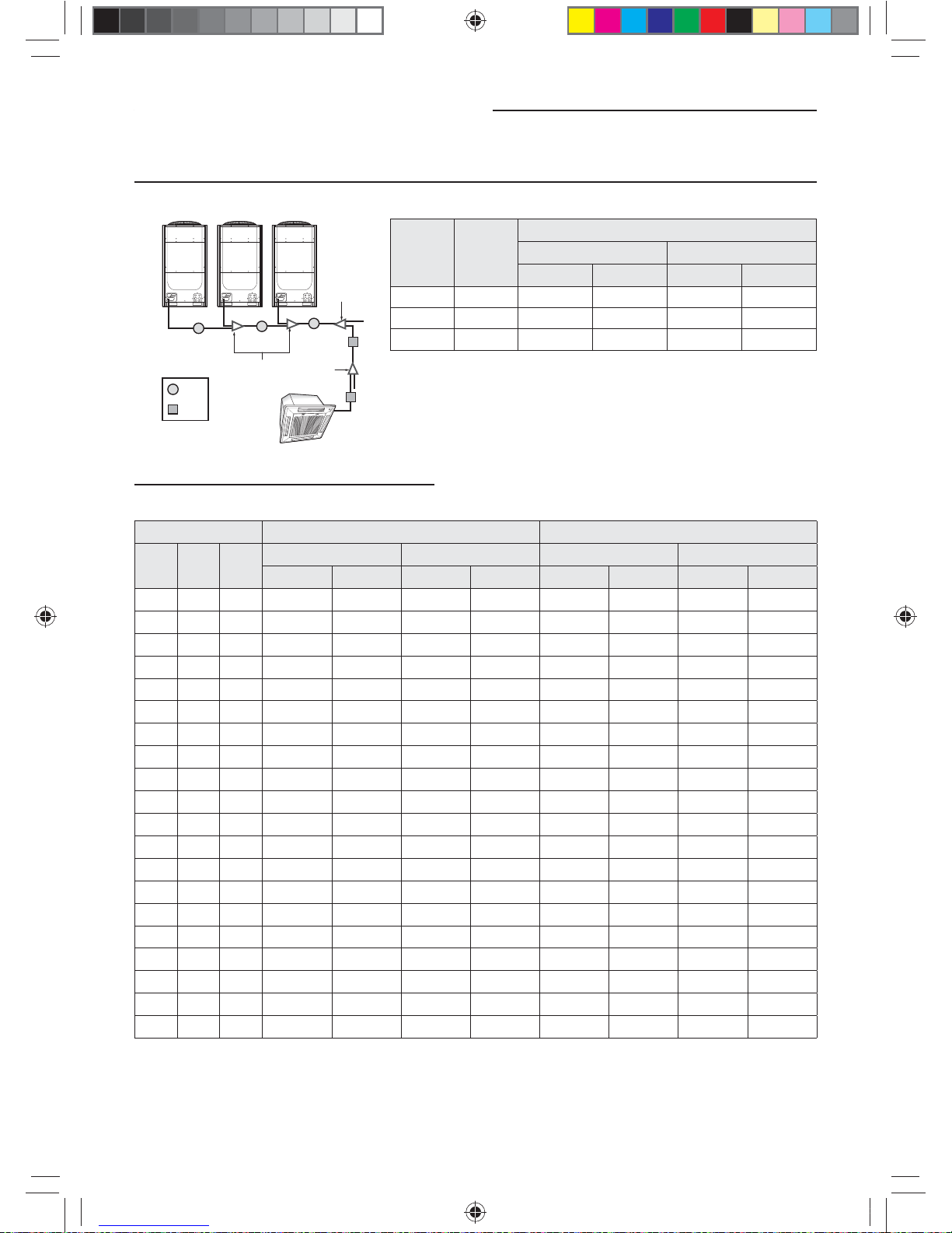
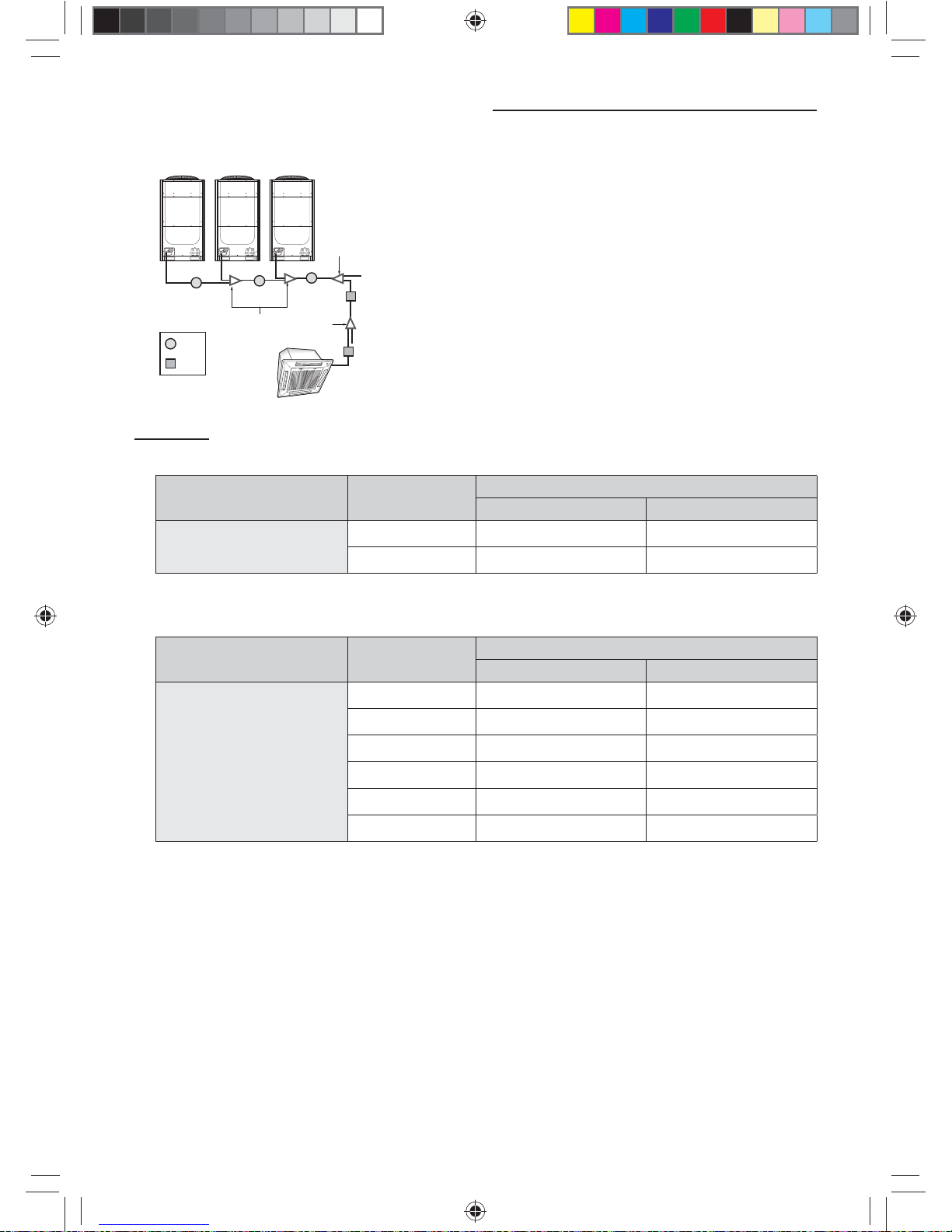
26
Refrigerant pipe installation
H/P
16Ton 12Ton
(D)
(E)(C)
(A)
(B)
(3)(2)(1)
6Ton
Ex.) 34 Ton
Ton No.
Pipe size (O.D)
Liquid pipe Gas pipe
mm inch mm inch
16 (1) 15.88 5/8 28.58 1 1/8
28 (2) 19.05 3/4 34.92 1 3/8
34 (3) 19.05 3/4 41.28 1 5/8
Size of the pipe connected to the outdoor unit (A)
Select the size of the pipe according to the below table.
Outdoor unit capacity Main pipe length within 90m (295.3ft) Size up(Main pipe length over 90m (295.3ft))
Ton MBH KW
Liquid Gas Liquid Gas
mm inch mm inch mm inch mm inch
6 72 21.1 9.52 3/8 19.05 3/4 12.7 1/2 22.22 7/8
8 96 28.1 9.52 3/8 22.22 7/8 12.7 1/2 25.4 1
note1)
10 120 35.2 12.7 1/2 28.58 1 1/8 15.88 5/8 28.58 1 1/8
12 144 42.2 12.7 1/2 28.58 1 1/8 15.88 5/8 31.75 1 1/4
note2)
14 168 49.2 15.88 5/8 28.58 1 1/8 19.05 3/4 31.75 1 1/4
note2)
16 192 56.3 15.88 5/8 28.58 1 1/8 19.05 3/4 31.75 1 1/4
note2)
18 216 63.3 15.88 5/8 28.58 1 1/8 19.05 3/4 31.75 1 1/4
note2)
20 240 70.3 15.88 5/8 28.58 1 1/8 19.05 3/4 31.75 1 1/4
note2)
22 264 77.4 19.05 3/4 34.92 1 3/8 22.22 7/8 38.1 1 1/2
note3)
24 288 84.4 19.05 3/4 34.92 1 3/8 22.22 7/8 38.1 1 1/2
note3)
26 312 91.4 19.05 3/4 34.92 1 3/8 22.22 7/8 38.1 1 1/2
note3)
28 336 98.4 19.05 3/4 34.92 1 3/8 22.22 7/8 38.1 1 1/2
note3)
30 360 105.5 19.05 3/4 41.28 1 5/8 22.22 7/8 41.28 1 5/8
32 384 112.5 19.05 3/4 41.28 1 5/8 22.22 7/8 41.28 1 5/8
34 408 119.5 19.05 3/4 41.28 1 5/8 22.22 7/8 41.28 1 5/8
36 432 126.6 19.05 3/4 41.28 1 5/8 22.22 7/8 41.28 1 5/8
38 456 133.6 19.05 3/4 41.28 1 5/8 22.22 7/8 41.28 1 5/8
40 480 140.7 19.05 3/4 41.28 1 5/8 22.22 7/8 41.28 1 5/8
42 504 147.7 19.05 3/4 41.28 1 5/8 22.22 7/8 41.28 1 5/8
44 528 154.7 19.05 3/4 41.28 1 5/8 22.22 7/8 41.28 1 5/8
Note1) If 1" (25.4mm) pipe is not available on site, use 1 1/8" (28.58mm) pipe.
Note2) If 1 1/4" (31.75mm) pipe is not available on site, use 1 3/8" (34.92mm) pipe.
Note3) If 1 1/2" (38.1mm) pipe is not available on site, use 1 5/8" (41.28mm) pipe.
k}tGzG㨰䛙G㐘㞬ὤGptluki]_TWZ_XYhTW_UGGGY] YWX_TW]TXXGGG㝘䟸G[a[_aY^
27
ENGLISH
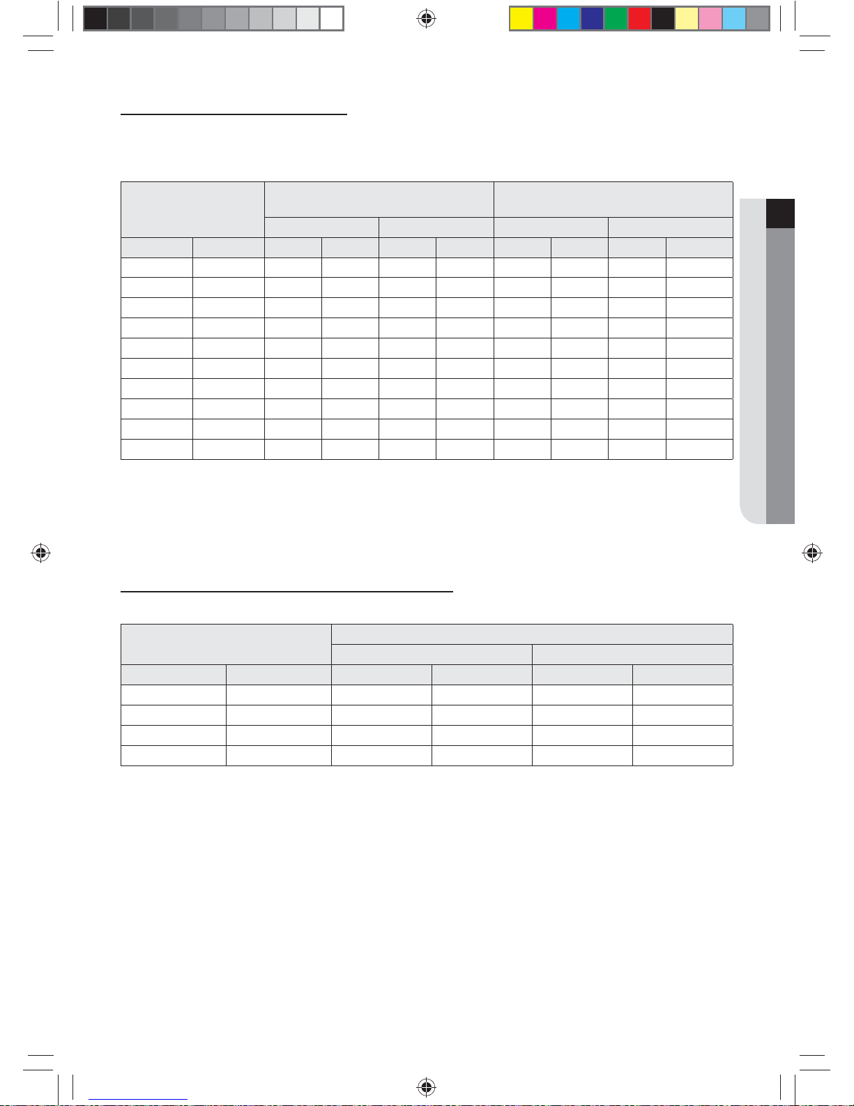
Size of the pipe between branch joints (B)
Select the pipe size according to the sum of indoor unit capacity which will be connected after the branch.
❋ However, if the size of the pipe between branch joints (B) is bigger than the size of the pipe connected to the outdoor
unit (A), apply the pipe size (A).
Indoor unit capacity
Branch pipe length within 45m(147.6ft)
note1)
Branch pipe length between
45~90m(147.6~295.3ft)
note1)
Liquid Gas Liquid Gas
MBH KW mm inch mm inch mm inch mm inch
~51 ~15.0 9.52 3/8 15.88 5/8 12.7 1/2 19.05 3/4
51~76 15.0~22.4 9.52 3/8 19.05 3/4 12.7 1/2 22.22 7/8
76~96 22.4~28.1 9.52 3/8 22.22 7/8 12.7 1/2 25.4 1
note2)
96~136 28.1~40.0 12.7 1/2 28.58 1 1/8 15.88 5/8 28.58 1 1/8
136~154 40.0~45.0 12.7 1/2 28.58 1 1/8 15.88 5/8 31.75 1 1/4
note3)
154~240 45.0~70.3 15.88 5/8 28.58 1 1/8 19.05 3/4 31.75 1 1/4
note3)
240~336 70.3~98.4 19.05 3/4 34.92 1 3/8 22.22 7/8 38.1 1 1/2
note4)
336~461 98.4~135.2 19.05 3/4 41.28 1 5/8 22.22 7/8 41.28 1 5/8
461~577 135.2~169 19.05 3/4 41.28 1 5/8 22.22 7/8 53.98 2 1/8
577 ~ 169.0 ~ 22.22 7/8 53.98 2 1/8 25.40 1
note2)
53.98 2 1/8
Note1) Note on measuring distance between branch joints (B) : You must measure the distance between rst branch joint
to the last indoor unit. (NOT from rst joint to the last branch joint)
Note2) If 1" (25.4mm) pipe is not available on site, use 1 1/8" (28.58mm) pipe.
Note3) If 1 1/4" (31.75mm) pipe is not available on site, use 1 3/8" (34.92mm) pipe.
Note4) If 1 1/2" (38.1mm) pipe is not available on site, use 1 5/8" (41.28mm) pipe.
Size of the pipe between the branch joint and the indoor unit
Make a selection according to outdoor unit capacity.
Indoor unit capacity
Pipe Size(O.D)
Liquid Gas
MBH KW mm inch mm inch
~20 ~6.0 6.35 1/4 12.7 1/2
24~52 7.1~16.0 9.52 3/8 15.88 5/8
68~78 20.0~23.0 9.52 3/8 19.05 3/4
78~96 23.0~29.0 9.52 3/8 22.22 7/8
k}tGzG㨰䛙G㐘㞬ὤGptluki]_TWZ_XYhTW_UGGGY^ YWX_TW]TXXGGG㝘䟸G[a[_aY^
28
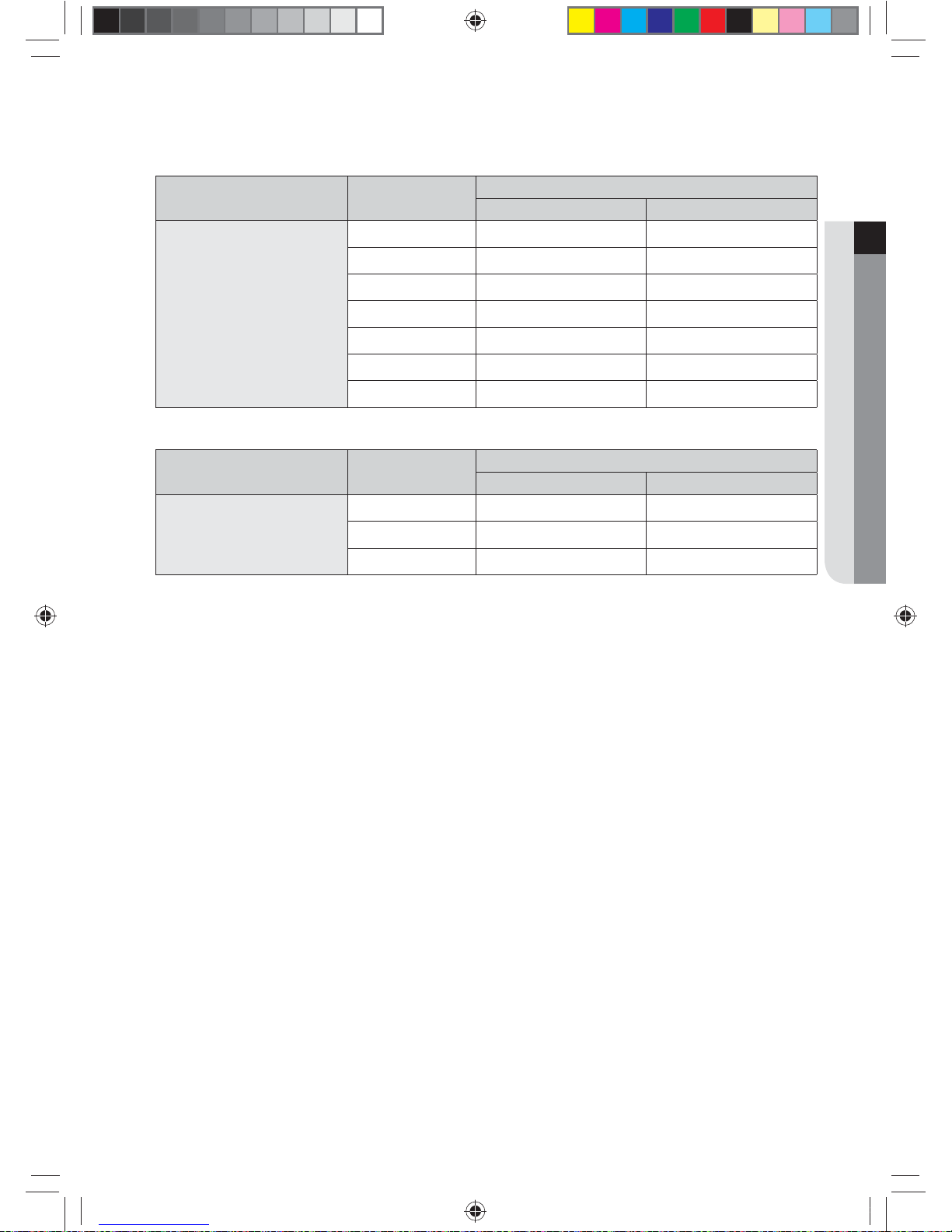
Refrigerant pipe installation
16Ton 12Ton
(D)
(E)(C)
(A)
(B)
(3)(2)(1)
6Ton
Branch joint
f Branch joint between outdoor units (C)
Classication Model name
Specication
MBH kW
Y-joint for outdoor unit (C)
MXJ-TA3819M 461 and below 135.2 and below
MXJ-TA4422M 478 and over 140.2 and over
f First branch joint (D)
Make a selection according to outdoor unit capacity.
Classication Model name
Outdoor unit capacity
MBH kW
Y-joint (D)
MXJ-YA2512M Over 51 ~ 136 and below Over 15.0 ~ 40.0 and below
MXJ-YA2812M Over 136 ~ 154 and below Over 40.0 ~ 45.0 and below
MXJ-YA2815M Over 154 ~ 240 and below Over 45.0 ~ 70.3 and below
MXJ-YA3419M Over 240 ~ 336 and below Over 70.3 ~ 98.4 and below
MXJ-YA4119M Over 336 ~ 461 and below Over 98.4 ~ 135.2 and below
MXJ-YA4422M Over 461 Over 135.2
k}tGzG㨰䛙G㐘㞬ὤGptluki]_TWZ_XYhTW_UGGGY_ YWX_TW]TXXGGG㝘䟸G[a[_aY^
29
ENGLISH
f Branch joint (E)
Select a branch joint according to the sum of indoor unit capacity which will be connected after the branch.
1) Y-joint
Classication Model name
Specication
MBH kW
Y-joint (E)
MXJ-YA1509M 51 and below 15.0 and below
MXJ-YA2512M Over 51 ~ 136 and below Over 15.0 ~ 40.0 and below
MXJ-YA2812M Over 136 ~ 154 and below Over 40.0 ~ 45.0 and below
MXJ-YA2815M Over 154 ~ 240 and below Over 45.0 ~ 70.3 and below
MXJ-YA3419M Over 240 ~ 336 and below Over 70.3 ~ 98.4 and below
MXJ-YA4119M Over 336 ~ 461 and below Over 98.4 ~ 135.2 and below
MXJ-YA4422M Over 461 Over 135.2
2) Distribution header
Classication Model name
Specication
MBH kW
Distribution header (E)
MXJ-HA2512M 154 and below (for 4 rooms) 45.0 and below (for 4 rooms)
MXJ-HA3115M 240 and below (for 8 rooms) 70.3 and below (for 8 rooms)
MXJ-HA3819M Over 240 (for 8 rooms) Over 70.3 (for 8 rooms)
k}tGzG㨰䛙G㐘㞬ὤGptluki]_TWZ_XYhTW_UGGGY` YWX_TW]TXXGGG㝘䟸G[a[_aY^
30
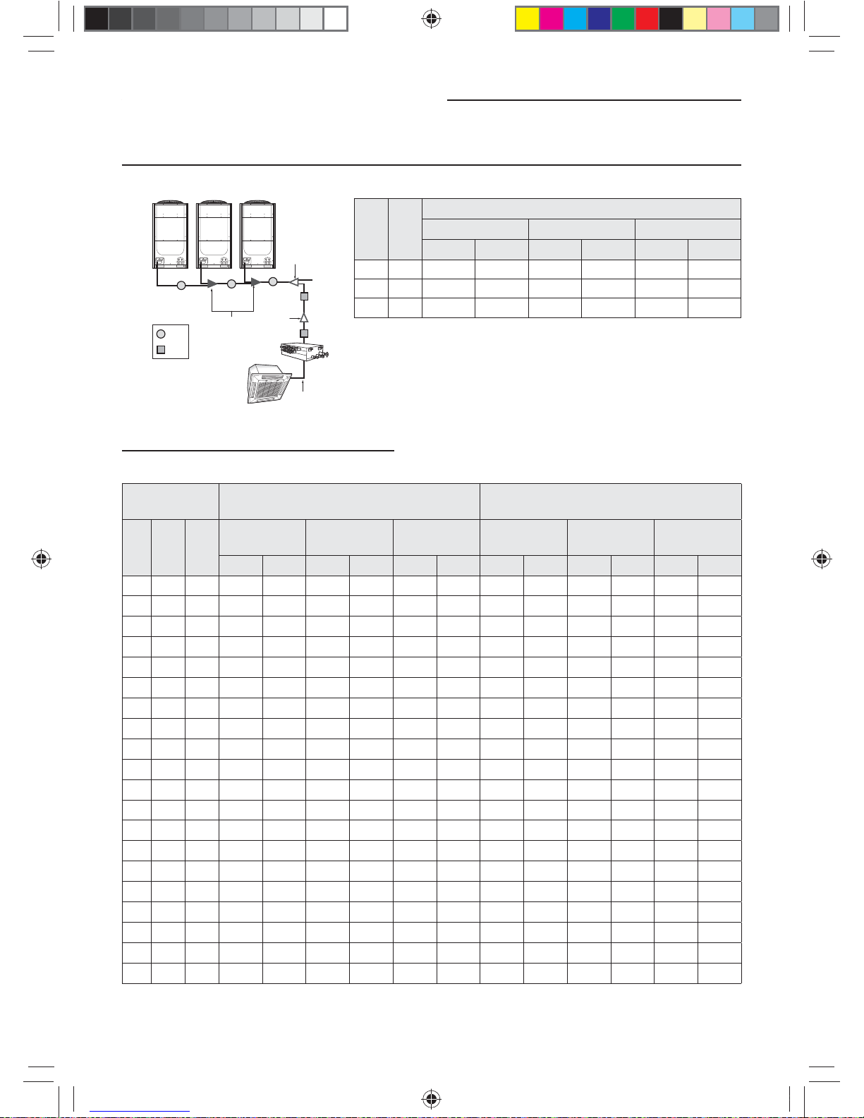
Refrigerant pipe installation
H/R
(A)
(B)
16Ton 12Ton
(D)
(E)
(F)
(C)
(3)
(2)
(1)
6Ton
Ex.) 34 Ton
Ton N o.
Pipe size (O.D)
Liquid Gas High pressure Gas
mm inch mm inch mm inch
10 (1) 15.88 5/8 28.58 1 1/8 28.58 1 1/8
28 (2) 19.05 3/4 34.92 1 3/8 28.58 1 1/8
34 (3) 19.05 3/4 41.28 1 5/8 34.92 1 3/8
Size of the pipe connected to the outdoor unit (A)
Select the size of the pipe according to the below table.
Outdoor unit
capacity
Main pipe length within 90m (295.3ft) Size up(Main pipe length over 90m (295.3ft))
Ton MBH KW
Liquid Gas
High pressure
Gas
Liquid Gas
High pressure
Gas
mm inch mm inch mm inch mm inch mm inch mm inch
6 72 21.1 9.52 3/8 19.05 3/4 15.88 5/8 12.7 1/2 19.05 3/4 15.88 5/8
8 96 28.1 9.52 3/8 22.22 7/8 19.05 3/4 12.7 1/2 22.22 7/8 19.05 3/4
10 120 35.2 12.7 1/2 28.58 1 1/8 22.22 7/8 15.88 5/8 28.58 1 1/8 22.22 7/8
12 144 42.2 12.7 1/2 28.58 1 1/8 22.22 7/8 15.88 5/8 28.58 1 1/8 22.22 7/8
14 168 49.2 15.88 5/8 28.58 1 1/8 22.22 7/8 19.05 3/4 28.58 1 1/8 22.22 7/8
16 192 56.3 15.88 5/8 28.58 1 1/8 28.58 1 1/8 19.05 3/4 28.58 1 1/8 28.58 1 1/8
18 216 63.3 15.88 5/8 28.58 1 1/8 28.58 1 1/8 19.05 3/4 28.58 1 1/8 28.58 1 1/8
20 240 70.3 15.88 5/8 28.58 1 1/8 28.58 1 1/8 19.05 3/4 28.58 1 1/8 28.58 1 1/8
22 264 77.4 19.05 3/4 34.92 1 3/8 28.58 1 1/8 22.22 7/8 34.92 1 3/8 28.58 1 1/8
24 288 84.4 19.05 3/4 34.92 1 3/8 28.58 1 1/8 22.22 7/8 34.92 1 3/8 28.58 1 1/8
26 312 91.4 19.05 3/4 34.92 1 3/8 28.58 1 1/8 22.22 7/8 34.92 1 3/8 28.58 1 1/8
28 336 98.4 19.05 3/4 34.92 1 3/8 28.58 1 1/8 22.22 7/8 34.92 1 3/8 28.58 1 1/8
30 360 105.5 19.05 3/4 41.28 1 5/8 34.92 1 3/8 22.22 7/8 41.28 1 5/8 34.92 1 3/8
32 384 112.5 19.05 3/4 41.28 1 5/8 34.92 1 3/8 22.22 7/8 41.28 1 5/8 34.92 1 3/8
34 408 119.5 19.05 3/4 41.28 1 5/8 34.92 1 3/8 22.22 7/8 41.28 1 5/8 34.92 1 3/8
36 432 126.6 19.05 3/4 41.28 1 5/8 34.92 1 3/8 22.22 7/8 41.28 1 5/8 34.92 1 3/8
38 456 133.6 19.05 3/4 41.28 1 5/8 34.92 1 3/8 22.22 7/8 41.28 1 5/8 34.92 1 3/8
40 480 140.7 19.05 3/4 41.28 1 5/8 34.92 1 3/8 22.22 7/8 41.28 1 5/8 34.92 1 3/8
42 504 147.7 19.05 3/4 41.28 1 5/8 34.92 1 3/8 22.22 7/8 41.28 1 5/8 34.92 1 3/8
44 528 154.7 19.05 3/4 41.28 1 5/8 34.92 1 3/8 22.22 7/8 41.28 1 5/8 34.92 1 3/8
❋ For HR model, only increase the size of the liquid pipe If pipe length exceeds 90m
k}tGzG㨰䛙G㐘㞬ὤGptluki]_TWZ_XYhTW_UGGGZW YWX_TW]TXXGGG㝘䟸G[a[_aY_
 Loading...