

Page 1
5. Troubleshooting
5-1 Items to be checked first
1 ) Is the voltage of the power corre c t ?
The input voltage shall be rating voltage ±10% range.
The airconditioner may not operate properly if the voltage is out of this range.
2 ) Is the link cable linking the indoor unit and the outdoor unit linked pro p e r l y ?
The indoor unit and the outdoor unit shall be linked by 5 cables.
Check the terminals if the indoor unit and outdoor unit are properly linked by the same number of cables.
Otherwise the airconditioner may not operate pro p e r l y.
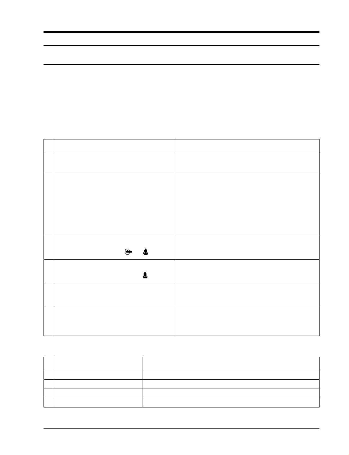
3 ) When a problem occurs due to the contents illustrated in the table below it is a symptom not related to the
malfunction of the airc o n d i t i o n e r.
NO Operation of air conditioner
1 The COOL operation indication LED (Green) blinks when a
power plug of the indoor unit is plugged in for the first time.
2 In a COOL operation mode, the compressor does not
operate at a room temperature higher than the setting
temperature that the IN DOOR FAN should operate.
In a HEAT operation mode, the compressor does not
operate at a room temperature lower than the setting
temperature that indoor fan should
operate.
3 Fan speed setting is not allowed in AUTO or DRY mode.
4 Compressor stops operation intermittently in DRY mode.
5 Timer LED only of the indoor unit lights up and the
air conditioner does not operate.
Explanation
It indicates power is on. The LED stops blinking if the operation
ON/OFF button on the remote control unit is pushed.
In happens after a delay of 3 minutes when the compressor is reoperated. The same phenomenon occurs when a power is on.
As a phenomenon that the compressor is reoperated after a delay of
3 minutes, the indoor fan is adjusted automatically with reference
to a temperature of the air blew
The speed of the indoor fan is set to LL in DRY mode.
Fan speed is 5 steps is selected automatically in AUTO mode.
Compressor operation is controlled automatically in DRY mode
depending on the room temperature and humidity.
Timer is being activated and the unit is in ready mode.
The unit operates normally if the timer operation is cancelled.
6 The compressor stops intermittently in a COOL mode or DRY
mode, and fan speed of the indoor unit decreases.
The compressor stops intermittently or the fan speed of the indoor unit
decreases to prevent inside/outside air frozen depending on the
inside/outside air temperature.
4 ) Indoor unit observes operation condition of the air conditioner, and displays self diagnosis details
on the display panel.
NO Display
1 Operating LED blinking (1Hz)
2 TIMER LED blinking (1Hz)
3 O P E R ATING and TIMER LED blinking (1Hz)
4 FAN LEA blinking (1Hz)
Samsung Electronics
Restore from power failure (input initial power)
Indoor unit Room sensor Error (open or short)
Indoor unit heat exchanger temperature sensor Error (open or short)
Indoor fan malfunctioning (for spead is Below 38Orpm)
Self Diagnosis
5-1
Page 2
5-2 Fault Diagnosis by Symptom
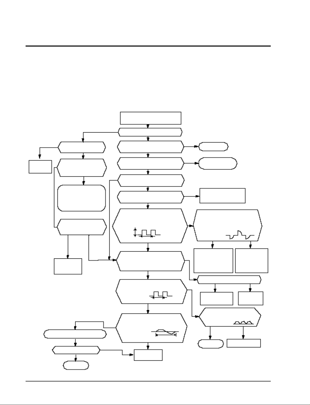
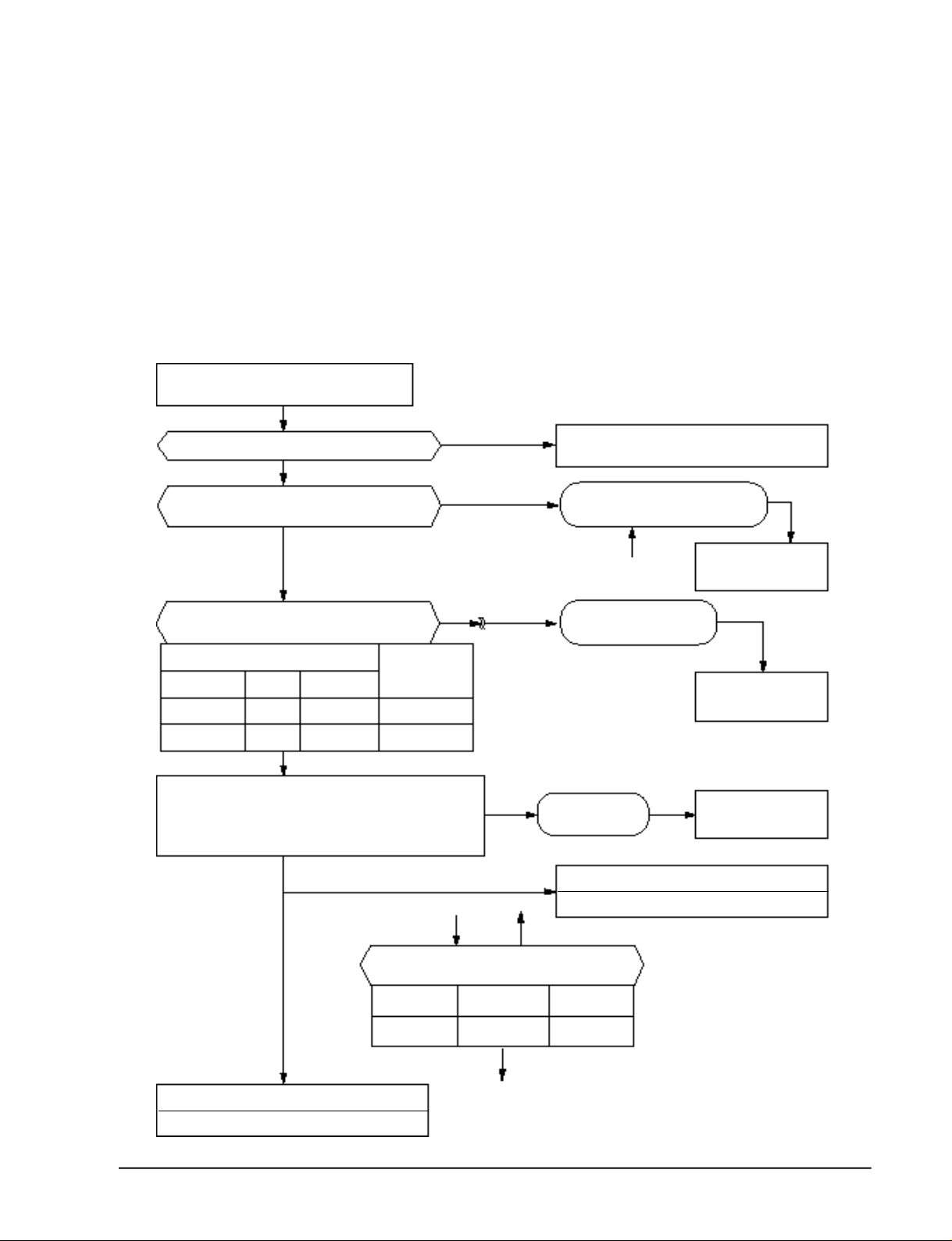
5-2-1 No Power (completely dead)-Initial diagnosis
1) Checklist :
(1) Is input voltage normal?
(2) Is AC power linked corre c t l y ?
(3) Are connections between primary side, secondary side of the power transformer and PCB good.
(4) Is output voltage of DC regulator IC KA7812 (IC01) normal? (11 V D C - 1 2 . 5 V D C )
(5) Is output voltage of DC regulator IC KA7805 (IC02) normal? (4.5VDC-5.5VDC)
2 ) Troubleshooting pro c e d u re
NO
YES
Replace PCB
display
Is DC voltage of PCB
display normal?
NO
Is 198~264VAC
applied to the
primary side of the power
transformer?
NO
•Check linkage between
power cord and
terminal tap
•Check fuse
Is 14~18VAC appear in
the secondary side of the
power transformer?
YESNO
Replace power
transformer
Replace resonator (X501)
Is operation normal?
YES
OK
Remove power cord and plug in again
in approx. 5 seconds
Is operation lamp blinking?
Does operation start when
run/stop button on the remote
controller unit pushed?
Is transmission display of the remote
controller unit blinking?
Is "beep"sound heard from the main
NO
Is DC voltage of the PCB module
Are voltages of #62 (compressor),
#60(4 way valve) and #61 (outdoor fan)
of the micom normal? 5VDC
Is voltage of #63 (indoor fan) of the
DC5V
Is voltage at #32 terminal of the Micom normal?
Is voltage at #64 terminal of the Micom normal?
Is voltage at #25 terminal of the micom
Are voltage at #30 and #31 of the
NO
NO
YES
NO
YES
unit?
YES
normal?
YES
micom normal?
10ms
NO
YES
normal?
10ms
YES
micom normal?
100ns
YES
Replace
micom
0VDC
5VDC
YES
NO
NO
YES
NO
NO
Normal
Refer to remote control
unit fault diagnosis
Replace PCB
module.
Are voltages at RY71(Compressor)
RY73(4-way valve) and SY72(outdoor fan)
normal? DC12V
Is voltage at SS71(indoor fan)
YES
Check connections
compressor 4-way
valve, outdoor fan and
indoor fan.
Is output voltage of ICO2 normal?
YES
Check PCB pattern.
Replace main PCB.
Is voltage output terminal of
D101~D105(IN4007) normal?
YES
OK
NO
Replace
RY71, RY73,
RY72 and
SS71
NO
Replace ICO2
NO
Replace IN4007
5-2
Samsung Electronics
Page 3
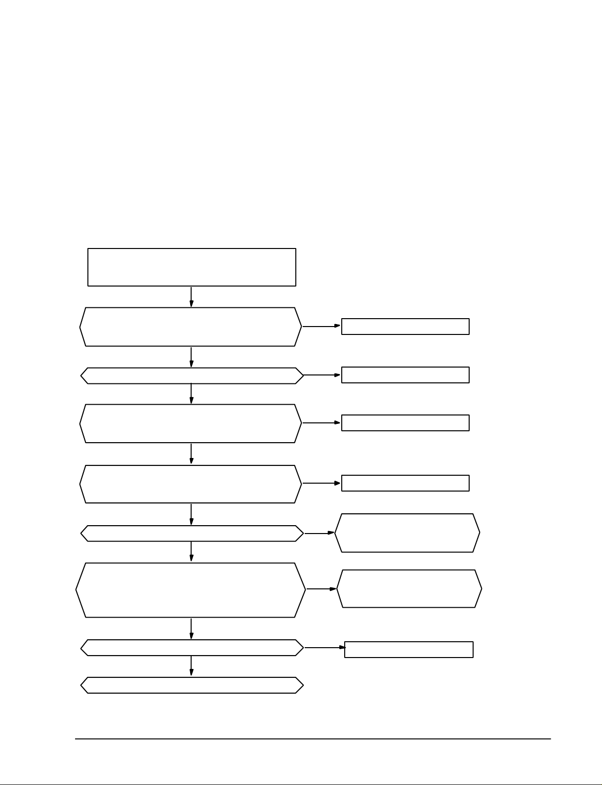
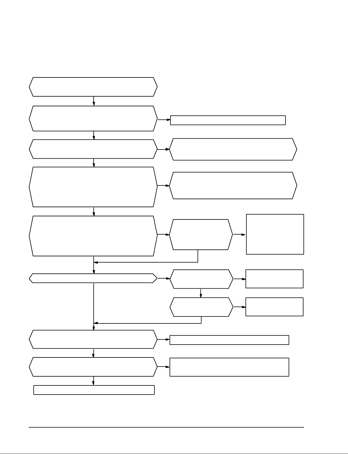
5-2-2 When the power is not applied(Outdoor unit)
1) Checking points
(1) Is the voltage of the power normal?
(2) Is the power line in good contact?
(3) A re the primary (CN71) and secondary (CN11) connectors of the power trans in good
c o n t a c t ?
(4) Is the power voltage of the IC01 (KA7812) normal? (DC11 . 5 V ~ D C 1 2 . 5 V )
2 ) Trouble shooting pro c e d u re
Turn off the power, and then turn on the power
in five minutes.
Y
Troubleshooting
Does the power of the IC01(KA7812) match with
the voltage of DC12V?
Y
Is the F701(3.15A) fuse blown?
Y
Is the secondary voltage of the trans normal?
(AC15V~AC25V)
Y
Is the first voltage of the trans normal?
(AC198V~AC264V)
Y
Is the rectifying diode(D101~D104) normal?
Y
Is the voltage at both ends of the C102
electrolytic condenser in the range of DC16~DC25V?
Is the voltage at both ends of the C104 electrolytic
condenser DC12V?
N
N
N
N
N
N
Normal operation
Replace the fuse
Replace the trans
Replace the trans
Check and replace
the rectifying diode
Replace the C102
and C104.
Is the IC01(KA7812) normal?
Samsung Electronics
Y
N
Replace the IC01
Y
End
5-3
Page 4
Troubleshooting
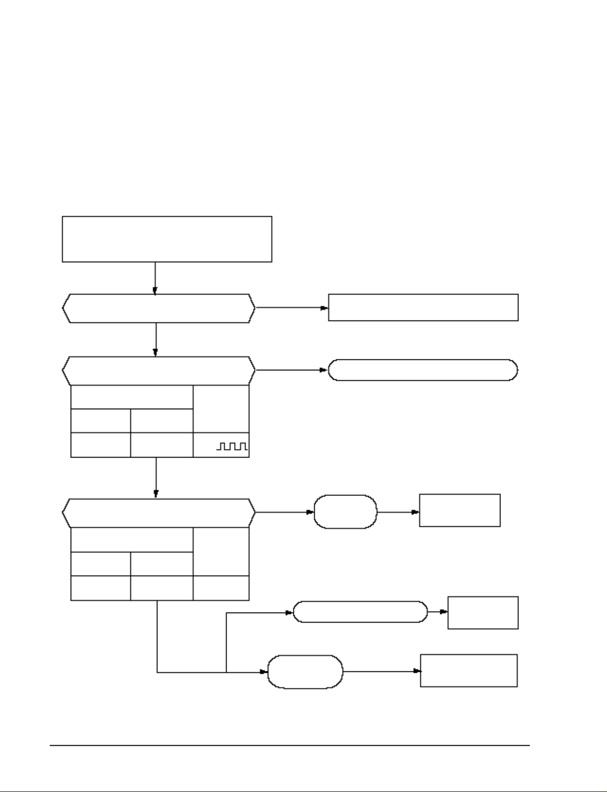
5-2-3 When the Indoor Unit Fan Does Not Operate. (Initial Diagnosis)
1) Checklist :
(1) Is the indoor unit fan motor properly connected with the connector (CN73)?
(2) Is the AC voltage corre c t ?
(3) Is HALL IC in indoor fan motor properly connected with the connector (CN43)?
(4) Is the running capacitor properly connected with the terminal?
2 ) Troubleshooting pro c e d u re
After unplugging out the power cord should
be reconnected within five seconds.
YES
Does the operating lamp(Green) blink?
YES
Does the Solid State Relay(SS71) work
properly?
Test rod location
+
SS71- SS71- 12V
Is the supply voltage of the fan
Test rod location
PCB CN73
-
YES
motor sufficient?
Condition
Fan operate AC 180V
Normal
Voltage
Normal
voltage
NO
NO
NO
Check as in the procedur “NO power parts”
Refer tp page 5-2.
Microcomputer is out of order.
PCB is
out of order.
PCB should
be replaced.
5-4
YES
Fan motor
is out of order.
MF-C is out of order
Replace MFC
Fan motor
should be replaced.
Samsung Electronics
Page 5
5-2-4 When the Outdoor Unit Does Not Operate. (Initial Diagnosis)
1 ) Checklist :
(1) Is input voltage normal?
(2) Is the set temperature of the remote control higher than room temperature in COOL m o d e ?
(3) Is the POWER IN connector (terminal-tab) linked corre c t l y ?
(4) Is the outdoor unit properly connected with the TERMINAL BLOCK connector(5P)?
2 ) Troubleshooting pro c e d u re
(1) Checking pro c e d u res for the indoor unit.
After unplugging out the power cord should be
reconnected within five seconds.
Troubleshooting
Does the operating lamp blink
YES
Does the timer lamp blink during operation ?
NO
Is the power relay RY71 operated by adjusting the
room temperature?
Test rod location Normal
+ - Condition Voltage
IC1 Pin No.63 GND RY73 ON DC 4.8V
IC1 Pin No.62 GND RY72 ON DC 4.8V
NO
1) Is AC 198 - 264V applied relay between Terminal Tap(TB71)
and RY 71 terminal No. 3
2) Is AC 198 - 264V applied relay between Terminal Tap(TB71)
andCN 71 terminal No. 1
YES
NO
YES
NO 1
1 NO
YES 3
Check as in the procedure "No Power parts"
Refer to page 5-2.
Room temperature sensor is
out of order
2
Microcomputer is
out of order.
Power relay is
out of order
A Room operation
“A”Compreessor or outdoor fan-motor replaced
2 NO
PCB should be checked.
Power relay should be
PCB should be
checked.
replaced.
B Room or C Room operating
Proceed to the checking points for the outdoor unit.
Samsung Electronics
Is the room sensor normal register?
10°C 20°C 30°C
17.96k Ω 12.09k Ω 8.3k Ω
YES 3
5-5
Page 6
Troubleshooting
(2) Pro c e d u res for checking the outdoor unit.
Turn off the power, and then turn on the
power in 5 seconds.
Y
Does the compressor operate in 2 minutes after
the relay (RY71)
is activated at the indoor unit after 3 minutes?
Y
Does the photo coupler (IC02, IC03)
corresponding to the indoor units (B & C) operate?
Y
Is the DC voltage applied to both ends of the C901?
(1) Is the voltage DC6V when either of the indoor
units (B & C) is turned on?
(2) Is the voltage DC8V when both of the indoor
units are turned on?
Y
(1) Does the N01 pin output of the IC04 maintain "Low"?
(2) Does the N014 pin output of the IC04 maintain "High"?
When either of the indoor units (B & C) is turned on.
(3) Does the N014 pin output of the IC04 maintain "Low"?
When both of the indoor units (B & C) is turned on.
Y
Does the No7 pin output of the IC04 maintain "Low"?
Y
N
N
N
N N
N
•Check and replace the resistance
•Check and replace the electrolytic condenser (C901)
(1) Is the NO3 pin voltage
of the IC04 DC5V?
(2) Is the NO12 pin voltage
of the IC04 DC7V?
Is the No.5 pin voltage
of the IC04 DC5V?
Check and replace the relevant
(R901, R928, R931) and diode (D907, D908).
Y
Normal
IC (IC02, IC03).
• Check and replace the
IC04.
•Check and replace the
resistance.
(R902, R903,R905, R906)
N
Check and replace the
R913, R915 and IC04.
Are the Q901, and 904 in "Turn-off" condition?
Are the Q902, Q903 and Q905 in "Turn-on" condition?
Y
Does the operation of the Q701 lead to
activation of the compressor relay (RY71)?
Y
Replace the "B" compressor.
5-6
Is the voltage at both
ends of the C903 DC10V?
N
N
(Resistance at both ends of the relay: About 150 )
N
Y
Check and replace each transistor
Check and replace the Q701 and relay.
Check and replace the
R911, D901, and C903.
Samsung Electronics
Page 7

5-2-5 When the UP/DOWN Louver Moter Does Not Operate. (Initial Diagnosis)
1) Checklist :
(1) Is input voltage normal?
(2) Is the UP/DOWN louver motor properly connected with the connector (CN61)?
2 ) Troubleshooting pro c e d u re
Remove power cord and plug in again in approx. 5 seconds.
Troubleshooting
Is operating lamp blinking?
Y
Does operation start when swing button of the remote con-
trol unit pushed?
N
Voltage at pin #33-#36 of micom (ICO4)
change?(Squarewave)
Y
Volatge at pin #10, #11, #12, #13 of IC05 (KID65003)
change?(Squarewave)
Y
UP/DOWN louver motor is faulty.
Y
Y
N
N
Check as in the procedure "No Power
parts". Refer to page 5-2.
Normal
Micom (IC04) is faulty.
Driver IC05 (KID65003) is faulty.
Samsung Electronics
5-7
Page 8

Troubleshooting
5-2-6 If Operation By Remote Control Unit Is Impossible. (Initial Diagnosis)
1) Troubleshooting pro c e d u re
Remove power cord and plug in again approx. 5 Seconds
Is operation lamp blinking?
Y
“ “ sound heard from the indoor unit when
ON/OFF button on the remote control unit pushed?
Voltage of battery less than 2.5V (Remote Control Unit)?
LCD display status of REMOCON normal?
Transmission display lamp ( ) blinking when
ON/OFF button on the remote control unit pushed?
Voltage at PIN #30 of Remocon Micom change?
Voltage at collecter of Q601 or Q602 change?
Y
N
Check as in the procedure “NO Power
parts”. Refer to page 5-2.
Y
Y
N
N
N
N
Normal
Replace battery.
LCD is faulty.
Replace button.
Micom is faulty.
Q601(C4375Y) or Q602(C1623Y) is faulty.
IR LED(CL-1L5EU) is faulty.
5-8
Voltage at pin #26 of micom (IC04) change (INDOOR UNIT)?
Y
Micom (IC04) is faulty.
N
Receiver module is faulty.
Samsung Electronics
Page 9

5-2-7 When the SV-BY is Malfunctioning (Outdoor Unit)
1) Checking points
(1) Is the SV1 under normal operating condition?
(2) Is the voltage of the power normal?
(3) Is the connector (CN76) of the SV- B Y in good contact?
(4) Is the resistance at both ends of the solenoid about 1.4kΩ ?
2) Checking pro c e d u re s
(1) When either of the indoor units (B & C) is turned on
Turn off the outdoor power, and then turn
on the power in 5 seconds.
Y
Troubleshooting
Does the SV-BY operate when either of the
indoor units is turned on?
N
Is the voltage of DC6V applied to both ends
of the C901?
Y
(1) Does the No14 pin output of the IC04
maintain "High"?
(2) Does the No1 pin output of the IC04
maintain "Low"?
Y
Are the Q906, and Q907 in "turn-on" condition?
Is the Q908 in "turn-off" condition?
Y
Is the No8 pin output of the IC04 in "High"
condition?
Y
Y
N
(1) Is the No12 pin voltage
N N
N
N
of the IC04 DC7V?
(2) Is the No3 pin voltage
of the IC04 DC5V?
Check and replace each transistor
Is the No10 pin voltage
of the IC04 DC7V?
Normal
• Check and replace the relevant IC (IC02, IC03).
• Check and replace the resistance (R901, R928, R931),
and diode (D907, D908).
Y
N
Y
• Check and replace the IC04.
• Check and replace the
resistance
(R902, R903, R905, R906).
• Check and replace the IC04.
• Check and replace the
resistance (R922, R924).
Does the operation of the Q702 lead to
activation of the SV-BY relay (RY72)?
Replace the SV-BY
Samsung Electronics
N
Y
Check and replace the Q702 and relay.
(Resistance at both ends of the relay: 400Ω )
5-9
Page 10

Troubleshooting
(2) When all of the indoor units (B & C) are turned off
Turn off the outdoor power, and then turn on
the power in 5 seconds.
Y
Is the SV1 turned off after operating for
about 2 minutes
when all of the indoor units (B & C)
are turned off?
N
(1) Does the No14 pin output of
the IC04 maintain "High"?
(2) Does the No1 pin output of "Low"?
Y
Are the Q906 and Q908 in "turn-on"
condition?
Is the Q907 in "turn-off" condition?
Y
Is the No8 pin output of
the IC04 in "High" condition?
Y
The "High" condition should be maintained for about 2 minutes
until the voltage of about DC7V or higher is applied to the C904.
Y
N N
(1) Is the No.12 pin voltage
of the IC04 DC7V?
Normal
(2) Is the No.3 pin voltage
of the IC04 DC5V?
Y
Is the voltage at both
ends of the C901 0V?
Y
N
Check and replace each transistor
N
Is the No10 pin voltage
of the IC04 DC7V?
Y
• Check and replace the IC04.
• Check and replace the IC04
maintain resistance
(R902, R903,R905, R906).
• Check and replace the
N
IC02-IC03.
• Check and replace the C901.
• Check and replace the IC04.
N
• Check and replace the R922,
and R924.
5-10
Is the voltage charged to
the C904 above DC7V?
Y
Does the No8 pin output of
the IC04 change from "High" to "Low"?
The output is changed from "High" to "Low" when charging
Y
Does the turning on and then
turning off of the Q702 lead to
turning off of the SV-BY relay (RY72)?
Y
Replace the SV-BY solenoid.
N
N
Check and replace the R920 and R921.
to the C904 is completed.
N
Check and replace the Q702 and relay.
(Resistance at both ends of the relay: 400Ω)
Check and replace the C904.
IC04 Check and replace
Samsung Electronics
Page 11

5-2-8 When the SV-B is malfunctioning
1) Checking points
(1) Is the SV-B under normal operating condition?
(2) Is the voltage of the power normal?
(3) Is the SV-B connector (CN75) in good contact?
(4) Is the resistance at both ends of the solenoid about 1.4kΩ?
2) Checking pro c e d u re s
Turn off the outdoor power, and then turn it on after 5
seconds
Y
Troubleshooting
Does the SVA operate when the room B among the indoor
unit room B and room C is turned on?
N
Does the photo-coupler (IC02) for the room B among the
indoor unit room B and room C operate?
Y
Is the voltage of about DC5V or above applied to
both ends of the C905?
Y
Is the voltage of about DC6V or above applied to
both ends of the C901?
Y
1 Is the 14th pin output of the IC04 maintained at
"High" level?
2 Is the Ist pin output of the IC04 maintained at
"Low" level?
Y
Y
N
N
N
1 Is the voltage of the 12th pin
N
2 Is the voltage of the 3rd pin
Normal operation
Check and replace the photo coupler (IC02)
•Check and replace the R929, and R930
•Check and replace the C905
•Check and replace the R901, R928 and D908
•Check and replace the C901
for the IC04 about DC7V?
of the IC04 about DC5V?
N
•Check and
replace the IC04
N
•Check and
replace the
resistance(R902,
R903,R905,R906)
Y
Are the Q906, Q907, and Q909 under turn on condition,
and is the Q908 under "turn off" condition?
Y
Is the Q703 turned. on, indicating the
operating of the SV-B relay (RY73)?
Y
Replace the SV-B solenoid valve
Samsung Electronics
N
N
Check and replace the relevant transistor
Check and replace the D905, D909, and Q703 relay
(Coil resistance at both ends of the relay:about 400Ω)
5-11
Page 12

Troubleshooting
5-2-9 When the SV-C is malfunctioning
1) Checking point
(1) Is the SV-C under normal operating condition?
(2) Is the voltage of the power normal?
(3) Is the SV-C connector (CN74) in good contact?
(4) Is the resistance at both ends of the solenoid about 1.4kΩ?
2) Checking pro c e d u re s
Turn off the outdoor power, and then turn it on after 5
seconds
Y
Does the SVB operate when the room C among the indoor
unit room B and room C is turned on?
N
Does the photo-coupier (IC03) for the room C among the
indoor unit rooms B and room C operate?
Y
Is the voltage of about DC5V or above applied to both ends
of the C906?
Y
Is the voltage of about DC6V or above applied to both ends
of the C901?
Y
1 Is the output of the 14th pin of the IC04
maintained a "Hight" level?
2 Is the output of the lst pin of the I04 maintained
at "Low" level?
Y
Y
N
N
N
N
Normal operation
Check and replace the photo coupler(IC03)
•Check and replace the R932, and R933
•Check and replace the C906
•Check and replace the R901, R931, and D907
•Check and replace the C901
1 Is the voltage of the 12th pin
of the IC04 about DC7V?
2 Is the voltage of the 3rd pin
of the IC04 about DC5V?
•Check the
IC04
•Check and
N
replace the
resistance
(R902, R903,
R905, R906)
Y
Are the Q906, Q907 and Q909 turned on with the Q908
being turned off?
Y
Is the Q704 turned on, indicating the operating condition
of the SV-C relay (RY74)?
Y
Replace the SV-C solenoid valve
5-12
N
N
Check and replace the relevant transistor
Check and replace the D906, D910, and Q704 relay
(Coil resistance at both ends of the relay : about 400Ω)
Samsung Electronics
Page 13

N
N
N
Y
Y
Y
N
N N
Y
N
N
Y
Y
Y
Y
N
Y
N
Y
N
Y
Y
5-2-10 When the SV-B and SV-C are malfunctioning with all of the indoor units
(B & C) turned off
1) Checking points
(1) A re the SVA and SVB under normal operating condition?
(2) Is the voltage of the power normal?
(3) A re the SV-B (CN75) and SV-C (CN74) connectors in good contact?
(4) Is the resistance at both ends of the solenoid about 1.4kΩ?
2) Checking pro c e d u re s
Turn off the outdoor power, and then
turn on the power in 5 seconds.
Are the SVA and SVB operate turned off after
operating for about 2 minutes when all
of the indoor units (B & C) are turned off?
Normal
Troubleshooting
(1) Does the No14 pin output of the IC04
maintain "High"?
(2) Does the No1 pin output of the IC04
maintain "High"?
Are the Q906 and Q908 in "turn-on" condition?
Are the Q907 and Q909 in "turn-off" condition?
Is the No8 pin output of
the IC04 in "High" condition?
Do the SVA and SVB operated
The "High" condition should be maintained for about 2 minutes until a voltage
of above DC7V is charged to the C904.
when the Q703, and Q704 are turned on?
Is the voltage charged to
the C904 above DC7V?
Is the No8 pin output of the
IC04 changed from "High" to "Low"?
The output is changed from "High" to "Low" when the charging to the C904 is completed.
Are the SV-B and SV-C relays (RY73, 74)
turned off when the Q703 and Q704 are
turned off.
(1) Is the No12 pin voltage
of the IC04 DC7V?
(2) Is the No3 pin voltage
of the IC04 DC5V?
Is the voltage at both
ends of the C901 0V?
Check and replace each transistor.
Is the No10 pin voltage
of the IC04 DC7V?
•Check and replace the IC04.
•Check and replace the resistance
(R902, R904, R905 R906).
•Check and replace the IC02,
and IC03.
•Check and replace the C901.
•Check and replace the IC04.
•Check and replace the R922,
and R924.
•Check and replace the D903, D905, D906 and Q703 Q704.
•Check and replace the SVA and SVB solenoid.
•Check and replace the R920 and R921.
•Check and replace the C904.
IC04 Check and replace
• Check and replace the Q703, and Q704.
• Check and replace the relay when necessary.
(Resistance at both ends of the relay: About 400Ω)
Replace the SV-B and SV-C solenoids.
Samsung Electronics
5-13
Page 14

5-3 PCB Inspection
5-3-1 Cautions for Part Replacement
1 . The human body carries much static
e l e c t r i c i t y. Before touching a part for re p a i r,
replacement or the similar purpose, be sure
to touch a grounded metallic portion by
hand to let the static electricity go thro u g h
the matallic portion to the earth.
Espectially when handling any micro
computer or IC, carefully remove such static
electricity before touching them.
2 . When repairing any part on a work bench,
be sure to place an insulative sheet on the
bench and always keep the sheet surface
neat without any metal fragments. If any
such fragment touches a part, a secondary
t rouble will possibly be caused in the part.
3. B e f o re replacing any parts, be sure to turn
o ff the power supply. If such replacement is
done with the power supply kept on, an
electric shock, short circuit or destruction of
a part may re s u l t .
4. During replacement or repair of a part,
c a refully handle it : The printed circ u i t
b o a rd has fine lead wires (jumper wires) and
glass-made parts (diode) on its substrate.
So if a circuit board is roughly handled, such
lead wires and parts will be easily broken or
damaged by bending or shock.
5 . When soldering the lead wires of any new
part, be sure to polish them using an emery
paper or the like before solding them.
Since the lead wires of any new part are
c o v e red with an oxide film, solder cannot
a d h e re to the lead wires if not polished.
6 . When soldering any part, care should be
e x e rcised not to apply any high-wattage
soldering iron to the part for a long time.
Some parts are of so low a heat re s i s t a n c e
that they may be broken or have the
p roperties changed if a soldering iron is so
applied (Otherwise, the pattern may
possibly be separated and raised).
7. The heat of the soldering iron should be
t r a n s f e red to the entire object to be soldere d .
If the solder pieces are not well fused due to
i n s u fficient transfer of the heat from the
soldering iron, no satisfactory electrical
continuity can be assured even if the
s o l d e red objects appear well connected to
each other.
8 . The solder used should be limited to a
minimum. If excessive solder is used, it will
cause inter-pattern contact, which may
cause malfunction of the circ u i t .
5-3-2 Procedure
The parts should be replaced in the following pro c e d u re .
Check for any faulty part.
Detach the faulty part.
Replace it with a new part.
Check the operation of the new part.
The repair is completed.
5-14
Samsung Electronics
Page 15

5-3-3 Detailed Procedure
Troubleshooting
No.
Pull out the power plug from the
1
AC terminal and confirm the fuse
on the PCB assembly
Turn the power on.
2
If lamp blinks trouble is not
related to the items 1 through 4
on the right.
Set operating mode when RMC
3
switch pushed.
Except for [FAN]mode and
[TIMER] mode.
Malfunction
Checking point (symptoms)
1. Is the broken?
Voltage check
1. AC voltage at both end of transformer Primary?
198 - 264V~
2. AC voltage at both end of transformer secondary?
14- 18Vac
3. DC voltage at OUT and GND of IC01
(KA7812)? 12VDC
4. DC voltage at OUT and GND of IC02? 5VDC
5. DC voltage at Q201 Base and GND change?
squarewave
Voltage check
1. Voltage of relay (RY71) coil Voltage at
pin#10, pin#7 of IC07 : 12VDC
Causes
1. Voltage over
2. Indoor unit fan motor short-circuit.
1. Irregular power code or power fuse,
or poor wiring.
2. Transformer is faulty.
3. Power circuit is faulty.
4. Power circuit is faulty.
5. Q201 is faulty.
D101~D104 (IN4007)
1. Relay(RY 71) coil is open.
IC6(ULN2003) is faulty.
Set operating mode when RMC
4
switch pushed.
1. COOL mode
2. Fan speed [AUTO]
3. Set temperature lower
than room temperature
4. Continuously operation.
Set operating mode when
5
RMC switch pushed.
1. [FAN] mode
2. Fan speed [Hi]
3. Continuously operation
2. Voltage at Terminal Tap (TB71 or 72) and
RY71 Terminal N0 4 . 198- 264V~
1. Compressor does not operate.
1. Voltage at 3 5 both ends of CN73 :
above 180V~
2. Indoor unit fan motor does not operate.
2. Relay(RY 71) contactor is faulty.
1. Temperature of Heat exchange
is lower.
2. PCB is faulty.
3. Room sensor or Heat exchanger
temperature sensor is faulty
1. Indoor unit fan motor is faulty.
2. Poor connection of indoor fan motor
and connector of RPM sensing (CN43)
Samsung Electronics
5-15
Page 16

5-4 Fault Diagnosis of Major Parts
Parts
Temp.Sensor
Heat ex. Sensor
Indoor Fan Motor
Diagnosis
Measure resistance with a tester.
Normal 8KΩ~27KΩ at ambient temperature (+0°C ~ +30°C)
Abnormal ∞, O Ω … open or short
Measure resistance between terminals (CN72) with a tester
Normal At ambient temperature (10°C ~ 30°C)
between Resistance
Red, Yellow 190±10Ω
Red, Blue 170±10Ω
Abnormal
Measure the voltage between ground and signal wire of the fan motor
Normal
between Voltage
Gray, Orange 0.5V~4.5V
Outdoor Fan Motor
Stepping Motor
(UP/DOWN swing motor)
Yellow, Orange 5V
Abnormal Abnormal if voltage does not change from 0V to 5V.
Normal At ambient temperature (10°C ~ 30°C)
between Resistance
Black, Yellow 189±10Ω
Black, Red 190±10Ω
Abnormal ∞, O Ω … open or short
Measure resistance between red wire and each terminal.
Normal Approx. 380Ω at ambient temperature (20°C ~30°C)
Abnormal ∞, O Ω … open or short
5-16
Samsung Electronics
Page 17

M E M O
Samsung Electronics
5-17
 Loading...