

SAMSUNG AM14A1E2 Service Manual
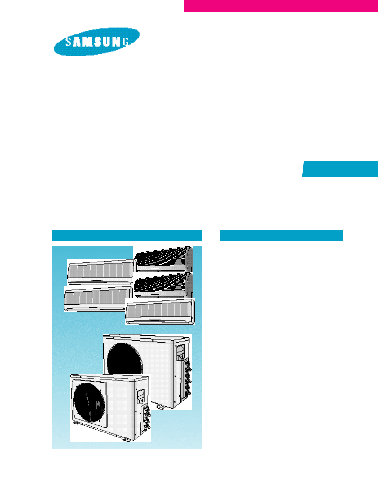
ROOM AIR CONDITIONER
INDOOR UNIT
AM14A1(B1)E07
AM20A1(B1)E06
AM20A1(B1)E08
SERVICE
OUTDOOR UNIT
UM14A1(B1)E2
UM20A1(B1)E3
Manual
CONTENTSAIR CONDITIONER
1. Pre c a u t i o n s
2. Product Specifications
3. Operating Instructions and
I n s t a l l a t i o n
4. Disassembly and Reassembly
5. Tro u b l e s h o o t i n g
6. Exploded Views and Parts List
7. Block Diagrams
8. PCB Diagrams
9. Wiring Diagrams
10. Schematic Diagrams

© Samsung Electronics Co., Ltd. MAR. 1999.
Printed in Korea.
Code No. DB81-10184A(1)
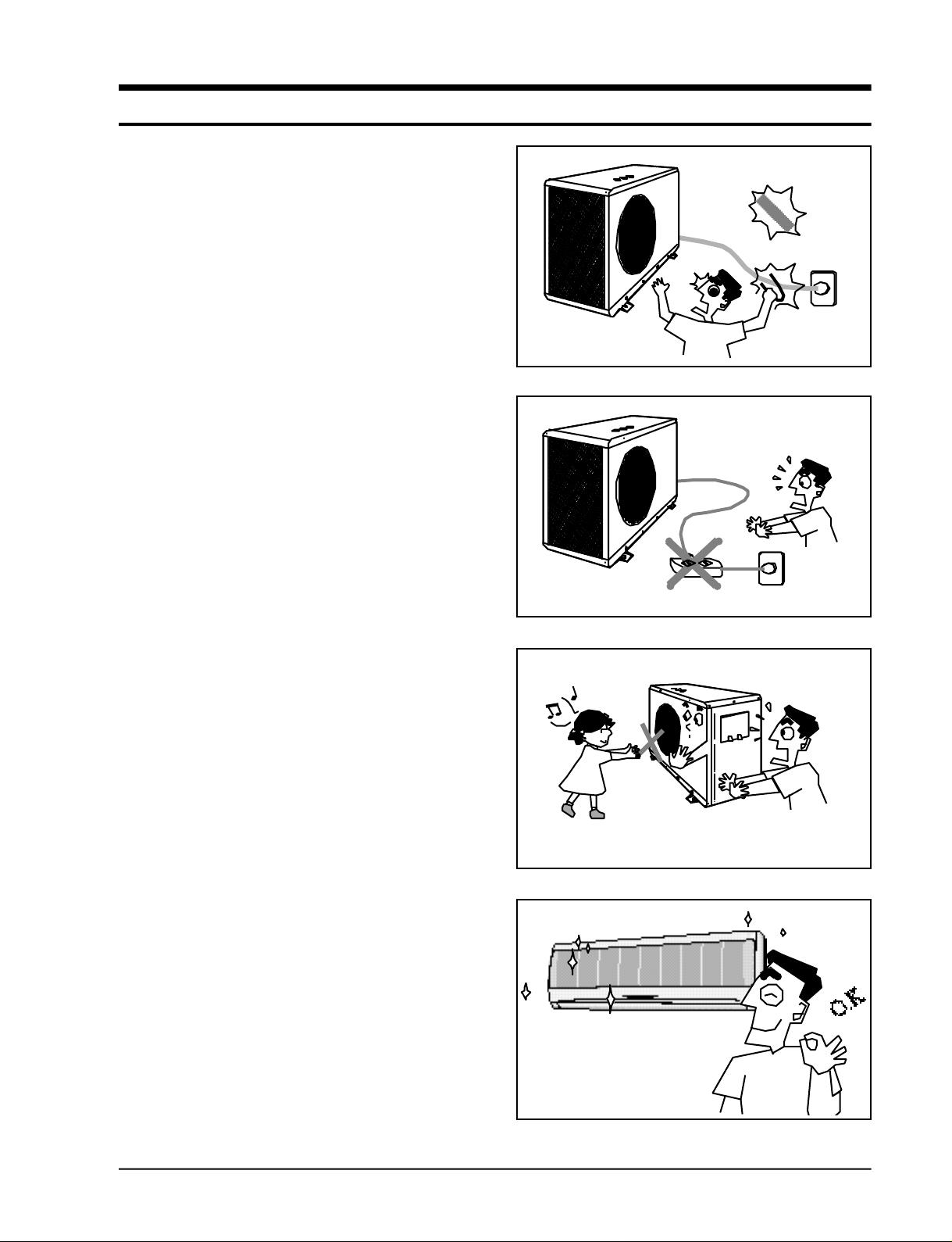
1. Precautions
1 . Warning: Prior to re p a i r, disconnect the
power cord from the circuit bre a k e r.
2 . Use proper parts: Use only exact
replacement parts. (Also, we re c o m m e n d
replacing parts rather than repairing them.)
3 . Use the proper tools: Use the proper tools
and test equipment, and know how to use
them. Using defective tools or test
equipment may cause problems laterintermittent contact, for example.
4 . Power Cord: Prior to re p a i r, check the power
c o rd and replace it if necessary.
5 . Avoid using an extension cord, and avoid
tapping into a power cord. This practice
may result in malfunction or fire .
6 . After completing repairs and re a s s e m b l y,
check the insulation resistance. Pro c e d u re :
Prior to applying power, measure the
resistance between the power cord and the
g round terminal. The resistance must be
g reater than 30 megohms.
Fig. 1-1 Avoid Dangerous Contact
Fig. 1-2 No Tapping and No Extension Cords
7 . Make sure that the grounds are adequate.
8 . Make sure that the installation conditions
a re satisfactory. Relocate the unit if
n e c e s s a r y.
9 . Keep children away from the unit while it is
being re p a i re d .
1 0 . Be sure to clean the unit and its surro u n d i n g
a re a .
Fig. 1-3 No Kids Nearby!
Fig. 1-4 Clean the Unit
Samsung Electronics
1-1

M E M O
1-2
Samsung Electronics
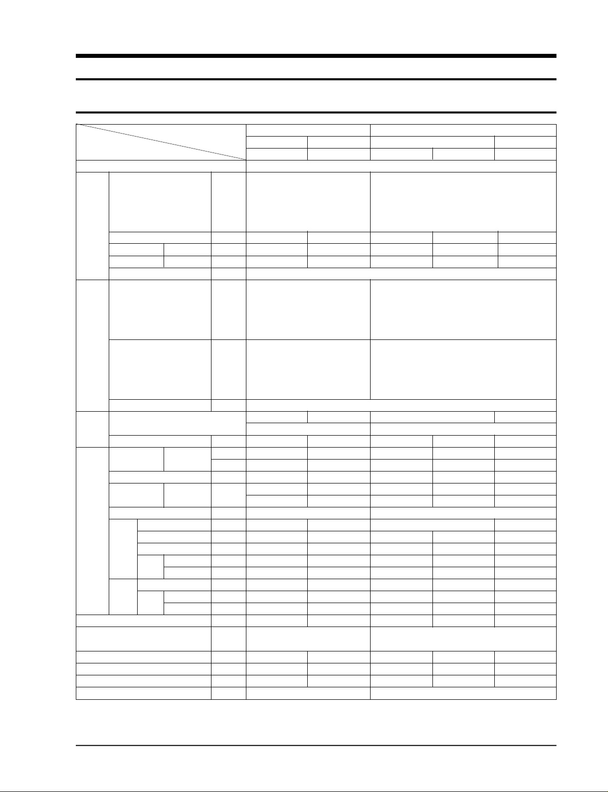
2. Product Specifications
2-1 Table
Model AM14A1(B1)E2 AM20A1(B1)E2
INDOOR UNIT OUTDOOR UNIT INDOOR UNIT OUTDOOR UNIT
Item AM14A1(B1)E07 UM14A1(B1)E2 AM20A1(B1)E08 AM20A1(B1)E06 UM20A1(B1)E3
Type Wall-Mounting Multi Split
Cooling 1 unit(A) 9,000 9,000
1 unit(B)
2 unit(A+B) 14,000 (7,000x2) 16,300 (9,000+7,300)
Performance
Power
Dehumiditying I/h 1.2 - 1.6 1.1 Air volume Cooling m3/min 7.0 - 8.5 6.0 Noise Cooling dB 35 55 38 35 54
Power V-Hz 1-220-240V~, 50Hz
Power 1 unit(A) 1,100 1,010
Consumption 1 unit(B) 1,100 930
Operating 1 unit(A) 4.7 4.3
Current 1 unit(B) 4.7 3.9
Starting current A 30
Power cable(Option)
Fuse capacity A 3.15 - 3.15 3.15 Outer
dimension xDepth inch 32.08x11.73x7.17 28.35x20.67x9.65 32.08x11.73x7.17 29.33x10.23x6.96 30.98x24.41x12.6
Weight kg 9.6 35 9.6 8.0 54
Refrigerant Liquid
pipe Gas 9.52x5 - 9.52x5 9.52x5 Drain hose
Size
Comp Capacitor 30µFx420VAC 30µFx370VAC 40µFx450VAC ressor
Blower
Heat exchanger 2Row 12Step 2Row 20Step 2Row 12Step 2Row 10Step 2Row 24Step
Refrigerant control unit
Freezer oil capacity - 410 360 350 Refrigerant to change(R-22) - 1,000 700 860 630/860
Protection device - MRA12030-12008 MRA12037-12007 MRA12054-12008 -
Standard Conditions ISO R5151 Standard ISO R5151 Standard
• The basic performance test is based on the piping of 5MT.(Be sure to check the installing conditions as extension of the piping may lead to
performance degradetion.)
2 unit(B+C) - 10,800 (5,400+5,400)
3 unit(A+B+C)
2 unit(A+B) W 1,200 1,800
2 unit(B+C) - 1,010
3 unit(A+B+C)
2 unit(A+B) A 5.2 7.5
2 unit(B+C) - 4.3
3 unit(A+B+C)
WidthxHeight
Type - Rotary - Rotary
Model name - 48A124JV1E5 44B092JW1E6 44B102JW1EG -
Type(model) - - - - -
Motor
Rated output W - 1210 895 950 -
Type Cross-fan Propeller Cross-fan Cross-fan Propeller
Type Resin Still Resin Resin Still
Motor
Rated output W 35 60 35 35 60
BTU/h
mm 815x298x182 720x525x245 815x298x182 745x260x177 787x620x320
OD(mm)xL(m)
ID(mm)xL(m)
6.35x5 - 6.35x5 6.35x5 -
A+B-UNIT : Capillary Tube
9,000 7,300
- 19,800(9,000+5,400+5,400)
- 1,900
- 8.2
- H05RNF25 - H07RNF2.5
H05RNF (4G 1mm2) H05RNF (4G 1mm2)
17x2,000 17x2,000
+ Solenoid valve
A+B/C-UNIT : Capillary Tube + Solenoid valve
Samsung Electronics
2-1
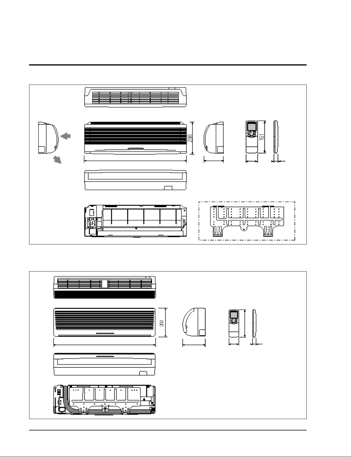
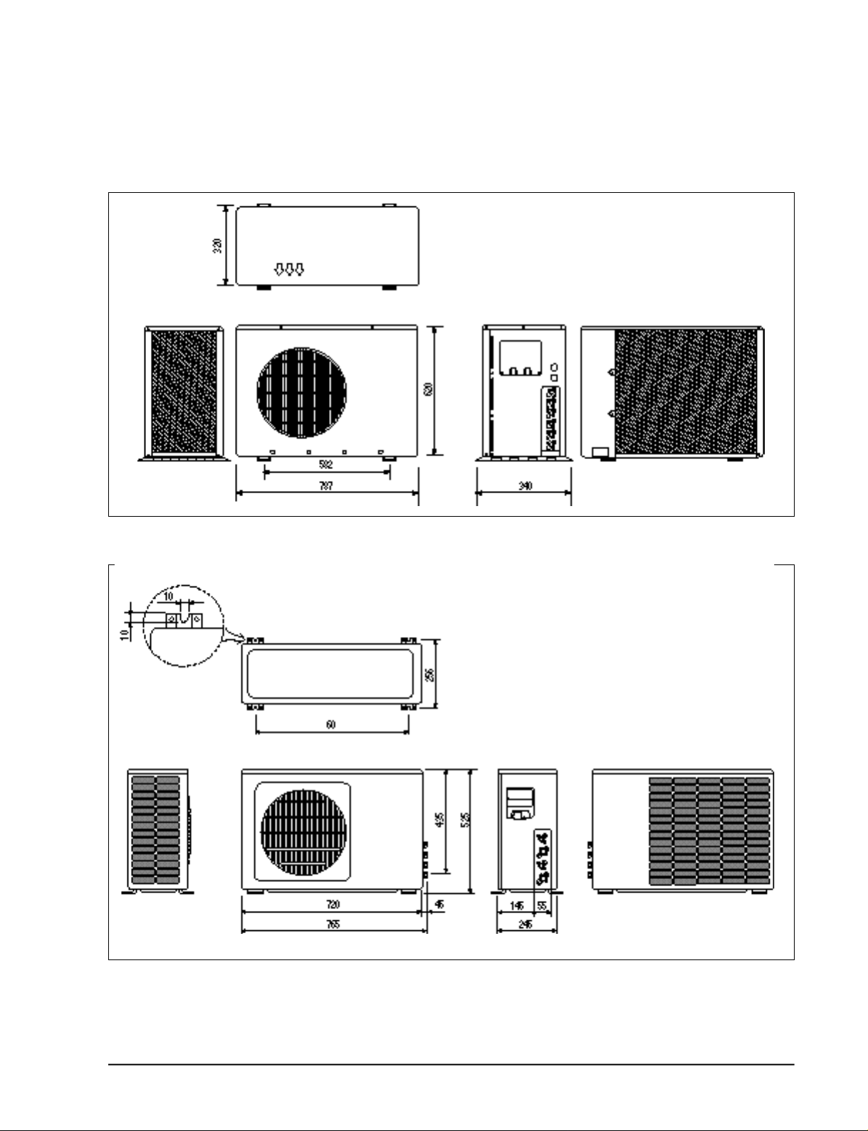
2-2 Dimensions
2-2-1(a) Indoor Unit (AM14A1(B1)E07/AM20A1(B1)E08)
(Front view)
Air
in
Air out
(Rear view)
2-2-1(b) Indoor Unit (AM20A1(B1)E06)
815 182
(Remote control)
58
22
Installation plate
2-2
(Front view)
(Rear view)
745
(Remote control)
58177
22
Samsung Electronics
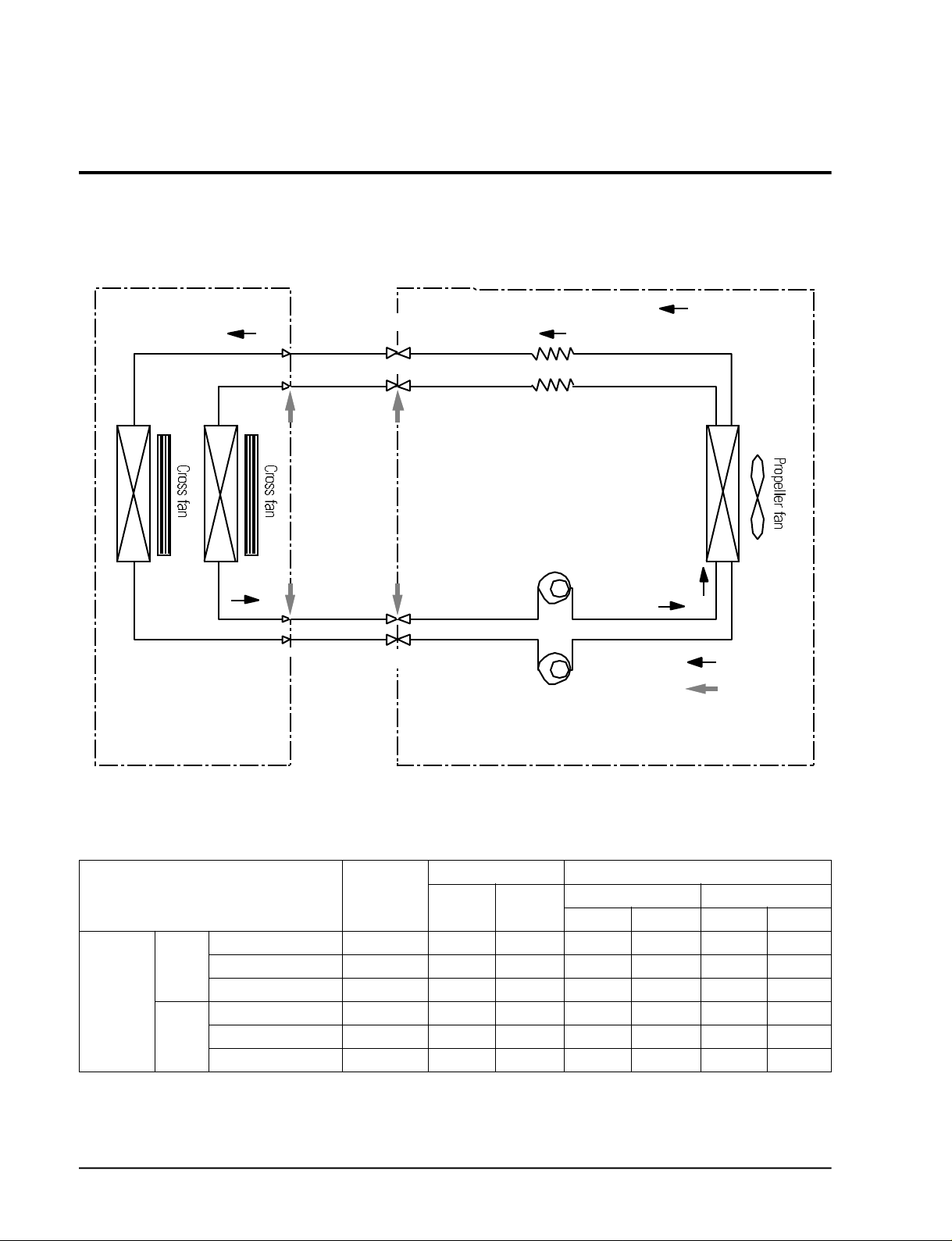
2-2-2 Outdoor Unit
2-2-2(a) UM20A1(B1)E3
Product Specifications
2-2-2(b) UM14A1(B1)E2
(Front view)
(Rear view)
Samsung Electronics
(Front view)
(Rear view)
2-3
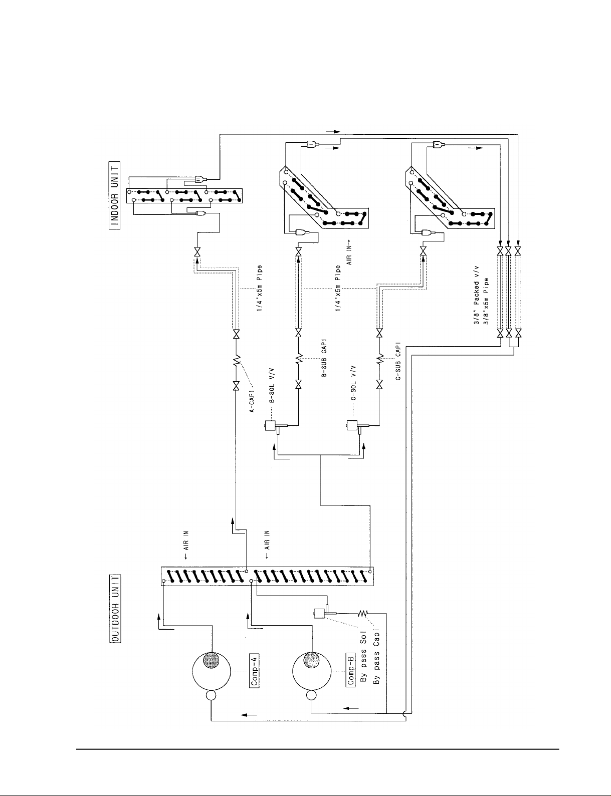
2-3 Refrigerating Cycle Block Diagram
2-3-1(a) UM14A1(B1)E2
INDOOR UNIT
(A) (B)
Heat
exchanger
(Evaporator)
T1
Liquid side
T2 Gas side
2-way valve
3-way valve
OUTDOOR UNIT
Capillary tube
Compressor-B
Compressor-A
Heat
exchanger
(Condenser)
Cooling
Gas leak
check point
Refrigerating cycle temperature and pressure
STD Pressure Piping Temp.(°C) Temp. Condition (°C)
Operating Condition (kg/cm2G)
3-way valve DB WB DB WB
Standard 5.0~5.2 11 11 27 19 35 24
A or B Max over load 6.0~6.3 16 15 32 23 43 26
Cooling Low temp. 3.4~3.6 3 2 21 15 21 15
Standard 5.0~5.2 12 10 27 19 35 24
A + B Max over load 6.0~6.3 16 15 32 23 43 26
Low temp. 3.4~3.6 3 2 21 15 21 15
2-4
T1 T2
Indoor Outdoor
(Pipe Length:5m)
Samsung Electronics
2-3-2(b) UM20A1(B1)E3
Product Specifications
Samsung Electronics
2-5

M E M O
2-6
Samsung Electronics
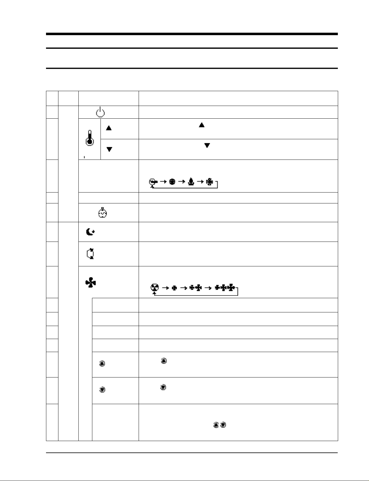
3. Operating Instructions and Installation
3-1 Operating Instructions
3-1-1 Name & Function of Key in remote controller
NO
NAMED OF KEY
1
2
3
MODE
4
5
6
7
8
TURBO
OFF
(UP)
(DOWN)
On/Off Button. Use this button to start and stop air conditioner.
Temp. up button. If the button is pressed once,
the setting temperature is increased by 1°C
Temp. down button. If the button is pressed once,
the setting temperature is decreased by 1°C
Each time you press this button,
MODE is changed in the following order.
Use this button to provide heavy duty cooling & Heating for 30 minutes.
Set up the reserve or cancel the timer on and timer off quickly
Use this button for sleep operation.
(The SLEEP mode can be selected at COOL and HEAT mode.)
Adjusts air flow vertically.
Each time you press this button,
BLADE-H rotates by 10.58° (Changable range 42.3°)
Each time you press this button,
FAN SPEED is changed in the following order.
FUNCTION OF KEY
9
C
O
10
V
E
R
11
12
13
14
15
Samsung Electronics
T
I
M
E
R
ON TIMER
OFF TIMER
SET
CANCEL
TIME
(UP)
(DOWN)
Set up the time that operation start.
Set up the time that operation stop.
Use this button to reserve the timer on.
Use this button to reserve or cancel the timer on and timer off.
If the button is pressed once, the time increase by one minute
during the time set mode, and ten minutes during the timer set mode.
If the button is pressed once, the time decrease by one minute
during the time set mode, and ten minutes during the timer set mode.
Without regard to ON/OFF condition in remote controller,
use this button to set current time.
Adjust the current time using button.
(Data can be transmitted after setting up the time)
3-1
Operating Instructions and Installation
3-1-1 Name & Function of Key in remote controller
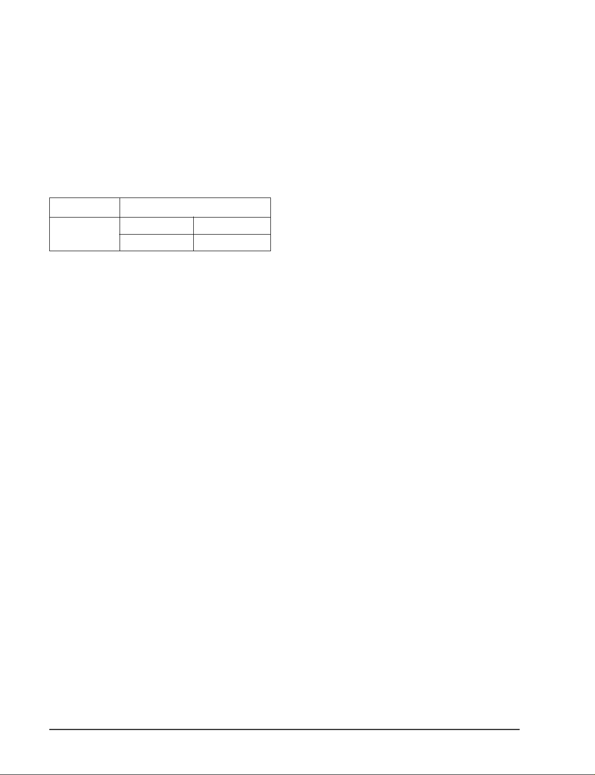
1. A U TO MODE : In this mode, operation
C O O L mode is selected automatically by the
room temperature of initial operation.
Operation Type
Tr≥ 24.5°C+∆T Compressor ON
Cool Operation
Tr≤ 24°C+∆T Compressor OFF
∆T= -1°, -2°C, 0°C+1°C+2°C
∆T is controlled by setting temperature
up/down key of remote contro l l e r
* FAN SPEED : A U TO
2. C O O L MODE : The unit operates accord i n g
to the diff e rence between the setting and
room temperature. (18°C~30°C)
3. D RY MODE : Has 3 states, each determined
by room temperature .
The unit operates in DRY m o d e .
*Co m p ressor ON/OFF Time is contro l l e d
compulsorily(can not set up the fan speed,
always bre e z e ) .
* P rotective function : Low temperature
release. (Prevention against fre e z e )
Room Temp
4. TURBO MODE : This mode is available in
A U TO, COOL, DRY, FAN MODE.
When this button is pressed at first, the air
conditioner is operated “powerful” state for
30 minutes re g a rdless of the set temperat u re, room temperature .
When this button is pressed again, or when
the operating time is 30 minutes, turbo
operation mode is canceled and returned to
the previous mode.
*But, if you press the TURBO button in DRY
or FAN mode that is changed with A U TO
mode automatically.
5 . S L E E P MODE : Sleep mode is available
only in COOL m o d e .
The operation will stop after 6 hours.
*In COOL mode : The setting temperature
is automatically raised by 1°C each 1hour
When the temperature has been raised by
total of 2°C, that temperature is maint a i n e d .
6. FAN SPEED : Manual (3 step), Auto (4 step)
Fan speed automatically varies depending
on both the diff e rence between setting and
the room temperature .
3-2
Samsung Electronics
Operating Instructions and Installation
7 . C O M P U L S O RY O P E R ATION :
For operating the air conditioner without
the remote contro l l e r.
* A U TO : The operating is the same function that A U TO MODE in the remote cont ro l l e r.
8 . SWING : BLADE-H is rotated vertically by
the stepping motor.
*Memory louver : When ON/OFF button is
p ressed at stop state, the BLADE-H re t u r n s
to its original location which is operating
state before stop
*Swing auto : The BLADE-H can ro t a t e
within about 10,500 in the original position
set by the SWING SET button.
*Swing Set : Press the button under the
remote control is displayed on LCD the ,
and the blades move up and down, about 43°.
If the one more time press the button, blatles location is stop.
9 . Quick OFF TIMER: OFF timer (quick timer)
allows reservation or cancel the timer on
and timer off quickly
When OFF timer button is pressed at operating state, LCD displays the polling state
s e q u e n t i a l l y.
The LCD also displays the time re m a i n i n g .
1 0 . 24-Hour ON/OFF Real Setting Ti m e r. : The
air conditioner is turned ON at a specified
time using .
ON TIMER
OFF TIMER : The air Conditioner is turned
OFF at a specified time using .
OFF TIMER
*ON TIMER : Only timer LED lights on.
*OFF TIMER : Both timer and operation
LED lights on.
*3 minutes delay timer.
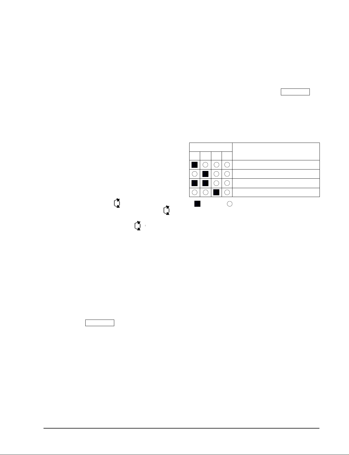
11 . SELF Diagnosis
LED DISPLAY
o p e r-
T I M E R
a t i o n
FA N
Tu r b o
Check Point
I n t e r ruption of electric power and Power on.
Abnormal condition of the room sensor.
Abnormal condition of the indoor unit's heat exchanger sensor.
Indoor unit fan motor lock.
L E D
:
b l i n k i n g
: LED off
1 2 . TIME SHORTENING : If the "Time short"
connector pin is shorted on the main P. C. B,
the compressor's three minutes delay function is cancelled, and each operation time is
shortened to one fiftieth of its original time.
1 3 . BUZZER SOUND : Whenever the ON/OFF
button is pressed or whenever change
occurs to the condition which is set up or
select, the compulsory operation mode,
buzzer is sounded "beep"
Samsung Electronics
3-3

3-2. Outdoor unit controlling spec (Each load controlling condition)
3-2-1 Indoor unit signal(Rooms "B",
and "C" signal)
1 ) On condition : A time point where the
d e s i red temperature at each indoor unit is
+0.5°C against the current temperature .
(When the compressor motor relay of each
assembly main PCB is turned on.)
2) O ff condition : A time point where the
d e s i red temperature at each indoor unit is
against the current temperature. (When the
c o m p ressor motor relay of each assembly
main PCB is turned off . )
3-2-2 SV-BY control
1) On condition :
•When only any one of the two indoor unit
rooms (Rooms B and C) is turned on.
•F o rce it to operate for about 2 minutes
seconds when both of the two indoor unit
rooms (Rooms B and C) are turned off .
2) O ff condition :
•When all of the two indoor unit rooms
(Rooms B and C) are turned on.
•It is automatically turned off after
operating for about 2 minutes
+3 0
- 0
seconds when all of the two indoor unit
rooms (Rooms B and C) are turned off .
3-2-3 SV-B(Indoor unit room "B"
solenoid valve) control
SV-C(Indoor unit room "C"
solenoid valve) control
1) On condition :
•Only the SV-B solenoid valve operate
when the indoor unit room "B" is turned
o n .
•Only the SV-C solenoid valve operate
when the indoor unit room "C" is turned
o n .
•Both of the SV-B and SV-C solenoid valves
operate when all of the indoor unit room B
+ 3 0
- 0
and room C are activated.
•When both of the indoor unit room B and
room C are turned off, it is forced to operate for about 2 minutes seconds.
+3 0
- 0
2) O ff condition :
•The SV-C solenoid valve is turned off
when the indoor unit room "B" is operated.
•The SV-B solenoid valve is turned off
when the indoor unit room "C" is operated.
•When both of the indoor unit room "B"
and room "C" are turned off, it is automatically turned off after operating for about 2
minutes seconds.
+3 0
- 0
3-2-4 Compressor control
1) F o rce the compressor to stop for 3 minutes
at each indoor unit when applying power to
two rooms of the indoor unit(Room "B", and
room "C"). (Delayed operation for thre e
m i n u t e s )
2) A delay time of about 2 minutes 30 seconds
is set up at the outdoor unit PCB when
turning it off (Both of the rooms B and C are
turned off) by comparing the desired temp e r a t u re at each indoor unit against the
c u r rent temperature .
3) When both rooms (Rooms B and C) of the
indoor unit are turned off, force the comp ressor to stop, and then turn on the SV- B Y,
S V-B (room "B" valve), and SV-C (room C
valve) to achieve the pre s s u re balance of the
c o m p re s s o r.
4) When applying the power to the outdoor
unit PCB initially, disre g a rd the time of
f o rcing the outdoor unit compressor (About
2 minutes seconds).
+3 0
- 0
3-4
Samsung Electronics
Operating Instructions and Installation
3-2-5 Outdoor unit fan motor control (1 step)
1) On condition : When the compressor is "ON".
2) O ff condition : When the compressor is "OFF".
3) The motor is operated in "High" rpm mode re g a rdless of the number of the indoor units
o p e r a t e d .
(Note)
1. C o n t rolling the solenoid valve of the outdoor unit according to the operation of the indoor
units (Room B, Room C)
Combination of indoor units Control of solenoid valve Remarks
Room "B" Room "C" SV-B SV-C SV-BY
Room 0 • • • Off after operating for about 2 minutes seconds
Room 1 • • •
• • •
Room 2 • • • •
+ 30
- 0
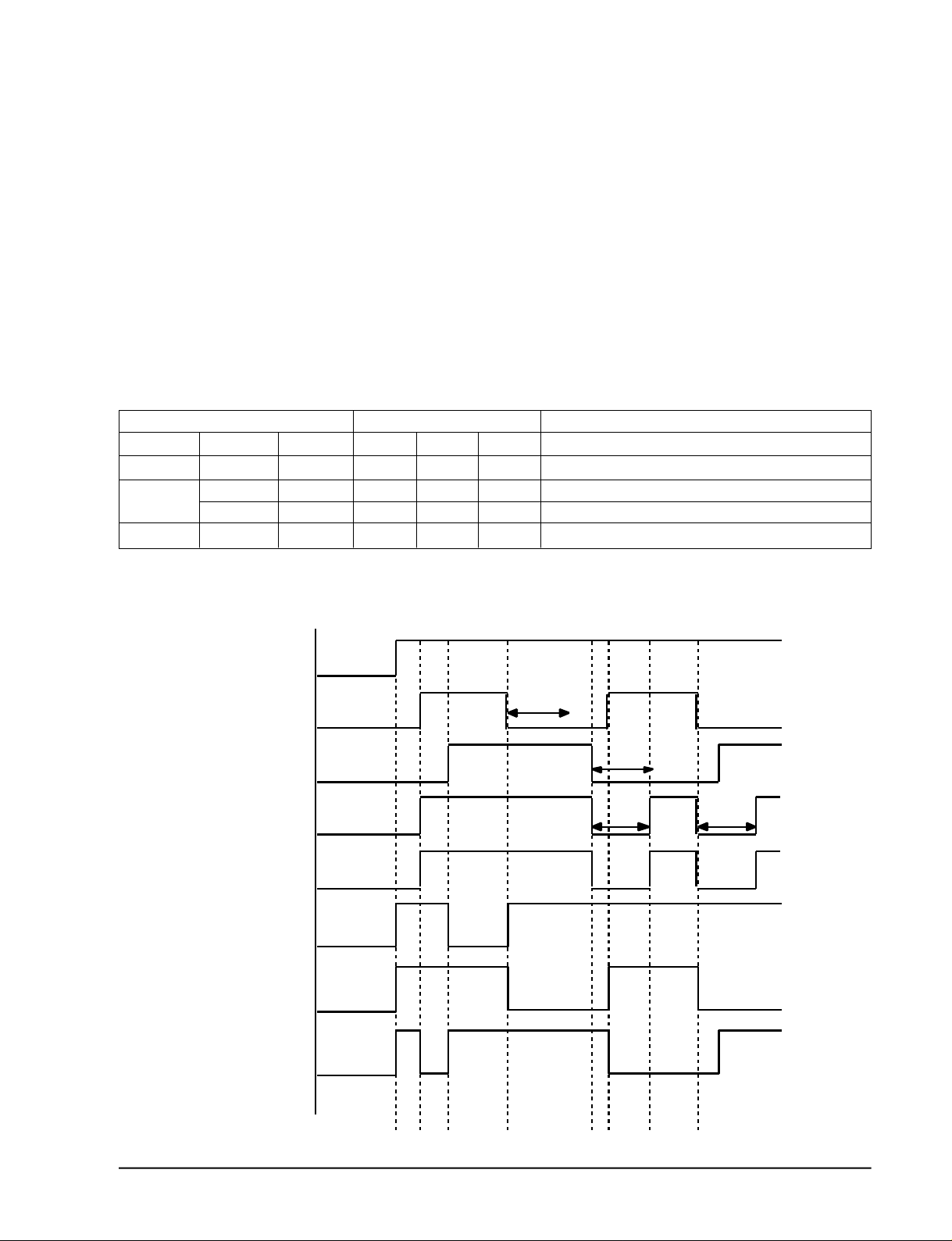
2. Outdoor unit load time chart according to the operating conditions for the indoor unit.
Outdoor unit power supply
Delay of 3 minutes
Indoor unit room "B"
Delay of 3 minutes
Indoor unit room "C"
About 2 minutes About 2 minutes
Compressor
Outdoor fan motor
SV-BY
SV-B (room"B"
soldnoid valve)
SV-C (room"C"
soldnoid valve)
Samsung Electronics
3-5

3-3 Installation
3-3-1 Selecting Area for Installation
Select an area for installation that is suitable
to the customer's needs.
3-3-1(a) Indoor Unit
1 . Make sure that you install the indoor unit in
an area providing good ventilation. It must
not be blocked by an obstacle affecting the
airflow near the air inlet and the air outlet.
2 . Make sure that you install the indoor unit in
an area allowing good air handling and
endurance of vibration of the indoor unit.
3. Make sure that you install the indoor unit in
an area where there is no source of heat or
vapor nearby.
4 . Make sure that you install the indoor unit in
an area from which hot or cool air is spre a d
evenly in a ro o m .
5 . Make sure that you install the indoor unit in
an area away from TVs, audio units, cordless phones, fluorescent lighting fixture s
and other electrical appliances (at least 1
m e t e r ) .
6 . Make sure that you install the indoor unit in
an area which provides easy pipe connection with the outdoor unit, and easy
drainage for condensed water.
7. Make sure that you install the indoor unit in
an area which is large enough to accomodate the measurements shown in figure on
the next page.
3-3-1(b) Outdoor Unit
1 . Make sure that you install the outdoor unit
in area not exposed to the rain or direct sun
l i g h t .
(Install a separate sunblind if exposed to
d i rect sun light.)
2 . Make sure that you install the outdoor unit
in area allowing good air moment, not
amplifying noise or vibration, especially to
avoid disturbing neighbours.
(Fix the unit firmly if it is mounted in a
high place.)
3 . Make sure that you install the outdoor unit
in area providing good ventilation and
which is not dusty. It must not be blocked
by any obstacle affecting the airflow near
the air inlet and the air outlet.
4 . Make sure that you install the outdoor unit
in area free from animals or plants.
5 . Make sure that you install the outdoor unit
in area not blocking the traff i c .
6. Make sure that you install the outdoor unit
in area easy to drain condensed water fro m
the indoor unit.
7. Make sure that you install the outdoor unit
in area which provides easy connection
within the maximum allowable length of a
coolant pipe(15 meters).
Note
1. Add 10 grams of refrigerant (R-22) for
every 1 meter if the pipe length exceeds
the standard pipe length of 5 meters.
2. Maintain a height between the indoor and
outdoor units of less than 3 meters.
8 . Make sure that you install the outdoor unit
in an area which is large enough to accommodate the measurements
shown in figure on the next page.
3-3-1(c) Remote Control Unit
1 . Make sure that you install the remote con-
t rol unit in an area free from obstacles such
as curtains etc, which may block signals
f rom the remote control unit.
2. Make sure that you install the remote cont rol unit in an area not exposed to
d i rect sunlight, and where there is no sourc e
of heat.
3. Make sure that you install the remote cont rol unit in an area away from TVs, audio
units, cordless phones, fluorescent lighting
f i x t u res and other electrical appliances (at
least 1 meter).
Caution :
It is harmful to the air conditioner if it is used in the following environments: greasy areas (including areas near machines),
salty areas such as coast areas, areas where sulfuric gas is present such as hot spring areas. Contact your dealer for advice.
3-6
Samsung Electronics
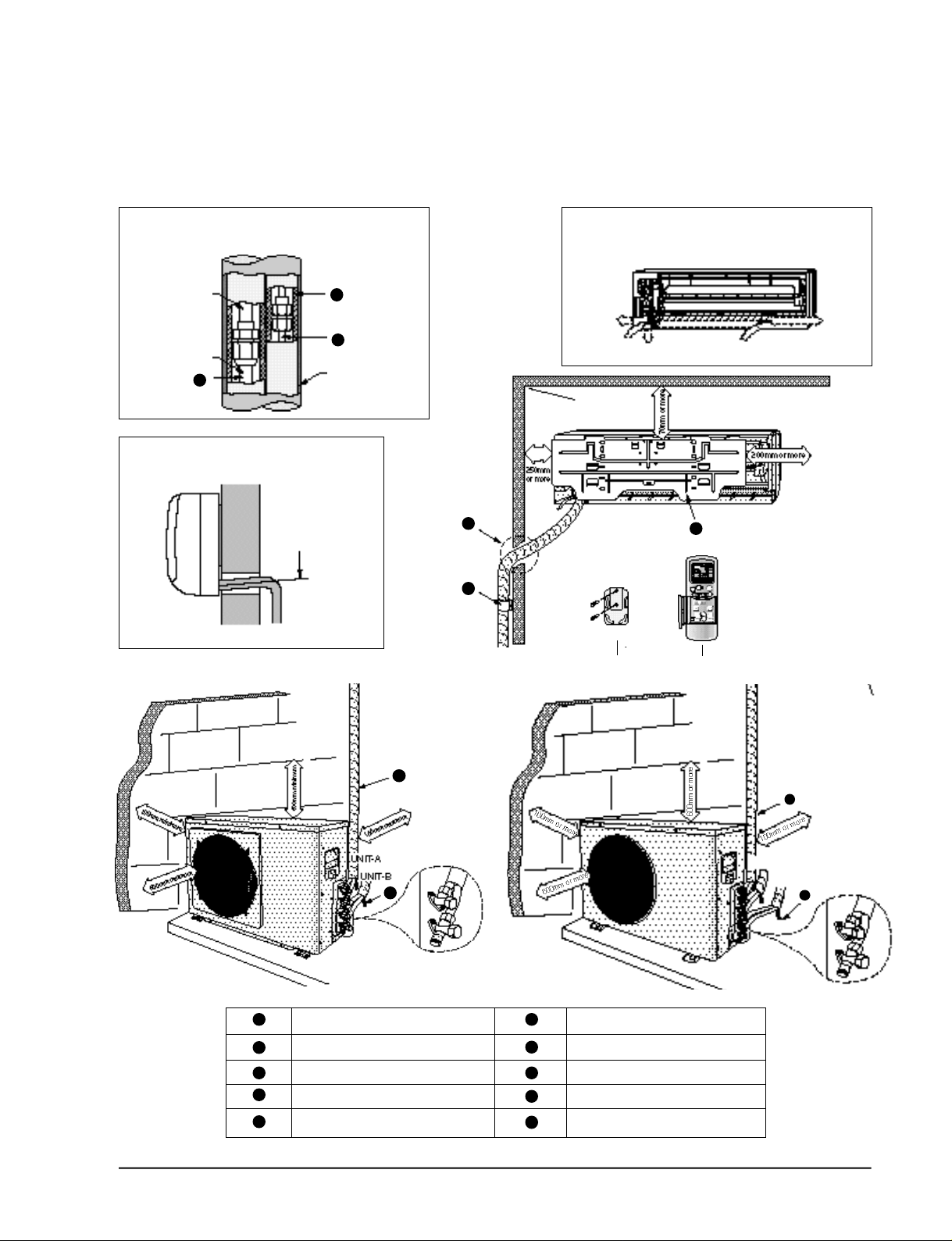
3-2-2 Installation diagram of indoor unit and outdoor unit
Operating Instructions and Installation
A Indoor unit gas leak test check point
Indoor unit
Piping
1
3
2
Tape vinyl
B Drain hose installation
Cut the piping hole
sloped slightly
Piping may be laid to the rear, left,
right or down .
Right
Rear
5
6
Down
Remote controlRemote control holder
Rear
7
Left
1
2
3
4
5
Samsung Electronics
4
10
Piping (Liquid) 1/4” Clamper tube
Piping (Gas) 3/8” Installation plate
Installation tube Pipe-connection
Vinyl tape Screw
Putty Drain hose
6
7
8
9
10
UNIT-A
UNIT-B
4
Outdoor unit check point
UNIT-C
10
3-7
Operating Instructions and Installation
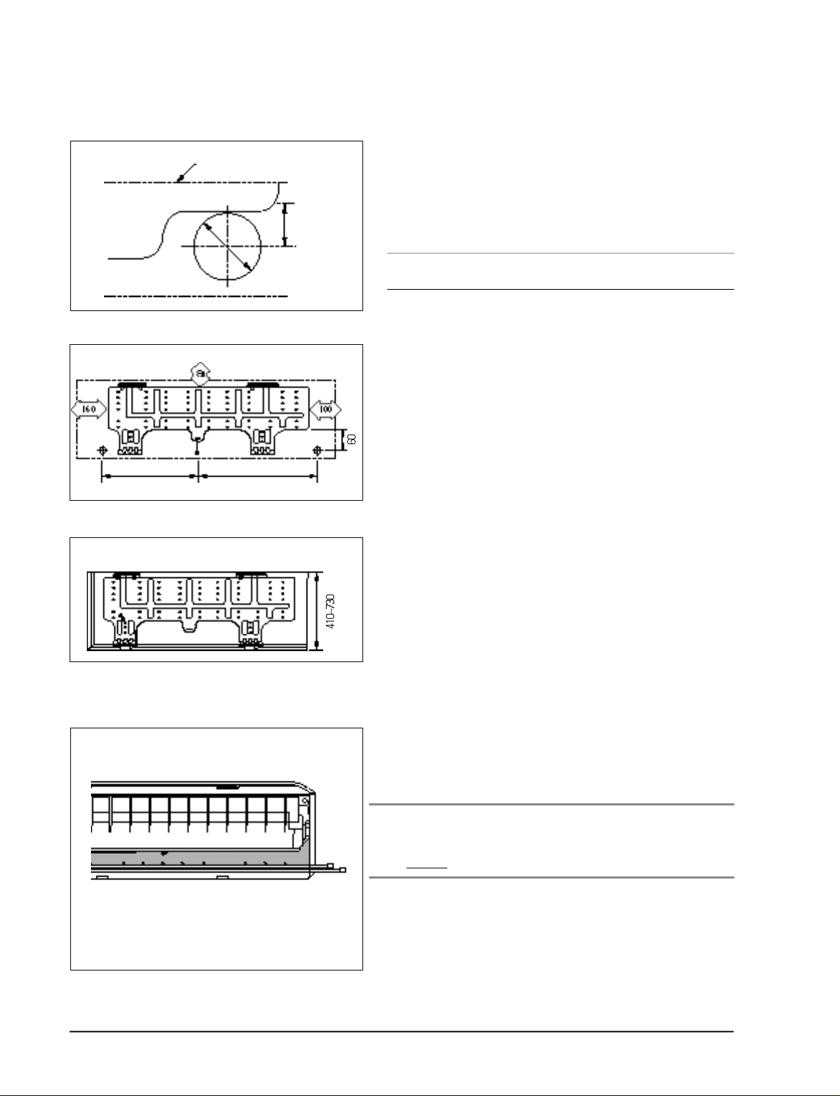
3-3-2(a) Fixing the Installation Plate
(Unit : mm)
(Unit : mm)
Installation plate
280
340
Pipe hole
(ø65mm)
1. Determine the position of the pipe and drain hose hole
using the right figure and drill the hole with an inner
diameter of 65mm so that it slants slightly downwards.
2. If you are fixing the indoor unit to a… Then follow Steps…
Wall 3.
Window frame 4 to 6.
3. Fix the installation plate to the wall in a manner appropriate to the weight of the indoor unit.
If you are mounting the plate on a concrete wall with
anchor bolts, the anchor bolts must not project by more
than 20mm.
4. Determine the positions of the wooden uprights to be
attached to the window frame.
3-3-2(b) Purging the Unit
5. Attach the wooden uprights to the window frame in a
manner appropriate to the weight of the indoor unit.
6. Using tapped screws, attach the installation plate to the
wooden uprights, as illustrated in the last figure opposite.
On delivery, the indoor unit is loaded with an inert gas.
All this gas must therefore be purged before connecting the
assembly piping. To purge the inert gas, proceed as fol lows.
Unscrew the caps at the end of each pipe.
Result : All inert gas escapes from the indoor unit.
• To prevent dirt or foreign objects from getting into
the pipes during installation, do NOT remove the
caps completely until you are ready to connect the
piping.
3-8
Samsung Electronics
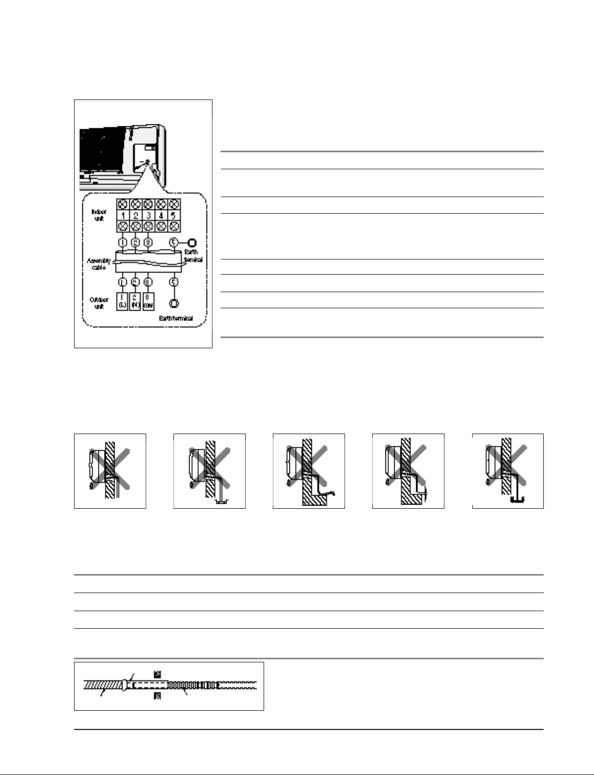
3-3-2(c) Connecting the Assembly Cable.
The outdoor unit is powered from the indoor unit via the assembly
cable. If the outdoor unit is more than five metres away from the
indoor unit, the cable must first be extended to a maximum of
ten metre s .
1 . Extend the assembly cable if necessary.
2 . Open the front grille by pulling on the tabs on the lower right and
left sides of the indoor unit.
3 . Remove the screw securing the connector cover.
4 . Pass the assembly cable through the rear of the indoor unit and
connect the assembly cable to terminals 1 to 5.
• Each wire is labelled with the corresponding terminal number.
5 . Pass the other end of the cable through the 65mm hole in the wall.
6 . Replace the connector cover, carefully tightening the scre w.
7 . Close the front grille.
8 . For further details on how to plug the other end of the assembly
cable into the outdoor unit, refer to page 3-10.
Operating Instructions and Installation
3-3-2(d) Installing and Connecting the Indoor Unit Drain Hose
C a re must be taken when installing the drain hose for the indoor unit to ensure that any condensa tion water is correctly drained outside.l When passing the drain hose through the 65mm hole drilled
in the wall, check that none of the following situations occur.
The hose must
NOT slope upw
ards.
To install the drain hose, proceed as follows.
1. If necessary, connect the 2-metre extension to the drain hose.
2 . If you are using the extension, insulate the inside part of the extension drain hose with a shield.
3. Pass the drain hose under the refrigerant piping, taking care to keep the drain hose tight.
4. Pass the drain hose through the hole in the wall, making sure that it is sloping downwards, as
shown in the illustrations above.
The end of the drain
hose must NOT be
placed in water.
Do NOT bend the
hose in different
directions.
Keep a clearance of at
least 5cm between the
end of the hose and the
ground.
Do NOT place the end
of the drain hose in a
hollow.
Shield
Drain hose Extension drain hose
Samsung Electronics
The hose will be fixed permanently into position once
the whole installation has been tested for gas leaks;
refer to page 16 for further details.
3-9
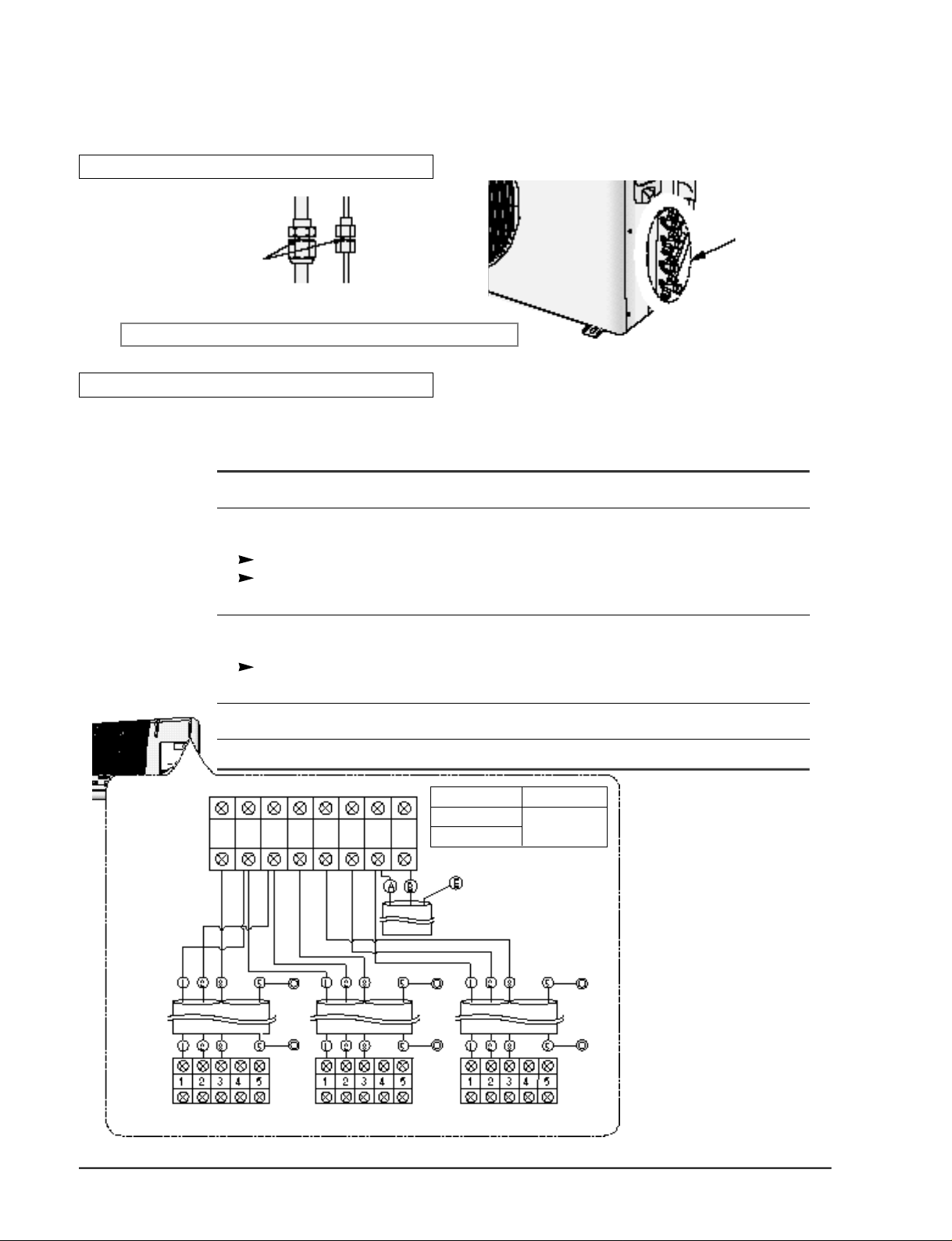
Operating Instructions and
3-3-2(e) Outdoor unit installation
GAS LEAK TEST
Indoor unit check point
Check for gas leak from the flare nut connections with leak detector.
WIRING CONNECTION
Two electric cables must be connected to the outdoor unit:
• The assembly cable connecting the indoor unit to the outdoor unit.
• The power cable connecting the auxiliary circuit breaker to the outdoor unit.
1 Remove the terminal board cover on the side of the outdoor unit.
Outdoor unit check point
Terminal Block
2 Connect the assembly cable to terminals 1 to 5 and connect the power cable to therminals A to B.
Each wire is labelled with the corresponding terminal number.
E n s u re that the wire number of the indoor unit and the terminal number of the outdoor unit.
3 Connect the earthing wires to the earth terminals.
Refer to the page opposite for further details on how to check that earthing is corre c t .
4 Replace the terminal board cover, carefully tightening the screw.
5 connect the power cable to the auxiliary circuit breaker.
Outdoor unit
1
3
(L)
COM
Earth
terminal
2
(N)
3
COM3COM
2
1
(N)
2
(L)
(N)
Indoor Unit Outdoor Unit
AM20A1(B1)E08
AM20A1(B1)E06
Earth
terminal
Circuit Breaker
(Main Power cable)
UM20A1(B1)E3
3-10
Assembly
cable
Indoor unit
A-unit
AM20A1(B1)E08
Earth
terminal
Earth
terminal
B-unit
AM20A1(B1)E06
Earth
terminal
Earth
terminal
Earth
terminal
Earth
terminal
C-unit
AM20A1(B1)E06
Samsung Electronics
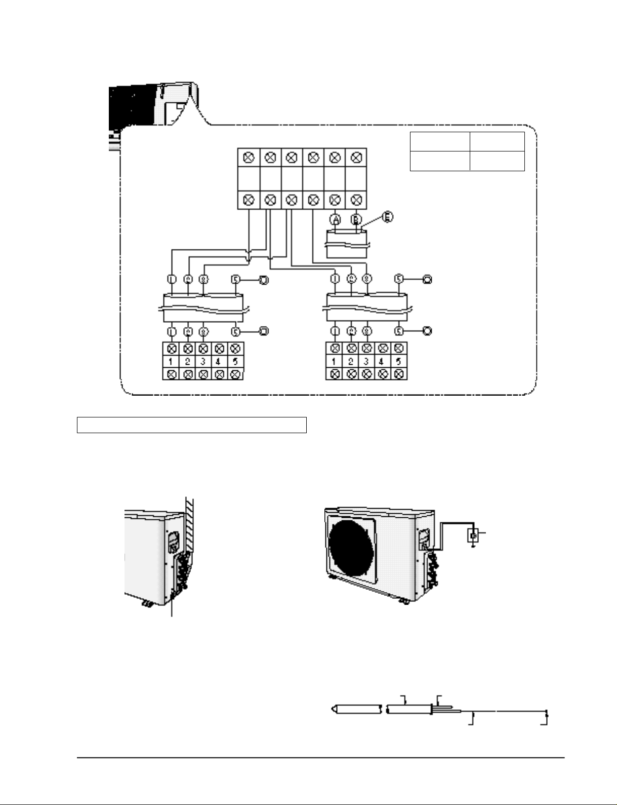
Outdoor unit
NLB21A
Operating Instructions and
Indoor Unit Outdoor Unit
AM14E1(B1)E07 UM14A1(B1)E2
Terminal Block
Earth
terminal
Circuit Breaker
(Main Power cable)
Indoor
unit
A-unit B-unit
Grounding
(The parts for this work are optional.)
• A g rounding terminal can be found on
the outdoor unit as illustrated.
Earth
terminal
Earth
terminal
Earth
terminal
Assembly cable
Earth
terminal
1 . When an existing grounding terminal is available.
( G rounding wire of ®™1.6mm or larg e r < s o l i d
w i re>or 2mm2 or larger <standard wire>)
Terminal used
exclusively for
grounding.
Grounding resistance:
less than 100 ohms
(existing grounding electrode)
Grounding screw hole
Samsung Electronics
2 . Use of a grounding electro d e .
• Specifications of grounding electro d e .
Carbon plastic Steel core
PVC-insulated wire(2mm2x3.5m), green Terminal, M4
3-11
Operating Instructions and Installation
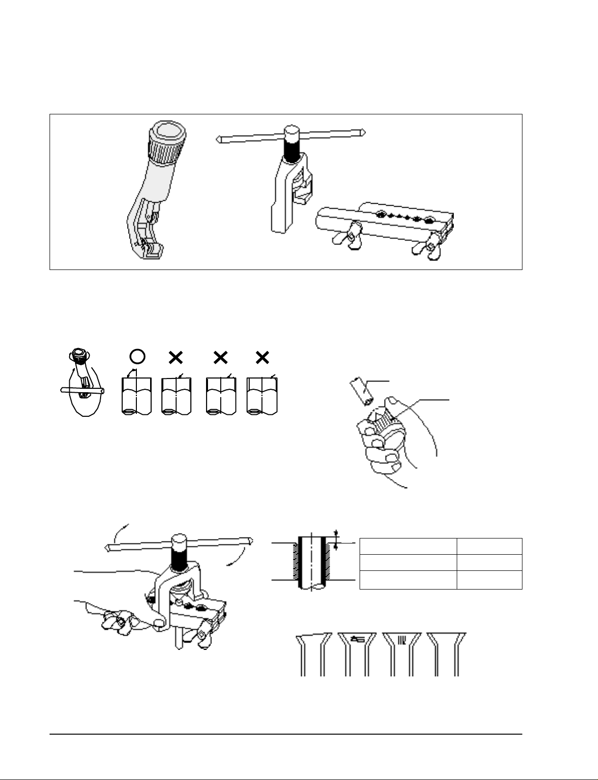
3-3-2(f) Flare Modification
• Tools used
Flare modification procedure
1 ) Cut the pipe using a pipe cutter.
90°
3 ) Insert a flare nut into the pipe and modifty flare .
Oblique
Raughness
2 ) Remove burrs at the tip of the pipe cut.
Burr
* Unproper flaring
C a u t i o n : Burrs not removed may result in
leakage of gas.
Pipe
Reamer
D
A
Outer diameter A(mm)
ø6.35mm 1.3
ø9.52mm 1.8
3-12
Inclined Surface
damaged
Cracked Uneven
thickness
Samsung Electronics
Operating Instructions and
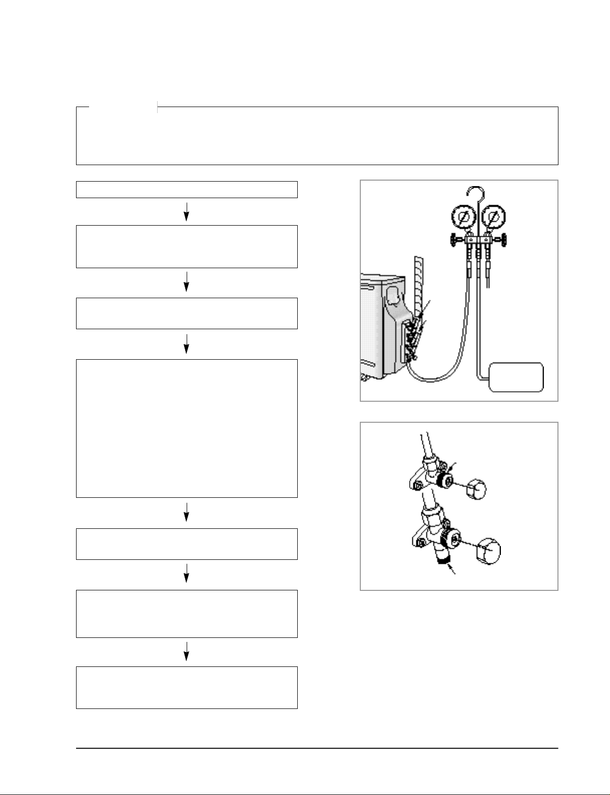
3-2-2(g) Air-Purging
CAUTION
The air in indoor unit and in the pipe must be purged. If air remains in the refrigeration pipes, it will affect the compressor,
reduce to cooling capacity, and could lead to a malfuction. Refrigerant for air purging is not charged in the outdoor unit. Use
vacuum pump as shown at the right figure. Each unit must be purged in turn
1. Check the piping connections
2. Connect the charging hose of low pressure side of
Manifold gauge to the packed valve having a service
port (3/8” or 1/2” Packed valve) as shown at the right
Indoor
3. Open the valve of the low pressure side of Manifold
gauge counterclockwise.
A-unit
Indoor
B-unit
4. Purge the air from the system using vacuum pump for
about 10 minutes.
- Close the valve of the low pressure side of manifold
gauge clockwise.
- Make sure that pressure gauge show -0.1MPa(-
76cmHg) after about 10minutes.
This procedure is very important in order to avoid gas
leak.
- Turn off the vacuum pump
- Remove the hose of the low pressure side of mani -
fold gauge.
5. Set valve cork of both liquid side and gas side of
packed valve to the open position.
6. Mount the valve stem nuts and the service port cap to
the valve, and tighten them at the torque of 18N.m
with a torque wrench.
Liquid side
Gas side
Vacuum Pump
Valve stem
Stem cap
Service port
7. Check for gas leakage.
-At this time, especially check for gas leakage from the
3-way valve’s stem nuts, and from the service port cap.
Samsung Electronics
3-13
Operating Instructions and Installation
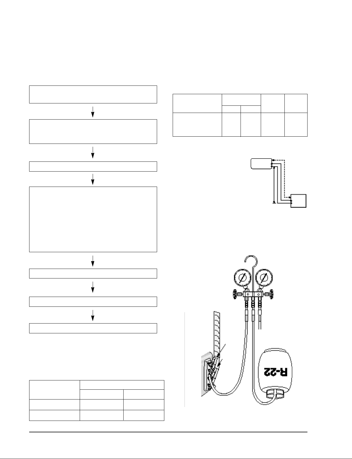
3-2-2(h) Refrigerant Refill
If connecting pipe of more than 10 metres is installed, additional refrigerant should be charged by
extra metre. You don’t have to charge additional refrigerant up to 10 metres of connecting pipe.
1. Remove the valve stem cap and service port of 3-way
valve.
2. Connect the charging hose of low pressure side of
Manifold gauge to the packed valve having a charging
port(1/2” Packed valve) as shown at the right figure.
3. Operate the unit at the cooling mode.
4. Slowly open the valve of the low pressure side of
Manifold gauge counterclockwise until the low pressure of manifold gauge indicates 4.8 to 5.5 kg/cm2 (68
a 78psi) at the high cool operation (1-unit operation)
and the standard temperature.
It is recommend that refrigerant should be slowly put
in. If the refrigerant is put in too quickly, compressor
will be damaged.
• Piping length and the height
Pipe Size
AM14A1(B1)E07
AM20A1(B1)E08
1/4” 3/8”
AM20A1(B1)E06
Additional refrigerant charg e
( R 2 2 , g )
• When length of the pipe is
over 5u by the unit, you
should charge
the refrigerant Formulas
A-UNIT : 10gx(La- 1 0 ) / m
B-UNIT : 10gx(Lb- 1 0 ) / m
( La:the length of A-unit’s
pipe Lb:the length of
B-unit’s pipe)
INDOOR UNIT
M a x . p i p i n g
length
A
15m
B
Max
height
BLIQUID GAS
3m
A
OUTDOOR UNIT
5. Stop operation of the air conditioner.
6. Disconnect the charge hose of manifold gauge.
7. Close the cap of each valve.
3-2-2(i) Flare unt fixing torque
Outter diameter
Fixing Torque Final Torque
ø6.35(Liquid Side) 160 200
ø9.52(Gas Side) 300 350
3-14
Torque (kg-cm)
INDOOR
A-UNIT
INDOOR
B-UNIT
Samsung Electronics
 Loading...