

Samsung AlphaPC 164UX, AlphaPC 164BX User Manual

AlphaPC 164UX/BX Motherboard
Windows NT
User’s Manual

Notice
The information in this publication has been carefully checked and is believed to be entirely accurate at the time of publication.
Samsung assumes no responsibi lity, however, for possible errors or omissions, or for an y consequences resulting from the use
of the information cont a ine d herein.
Samsung reserves the rig ht to m ake changes in its products or prod uct specifications with the in tent to improve function or
design at any time and without notic e and is not required to update this docume ntation to reflect s uch changes.
This publication does not convey to a purchaser of semiconductor devices described herein any license under the patent rights of
Samsung or others.
AlphaPC 164UX/BX Motherboard
Windows NT
User’s Manual
©1998 Samsung Electronics
All rights reserved. No part of this publication may be reproduced, stored in a retrieval system, or transmitted in any form or by
any means, electric or mec hanical, by photocopyi ng, rec ordi ng, or otherwise, without the prior written consent of Samsung
Electronics.
Alpha, Digital Semico nduc tor are trademarks of Digit al Equ ipment Corporation.
Samsung and Samsung logo are trademarks of Sams ung Electronics Co., Ltd.
FaxBACK and Intel are registered trademarks of Intel Corporation.
GRAFOIL is a registered trademark of Union Carb ide Cor poration.
Microsoft, MS-DOS, Windows, and Windows 95 are registered tr ade marks and Windows NT is a trademark of Microsoft
Corporation.
QLogic is a registered trademark of QLogic Corpor at ion.
SMC is a registered trademar k of Standa rd Mi crosystems Corporation.
UNIX is a registered trademark in the United States and other countries licensed exclusively through X/Open Company Ltd.
Xilinx is a trademark of Xi li nx, Incorporated.
All other trademarks and registered tradem arks are the property of their respective owners.
San #24 Nongseo-ri , Kiheung-eup
Yongin-city, Kyungki-do, Korea
449-900
FAX : 82-331-209-4492
TEL : 82-331-209-3282
Printed in the Republic of Kore a

iii
Contents
1 About This Manual
1.1 Difference between AlphaPC 164UX and 164BX. . . . . . . . . . . . . . . . . . . . . . . . . 1–1
1.2 Manual Conventions and Terminology . . . . . . . . . . . . . . . . . . . . . . . . . . . . . . . . . 1–1
2 Features of the AlphaPC 164UX Motherboard
2.1 Power Requirements . . . . . . . . . . . . . . . . . . . . . . . . . . . . . . . . . . . . . . . . . . . . . . 2–4
2.2 Environmental Requirements . . . . . . . . . . . . . . . . . . . . . . . . . . . . . . . . . . . . . . . . 2–4
2.3 Physical Parameters. . . . . . . . . . . . . . . . . . . . . . . . . . . . . . . . . . . . . . . . . . . . . . . 2–5
2.3.1 Board Measurements and Hole Locations. . . . . . . . . . . . . . . . . . . . . . . . . . . 2–5
2.3.2 Vertical Clearance . . . . . . . . . . . . . . . . . . . . . . . . . . . . . . . . . . . . . . . . . . . . . 2–6
2.3.3 ATX Cutout Information. . . . . . . . . . . . . . . . . . . . . . . . . . . . . . . . . . . . . . . . . 2–8
3 AlphaPC 164UX Jumper Configuration
3.1 CPU Speed Selection (Option 1,2,3,&4). . . . . . . . . . . . . . . . . . . . . . . . . . . . . . . . 3–2
3.2 Bcache Size Jumpers (Option 14,15). . . . . . . . . . . . . . . . . . . . . . . . . . . . . . . . . . 3–3
3.3 Boot Option Jumper (Option 11). . . . . . . . . . . . . . . . . . . . . . . . . . . . . . . . . . . . . . 3–3
4 AlphaPC 164UX Connector Pinouts
4.1 PCI Bus Connector Pinouts . . . . . . . . . . . . . . . . . . . . . . . . . . . . . . . . . . . . . . . . . 4–1
4.2 ISA Expansion Bus Connector Pinouts. . . . . . . . . . . . . . . . . . . . . . . . . . . . . . . . . 4–3
4.3 SDRAM DIMM Connector Pinouts . . . . . . . . . . . . . . . . . . . . . . . . . . . . . . . . . . . . 4–4
4.4 EIDE Drive Bus Connector Pinouts. . . . . . . . . . . . . . . . . . . . . . . . . . . . . . . . . . . . 4–5
4.5 Diskette Drive Bus Connector Pinouts . . . . . . . . . . . . . . . . . . . . . . . . . . . . . . . . . 4–6
4.6 Parallel Bus Connector Pinouts . . . . . . . . . . . . . . . . . . . . . . . . . . . . . . . . . . . . . . 4–6
4.7 COM1/COM2 Serial Line Connector Pinouts . . . . . . . . . . . . . . . . . . . . . . . . . . . . 4–7
4.8 Keyboard/Mouse Connector Pinouts . . . . . . . . . . . . . . . . . . . . . . . . . . . . . . . . . . 4–7

iv
4.9 Input Power Connector Pinouts . . . . . . . . . . . . . . . . . . . . . . . . . . . . . . . . . . . . . . 4–8
4.10 Narrow SCSI Bus Connector (UX only) . . . . . . . . . . . . . . . . . . . . . . . . . . . . . . . . 4–8
4.11 Fast and Wide SCSI Bus Connector (UX only). . . . . . . . . . . . . . . . . . . . . . . . . . . 4–9
4.12 10/100 Mbit Ethernet Connector Pinouts (UX only) . . . . . . . . . . . . . . . . . . . . . . . 4–9
4.13 Speaker Connector Pinouts . . . . . . . . . . . . . . . . . . . . . . . . . . . . . . . . . . . . . . . . . 4–10
4.14 Microprocessor Fan Power Connector Pinouts. . . . . . . . . . . . . . . . . . . . . . . . . . . 4–10
4.15 Pin Power LED Connector Pinouts. . . . . . . . . . . . . . . . . . . . . . . . . . . . . . . . . . . . 4–10
4.16 IDE Drive LED Connector Pinouts . . . . . . . . . . . . . . . . . . . . . . . . . . . . . . . . . . . . 4–11
4.17 Reset Button Connector Pinouts. . . . . . . . . . . . . . . . . . . . . . . . . . . . . . . . . . . . . . 4–11
4.18 Soft Power Switch Connector Pinouts . . . . . . . . . . . . . . . . . . . . . . . . . . . . . . . . . 4–11
4.19 SCSI LED Connector Pinouts. . . . . . . . . . . . . . . . . . . . . . . . . . . . . . . . . . . . . . . . 4–11
5 Memory and Microprocessor Configuration
5.1 Configuring SDRAM Memory . . . . . . . . . . . . . . . . . . . . . . . . . . . . . . . . . . . . . . . . 5–1
5.2 Upgrading SDRAM Memory . . . . . . . . . . . . . . . . . . . . . . . . . . . . . . . . . . . . . . . . . 5–3
5.3 Increasing Microprocessor Speed. . . . . . . . . . . . . . . . . . . . . . . . . . . . . . . . . . . . . 5–4
5.3.1 Preparatory Information. . . . . . . . . . . . . . . . . . . . . . . . . . . . . . . . . . . . . . . . . 5–4
5.3.2 Required Tools . . . . . . . . . . . . . . . . . . . . . . . . . . . . . . . . . . . . . . . . . . . . . . . 5–4
5.3.3 Removing the 21164 Microprocessor . . . . . . . . . . . . . . . . . . . . . . . . . . . . . . 5–5
5.3.4 Installing the 21164 Microprocessor . . . . . . . . . . . . . . . . . . . . . . . . . . . . . . . 5–5
6 Interrupts and ISA Bus Addresses
6.1 Interrupts. . . . . . . . . . . . . . . . . . . . . . . . . . . . . . . . . . . . . . . . . . . . . . . . . . . . . . . . 6–1
6.2 ISA I/O Address Map . . . . . . . . . . . . . . . . . . . . . . . . . . . . . . . . . . . . . . . . . . . . . . 6–2
6.2.1 Flash ROM Address Map . . . . . . . . . . . . . . . . . . . . . . . . . . . . . . . . . . . . . . . 6–2
7 Configuring for Windows NT
7.1 ARCSBIOS . . . . . . . . . . . . . . . . . . . . . . . . . . . . . . . . . . . . . . . . . . . . . . . . . . . . . . 7–1
7.1.1 Navigating the ARCSBIOS . . . . . . . . . . . . . . . . . . . . . . . . . . . . . . . . . . . . . . 7 –1
7.1.2 Exploring the ARCSBIOS . . . . . . . . . . . . . . . . . . . . . . . . . . . . . . . . . . . . . . . 7–1
7.2 ARCSBIOS Setup. . . . . . . . . . . . . . . . . . . . . . . . . . . . . . . . . . . . . . . . . . . . . . . . . 7–3
7.2.1 Run a Program . . . . . . . . . . . . . . . . . . . . . . . . . . . . . . . . . . . . . . . . . . . . . . . 7–3
7.2.2 Environment Variables. . . . . . . . . . . . . . . . . . . . . . . . . . . . . . . . . . . . . . . . . . 7–4
7.2.3 Advanced Setup . . . . . . . . . . . . . . . . . . . . . . . . . . . . . . . . . . . . . . . . . . . . . . 7–4
7.2.4 System Time and Date . . . . . . . . . . . . . . . . . . . . . . . . . . . . . . . . . . . . . . . . . 7–5
7.2.5 System Configuration . . . . . . . . . . . . . . . . . . . . . . . . . . . . . . . . . . . . . . . . . . 7–5
7.2.6 Print Configuration. . . . . . . . . . . . . . . . . . . . . . . . . . . . . . . . . . . . . . . . . . . . . 7–6
7.2.7 Add-in Board Utilities. . . . . . . . . . . . . . . . . . . . . . . . . . . . . . . . . . . . . . . . . . . 7–6
7.3 Upgrading the ARCSBIOS Firmware . . . . . . . . . . . . . . . . . . . . . . . . . . . . . . . . . . 7–6
7.4 Installing Windows NT . . . . . . . . . . . . . . . . . . . . . . . . . . . . . . . . . . . . . . . . . . . . . 7–6

v
7.4.1 Requirements . . . . . . . . . . . . . . . . . . . . . . . . . . . . . . . . . . . . . . . . . . . . . . . . 7–6
7.4.2 Before Installing Windows NT . . . . . . . . . . . . . . . . . . . . . . . . . . . . . . . . . . . . 7–7
7.4.3 Windows NT Setup . . . . . . . . . . . . . . . . . . . . . . . . . . . . . . . . . . . . . . . . . . . . 7–9
8 Troubleshooting
8.1 Hardware Startup . . . . . . . . . . . . . . . . . . . . . . . . . . . . . . . . . . . . . . . . . . . . . . . . . 8–1
8.1.1 Troubleshooting steps: No Video. . . . . . . . . . . . . . . . . . . . . . . . . . . . . . . . . . 8–1
8.1.2 Troubleshooting steps: Keyboard error on boot up . . . . . . . . . . . . . . . . . . . . 8–1
8.2 Beep Codes . . . . . . . . . . . . . . . . . . . . . . . . . . . . . . . . . . . . . . . . . . . . . . . . . . . . . 8–2
8.3 Post Codes . . . . . . . . . . . . . . . . . . . . . . . . . . . . . . . . . . . . . . . . . . . . . . . . . . . . . . 8–2
8.4 Safe ARCSBIOS. . . . . . . . . . . . . . . . . . . . . . . . . . . . . . . . . . . . . . . . . . . . . . . . . . 8–3
8.4.1 Starting the Safe ARCSBIOS . . . . . . . . . . . . . . . . . . . . . . . . . . . . . . . . . . . . 8–4
9 Battery Recycle/Disposal Information
A Supporting Products
A.1 Memory. . . . . . . . . . . . . . . . . . . . . . . . . . . . . . . . . . . . . . . . . . . . . . . . . . . . . . . . . A–1
A.2 Thermal Products . . . . . . . . . . . . . . . . . . . . . . . . . . . . . . . . . . . . . . . . . . . . . . . . . A–3
A.3 Power Supply . . . . . . . . . . . . . . . . . . . . . . . . . . . . . . . . . . . . . . . . . . . . . . . . . . . . A–3
A.4 Enclosure . . . . . . . . . . . . . . . . . . . . . . . . . . . . . . . . . . . . . . . . . . . . . . . . . . . . . . . A–4
B Support,Products and Documentation

vi
Figures
2–1 AlphaPC 164UX Jumper/Connector Location. . . . . . . . . . . . . . . . . . . . . . . . . . . . 2–2
2–2 Board measurement and Hole Position Diagram . . . . . . . . . . . . . . . . . . . . . . . . . 2–6
2–3 Board Vertical Clearance Diagram . . . . . . . . . . . . . . . . . . . . . . . . . . . . . . . . . . . . 2–7
2–4 ATX Back Panel Dimension . . . . . . . . . . . . . . . . . . . . . . . . . . . . . . . . . . . . . . . . . 2–8
3–1 AlphaPC 164UX Configuration Jumpers. . . . . . . . . . . . . . . . . . . . . . . . . . . . . . . . 3–2
5–1 Fan/Heat-Sink Assembly . . . . . . . . . . . . . . . . . . . . . . . . . . . . . . . . . . . . . . . . . . . 5–6
7–1 Main Bios Screen . . . . . . . . . . . . . . . . . . . . . . . . . . . . . . . . . . . . . . . . . . . . . . . . . 7–2

vii
Tables
2–1 AlphaPC 164UX Features. . . . . . . . . . . . . . . . . . . . . . . . . . . . . . . . . . . . . . . . . . . 2–1
2–2 AlphaPC 164UX Jumper/Connector List. . . . . . . . . . . . . . . . . . . . . . . . . . . . . . . . 2–3
2–3 Power Supply DC Current Requirements. . . . . . . . . . . . . . . . . . . . . . . . . . . . . . . 2–4
2–4 AlphaPC 164UX Motherboard Environmental Requirements. . . . . . . . . . . . . . . . 2–4
4–1 PCI Bus Connector Pinouts . . . . . . . . . . . . . . . . . . . . . . . . . . . . . . . . . . . . . . . . . 4–1
4–2 ISA Expansion Bus Connector Pinouts (J10) . . . . . . . . . . . . . . . . . . . . . . . . . . . . 4–3
4–3 SDRAM DIMM Connector Pinouts (U3 through U8). . . . . . . . . . . . . . . . . . . . . . . 4 –4
4–4 EIDE Drive Bus Connector Pinouts (J24). . . . . . . . . . . . . . . . . . . . . . . . . . . . . . . 4–5
4–5 Diskette (Floppy) Drive Bus Connector Pinouts (J33). . . . . . . . . . . . . . . . . . . . . . 4–6
4–6 Parallel Bus Connector Pinouts (J13). . . . . . . . . . . . . . . . . . . . . . . . . . . . . . . . . . 4–6
4–7 COM1/COM2 Serial Line Connector Pinouts (J12). . . . . . . . . . . . . . . . . . . . . . . . 4–7
4–8 Keyboard/Mouse Connector Pinouts (J25). . . . . . . . . . . . . . . . . . . . . . . . . . . . . . 4–7
4–9 Input Power Connector Pinouts (J18). . . . . . . . . . . . . . . . . . . . . . . . . . . . . . . . . . 4–8
4–10 Narrow SCSI Bus Connector (J16). . . . . . . . . . . . . . . . . . . . . . . . . . . . . . . . . . . . 4–8
4–11 Fast and Wide SCSI Bus Connector Pinouts (J15). . . . . . . . . . . . . . . . . . . . . . . . 4–9
4–12 10/100 Mbit Ethernet Connector Pinouts (J34). . . . . . . . . . . . . . . . . . . . . . . . . . . 4–9
4–13 Speaker Connector Pinouts (J23). . . . . . . . . . . . . . . . . . . . . . . . . . . . . . . . . . . . . 4–10
4–14 Microprocessor Fan Power Connector Pinouts (J35). . . . . . . . . . . . . . . . . . . . . . 4–10
4–15 Power LED Connector Pinouts (J31) . . . . . . . . . . . . . . . . . . . . . . . . . . . . . . . . . . 4–10
4–16 IDE Drive LED Connector Pinouts (J29). . . . . . . . . . . . . . . . . . . . . . . . . . . . . . . . 4–11
4–17 Reset Button Connector Pinouts (J37) . . . . . . . . . . . . . . . . . . . . . . . . . . . . . . . . . 4–11
4–18 Soft Power Switch Connector Pinouts (J36). . . . . . . . . . . . . . . . . . . . . . . . . . . . . 4–11
4–19 SCSI LED Connector Pinouts (J17) . . . . . . . . . . . . . . . . . . . . . . . . . . . . . . . . . . . 4–11
5–1 AlphaPC 164UX SDRAM Memory Configurations . . . . . . . . . . . . . . . . . . . . . . . . 5–1
6–1 ISA Interrupts . . . . . . . . . . . . . . . . . . . . . . . . . . . . . . . . . . . . . . . . . . . . . . . . . . . . 6–1
6–2 ISA I/O Address Map . . . . . . . . . . . . . . . . . . . . . . . . . . . . . . . . . . . . . . . . . . . . . . 6–2
7–1 Navigation Keys . . . . . . . . . . . . . . . . . . . . . . . . . . . . . . . . . . . . . . . . . . . . . . . . . . 7–1
8–1 Beep Codes . . . . . . . . . . . . . . . . . . . . . . . . . . . . . . . . . . . . . . . . . . . . . . . . . . . . . 8–2
8–2 Post Codes. . . . . . . . . . . . . . . . . . . . . . . . . . . . . . . . . . . . . . . . . . . . . . . . . . . . . . 8–3
A–1 Samsung DIMM Part Number List . . . . . . . . . . . . . . . . . . . . . . . . . . . . . . . . . . . . A–1
A–2 VisionTek DIMM Part Number List . . . . . . . . . . . . . . . . . . . . . . . . . . . . . . . . . . . . A–2
A–3 Viking Components DIMM Part Number List . . . . . . . . . . . . . . . . . . . . . . . . . . . . A–2
A–4 QesTec DIMM Part Number List. . . . . . . . . . . . . . . . . . . . . . . . . . . . . . . . . . . . . . A–2
A–5 Dense-Pac Microsystems DIMM Part Number List. . . . . . . . . . . . . . . . . . . . . . . . A–3

About This Manual 1–1
1
About This Manual
This manual describes the AlphaPC 164UX/BX motherboard, a module for
computing systems based on the Alpha
TM
21164 micr oproce ssor a nd the co mpani on
Digital Semiconductor 21 174 core logic chip. It describes the mothe rboard’s fe atures
and how to set its configuration jumpers. This manual helps users to install and
populate the AlphaPC 164UX/BX motherboard with memory modules and
peripheral cards.
1.1 Difference between AlphaPC 164UX and 164BX
• AlphaPC 164UX motherboard has the Ethernet LAN Controller and Ultra Wide
SCSI Controller which are not on AlphaPC 164BX motherboard.
• The size of AlphaPC 164BX motherboard’s L3 cache is 2MB.
• The size of AlphaPC 164UX motherboard’s L3 cache is 2MB or 4MB.
• Except the above, AlphaPC 164UX motherboard and 164BX motherboard are
the same.
• The following sections are about AlphaPC 164UX motherboard only.
1.2 Manual Conventions and Terminology
The following conventions are used in this manual.
Caution: Cautions indicate potential damage to equipment, software, or data.
Note: Notes provide additional information about a topic.
Numbering: All numbers a re dec imal or hexade cimal un less otherwi se ind icate d. In
case of ambiguity, a subscript indicates the radix of nondecimal numbers. For
example, 19 is a decimal number, but 19
16
and 19A are hexadecimal numbers.

1–2 About This Manual
Manual Conventions and Terminology
Extents: Extents are specified by a single number or a pair of numbers in square
brackets ([ ]) separated by a colon (:), and are inclusive. For example, bits [7:3]
specify an extent including bits 7, 6, 5, 4, and 3. Multiple bit fields are shown as
extents.
Register Figures: Register figures have bit and field position numbering starting at
the right (low-order) and increasing to the left (high-order).
Signal Names: All signal names are printed in boldface type. Signal names that
originate in an indu stry- stand ard spe cifi catio n, such a s PCI or IDE, are p rint ed in t he
case as found in the spe cificat ion ( usuall y u pperca se). Acti ve lo w sign als ha ve either
a pound sign “#” appended, or a “not” overscore bar; for example, DEVSEL# and
RESET
.
Italic Type: Italic type emphasizes important information and indicates complete
titles of documents.
Terms: The following terms are used in this manual:
This term... Refers to...
Microsoft Windows NT installation
guide
The Microsoft Windows NT Workstation
Installation Guide and the Windows NT Server
Installation Guide.
Windows NT The Microsoft Windows NT Workstation and the
Windows NT Server operating systems.

Features of the AlphaPC164UX Motherboard 2–1
2
Features of the AlphaPC164UX Motherboard
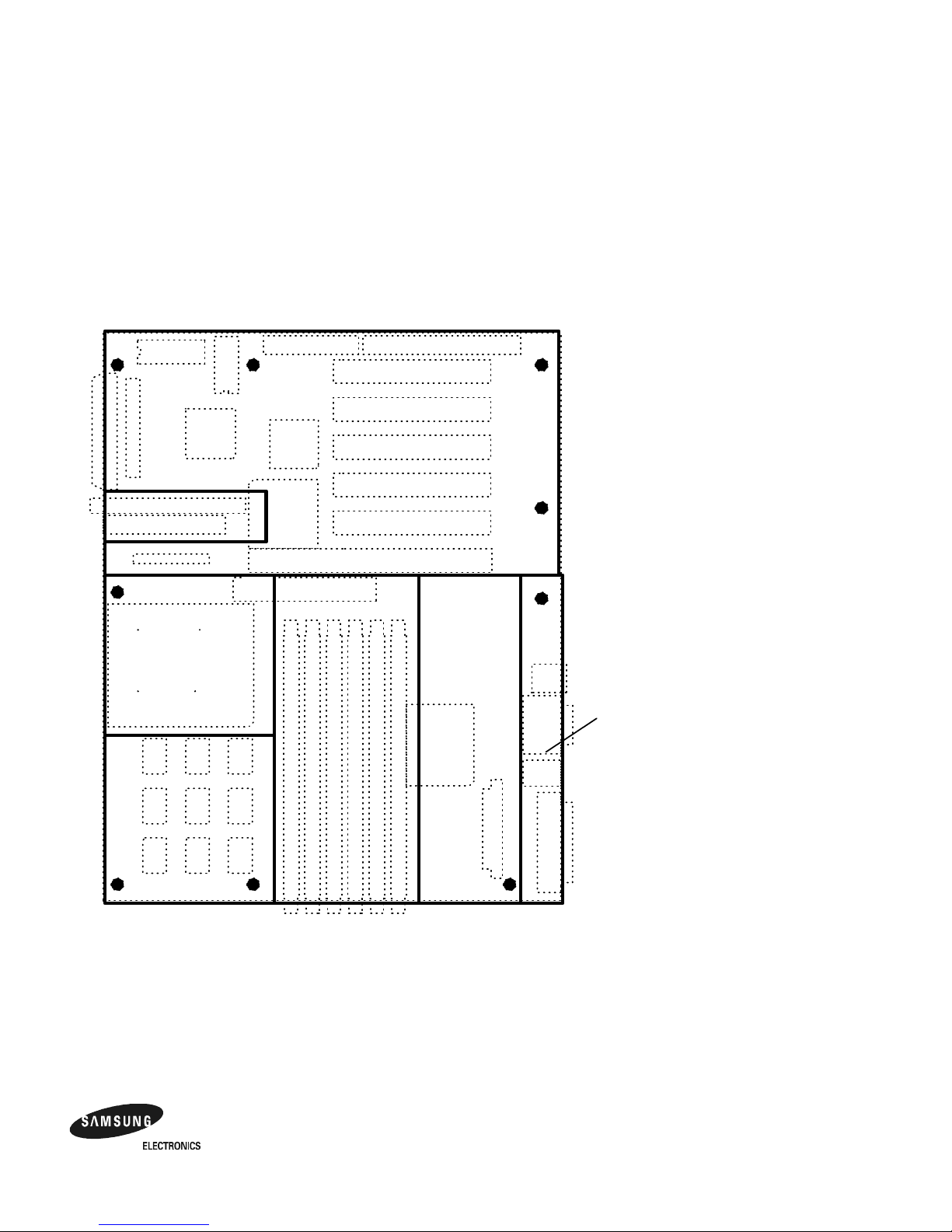
Table 2–1 provides an overview of the AlphaPC 164UX motherboard’s features.
Figure 2–1 shows the AlphaPC 164UX motherboard and its components.
Table 2–1 AlphaPC 164UX Features
Feature Description
Microprocessor Alpha 21164 microprocessor (64-bit RISC)
Core logic chip Digital Semiconducto r 21174 core logi c chip, comprising a single
control chip that provides an interface to system memory and the
PCI bus
Main memory 32MB to 3GB memory array –- Three banks of 128-bit memory;
168-pin unbuffered SDRAM DIMMs with ECC
Caching:
L1 Icache 8KB, direct-mapped instruc tion cache on the CPU chip
L1 Dcache 8KB, direct-mapped data cache on the CPU chip
L2 Scache 96KB, three-way, set-associative, write-back unified instruction
and data cache on the CPU chip
L3 backup cache Onboard 2MB/4MB, direct-mapped, synchronous SSRAM backup
cache with 128-bit data path
I/O and miscellaneous support 32-bit and 64-bit, 33-MHz PCI
One 64-bit and five 32-bit PCI expansion slots
One dedicated ISA expansi on slot
DEC 21052 PCI-to-PCI Bridge chip
Intel 82371SB PCI-to-ISA bridge chip
DEC 21143 10/100 Mb/s Ethernet LAN Controller
Symbios 53C875 Ultra wide SCSI Controller
SMC FDC37C666 co mbination controller chip provides control
for diskettes, two UARTs with modem control, parallel port
1MB flash ROM
Firmware Windows NT ARCSBIOS firmware

2–2 Features of the AlphaPC164UX Motherboard
Figure 2–1 AlphaPC 164UX Jumper/Connector Location
U5U6
U7U8
J24
J33
J22
J21
J7
J6
J5
J2
J13
J25
J12
J34
Pwr LED
IDE LED
SCSI LED
Pwr
Switch
Reset
Switch
GND
FOK
+12
Blk
wire
Yellow
wire
Red
wire
J10
U3U4
J18
J16
J15
J28
U55
J31
J23
J30
J29
J17
J36
J37
J35

Features of the AlphaPC164UX Motherboard 2–3
Table 2–2 AlphaPC 164UX Jumper/Connector List
Item
No. Description Item No. Description
J2 Full length 64 bit PCI slot U3 DIMM socket 0
J5 Half length 32 bit PCI slot U4 DIMM socket 1
J6 Full length 32 bit PCI slot U5 DIMM socket 2
J7 Full length 32 bit PCI slot U6 DIMM socket 3
J10 Full length ISA slot U7 DIMM socket 4
J12 Serial Port connector U8 DIMM socket 5
J13 Parallel port connector U55 Microprocessor socket(21164 Alpha)
J15 Ultra Fast and Wide SCSI Connector
J16 Narrow SCSI connector
J17 SCSI LED connector
J18 Power connector
J21 Full length 32 bit PCI slot
J22 Full length 32 bit PCI slot
J23 Speaker connector
J24 IDE drive connector
J25 Keyboard/Mouse connector
J28 Configuration jumpers
J29 IDE LED connector
J30 2 pin Power LED connect or
J31 5 pin Power LED connect or
J33 Floppy drive connector
J34 10/100 Mbit ethernet connector
J35 Microprocessor fan/fan sense connector
J36 Power switch connector
J37 Reset switch connector

2–4 Features of the AlphaPC164UX Motherboard
Power Requirements
2.1 Power Requirements
The AlphaPC 164UX motherboard requires a minimum of a 300 watt power supply.
The power supply must be ATX-compliant.
Caution: Fan sensor required. The 21164 microprocessor cooling fan must
have a built-in sensor that will drive a signal if the airflow stops. The
sensor is connected to the motherboard connector J35. When the signal
is generated, the speaker generates a tone..
2.2 Environmental Requirements
The 21164 microprocessor is cooled by a small fan blowing directly into the chip’s
heat sink. The AlphaPC 164UX motherboard is designed to run efficiently using
only this fan. Additional fans may be necessary depending upon cabinetry and the
requirements of add-in cards and disk drives.
The AlphaPC 164UX motherboard is specified to run within the environment listed
in T able 2–4.
Table 2–3 Power Supply DC Current Requirements
Voltage Current
+3.3Vdc,±5% 14 A
+5 Vdc,
±5% 25 A
-5 Vdc,
±5% 0.5 A
+12 Vdc,
±5% 10 A
-12 Vdc,
±5% 0.5 A
Table 2–4 AlphaPC 164UX Motherboard Environmental Requirements
Parameter Specification
Operating Temperature 10°C to 40°C (50°F to 104°F)
Storage Temperature -55°C to 125°C ( -67°F to 257°F)
Relative Humidity 10% to 90% with ma ximum wet bulb temperature 28°C
(82°F) and a minimum dew point 2°C (36°F)
Rate of (dry bulb) temperature
change
11°C/hour
±2°C/hour (20°F/hour ±4°F/hour)

Features of the AlphaPC164UX Motherboard 2–5
Physical Parameters
2.3 Physical Parameters
This section has two parts: the first illustrates the distances between the board
mounting holes and the edges of the board; the second shows the vertical clearances
required by the board components at all points within the border of the AlphaPC
164UX.
All holes and board measurements are compliant with the ATX 2.01 specification.
The AlphaPC 164UX exceeds the ATX height indications in two places. The first is
at the location of the 21164 (the 2.5’ region).The second is at the location of the
SCSI connectors(the 1.0’ region to the left of the second PCI slots).
The AlphaPC motherboard is an ATX-size printed wiring board (PWB) with the following dimensions:
• Length: 30.48 cm (12.0 in ( 0.0005 in)
• Width: 24.38 cm (9.6 in ( 0.0005 in)
• Height: 6.86 cm (2.7 in)
The board can be used in certain desktop and deskside systems that have adequate
clearance for the 21164 heat sink and its cooling fan. All ISA and PCI expansion
slots are usable in standard desktop or deskside enclosures.
2.3.1 Board Measurements and Hole Locations
Figure 2–2 shows the Board measurements and hole locations for the AlphaPC
164UX

2–6 Features of the AlphaPC164UX Motherboard
Physical Parameters
Figure 2–2 Board measurement and Hole Position Diagram
2.3.2 Vertical Clearance
Figure 2–3 shows the Board Vertical Clearance for the AlphaPC 164UX
B oard M easurement s and Hole Locat ion s
9.600"
.25 0"
.65 0"
3.1"
.40 0"
3.750"
5.550"
12.00"
.25 0"
1.300"
Features of the AlphaPC164UX Motherboard 2–7
Physical Parameters
Figure 2–3 Board Vertical Clearance Diagram
0.5"
1.0"
1.0"
0.5"
1.5"
2.5"
V ert ical Clea rance Requirem ent s
1.5"
2–8 Features of the AlphaPC164UX Motherboard
Physical Parameters
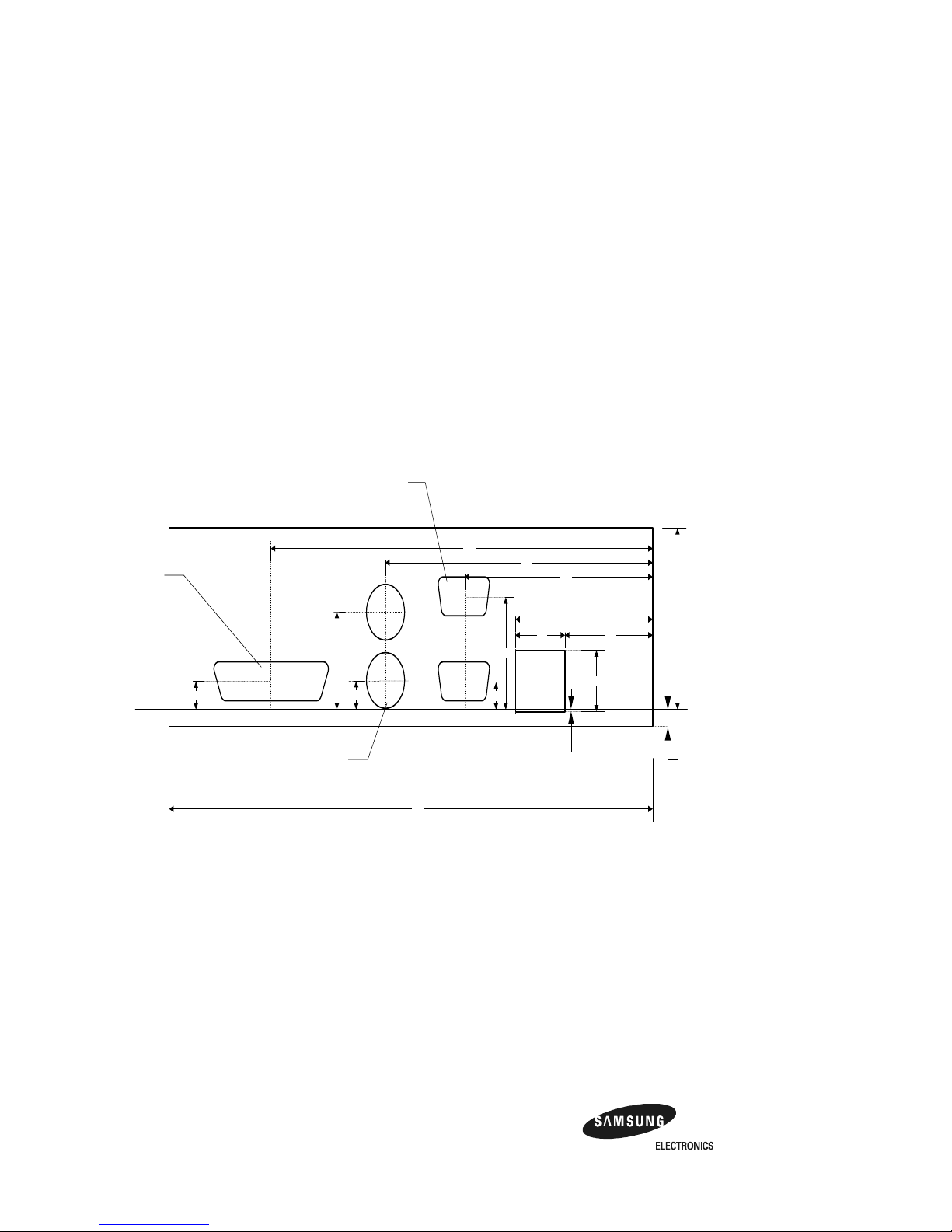
2.3.3 ATX Cutout Information
Figure 2–4 ATX Back Panel Dimension
In the event that an OEM or system integrator would like to use a chassis that supports a
n
standard ATX back-panel cutout, we have included the mechanical drawing used to create
standard cutout.
0.54
.020
.990
.240
.256
.856
.247
1.134
1.774
2.436
3.454
4.924
Standard 25 pin
DSUB connector
cutout with this center
point
Standard 9 pin DSUB
connector cutouts
with these center
points
Radius = .490 on both
circles. Dimensions
represent center of
circles.
.640
1.60
.150
6.250

AlphaPC 164UX Jumper Configura t ion 3–1
3
AlphaPC 164UX Jumper Configuration
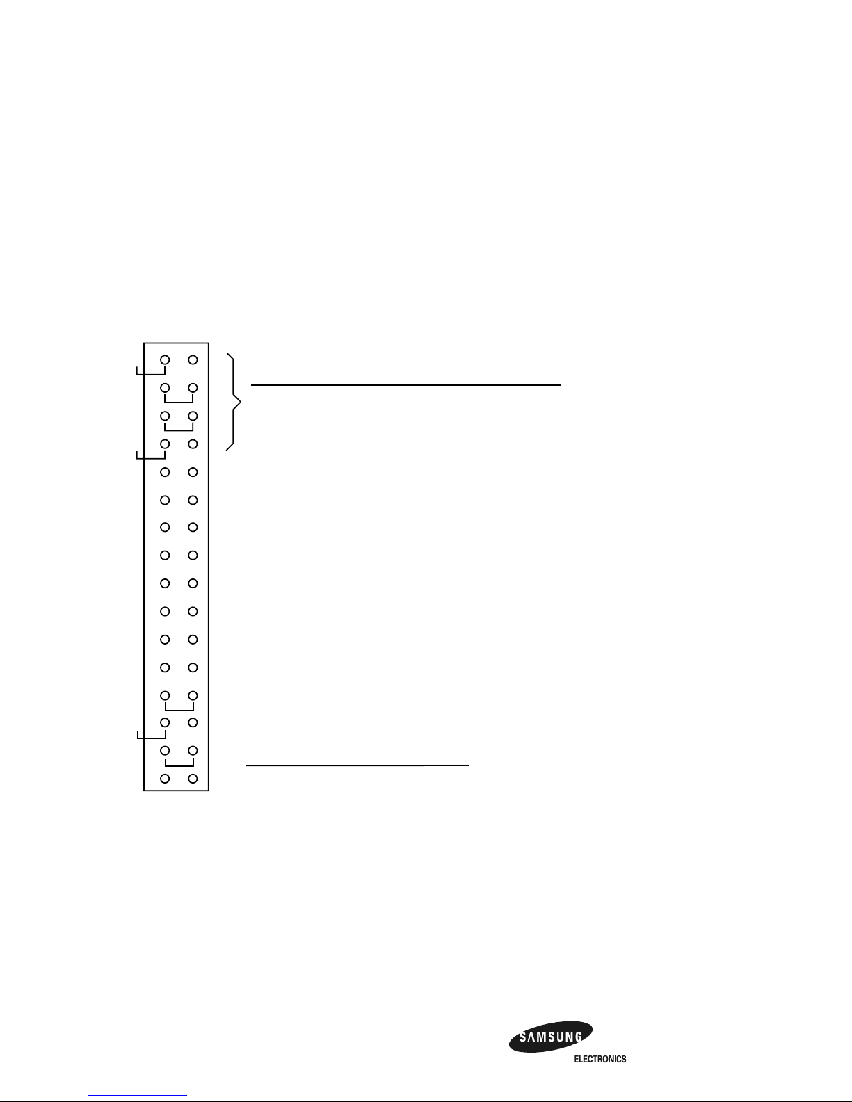
The AlphaPC 164UX has one set of jumpers located at J28. These jumpers set the
hardware configuration and boot options. Figure 2–1 shows the jumper location on
the AlphaPC 164UX motherboard. Figure 3–1 shows the jumper functions for each
group.
3–2 AlphaPC 164UX Jumper Configuration
CPU Speed Selection (Option 1,2,3, &4)
Figure 3–1 AlphaPC 164UX Configuration Jumpers
3.1 CPU Speed Selection (Option 1,2,3, &4)
The clock synthesizer makes it possible to change the frequency of the microproces-
sor’s clock input without having to change the clock crystal. Simply set the speed
jumpers to adjust the fre quency of the micro proces sor’ s cl ock. Thes e speed jumpe rs
are located at J2 8-1/2 (Opt ion 1), J28-3/4 ( Option 2), J28-5 /6 (Optio n 3), and J28-7/8
(Option 4). These four jumpers set speed at power-up as listed in Figure 3–1.
J28 System Configuration Jumpers
Option 5 : Pyxis Bus Speed Select(Default Out)
Option 6 : Reserved Default Out
Option 7 : Enable SROM Debug Mode(Default Out)
Option 8 : Enable Firmware Debug Mode(Default Out)
Option 9 : Enable only 1 set of Scache(Default Out)
Option 10 : Reserved Default Out
Option 11 : Boot SAFE ARCSBIOS Image(Default Out)
Option 12 : Reserved Default Out
Option 13 : Must be In
Frequency
300 MHz In In In In
In In In
Out In In
333 MHz
366 MHz
Out
In
Bcache Size
In
In
Out
Out
Option14 Option15
0MB
1MB
2MB
4MB
Out
In
Out
In
400 MHz Out Out In In
In Out In
In Out In
433 MHz
466 MHz
In
Out
500 MHz In Out Out In
Out Out In
In In Out
533 MHz
566 MHz
Out
In
600 MHz Out In In Out
Out In Out
Out In Out
633 MHz
666 MHz
In
Out
700 MHz In In Out Out
In Out Out
Out Out Out
733 MHz
766 MHz
Out
In
800 MHz Out Out Out Out
Option 1
Option 2
Option 3
Option 4
Option 5
Option 6
Option 7
Option 8
Option 9
Option 10
Option 11
Option 12
Option 13
Option 14
Option 15
Option 16
Option1 Option2 Option3 Option4
Option 16 : FAN OK Signal Do not ever populate(Default Out
)

AlphaPC 164UX Jumper Configura t ion 3–3
Bcache Size Jumpers (Option 14,15)
3.2 Bcache Size Jumpers (Option 14,15)
The Bcache size jumpers are located at J28–27/28 (Option14) and J28–29/30
(Option15), as shown in Figure 3–1. The AlphaPC 164UX-2/-4 is configured with
2MB/4MB of Bcache during production ; the other jumpers shown in Figure 3–1
(0,1) are for other implementations.
Note: The standard motherboard is manufactured with 128K X 18 or 256K X
18 data SSRAMs.
3.3 Boot Option Jumper (Option 11)
The boot option jumper is located at J28-21/22 (Option 11). The default position for
this jumper is out (Figure 3–1). This jumper sel ects the image to be loaded into memory from the system flash ROM. With the jumper out the ARCSBIOS firmware is
loaded. With the jumpe r in, the Safe ARCSBIOS is loaded.

AlphaPC 164UX Connector Pinouts 4–1
4
AlphaPC 164UX Connector Pinouts
This section lists the pinouts of all AlphaPC 164UX connectors. See Figure 2–1 for
connector locations.
4.1 PCI Bus Connector Pinouts
Table 4–1 shows the PCI bus connector pinouts.
Table 4–1 PCI Bus Connector Pinouts
(Sheet 1 of 2)
Pin Signal Pin Signal Pin Signal Pin Signal
32-Bit and 64-Bit PCI Connectors (J2, J5, J6, J7, J21, J22)
A1 TRST# A2 +12V A3 TMS A4 TDI
A5 Vdd A6 INTA A7 INTC A8 Vdd
A9 — A10 Vdd A11 — A12 Gnd
A13 Gnd A14 — A15 RST# A16 Vdd
A17 GNT# A18 Gnd A19 — A20 AD<30>
A21 +3V A22 AD<28> A23 AD<26> A24 Gnd
A25 AD<24> A26 IDSEL A27 +3V A28 AD<22>
A29 AD<20> A30 Gnd A31 AD<18> A32 AD<16>
A33 +3V A34 FRAME# A35 Gnd A36 TRDY#
A37 STOP# A38 STOP# A39 +3V A40 SDONE
A41 SBO# A42 Gnd A43 PAR A44 AD<15>
A45 +3V A46 AD<13> A47 AD<11> A48 Gnd
A49 AD<09> A50 Not used A51 Not used A52 C/BE#<0>
A53 +3V A54 AD<06> A55 AD<04> A56 Gnd
A57 AD<02> A58 AD<00> A59 Vdd A60 REQ64#
A61 Vdd A62 Vdd B1 –12V B2 TCK
B3 Gnd B4 TDO B5 Vdd B6 Vdd
B7 INTB B8 INTD B9 PRSNT1# B10 —
 Loading...