

Samsung DB98032978A, DB98032978A4, RJ100F5HX Series, AJ100FCJ5 Series Installation Manual
RJ100F5HX
www.keveklima.hu
AJ100FCJ5**
Air Conditioner
installation manual
**
imagine the possibilities
Thank you for purchasing this Samsung product.
To receive more complete service, please
register your product at
www.samsung.com/register
DB98-32978A(4)SE F I P D G
RJ100F5HXEA_IM_E_32978A(4).indd 31 2012-10-25 오후 5:22:56

Contents
General information
www.keveklima.hu
Safety precaution ..............................................................................................................................................................................................2
Accessories
Deciding on where to install the air conditioner
Space requirement for outdoor unit
Indoor/outdoor unit installation drawings
Refrigerant piping work
Important information regarding the refrigerant use
Charging additional refrigerant
Pump down operation
Method for connecting wires
Setting indoor unit address
Setting installation option
Installing transmitter and sub PCB for central control
How to use additional function
Test run and nal check
Troubleshooting
..........................................................................................................................................................................................................4
...............................................................................................................................5
.......................................................................................................................................................6
...........................................................................................................................................8
................................................................................................................................................................................. 9
...................................................................................................................11
...............................................................................................................................................................12
................................................................................................................................................................................12
...................................................................................................................................................................12
.......................................................................................................................................................................15
........................................................................................................................................................................ 22
................................................................................................................. 24
.............................................................................................................................................................. 26
.............................................................................................................................................................................. 27
.............................................................................................................................................................................................28
Safety precautions
(Carefully follow the precautions listed below because they are essential to guarantee the safety of the equipment.)
• Always disconnect the air conditioner from the power supply before servicing it or
WARNING
accessing its internal components.
Verify that installation and testing operations are performed by qualified personnel.
•
•
Verify that the air conditioner is not installed in an easily accessible area.
Carefully read the content of this manual before installing the air conditioner and store the manual in a safe place in
order to be able to use it as reference after installation.
For maximum safety, installers should always carefully read the following warnings.
Store the operation and installation manual in a safe location and remember to hand it over to the new owner if the
air conditioner is sold or transferred.
This manual explains how to install an indoor unit with a split system with two SAMSUNG units. The use of other types
of units with different control systems may damage the units and invalidate the warranty. The manufacturer shall not
be responsible for damages arising from the use of non compliant units.
The air conditioner is compliant with the requirements of the Low Voltage Directive (72/23/EEC), the EMC Directive
(89/336/EEC), and the Directive on pressurized equipment (97/23/EEC).
The manufacturer shall not be responsible for damage originating from unauthorized changes or the improper connection
of electric and hydraulic lines. Failure to comply with these instructions or to comply with the requirements set forth in the
“Operating limits” table, included in the manual, shall immediately invalidate the warranty.
The air conditioner should be used only for the applications for which it has been designed: the indoor unit is not
suitable to be installed in areas used for laundry.
Do not use the units if damaged. If problems occur, switch the unit off and disconnect it from the power supply.
2
RJ100F5HXEA_IM_E_32978A(4).indd 2 2012-10-25 오후 5:22:42

Safety precautions
General information
installinG the unit
Power suPPly line, fuse or circuit breaker
www.keveklima.hu
In order to prevent electric shocks, fires or injuries, always stop the unit, disable the protection switch and contact
SAMSUNG’s technical support if the unit produces smoke, if the power cable is hot or damaged or if the unit is very noisy.
Always remember to inspect the unit, electric connections, refrigerant tubes and protections regularly.
These operations should be performed by qualified personnel only.
The unit contains moving parts, which should always be kept out of the reach of children.
Do not attempt to repair, move, alter or reinstall the unit. If performed by unauthorized personnel, these operations
may cause electric shocks or fires.
Do not place containers with liquids or other objects on the unit.
All the materials used for the manufacture and packaging of the air conditioner are recyclable.
The packing material and exhaust batteries of the remote control(optional) must be disposed of in accordance with
current laws.
The air conditioner contains a refrigerant that has to be disposed of as special waste. At the end of its life cycle, the air
conditioner must be disposed of in authorized centers or returned to the retailer so that it can be disposed of correctly
and safely.
IMPORTANT: When installing the unit, always remember to connect first the refrigerant tubes, then the electrical lines.
Upon receipt, inspect the product to verify that it has not been damaged during transport. If the product appears
damaged, DO NOT INSTALL it and immediately report the damage to the carrier or retailer (if the installer or the
authorized technician has collected the material from the retailer.)
After completing the installation, always carry out a functional test and provide the instructions on how to operate
the air conditioner to the user.
Do not use the air conditioner in environments with hazardous substances or close to equipment that release free
flames to avoid the occurrence of fires, explosions or injuries.
To prevent injury when accidentally touching the indoor unit fan, install the indoor unit at least 2.5m above the floor.
The air conditioner should be used only for the applications for which it has been designed: the indoor unit is not
suitable to be installed in areas used for laundry.
Our units must be installed in compliance with the spaces indicated in the installation manual to ensure either
accessibility from both sides or ability to perform routine maintenance and repairs. The units’ components must be
accessible and that can be disassembled in conditions of complete safety either for people or things.
For this reason, where it is not observed as indicated into the Installation Manual, the cost necessary to reach and repair
the unit (in safety, as required by current regulations in force) with slings, trucks, scaffolding or any other means of
elevation won’t be considered in-warranty and charged to end user.
Always disassemble the electric lines before the refrigerant tubes.
ENGLISH
Always make sure that the power supply is compliant with current safety standards. Always install the air conditioner in
compliance with current local safety standards.
Always verify that a suitable grounding connection is available.
Verify that the voltage and frequency of the power supply comply with the specifications and that the installed power is
sufficient to ensure the operation of any other domestic appliance connected to the same electric lines.
Always verify that the cut-off and protection switches are suitably dimensioned.
Verify that the air conditioner is connected to the power supply in accordance with the instructions provided in the
wiring diagram included in the manual.
Always verify that electric connections (cable entry, section of leads, protections…) are compliant with the electric
specifications and with the instructions provided in the wiring scheme. Always verify that all connections comply with
the standards applicable to the installation of air conditioners.
3
RJ100F5HXEA_IM_E_32978A(4).indd 3 2012-10-25 오후 5:22:42

A
www.keveklima.hu
Accessories
The following accessories are supplied with the air conditioner.
Accessories in the outdoor unit case
3-wire
Power Cable
(option)
Flare Nuts, 15.88mm
outer pipe diameter
※ Attach Energy Label to the outdoor unit properly when installing.
≫
The 3-wire power cable and the 2-wire assembly cable are optional. If these cables are not supplied,
use the standard cable approved by IEC standard.
Please, check “Method for connecting wires” section.
2-wire
Assembly Cable
(option)
Flare Nuts, 9.52mm
outer pipe diameter
Drain Plug Installation Manual Rubber Leg
Tube connector
(Pipe 12.70mm;
Bolt 9.52mm)
Tube connector
(Pipe 12.70mm;
Bolt 15.88mm)
Energy Label
4
RJ100F5HXEA_IM_E_32978A(4).indd 4 2012-10-25 오후 5:22:42

A
www.keveklima.hu
Deciding on where to install the air conditioner
When deciding on the location of the air conditioner with the owner, the following restrictions must be taken
into account.
General
Do NOT install the air conditioner in a location where it will come into contact with the following elements :
◆ Combustible gases
◆ Saline air
◆ Machine oil
◆ Sulphide gas
◆ Special environmental conditions
◆ The air conditioner should be used only for the applications for which it has been designed : the indoor unit is not
suitable to be installed in areas used for laundry. If you must install the unit in such conditions, first consult your dealer.
Outdoor Unit
◆ The outdoor unit must NEVER be placed on its side or upside down, as the compressor lubrication oil will run into the cooling
circuit and seriously damage the unit.
◆ Choose a location that is dry and sunny, but not exposed to direct sunlight or strong winds.
◆ Do not block any passageways or thoroughfares.
◆ Choose a location where the noise of the air conditioner when running and the discharged air do not disturb any neighbours.
◆ Choose a position that enables the piping and cables to be easily connected to the indoor unit and the recommended
length will be respected.
◆ Install the outdoor unit on a flat, stable surface that can support its weight and does not generate any unnecessary
noise and vibration.
◆ Position the outdoor unit so that the air flow is directed towards the outside, as indicated by the arrows on the top of the unit.
◆ Maintain sufficient clearance around the outdoor unit, as indicated in page 8.
◆ Make sure that the water dripping from the drain hose runs away correctly and safely.
◆ You have just purchased a Free Joint Multi air conditioner and it has been installed by your installation specialist.
◆ This device must be installed according to the national electrical rules.
◆ Max input power & current is measured according to IEC standard and input power & current is measured
according to ISO standard.
◆
More than 2 indoor units should be installed when you use Free Joint Multi air conditioner.
◆ Our units must be installed in compliance with the spaces indicated in the installation manual to ensure either
accessibility from both sides or ability to perform routine maintenance and repairs.
The units’ components must be accessible and that can be disassembled in conditions of complete safety either for
people or things. For this reason, where it is not observed as indicated into the Installation Manual, the cost
necessary to reach and repair the unit (in safety, as required by current regulations in force) with slings, trucks,
scaffolding or any other means of elevation won’t be considered in-warranty and charged to end user.
◆
With an outdoor unit having net weight upper than 60kg, we suggest do not install it suspended on wall,
but considering floor standing one.
ENGLISH
5
RJ100F5HXEA_IM_E_32978A(4).indd 5 2012-10-25 오후 5:22:42
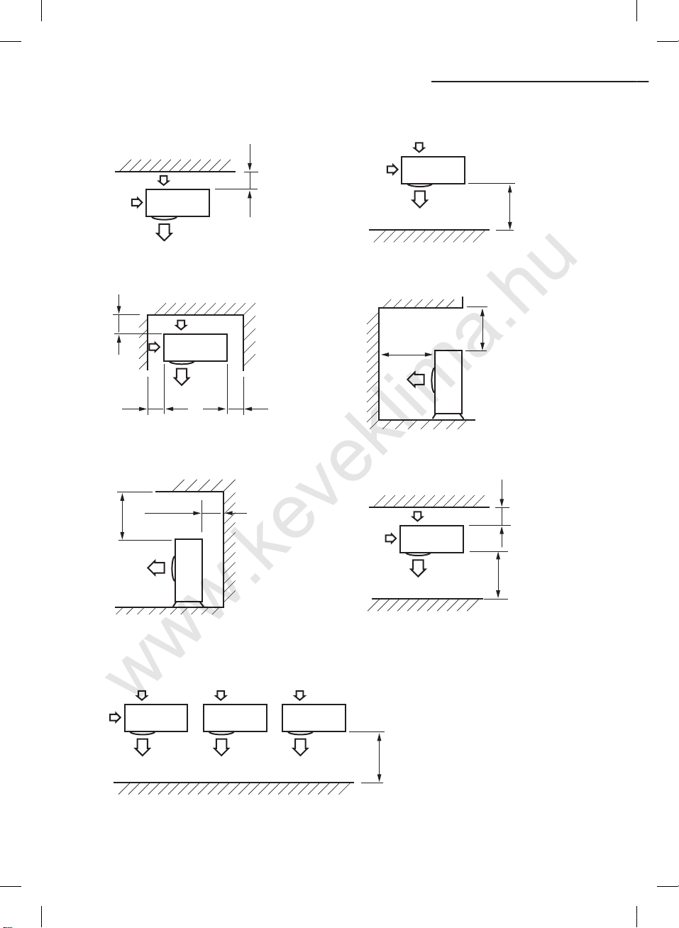
ASpace requirement for outdoor unit
www.keveklima.hu
When installing 1 outdoor unit
300 or more
※ When the air outlet is opposite the wall
300 or more
300 or more
※ When 3 sides of the outdoor unit are blocked
by the wall
300 or more
600 or more
600 or more
(Unit : mm)
1500 or more
※ When the air outlet is towards the wall
2000 or more
※ The upper part of the outdoor unit and the air
outlet is towards the wall
1500 or more
300 or more
1500 or more
※ The upper part of the outdoor unit and the
air outlet is opposite the wall
When installing more than 1 outdoor unit
When the air outlet is towards the wall
※
6
RJ100F5HXEA_IM_E_32978A(4).indd 6 2012-10-25 오후 5:22:42
※ When front and rear side of the outdoor unit is
towards the wall
(Unit : mm)
1500 or more
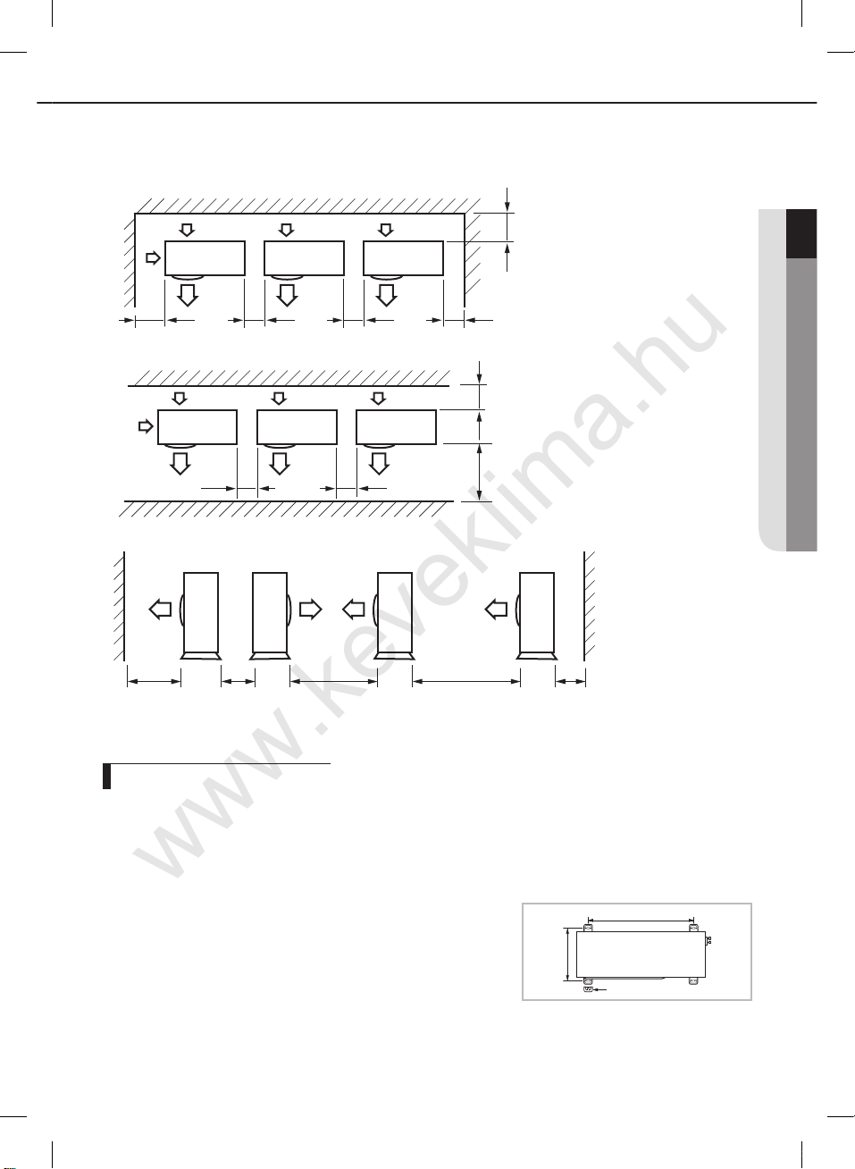
When installing more than 1 outdoor unit
www.keveklima.hu
(Unit : mm)
ENGLISH
300 or more
300 or more
※ When 3 sides of the outdoor unit are blocked by the wall
600 or more 600 or more
※ When front and rear side of the outdoor unit is towards the wall
1500 or more 600 or more 3000 or more
※ When front and rear side of the outdoor unit is towards the wall
600 or more 600 or more
3000 or more
600 or more
300 or more1500 or more
300 or more
Fixing the unit in position
The outdoor unit must be installed on a rigid and stable base to avoid any increase in the noise level and
vibration, particularly if the outdoor unit is to be installed close to a neighbour.
If it is to be installed in a location exposed to strong winds or at a height, the unit must be fixed to an
appropriate support (wall or ground).
1.
Position the outdoor unit so that the air flow is directed towards the
outside, as indicated by the arrows on the top of the unit.
2.
Attach the outdoor unit to the appropriate support using anchor bolts.
◆ The earthing wire for the telephone line cannot be used to earth the air
conditioner.
3.
If the outdoor unit is exposed to strong winds, install shield plates around
the outdoor unit, so that the fan can operate correctly.
≫
Certainly fix up its rubber leg in order to prevent its vibration and noise.
RJ100F5HXEA_IM_E_32978A(4).indd 7 2012-10-25 오후 5:22:42
360mm
620mm
Rubber leg
7
A
www.keveklima.hu
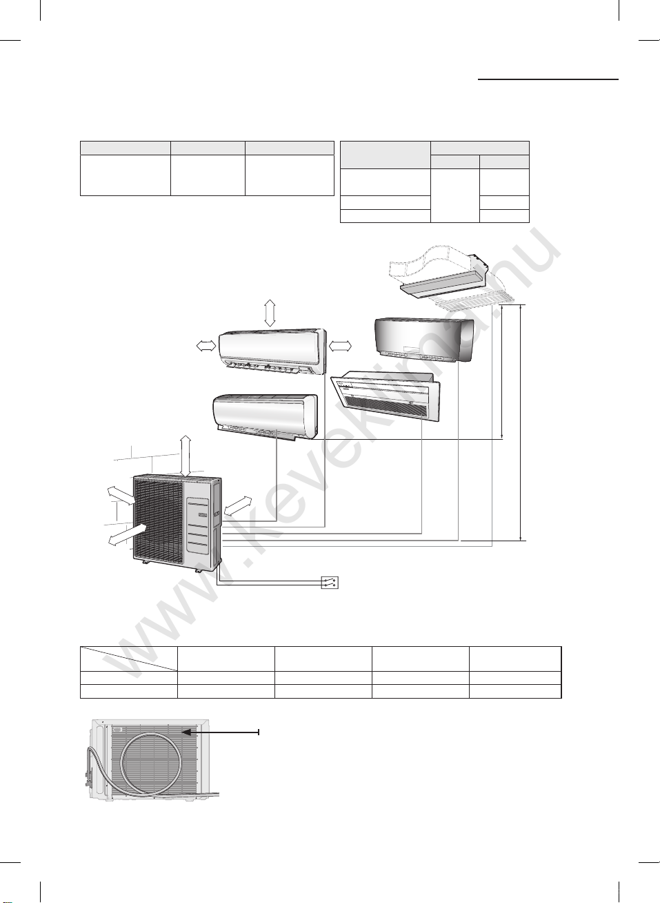
Indoor/outdoor unit installation drawings
◆ Piping outside diameter
Indoor unit Outdoor unit Power supply ø, V, Hz
020/023/026/
**
030/035/052/
07/09/12/18/24
**
RJ100F5HX
AJ100FCJ5
**
**
1,220-240,50/60
200 mm
or more
Unit
020/023/026/
**
030/035/07/09/12
052/18
**
**
**24**
Liquid Gas
**
Outside diameter
1/4"
3/8"
1/2"
5/8"
300 mm
minimum
600 mm
minimum
100 mm
or more
600 mm
minimum
300 mm
minimum
A CB D E
160 mm or more
Main power switch
◆ Piping length and the height
1 Room max
length
Dimension 25m 80m 15m 7.5m
Composition A, B, C, D, E A+B+C+D+E (H) (h)
5 Room total max
length
Make at least one round :
It will reduce noise and vibration
indoor unit & outdoor unit
Max height between
(h) (H)
Max height between
indoor units
※ The appearance of the unit may be different from the diagram depending on the model.
8
RJ100F5HXEA_IM_E_32978A(4).indd 8 2012-10-25 오후 5:22:43

A
www.keveklima.hu
Refrigerant piping work
Installing drain hose
While heating, ice may accumulate. During the process of
defrosting, check if condensation draining is adequate.
For adequate draining, do the following :
1.
Insert the drain plug into the drain hole on the underside of
the outdoor unit.
2.
Connect the drain hose to the drain plug.
3. Ensure that condensation draining is adequate.
Drain hole
Drain hole
Cutting/extending the piping
1. Make sure that you have the required tools available (pipe cutter, reamer,aring tool and pipe holder).
2. If you wish to shorten the piping, cut it using a pipe cutter, taking care to ensure that the cut edge remains at a
90° angle with the side of the pipe,and referring to the illustrations below for examples of edges cut correctlyand
incorrectly.
3. To prevent any gas from leaking out, remove all burrs at the cut end of the pipe, using a reamer.
4. Slide a are nut on to the pipe and modify the are.
Outer Diameter (D) Thickness Depth (A)
ø6.35 mm(1/4") 0.8mm 1.3 mm
ø9.52 mm(3/8") 0.8mm 1.8 mm
ø12.70 mm(1/2") 0.8mm 2.0 mm
ø15.88 mm(5/8") 0.8mm 2.2 mm
5. Check that the flaring is correct, referring to the illustrations below for examples of incorrect flaring.
Oblique Rough Burr
ENGLISH
InclinedCorrect
6. Align the pipes to be connected and tighten the are nuts rst manually and then with a torque wrench, applying the
following torque.
Outer Diameter (D) Thickness Torque (kgf·cm)
ø6.35 mm(1/4") 0.8mm 140~170
ø9.52 mm(3/8") 0.8mm 250~280
ø12.70 mm(1/2") 0.8mm 380~420
ø15.88 mm(5/8") 0.8mm 440~480
7. For further details on how to connect up to the outdoor unit and purge the circuit, refer to page 10.
In case welding the pipe, the gas nitrogen must be blown into the parts.
≫
RJ100F5HXEA_IM_E_32978A(4).indd 9 2012-10-25 오후 5:22:44
Surface
CrackedDamaged
Uneven
Thickness
9
A
www.keveklima.hu
Refrigerant piping work
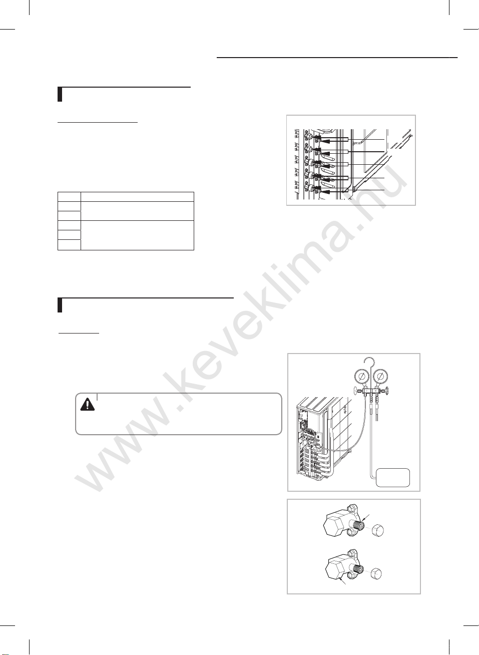
Connecting refrigerant pipe
RJ100F5HX** / AJ100FCJ5
Follow dierent orders depending on the capacity of indoor units.
016/020/023/026/030/035**/AQV07/09/12**/AR07/09/12
**
◆
Install pipes between indoor and outdoor units orderly as [A→B →C→D→E].
052**/AQV18/24**/AR18/24
**
Install pipes between indoor and outdoor units orderly as [ C→D→E].
◆
Port Indoor unit
A
020/023/026/030/035/07/09/12
**
B
C**020/023/026/030/035/07/09/12**
D
052/18
**
E
**24**
1) Use tube connector (pipe 12.70mm, bolt 9.52mm)
2) Use tube connector (pipe 12.70mm, bolt 15.88mm)
**
**
**
**
**
Purging air and checking gas leakage
Purging air
1 Check the piping connections.
2
Connect the charging hose of low pressure side of manifold gauge to the
packed valve having a service port (5/8” Packed valve) as shown at the
figure (Value stem: 1/2” - 20UNF).
Make the electrical connection and leave the system into “stand
◆
by mode”. Do not turn on the system! This is necessary for better
WARNING
vacuum operation (full OPEN position of Electronic Expansion
Valve - EEV -).
OUTDOOR UNIT
A unit
B unit
C unit
D unit
E unit
3 Open the valve of the low pressure side of manifold gauge
counter clockwise.
Purge the air from the system using vacuum pump for about 30 minutes.
4
- Close the valve of the low pressure side of manifold gauge clockwise.
- Make sure that pressure gauge show -0.1MPa(-76cmHg) after about
30 minutes. This procedure is very important in order to avoid gas leak.
- Turn off the vacuum pump.
- Remove the hose of the low pressure side of manifold gauge.
5 Set valve cork of both liquid side and gas side of packed valve to the
open position.
6 Mount the valve stem nuts and the service port cap to the valve, and
tighten them at the torque of 183kgf•cm with a torque wrench.
7 Check for gas leakage.
- At this time, especially check for gas leakage from the 3-way valve’s
stem nuts, and from the service port cap.
Service port
Vacuum
Pump
Valve stem
Stem cap
10
RJ100F5HXEA_IM_E_32978A(4).indd 10 2012-10-25 오후 5:22:44

Checking gas leakage
www.keveklima.hu
Before completing the installation (insulation of the cables, hose and piping and xing of the indoor unit to
the installation plate), you must check that there are no gas leaks.
LEAK TEST WITH NITROGEN (before opening valves)
In order to detect basic refrigerant leaks, before recreating the vacuum and
recirculating the R-410A, it’s responsible of installer to pressurize the whole system
with nitrogen (using a cylinder with pressure reducer) at a pressure above 30 bar
(gauge).
LEAK TEST WITH R-410A (after opening valves)
Before opening valves, discharge all the nitrogen into the system and create vacuum
according to page 10.
After opening valves, check leaks using a leak detector for refrigerant.
Important information regarding the refrigerant use
This product contains uorinated greenhouse gases covered by
the Kyoto Protocol. Do not vent gases into the atmosphere.
CAUTION :
Inform user if system contains 3 kg or more of fluorinated greenhouse gases.
In this case, it has to be checked for leakage at least once every 12 months, according to regulation N°842/2006. This activity has to be covered by qualified
personnel only.
In case situation above (3 kg or more of R-410A), installer (or recognised person
which has responsability for final check) has to provide a
maintenance book, with all the information recorded according to
REGULATION (EC) N°842/2006 OF THE EUROPEAN PARLIAMENT AND OF THE
COUNCIL of 17 May 2006 on certain fluorinated greenhouse gases.
Please ll in with indelible ink,
- ① the factory refrigerant charge of the product,
- ② the additional refrigerant amount charged in the eld and
the total refrigerant charge.
-
①+②
on the refrigerant charge label supplied with the product.
a. Factory refrigerant charge of the product: see unit name plate
b. Additional refrigerant amount charged in the field
( Refer to the above information for the quantity of
refrigerant replenishment.)
c. Total refrigerant charge
d. Refrigerant cylinder and manifold for charging
≫
The lled-out label must be adhered in the proximity of the product
charging port (e.g. onto the inside of the stop valve cover).
Refrigerant type GWP value
R410A 1975
GWP=Global Warming Potential
※
Contains uorinated greenhouse gases
covered by the Kyoto Protoco
Indoor unit
l.
d
a
= ( ) kg
= ( ) kg
b c
+
Outdoor unit
= ( ) kg
ENGLISH
11
RJ100F5HXEA_IM_E_32978A(4).indd 11 2012-10-25 오후 5:22:45
ACharging additional refrigerant
www.keveklima.hu
If you install the excessive length of pipe, add additional refrigerant as 20g per unit meter ;
refer to the table below.
Refer to the Service Manual for more details on this operation.
Model Total connecting pipe length (L) Adding refrigerant
RJ100F5HX
AJ100FCJ5
**
**
LT≤40m Chargeless
LT>40m (LT- 40m)x20g
APump down operation
PUMP DOWN (before disconnecing the refrigerant connections for unit
repair, removal or disposal)
Pump-down is an operation intended to collect all the system refrigerant in the outdoor
unit. This operation must be carried out before disconnecting the refrigerant pipe in
order to avoid refrigerant loss to the atmosphere.
1.
Shut off all the liquid valve with the Allen wrench.
2.
Turn the system on in cooling with fan operating at high velocity.
(Compressor will immediately start, provided 3 minutes have elapsed since the last
stop).
3.
After 2 minutes of operation, shut off the suction valves with the allen wrench.
4.
Turn the system off and switch mains supply off.
5.
Disconnect pipes. After disconnection, protect valves and tubing ends from dust.
6.
Compressor damage may occur if run at a negative suction pressure.
The designs and shape are subject to change according to the model.
※
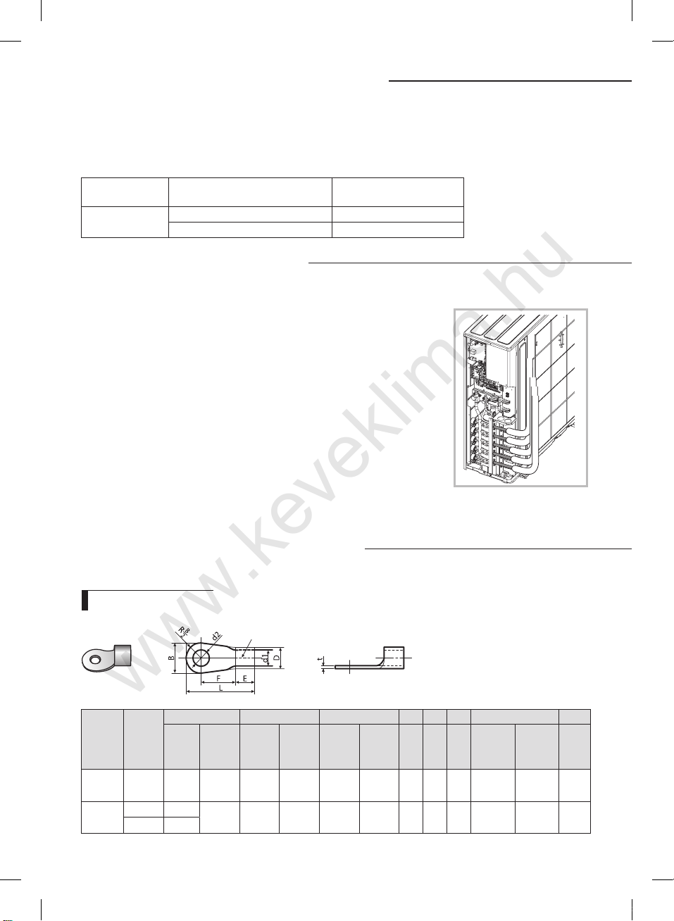
Method for connecting wires
Selecting wires size
Silver solder
Nominal
dimensions
12
RJ100F5HXEA_IM_E_32978A(4).indd 12 2012-10-25 오후 5:22:45
Nominal
dimensions
for cable
for screw
2
)
(mm
(mm)
0.75~1.5 4 6.6 ±0.2
4 8.5
4
4 9.5
B D d1 E F L d2 t
Standard
dimension
(mm)
Allowance
(mm)
±0.2
Standard
dimension
(mm)
3.4
5.6
Allowance
(mm)
+0.3
-0.2
+0.3
-0.2
Standard
Allowance
dimension
(mm)
1.7 ±0.2 4.1 6 16 4.3 ±0.20 0.7
3.4 ±0.2 6 5 20 4.3 ±0.20 0.9
(mm)
Min. Min. Max.
Standard
dimension
(mm)
Allowance
(mm)
Min.
A
1(L) 2(N)1(L) 2(N)
A B
1(L) 2(N) F1 F2 1(L) 2(N) F1 1(L) 2(N) F1 1(L) 2(N) F1F2
1
2
F1 F2 F1 F2
1
2
21
F2
1
2
F1 F2
F1 F2
F2
F1 F2
F1 F2
1
2
1 2
1
2
B
C B CB C B C
A
1(L) 2(N) F1 F2
F1 F2
F1 F2
1
2
B C
1(L) 2(N)1(L) 2(N)
1(L) 2(N)
F1 F2 F1 F2
F1 F2 F1 F2
L N
1 2
21
21
C
B
D
Earth
terminal
Earth
terminal
Earth
terminal
Earth
terminal
Earth
terminal
Earth
terminal
Earth
terminal
Earth
terminal
Earth
terminal
Earth
terminal
www.keveklima.hu
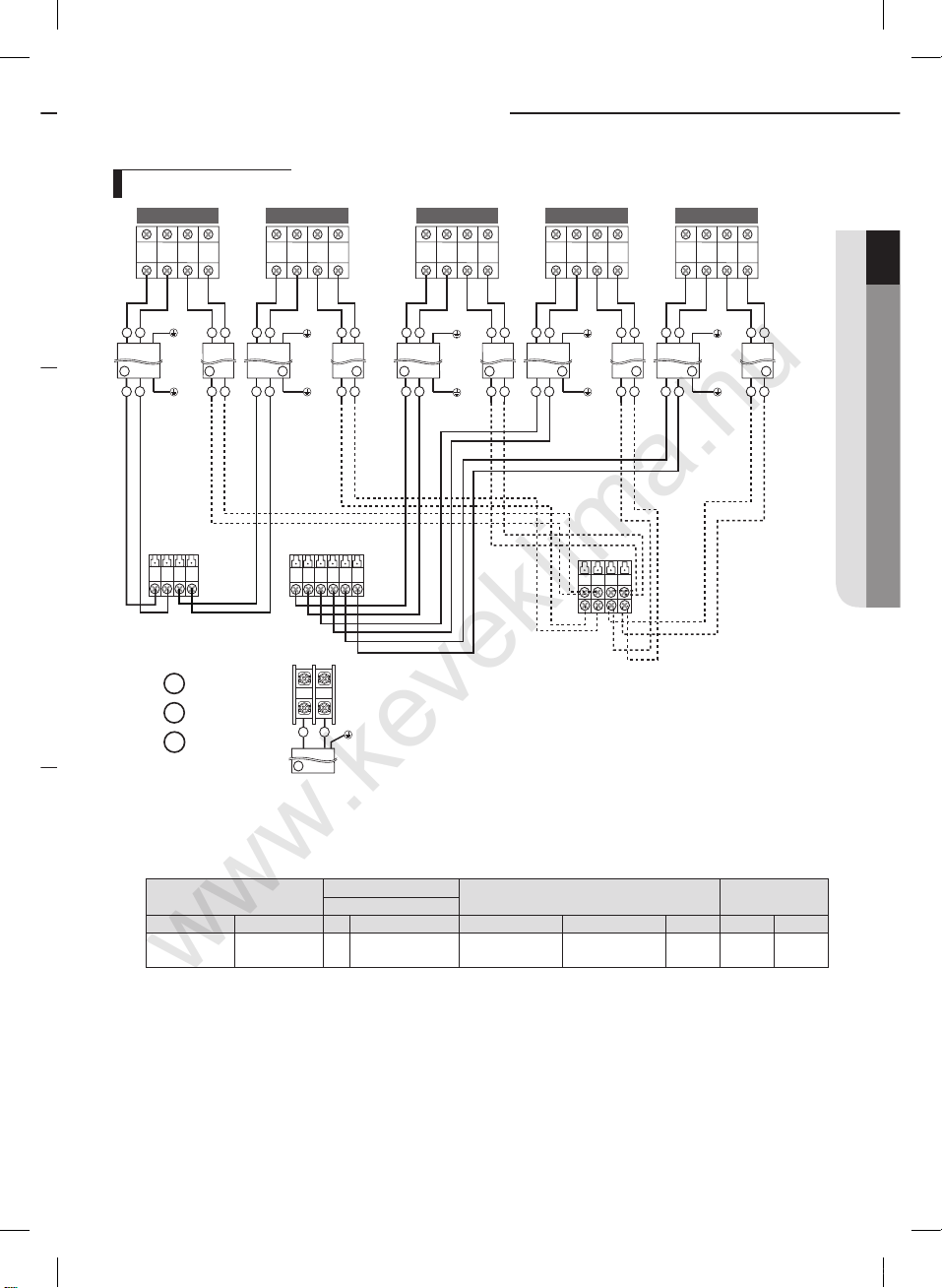
Method for connecting wires
Connecting wires
A-unit B-unit C-unit D-unit
Power cable to indoor units
A
B
C
Specification for circuit breaker and power supply cord
≫ Power supply cord is not supplied with air conditioner.
≫ Select the power supply cord in accordance with relevant local and national regulations.
≫ Wire size must comply with the applicable local and national code.
≫ Specifications for local wiring power supply cord and branch wiring are in compliance with local cord.
Outdoor Unit Indoor Unit Hz Volts Outdoor Indoor(Max.) Total MCA MFA
RJ100F5HX
AJ100FCJ5
Notes
1. Power supply cords of parts of appliances for outdoor use shall not be lighter than polychloroprene sheathed
flexible cord. (Code designation IEC:60245 IEC 57 / CENELEC:H05RN-F)
2. Select power supply cord based on MCA.
3. MFA is used to select the circuit breaker and the ground fault circuit interrupter (earth leakage circuit breaker).
4. MCA represents maximum input current.
5. MFA represents capacity which may accept MCA.
6. Communication Cable Specification: 2G. 0.75mm2 or more.
Abbreviations
- MCA : Min. Circuit Amps. (A)
- MFA : Max. Fuse Amps. (A)
Cable Type : A
Cable Type : B
Cable Type : C
Model
**
**
E-unit
Indoor unit
Assembly cable
Outdoor unit
Communication cable
to indoor units
Main Power
Supply cable
Earth
terminal
Outdoor Units
Rated
5 ROOM 50 1phase, 220-240 23.0 3.2 26.2 26.2 28.8
Maximun Input Current [A] Power Supply
ENGLISH
13
RJ100F5HXEA_IM_E_32978A(4).indd 13 2012-10-25 오후 5:22:45
Tightening power terminal
www.keveklima.hu
≫ Connect the cables to the terminal board using the compressed ring terminal.
≫ Use rated cables only.
≫ Connect the cables with driver and wrench that can apply the rated torque to the screws.
≫ Make sure that appropriate tightening torque is applied for cable connection. If the terminal is loose, arc heat may
occur and cause fire and if the terminal is connected too firmly, terminal may get damaged.
Screw Tighten Torque(kgf • cm) Position
M4 12.0~15.0 1(L), 2(N), L, N, F1, F2
Method for connecting wires
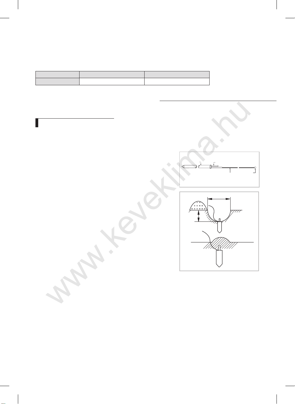
Checking correct earthing
If the power distribution circuit does not have an earth or the earth does not comply with specifications, an
earthing electrode must be installed. The corresponding accessories are not supplied with the air conditioner.
1.
Select an earthing electrode that complies with the specifications
given in the illustration opposite.
Determine a suitable location for the earthing electrode :
2.
◆ In damp hard soil rather than loose sandy or gravel soil that has a
higher earthing resistance.
◆ Away from underground structures or facilities, such as gas pipes,
water pipes, telephone lines and underground cables.
◆ At least two meters away from a lightening conductor earthing
electrode and its cable.
≫ The earthing wire for the telephone line cannot be used to earth the
air conditioner.
3.
Dig a hole of the size indicated in the illustration opposite, drive the
earthing electrode into position and cover the top of the electrode with
the excavated soil.
4.
Install a green/yellow insulated earthing wire (Ø1.6 mm, section 2 mm² or
greater) :
◆ If the earthing wire is too short, connect an extension lead, soldering
the connection and wrapping it with insulating tape (Do not bury the
soldered connection.)
◆ Secure the earthing wire in position with staples. If the earthing
electrode is installed in an area of heavy traffic, its wire must be
connected securely.j
5.
Carefully check the installation, by measuring the earthing resistance
with an earthing resistance tester. If the resistance is above the required
level(Example:100Ω), drive the earthing electrode deeper into the ground
or increase the number of earthing electrodes.
6.
Connect the earthing wire to the earthing screw on the air conditioner.
Carbon
plastic
PVC-insulated green
/yellow wire, 2mm² x 3.5 m
30 cm
Steel core
50 cm
To earthing
screw
14
RJ100F5HXEA_IM_E_32978A(4).indd 14 2012-10-25 오후 5:22:45
 Loading...