

Samsung AJ040MCJ2EH, AJ050MCJ2EH, AJ052MCJ3EH, AJ068MCJ3EH, AJ070MCJ4EH Installation Manual
...
Air conditioner
Installation manual
AJ∗∗∗MCJ∗EH
• Thank you for purchasing this Samsung air conditioner.
• Before operating this unit, please read this manual carefully and retain it for future
reference.

2
English
Contents
For information on Samsung’s environmental commitments and product specific regulatory obligations e.g. REACH
visit: samsung.com/uk/aboutsamsung/samsungelectronics/corporatecitizenship/data_corner.html
Safety Information 3
General information 3
Installing the unit 4
Power supply line, fuse or circuit breaker 4
Installation Procedure 5
Step 1 Choosing the installation location 5
Step 2 Checking and preparing accessories and tools 7
Step 3 Fixing the outdoor unit in place 7
Step 4 Connecting the power cables, communication cable, and controllers 8
Step 5 Optional: Extending the power cable 14
Step 6 Connecting the refrigerant pipe 16
Step 7 Optional: Cutting and flaring the pipes 17
Step 8 Connecting up and removing air in the circuit 18
Step 9 Performing the gas leak test 19
Step 10 Adding refrigent (R-410A) 19
Step 11 Connecting the drain hose to the outdoor unit 21
Step 12 Checking the earthing 21
Step 13 Setting an indoor unit address and installation option 22
Step 14 Cool and Heat modes operation test 30
Extra procedures 31
Pumping down refrigerant 31
Relocating the indoor and outdoor units 31
Using the stop valve 32
Appendix 33
Troubleshooting 33

3
English
Safety Information
WARNING
• Hazards or unsafe practices that may result in severe
personal injury or death.
CAUTION
• Hazards or unsafe practices that may result in minor
personal injury or property damage.
Carefully follow the precautions listed below because they
are essential to guarantee the safety of the equipment.
WARNING
• Always disconnect the air conditioner from the power
supply before servicing it or accessing its internal
components.
• Verify that installation and testing operations are
performed by qualified personnel.
• Verify that the air conditioner is not installed in an
easily accessible area.
General information
WARNING
• Carefully read the content of this manual before
installing the air conditioner and store the manual in
a safe place in order to be able to use it as reference
after installation.
• For maximum safety, installers should always carefully
read the following warnings.
• Store the operation and installation manual in a safe
location and remember to hand it over to the new
owner if the air conditioner is sold or transferred.
• This manual explains how to install an indoor unit with
a split system with two SAMSUNG units. The use of
other types of units with different control systems may
damage the units and invalidate the warranty. The
manufacturer shall not be responsible for damages
arising from the use of non compliant units.
• The manufacturer shall not be responsible for damage
originating from unauthorized changes or the
improper connection of electric and requirements set
forth in the “Operating limits” table, included in the
manual, shall immediately invalidate the warranty.
• The air conditioner should be used only for the
applications for which it has been designed: the indoor
unit is not suitable to be installed in areas used for
laundry.
• Do not use the units if damaged. If problems occur,
switch the unit off and disconnect it from the power
supply.
• In order to prevent electric shocks, fires or injuries,
always stop the unit, disable the protection switch
and contact SAMSUNG’s technical support if the unit
produces smoke, if the power cable is hot or damaged
or if the unit is very noisy.
• Always remember to inspect the unit, electric
connections, refrigerant tubes and protections
regularly. These operations should be performed by
qualified personnel only.
• The unit contains moving parts, which should always
be kept out of the reach of children.
• Do not attempt to repair, move, alter or reinstall the
unit. If performed by unauthorized personnel, these
operations may cause electric shocks or fires.
• Do not place containers with liquids or other objects
on the unit.
• All the materials used for the manufacture and
packaging of the air conditioner are recyclable.
• The packing material and exhaust batteries of the
remote controller(optional) must be disposed of in
accordance with current laws.
• The air conditioner contains a refrigerant that has
to be disposed of as special waste. At the end of its
life cycle, the air conditioner must be disposed of in
authorized centres or returned to the retailer so that it
can be disposed of correctly and safely.
• This appliance is not intended for use by persons
(including children) with reduced physical, sensory
or mental capabilities, or lack of experience and
knowledge, unless they have been given supervision
or instruction concerning use of the appliance by a
person responsible for their safety. Children should be
supervised to ensure that they do not play with the
appliance.
Safety Information

4
Contents
English
Safety Information
• For use in Europe: This appliance can be used by
children aged from 8 years and above and persons
with reduced physical, sensory or mental capabilities
or lack of experience and knowledge if they have been
given supervision or instruction concerning use of the
appliance in a safe way and understand the hazards
involved. Children shall not play with the appliance.
Cleaning and user maintenance shall not be made by
children without supervision.
Installing the unit
WARNING
IMPORTANT: When installing the unit, always remember
to connect first the refrigerant tubes, then the electrical
lines.
• Upon receipt, inspect the product to verify that
it has not been damaged during transport. If the
product appears damaged, DO NOT INSTALL it and
immediately report the damage to the carrier or
retailer (if the installer or the authorized technician has
collected the material from the retailer.)
• After completing the installation, always carry out a
functional test and provide the instructions on how to
operate the air conditioner to the user.
• Do not use the air conditioner in environments with
hazardous substances or close to equipment that
release free flames to avoid the occurrence of fires,
explosions or injuries.
• Our units should be installed in compliance with the
spaces shown in the installation manual, to ensure
accessibility from both sides and allow repairs or
maintenance operations to be carried out. The
unit’s components should be accessible and easy to
disassemble without endangering people and objects.
• For this reason, when provisions of the installation
manual are not complied with, the cost required to
access and repair the units (in SAFETY CONDITIONS,
as set out in prevailing regulations) with harnesses,
ladders, scaffolding or any other elevation system will
NOT be considered part of the warranty and will be
charged to the end customer.
Power supply line, fuse or circuit breaker
WARNING
• Always make sure that the power supply is compliant
with current safety standards. Always install the air
conditioner in compliance with current local safety
standards.
• Always verify that a suitable earthing connection is
available.
• Verify that the voltage and frequency of the power
supply comply with the specifications and that the
installed power is sufficient to ensure the operation of
any other domestic appliance connected to the same
electric lines.
• Always verify that the cut-off and protection switches
are suitably dimensioned.
• Verify that the air conditioner is connected to the
power supply in accordance with the instructions
provided in the wiring diagram included in the manual.
• Always verify that electric connections (cable entry,
section of leads, protections…) are compliant with
the electric specifications and with the instructions
provided in the wiring scheme. Always verify that all
connections comply with the standards applicable to
the installation of air conditioners.
• Devices disconnected from the power supply should
be completely disconnected in the condition of
overvoltage category.
• Be sure not to perform power cable modification,
extension wiring, and multiple wire connection.
‐ It may cause electric shock or fire due to poor
connection, poor insulation, or current limit
override.
‐ When extension wiring is required due to power
line damage, refer to "Step 5 Optional: Extending
the power cable" in the installation manual.
5
English
Installation Procedure
Installation Procedure
Step 1 Choosing the installation location
Installation location requirements
• Do not place the outdoor unit on its side or upside
down. Failing to do so may cause the compressor
lubrication oil to run into the cooling circuit and lead
to a serious damage to the unit.
• Install the unit in a well-ventilated location away from
direct sunlight or strong winds.
• Install the unit in a location that would not obstruct
any passageways or thoroughfares.
• Install the unit in a location that would not inconvenience
or disturb your neighbors, as they could be affected by
the noise or the airflow coming from the unit.
• Install the unit in a location where the pipes and the
cables can be easily connected to the indoor unit.
• Install the unit on a flat, stable surface that can
withstand the weight of the unit. Otherwise, the unit
can generate noise and vibration during operation.
• Install the unit so that the air flow is directed towards
the open area.
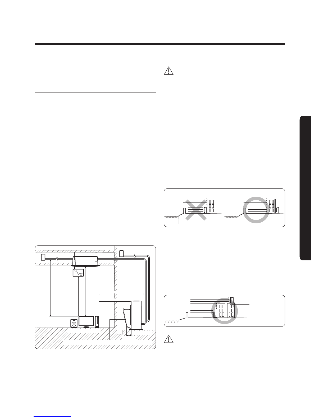
• Maintain sufficient clearance around the outdoor unit,
especially from a radio, computer, stereo system, etc.
Fuse
Fuse
Control
1.5 m or more
1 m or more
1 m or more
1.5 m or more
1.5 m or more
300 mm
Stereo
Computer
etc
Outdoor Unit
200 mm
Air Guide Duct (This product is not provided by Samsung)
Indoor Unit
• Install the unit at a height where its base can be firmly
fixed in place.
• Make sure that the water dripping from the drain hose
runs away correctly and safely.
CAUTION
• You have just purchased a system air conditioner and
it has been installed by your installation specialist.
• This device must be installed according to the
national electrical rules.
• If your outdoor unit exceeds a net weight of 60 kg,
do not install it on a suspended wall, but stand it
on a floor.
• When installing the outdoor unit at the seaside, make
sure that it is not directly exposed to sea breeze. If
you cannot find an adequate place free from direct
sea breeze, construct a protection wall or a protective
fence.
‐ Install the outdoor unit in a place (such as near
buildings etc.) where it can be prevented from sea
breeze. Failure to do so may cause a damage to the
outdoor unit.
Sea breeze Sea breeze
Sea
Sea
Outdoor Unit Outdoor Unit
• If you cannot avoid installing the outdoor unit at the
seaside, construct a protection wall around to block
the sea breeze.
• Construct a protection wall with a solid material such
as concrete to block the sea breeze. Make sure that the
height and the width of the wall are 1.5 times larger
than the size of the outdoor unit. Also, secure a space
larger than 700 mm between the protection wall and
the outdoor unit for exhausted air to ventilate.
Protection wall
Outdoor Unit
Sea breeze
Sea
CAUTION
• Depending on the condition of power supply, unstable
power or voltage may cause malfunction of the parts
or control system. (At the ship or places using power
supply from electric generator...etc)
6
Installation Procedure
English
Installation Procedure
• Install the unit in a place where water can drain
smoothly.
• If you have any difficulty finding installation location
as prescribed above, contact your manufacturer for
details.
• Be sure to clean the sea water and the dust on the
heat exchanger of the outdoor unit and apply a
corrosion inhibitor on it. (At least once in a year.)
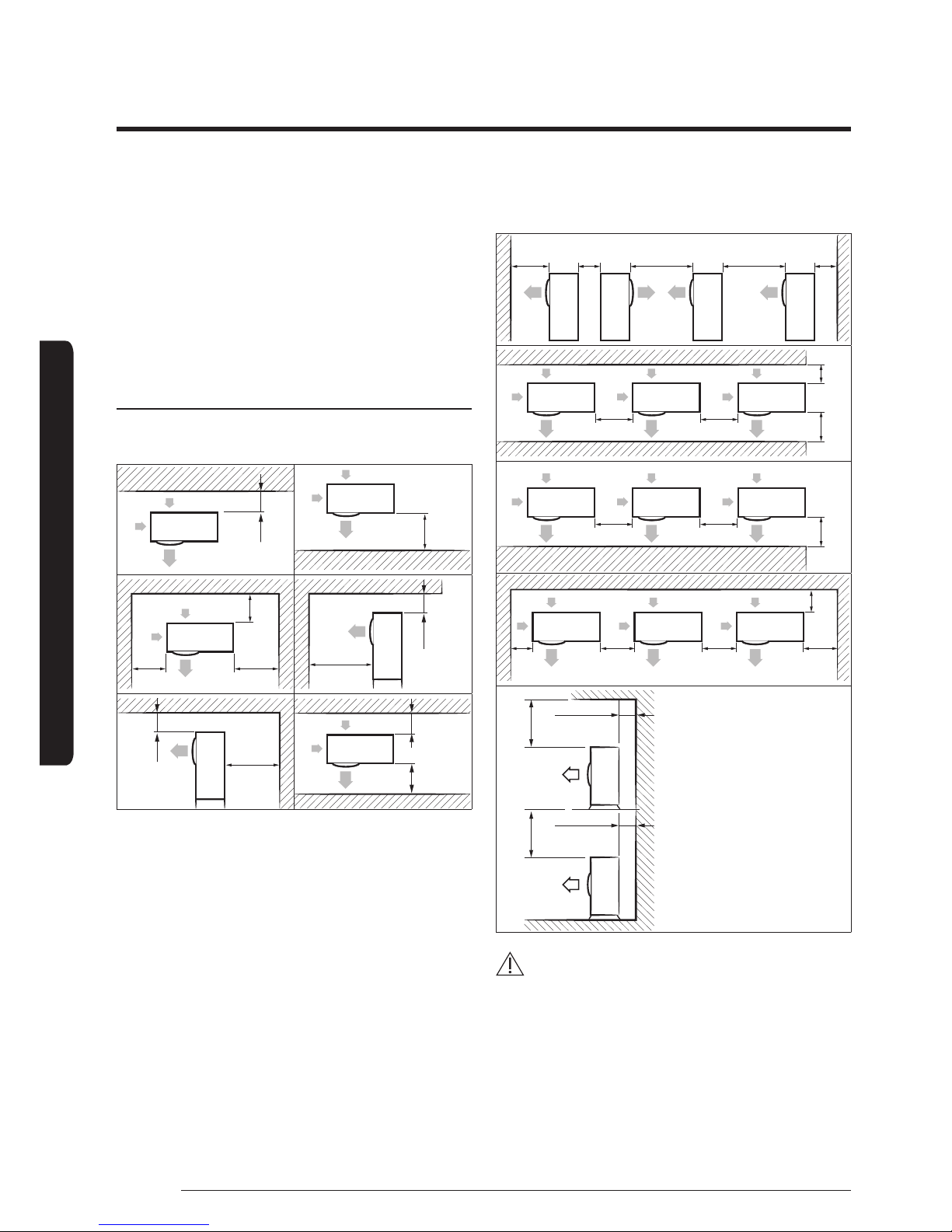
Minimum clearances for the outdoor unit
When installing 1 outdoor unit
(Unit: mm)
300 or more
1500 or more
300 or
more
600 or
more
300 or
more
2000 or
more
1500 or
more
600 or
more
300
or more
1500
or more
300 or
more
When installing more than 1 outdoor unit
(Unit: mm)
1500
or more
600
or more
3000
or more
3000
or more
300
or more
600
or more
600
or more
1500 or
more
300
or more
1500 or more
600
or more
600
or more
300
or more
600
or more
600
or more
600
or more
300
or more
300 or more
300 or more
500 or more 500 or more
CAUTION
• The outdoor unit must be installed according to the
specified distances in order to permit accessibility
from each side, to guarantee correct operation,
maintenance, and repair of the unit.
The components of the outdoor unit must be
reachable and removable under safe conditions for
people and the unit.
7
English
Installation Procedure
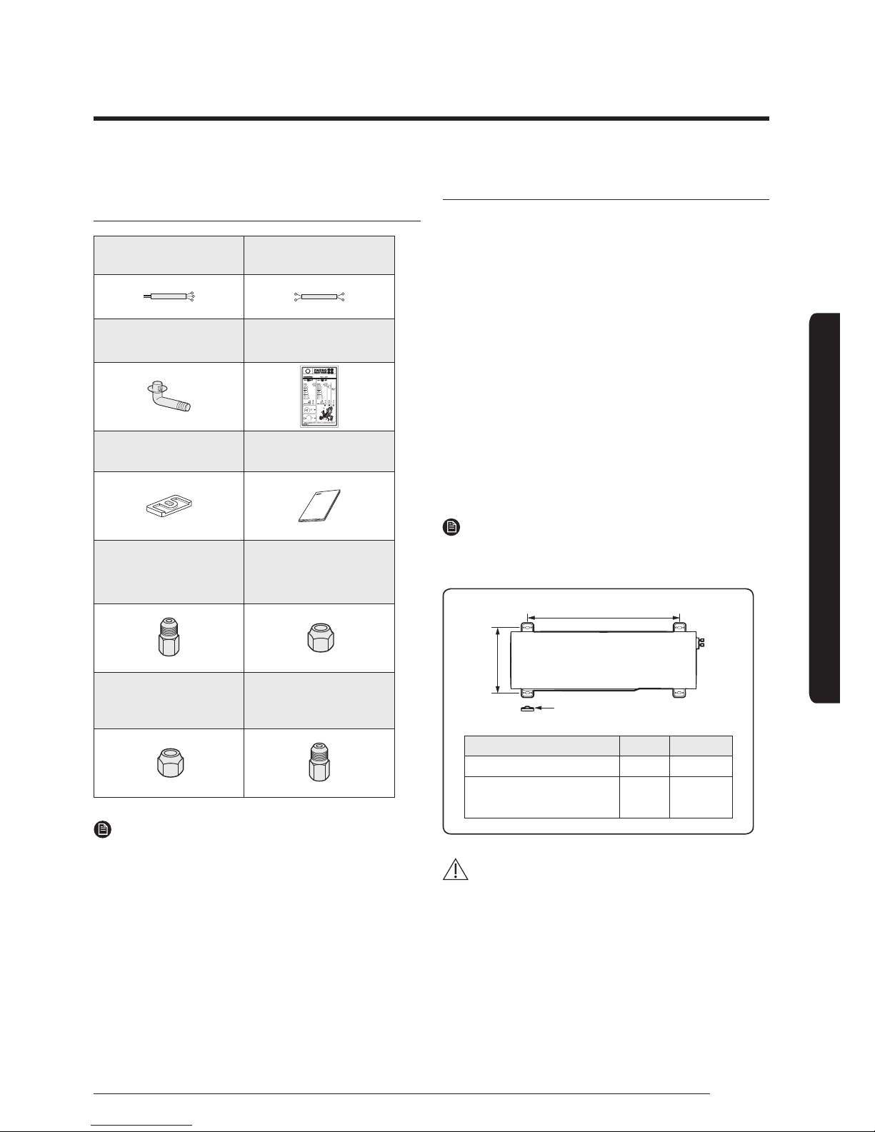
Step 2 Checking and preparing
accessories and tools
3-wire
Power Cable (option)
2-wire
Assembly Cable (option)
Drain Plug Energy Label
Rubber Leg Installation Manual
Flare Bolt
(Nut 12.70mm;Bolt
9.52mm)
(except AJ040MCJ2EH)
Flare Nuts, 9.52mm
outer pipe diameter
(except AJ040MCJ2EH)
Flare Nuts, 15.88mm
outer pipe diameter
(AJ080MCJ4EH)
Flare Bolt
(Nut 12.70mm; Bolt
15.88mm)(AJ080MCJ4EH)
NOTE
• Attach Energy Label to the outdoor unit properly when
installing.
• Wire assembly cables are optional. If they are not
supplied, use standard cables.
• The drain plug and the rubber legs are included only
when the air conditioner is supplied without assembly
pipes.
• If these accessories are supplied, they are in the
accessory package or outdoor unit package.
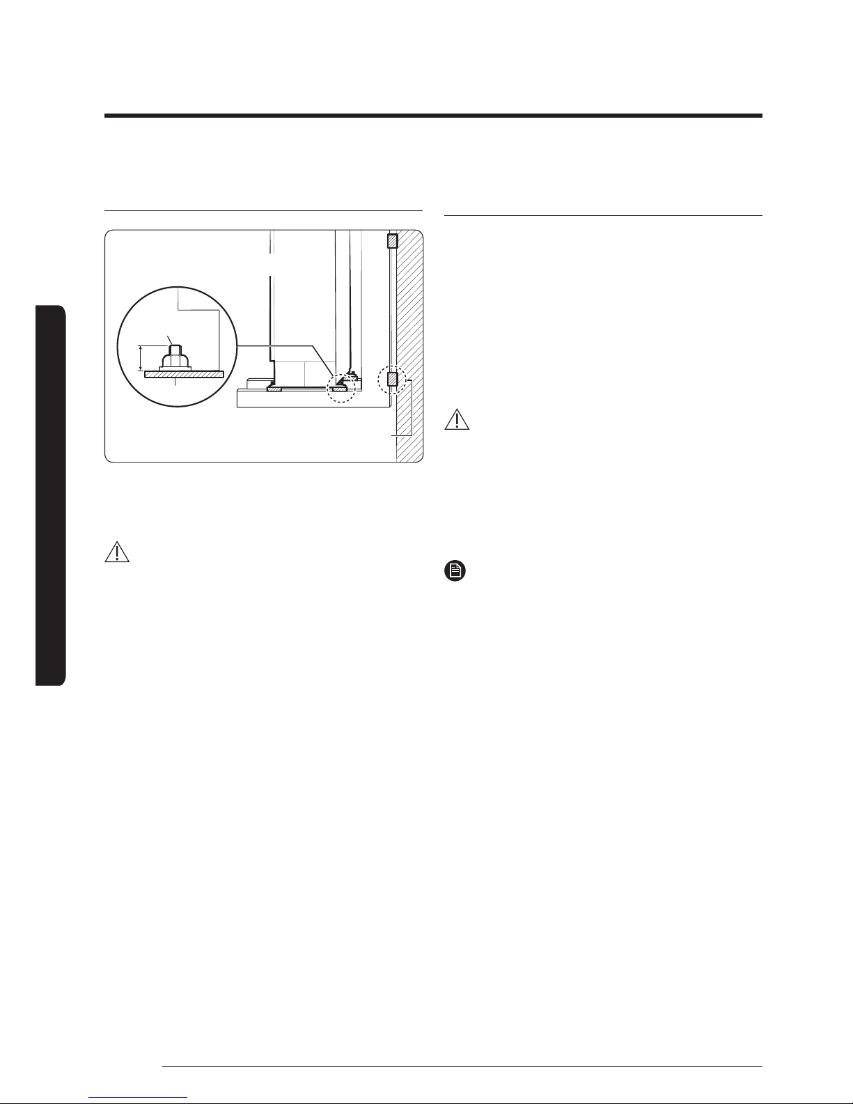
Step 3 Fixing the outdoor unit in place
Install the outdoor unit on a rigid and stable base to
prevent disturbance from any noise caused by vibration.
When installing the unit at a height or in a location
exposed to strong winds, fix the unit securely to a support
(i.e., a wall or a ground).
1 Position the outdoor unit so that the air flow is directed
towards the outside, as indicated by the arrows on the
top of the unit.
2 Attach the outdoor unit to the appropriate support
using anchor bolts.
• The earthing wire for the telephone line cannot be
used to earth the air conditioner.
3 DIf the outdoor unit is exposed to strong winds, install
shield plates around the outdoor unit, so that the fan
can operate correctly.
NOTE
• Certainly fix up its rubber leg in order to prevent its
vibration and noise.
X
Y
(Unit : mm)
Model X Y
AJ040/050MCJ2EH 612 317
AJ052/068MCJ3EH
AJ070/080MCJ4EH
660 340
CAUTION
• Install a drain outlet at the lowest end around the base
for outdoor unit drainage
• When installing the outdoor unit on the roof,
waterproof the unit and check the ceiling strength.
Rubber leg
8
Installation Procedure
English
Installation Procedure
Optional: Fixing the outdoor unit to a wall with
a rack
Soft rubber designed to cut off vibration from
rack to wall. (not supplied with product)
Designed to cut off residual vibration from
outdoor unit to rack. (not supplied with product)
Anchor bolt
Base surface
20 mm
• Install a proper grommet in order to reduce noise
and residual vibration transferred by the outdoor unit
towards the wall.
CAUTION
• When installing an air guide duct, be sure to check the
following:
‐ The screws do not damage the copper pipe.
‐ The air guide duct is fixed firmly on the guard fan.
Step 4 Connecting the power cables,
communication cable, and controllers
You must connect the following three electrical cables to
the outdoor unit:
• The main power cable between the auxiliary circuit
breaker and the outdoor unit.
• The outdoor-to-indoor power cable between the
outdoor unit and the indoor unit.
• The communication cable between the outdoor unit
and the indoor unit.
CAUTION
• During installation, make first the refrigerant
connections and then the electrical connections. If the
unit is uninstalled, first disconnect the electrical cables
and then the refrigerant connections.
• Connect the air conditioner to the earthing system
before making the electrical connections.
NOTE
• Especially, if your outdoor unit is the one designed for
Russian and European markets, consult the supply
authority, if necessary, to estimate and reduce the
supply system impedance before installation.

9
English
Installation Procedure
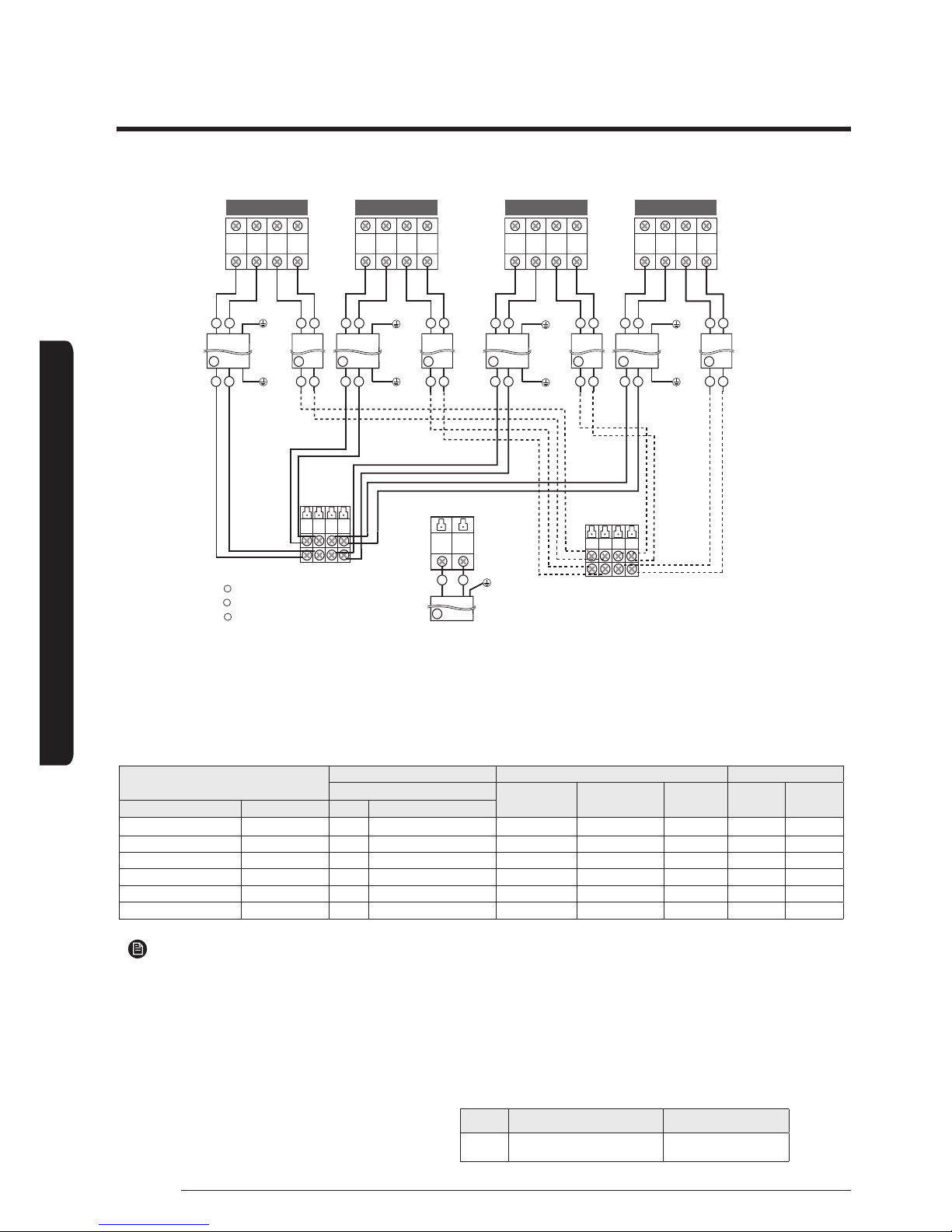
Conncting the cables to the outdoor unit
AJ040/050MCJ2EH
A
B
C
1(L) 2(N) F1 F2 1(L) 2(N) F1 F2
L N
F1 F2
F1 F2
1
2
21
1
2
F1 F2
F1 F2
1 2
1
2
B CB C
A
L N
F1 F2
Indoor unit
Assembly cable
Earth
terminal
Outdoor unit
Main Power
Supply cable
Power cable to indoor units
Communication cable
to indoor units
Cable Type : A
Cable Type : B
Cable Type : C
Earth
terminal
Earth
terminal
Earth
terminal
Earth
terminal
A-unit B-unit
AJ052/068MCJ3EH
L N
1(L) 2(N) F1 F21(L) 2(N) F1 F2
1(L) 2(N) F1 F2
1
2
F1 F2
F1 F2
F1 F2
F1 F2
1
2
21
1
2
F1 F2
F1 F2
1 2
1
2
B
C
B CB C
A
1 2
1(L) 2(N) 1(L) 2(N)
F1 F2 F1 F2
A-unit
B-unit C-unit
Indoor unit
Assembly cable
Earth
terminal
Outdoor unit
Main Power
Supply cable
Power cable to indoor units
Communication cable
to indoor units
A
B
C
Cable Type : A
Cable Type : B
Cable Type : C
Earth
terminal
Earth
terminal
Earth
terminal
Earth
terminal
Earth
terminal
Earth
terminal
10
Installation Procedure
English
Installation Procedure
Specification for circuit breaker and power supply cord
• Power supply cord is not supplied with air conditioner.
• Select the power supply cord in accordance with relevant local and national regulations.
• Wire size must comply with the applicable local and national code.
• Specifications for local wiring power supply cord and branch wiring are in compliance with local cord.
NOTE
1. Power Supply cords of parts of appliances for outdoor use shall not be lighter than polychloroprene sheathed
flexible cord. (Code designation IEC:60245 IEC 57 / CENELEC: H05RN-F , IEC:60245 IEC 66 / CENELEC: H07RN-F )
2. Select power supply cord based on MCA.
3. MFA is used to select the circuit breaker and the ground fault circuit interrupter (earth leakage circuit breaker).
4. MCA represents maximum input current.
5. MFA represents capacity which may accept MCA.
Abbreviations
- MCA : Min. Circuit Amps. (A)
- MFA : Max. Fuse Amps. (A
)
Screw Tighten Torque(kgf.cm) Position
M4 12.0~18.0 1(L),2(L),L,N,F1,F2
Model
Outdoor Units Maximun Input Current[A] Power Supply
Rated
Outdoor Indoor(Max.) Total MCA MFA
Outdoor Unit Indoor Unit Hz Volts
AJ040MCJ2EH 2 Room 50 1phase,220-240 9 0.8 9.8 9.8 11.25
AJ050MCJ2EH 2 Room 50 1phase,220-240 11 0.8 11.8 11.8 13.75
AJ052MCJ3EH 3 Room 50 1phase,220-240 11 1.2 12.2 12.2 13.75
AJ068MCJ3EH 3 Room 50 1phase,220-240 14 1.5 15.5 15.5 17. 5
AJ070MCJ4EH 4 Room 50 1phase,220-240 16.6 2.1 18.7 18.7 20.75
AJ080MCJ4EH 4 Room 50 1phase,220-240 16.6 2.1 18.7 18.7 20.75
AJ070/080MCJ4EH
F1 F2 F1 F2
L N
1(L) 2(N) F1 F2 1(L) 2(N) F1 1(L) 2(N) F1 1(L) 2(N) F1F2
1
2
1 2
F1 F2 F1 F2
1
2
21
F2
1
2
F1 F2
F1 F2
F2
F1 F2
F1 F2
1
2
21
1 2
1
2
B
C B CB C B C
A
1(L) 2(N) 1(L) 2(N)
F1 F2 F1 F2
A-unit B-unit C-unit
D-unit
Indoor unit
Assembly cable
Earth
terminal
Earth
terminal
Outdoor unit
Main Power
Supply cable
Power cable to indoor units
Communication cable
to indoor units
A
B
C
Cable Type : A
Cable Type : B
Cable Type : C
Earth
terminal
Earth
terminal
Earth
terminal
Earth
terminal
Earth
terminal
Earth
terminal
Earth
terminal
11
English
Installation Procedure
• Connect the cables to the terminal board using the compressed ring terminal.
• Use rated cables only.
• Connect the cables with driver and wrench that can apply the rated torque to the screws.
• Make sure that appropriate tightening torque is applied for cable connection. If the terminal is loose, arc heat may
occur and cause fire and if the terminal is connected too firmly, terminal may get damaged.
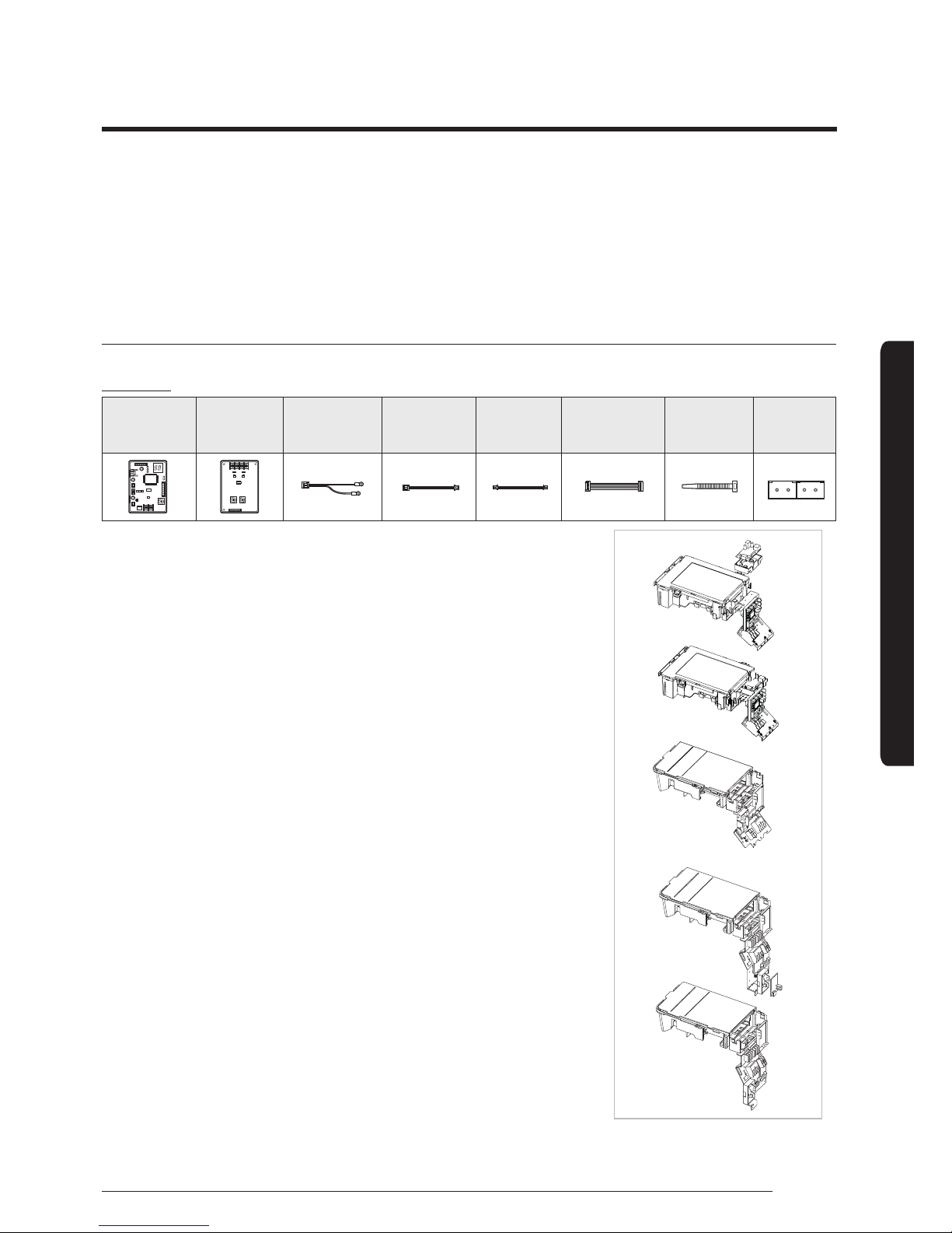
Transmitter installation(option)
• AJ040MJC2EH/AJ050MCJ2EH/AJ052MCJ3EH/AJ068MCJ3EH/AJ070MCJ4EH/AJ080MCJ4EH
Accessories (Transmitter: MIM-B13A)
1.
Turn the power off and take off the cover of the outdoor units.
2. Fix the case with bolts to the side of the control box referring to the figure
on the right side.
In case of FJM outdoor unit, there is not enough space to fix all parts of
transmitter. So you may use transmitter main PCB.
3. Attach the transmitter main PCB to the case, then connect F1/F2 lines,
R1/R2 lines which are upper controller communication cables and DC 12V
power cables to the interface module referring to the figure on page 12.
(Upper controller power should be off.)
4. You must check the position of dip switch on the transmitter's main PCB
and the main PCB of MH∗∗/NJ∗∗ indoor units. For AQV∗∗/AJN∗∗/
AR∗∗ indoor units
5. Assemble a cover of the outdoor unit and turn the power on.
6. Check the communication status.
7. If you install a transmitter to the outdoor unit, every indoor unit which is
connected to the outdoor unit can be controlled simultaneously.
8. Each outdoor unit connected to the same centralized controller has its
own transmitter.
Transmitter
MAIN
Transmitter
SUB
485
Communication
Cable
DC Power
Cable
(12V)
DC Power
Cable
(5V)
Communication
Cable
Cable Tie Case
R1 R2
R2R1 R2 R1
R2R1 R2 R1
Fix the case with hinges
(Control Box in the outdoor unit)
Transmitter
Transmitter
Transmitter
Tightening power terminal
 Loading...