

Samsung AIM-D01AN Service Manual

1. Precautions
2. Product Specifications
3. Disassembly and Reassembly
4. Program Update
5. Troubleshooting
6. PCB Diagram
7. Wiring Diagram
Refer to the service manual in the GSPN(see the rear cover) for the more information.
DMS2.5
CONTENTSDMS2.5
Basic : AIM-D00AN
Model : AIM-D01AN
Model Code : AIM-D01AN
MIM-D01AN
MIM-D01ACN
MIM-D01AUN

Section 0
Samsung Electronics 1
Contents
11. Precautions
....................................................................................................................................................................
1-1
1-1. Precautions for the Service
................................................................................................................................................................
1-1
1-2. Precautions for the Static Electricity and PL
.........................................................................................................................
1-1
1-3. Precautions for the Safety
..................................................................................................................................................................
1-1
12. Product Specifications
........................................................................................................................................
2-1
2-1. The Feature of Product
..........................................................................................................................................................................
2-1
2-2. Product Specifications
.............................................................................................................................................................................
2-2
2-3. System Organization
.................................................................................................................................................................................
2-3
2-4. Main Function
...............................................................................................................................................................................................
2-4
13. Disassembly and Reassembly
......................................................................................................................
3-1
3-1. Disassembly and Reassembly
...........................................................................................................................................................
3-2
3-2. Sub board Disassembly and Reassembly
................................................................................................................................
3-5
3-3. Main board Disassembly and Reassembly
.............................................................................................................................
3-6
3-4. Display board Disassembly and Reassembly
.......................................................................................................................
3-7
14. Program Update
.......................................................................................................................................................
4-1
4-1. Application Update using SD Card
................................................................................................................................................
4-2
15. Troubleshooting
......................................................................................................................................................
5-1
5-1. Items to be checked first
.....................................................................................................................................................................
5-1
5-2. Fault diagnosis by symptom
...........................................................................................................................................................
5-2
5-2-1. When DMS2.5 is not working ......................................................................................................................................... 5-2
5-2-2. When the LCD Display is Not Working or the Backlight is Turing OFF .......................................... 5-4
5-2-3. When the Static LED is Not Turning ON/OFF ..................................................................................................... 5-5
5-2-4. When the RS485 is Not Connecting .......................................................................................................................... 5-6
5-2-5. When the Ethernet is Not Connecting .................................................................................................................... 5-7
5-2-6. When the SD Card is Not Doing Backup Data ................................................................................................... 5-8
5-2-7. When the Button is Not Working ................................................................................................................................ 5-9
5-2-8. Action when the Tracking Error .................................................................................................................................... 5-10
5-2-9. Initialization Way when Admin Password is forgotten .............................................................................. 5-11
5-2-10. If the connection to DMS2 from the outside using internet is not working .......................... 5-12
16. PCB Diagram
...............................................................................................................................................................
6-1
6-1. Main Board
.......................................................................................................................................................................................................
6-1
17. Wiring Diagram
........................................................................................................................................................
7-1

Precautions
Samsung Electronics 1-1
1. Precautions
1-1. Precautions for the Service
●
Use the standard parts when replacing the electric parts.
– Confirm the model name, rated voltage, rated current of the electric parts.
●
Repair the disconnection of HARNESS securely when repairing the break down.
– If there is any connection error, it causes an abnormal noise and incorrect operation.
●
In case that you assemble or disassemble the products with laying it on the side, do work on the work cloth.
– If not, the exterior of products can be scratched.
●
Remove dust and foreign materials from harness, connection part, and inspection part thoroughly when repairing
the break down.
– It protects the danger of fire such as tracking and short.
●
Check the assembly status of parts after repairing the break down.
– It should be same as the status before repairing.
1-2. Precautions for the Static Electricity and PL
●
As the PCB power terminal has a weakness for the static electricity, pay attention to it during the repair and measurement.
– Work with insulation gloves during the repair and measurement of PCB.
●
Check the distance between the product and the other electronic appliances such as TV, video, and audio.
It should be over 2m.
– If not, it causes a bad picture quality or a noise.
●
Repairing the products by consumer should be strictly prohibited.
– There is a danger of electric shock or fire due to incorrect disassembly.
1-3. Precautions for the Safety
●
Do not pull any electric wires and do not touch an auxiliary power switch with a wet hand.
– There is a danger of electric shock or fire.
●
In case any wire or power plug has been damaged, replace it to eliminate any possible danger.
●
Do not bend the power cord by force and do not put any heavy object on the power cord.
– There is a danger of electric shock or fire.
●
Do not use multi socket.
– There is a danger of electric shock or fire.
●
Ground the product if necessary.
– Be sure to ground the product if there is any danger of electric leakage due to water or moisture.
●
Be sure to turn off the auxiliary power switch or pull out the power plug during replacement or repair of electric parts.
– There is a danger of electric shock.

Product specifications & features
Samsung Electronics 2-1
2. Product specifications & features
2-1. The Feature of Product
1) DMS 2.5(AIM-D01AN)
● Control solution product of SAMSUNG electronics for the efficient intergrated management & operation of the system air conditioner.
● Remote connection using internet caused by embedded web server, Possibility of connection to the Remote Management
System(RMS).
● A autonomous performance of functions such as Control information(schedule, peak control) and Use information(electric energy) by
DMS 2.5.
● Possibility of simultaneous using an air conditioner control and a internet in the place that consists of network by Dynamic IP.
2) Main function of DMS 2.5
3) Additional function of DMS 2.5
● DVM Chiller
● Introduction of FCU Kit
ƒEmbedded of web server function.
ƒRemote control/Monitoring.
ƒLogic control of indoor unit operation.
ƒOutdoor air cooling function.
ƒEfficient electric power consumption management.
ƒLong-term effects of electric charge saving.
ƒComposition of 2 modes.
(Priority control, Circulation control)
ƒWeek/Daily, 1 Day repetition.
ƒPossibility up to 256 reservation.
ƒCheck of schedule control history.
ƒIntergrating electric power/gas distribution.
ƒStorage of the data of 256 room, 365 days.
ƒCheck daily electric energy of indoor unit.
ƒ256 indoor unit, ERV operation ON/OFF.
ƒ Operation mode, Air volume, Wind direction,
Temperature setting.
ƒManagement of failure history.
ƒCheck a cycle information of indoor/outdoor unit.
ƒFunction of Security level by user.
DMS2.5
Peak power control
configuration control
Logic
Reading a use of air
conditioner
Schedule
control
Check by remote
control
Control/Monitoring
Product specifications & features
2-2 Samsung Electronics
2-2. Product Specifications
Item Remark
Power
- Adaptor : DC Adapter
- Input Voltage : 100 ~ 240V, 50/60Hz, 1.0A
- Output Voltage : 12V, 3A
Size 240(W)x255(H)x64.8(D) (Unit : mm)
Weight 1.4 8kg
Install Method Panel sticking
Display
LCD(Text)
LED
Power, CPU-Alive, Ethernet Linked, Ethernet Active, COM1, COM2, COM3,
COM4, COM5 TX, RX, Check
KEY
4keys (Menu, ▲ , ▼, Set)
DI / DO
DO(Dry Contact) Digital signal output(8CH)
DI(Dry Contact) Digital signal input(10CH)
Communication
Port
RS485 Connection port of other device besides outdoor unit.
Ethernet RJ45 connector (10/100Mbps) for Ethernet
Etc. Data Backup SD CARD slot (SD card is needed additional purchase)

Product specifications & features
Samsung Electronics 2-3
2-3. System Organization
Internet
S-NET 3
OnO
Controller
Outdoor
Unit
Power Meter
DMS2.5
SIM/PIM

Product specifications & features
2-4 Samsung Electronics
2-4. Main Function
As an Internet based device for centralized management of system airconditioner, supports LAN and WAN.
It can operate for 24 hrs without extra computer.
● 24 Hrs operation
- Convenience with 24hrs, 365 day operation.
● Independent operation and Electricity saving
- Executes Schedule control, Peak electricity control, and Integration power distribution and independently without extra computer.
- Achieves Energy saving with no PC operation at all times.
● Data storage
- Stores and check the list of malfunction, installation information of indoor unit and the data of integration power distribution itself with built-
in database.
● Management of Large quantities units
- The maximum 256 indoor units are connected to one DMS 2.5 realizing efficiency.
● Automatic e-mail
- Sends a e-mail automatically with the list of malfunction to pre-registered address when certain problem occurred.
● Web-server
- You can use various function remotely without extra program.
(Unit condition monitoring, Function control, list of malfunction, schedule setting etc.)
● Linkage with upper-controller
- You can use one central management system with upper-controller (S-net series) combining many DMS 2.5s.

Disassembly and Reassembly
Samsung Electronics 3-1
Item Remark
+Screw Driver
-Screw Driver
3. Disassembly and Reassembly
⸾ Necessary Tools
Disassembly and Reassembly
3-2 Samsung Electronics
3-1. Disassembly and Reassembly
No Parts Procedure Remark
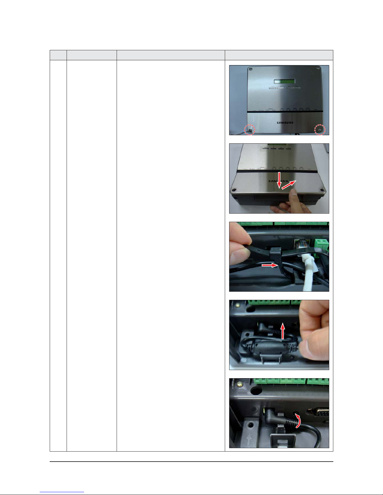
1 Common 1) Unscrew 2 fixing screws.
(Use +Screw Driver)
2) Detach the lower cover.
3) Press lower part of cable tie and detach the
cable tie.
4) Pull the bead-core part of adapter.
5) Turn connector of adapter Counterclockwise.
Disassembly and Reassembly
Samsung Electronics 3-3
No Parts Procedure Remark
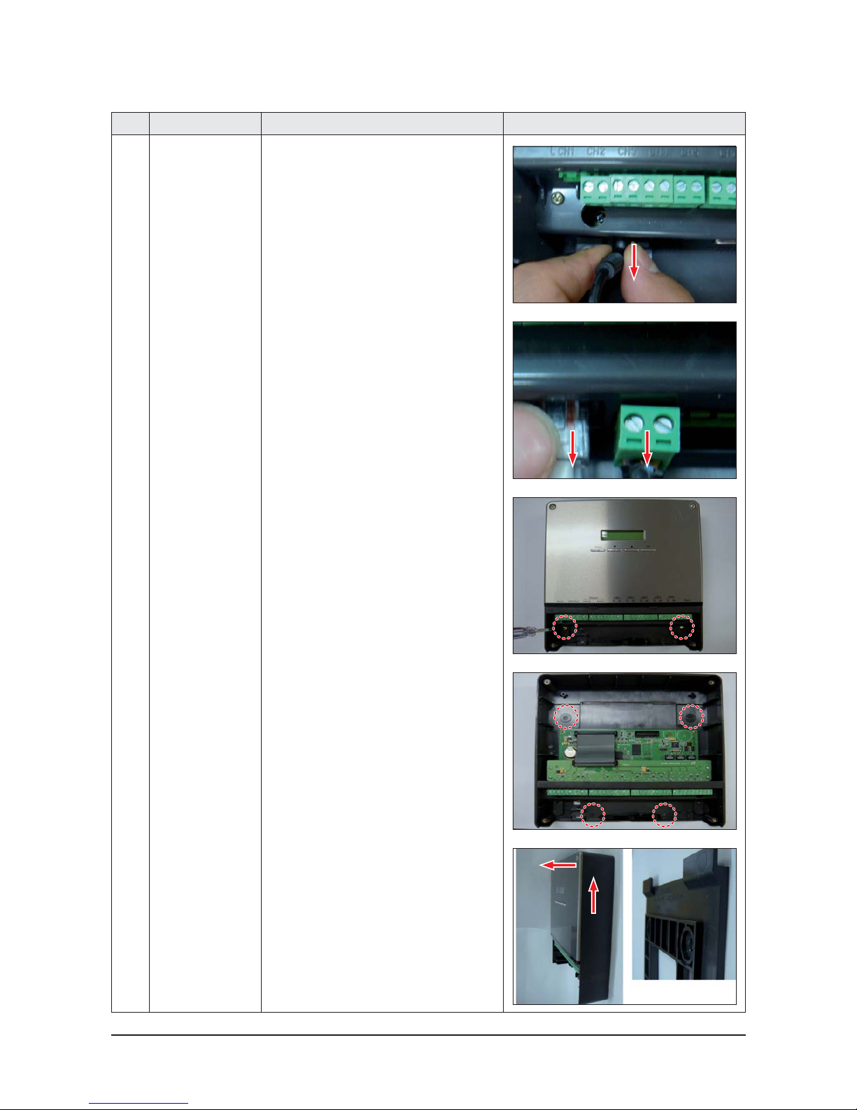
6) Detach the connector of adapter from DMS 2.5.
7) Detach connectors for 485communication,
network and DI/DO.
8) Unscrew at red circle part.
(Use +Screw Driver)
Ref.) The case of using additional Hole for install,
detach from wall after detaching upper cover.
9) Push up DMS 2.5 and pull the DMS 2.5 front
direction.
 Loading...