

ROOM AIR CONDITIONER
INDOOR UNIT
AD26B1C13
AD18B1C09
SERVICE
OUTDOOR UNIT
UD26B1C2
UD18B1C2
Manual
CONTENTSAIR CONDITIONER
1. Installation
2. Disassembly and Reassembly
3. Troubleshooting
4. Exploded Views and Parts List
5. Refrigerating Cycle Block Diagrams
6. Wiring Diagrams
E DB98-05645A(1)
7. Schematic Diagrams
1. Installation
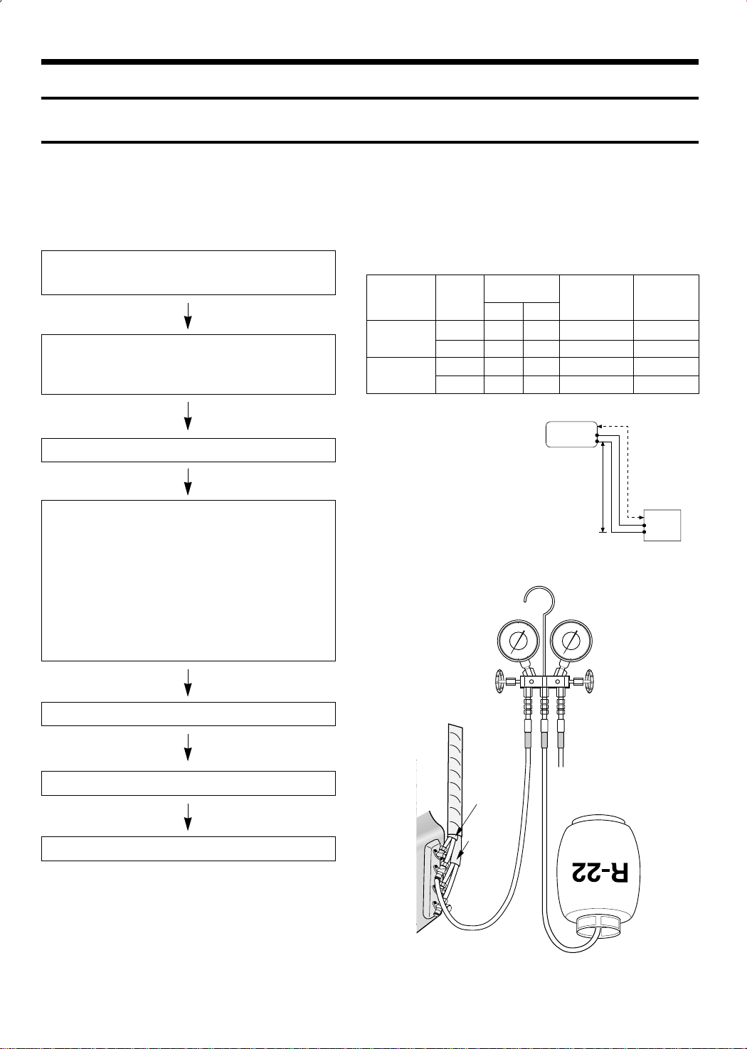
1-1 Refrigerant Refill Procedure
If connecting pipe of more than 5 metres is installed, additional refrigerant should be charged by extra
metre. You don’t have to charge additional refrigerant up to 5 metres of connecting pipe.
1. Remove the valve stem cap and service port of 3-way
valve.
2. Connect the charging hose of low pressure side of
Manifold gauge to the packed valve having a charging
port(1/2” Packed valve) as shown at the right figure.
3. Operate the unit at the cooling mode.
4. Slowly open the valve of the low pressure side of
Manifold gauge counterclockwise until the low pressure
of manifold gauge indicates 4.8 to 5.5 kg/cm
2
(68 a
78psi) at the high cool operation (1-unit operation) and
the standard temperature.
It is recommend that refrigerant should be slowly put in.
If the refrigerant is put in too quickly, compressor will be
damaged.
• Piping length and the height
Pipe Size
LIQUID GAS
AD26B1C13
AD18B1C09
Additional refrigerant charge
(R22,g)
• When length of the pipe is
over 5u by the unit, you
should charge
the refrigerant Formulas
A-UNIT : 20gx(La-5)/m
B-UNIT : 20gx(Lb-5)/m
(La:the length of A-unit’s
pipe Lb:the length of
B-unit’s pipe)
A-UNIT 1/4” 1/2” 15m(49ft 3in) 7m(23ft)
B-UNIT 1/4” 1/2” 15m(49ft 3in) 7m(23ft)
A-UNIT 1/4” 3/8” 15m(49ft 3in) 7m(23ft)
B-UNIT 1/4” 3/8” 15m(49ft 3in) 7m(23ft)
INDOOR UNIT
Max.piping
length
A
B
Max
height
B
A
OUTDOOR UNIT
5. Stop operation of the air conditioner.
6. Disconnect the charge hose of manifold gauge.
7. Close the cap of each valve.
INDOOR
A-UNIT
INDOOR
B-UNIT
1
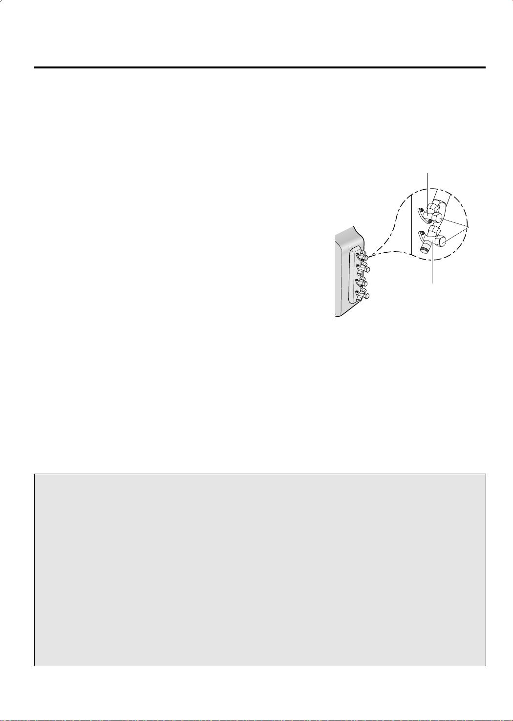
1-2 “Pump down” Procedure
1. Confirm that both the 2-way and 3-way valves are set to
the open position.
(1) Remove the valve stem caps.
(2) Be sure to use a hexagonal wrench to operate the Gas
side valve stems.
2. Operate the unit for 10 to 15 minutes.
3. Stop operation and wait for 3 minutes, then connect the
charge set to the service port of the 3-way valve.
(1) Connect the charge hose with the push pin to the ser-
vice port.
4. Air purging of the charge hose.
(1) Open the low-pressure valve on the charge set slightly
to air purge from the charge hose.
5. Set the liquid side 2-way valve to the closed position.
6. Operate the air conditioner at the cooling cycle and stop
operation immediately after setting the 3-way valve to the
closed position when the gauge indicates 0 kg/cm2G.
If the unit can not be operated at the Cooling Mode(weater
is rather cool), operate the unit at the Trubo Mode.
So that the unit can be operated.
7. Disconnect the charge set, and mount the both 3-way
valve’s stem nuts and the service port cap.
2-Way Valve
Cap
3-Way Valve
Relocation of the air conditioner
• Refer to this procedure when the unit is relocated.
1. Carry out the pump down procedure
(refer to the details of ‘pump down’).
2. Remove the power cord.
3. Disconnect the assembly cable from the
indoor and outdoor units.
4. Remove the flare nut connecting the indoor
unit and the pipe.
At this time, cover the pipe of the indoor
unit and the other pipe using a cap or vinyl
plug to avoid foreign material entering.
2
5. Disconnect the pipe connected to the outdoor unit.
At this time, cover the valve of the outdoor
unit and the other pipe using a cap or vinyl
plug to avoid foreign material entering.
6. Make sure you do not bend the connection
pipes in the middle and store together with
the cables.
7. Move the indoor and outdoor units to a new
location.
8. Remove the mounting plate for the indoor
unit and move it to a new location.
2. Disassembly and Reassembly
Stop operation of the air conditioner and remove the power cable before repairing the unit.
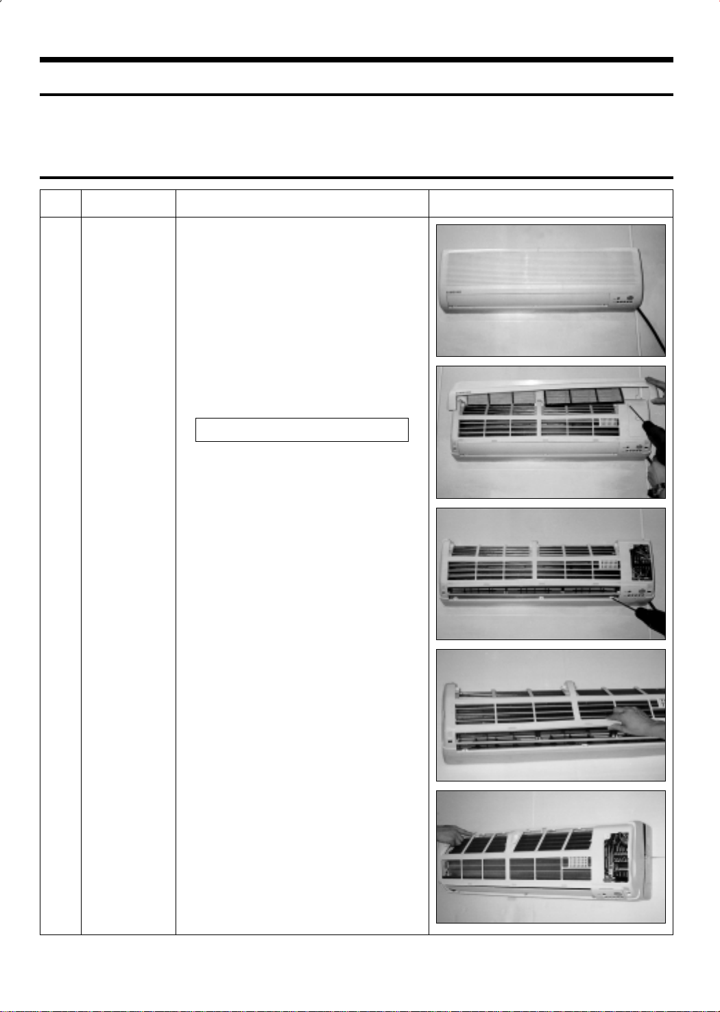
2-1 Indoor Unit
No Parts Procedure Remark
Front Grille1 1) Stop the air conditioner operation and block the
main power.
2) Separate tape of front panel upper.
3) Contract the second finger to the left, and right
handle and pull to open the inlet grille.
4) Take the left and right filter out.
*Taking off the deodorizing filter.
5) Loosen one of the right fixing screw and separate the terminal cover.
6) Loosen three fixing screws of front grille.
7) Pull the upper left and right of discharge softly
for the outside cover to be pulled out.
8) Pull softly the lower part of discharge and push
it up.
Caution;
Assemble the front panel and fix the
hooks of left and right.
3
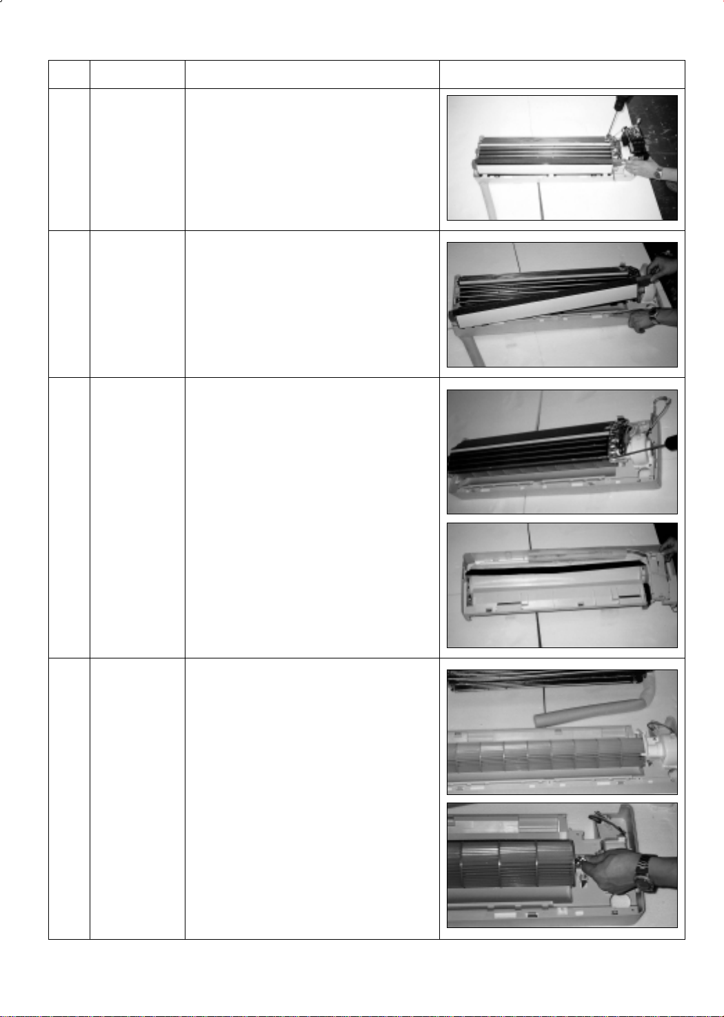
No Parts Procedure Remark
2
3
4
Electrical Parts
(Main PCB)
Ass’y Tray Drain.
Heat Exchanger
1) Do “1”above.
2) Take all the connector of PCB upper side out.
(Inclusion Power cord)
3) Separate the outdoor unit connection wire from
the terminal block.
4) If pulling the Main PCB up. it will be taken out.
1) Do “1”, “2”, above.
Separate the drain hose from the extension
drain hose.
2) Pull tray drain out from the back body.
1) Do “1” and “2”, “3”, above.
2) Loosen two fixing earth screws of right side.
3) Separate the connection pipe.
4) Separate the holder pipe at the rearside.
5
Fan Motor and
Cross Fan
5) Loosen the three fixing screws of right and left
side.
6) Lifting the heat exchanger up a little to push the
up side for separation from the indoor unit.
1) Do “1”, “2”, ”3”, “4”, above.
2) Loosen the fixing two screws and separate the
motor holder.
3) Loosen the fixing screw of fan motor.
(By use of M3 wrench)
4) Separate the fan motor from the fan.
5) Separate the fan from the left holder bearing.
4
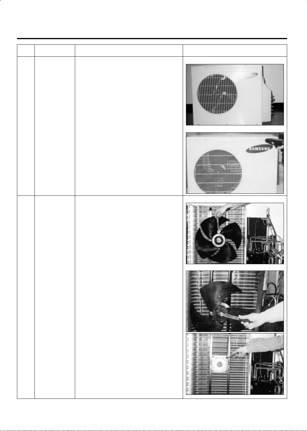
2-2 Outdoor Unit
No Parts Procedure Remark
1
2
Cabinet
Fan Motor
&
Propeller Fan
1) Turn off the unit and remove the power cable.
2) Remove the top cover.
3) Remove the control box cover.
4) Unplug the ass'y cable.
5) Remove the cabi-side.
6) Remove the cabi-front.
* When you assemble the parts, check if the
each parts and electric connectors are fixed
firmly.
1) Do Procedure “1” above.
2) Remove the nut flange.
(Turn to the right to remove as it is a left turned
screw)
3) Disassemble the propeller fan.
<UD26B1C2>
<UD18B1C2>
<UD26B1C2>
<UD18B1C2>
5
3. Troubleshooting
3-1 Items to be checked first
1) The input voltage should be rating voltage ±10% range.
The airconditioner may not operate properly if the voltage is out of this range.
2) Is the link cable linking the indoor unit and the outdoor unit linked properly?
The indoor unit and the outdoor unit shall be linked by 5 cables.
Check the terminals if the indoor unit and outdoor unit are properly linked by the same number
of cables. Otherwise the airconditioner may not operate properly.
3) When a problem occurs due to the contents illustrated in the table below it is a symptom not
related to the malfunction of the airconditioner.
NO Operation of air conditioner
1 The STD operation indication LED blinks when a
power plug of the indoor unit is plugged in for the first time.
2 In a COOL operation mode, the compressor does not
operate at a room temperature higher than the setting
temperature that the IN DOOR FAN should operate.
In a HEAT operation mode, the compressor does not
operate at a room temperature lower than the setting
temperature that indoor fan should operate.
3 Fan speed setting is not allowed in AUTO or DRY mode.
4 Compressor stops operation intermittently in DRY mode.
5 Compressor of the outdoor unit is operating although it is
turned off in a HEAT mode.
6 Timer LED only of the indoor unit lights up and the
air conditioner does not operate.
7 The compressor and indoor fan stop intermittently in HEAT
mode.
8 Indoor fan and outdoor fan stop operation intermittently in
a HEAT mode.
Explanation
It indicates power is on. The LED stops blinking if the operation
ON/OFF button on the remote control unit is pushed.
In happens after a delay of 3 minutes when the compressor is
reoperated. The same phenomenon occurs when a power is on.
As a phenomenon that the compressor is reoperated after a delay
of 3 minutes, the indoor fan is adjusted automatically with reference to a temperature of the air blew
The speed of the indoor fan is set to LL in DRY mode.
Fan speed is 5 steps is selected automatically in AUTO mode.
Compressor operation is controlled automatically in DRY mode
depending on the room temperature and humidity.
When the unit is turned off while de-ice is activated, the compressor continues operation for up to 9 minutes (maximum) until
the deice is completed.
Timer is being activated and the unit is in ready mode.
The unit operates normally if the timer operation is cancelled.
The compressor and indoor fan stop intermittently if room temperature exceeds a setting temperature in order to protect the compressor from overheated air in a HEAT mode.
The compressor operates in a reverse cycle to remove exterior ice
in a HEAT mode, and indoor fan and outdoor fan do not operate
intermittently for within 20% of the total heater operation
9 The compressor stops intermittently in a COOL mode or DRY
mode, and fan speed of the indoor unit decreases.
6
The compressor stops intermittently or the fan speed of the indoor
unit decreases to prevent inside/outside air frozen depending on
the inside/outside air temperature.
4) Indoor unit observes operation condition of the air conditioner, and displays self diagnosis details
on the display panel.
NO
Display
Standard Timer Nature Power
(GREEN)
1
2
3
4
5
6
7
X
(GREEN)
X
X
(GREEN)
(GREEN)
X
X
X
X
X
X
X
Self Diagnosis
Restore from power failure (input initial power)
X
Indoor unit Room sensor Error (open or short)
X
Indoor unit heat exchanger temperature sensor Error (open or short)
X
Indoor fan malfunctioning (for speed is below 450rpm)
X
In case that the communication between the indoor unit and outdoor unit is not made
X
for 60 seconds
Outdoor sensor Error (open or short)
- Outdoor sensor
X
- Pipe sensor A, B
The malfunction ot 4way valve in heat mode operation.
7
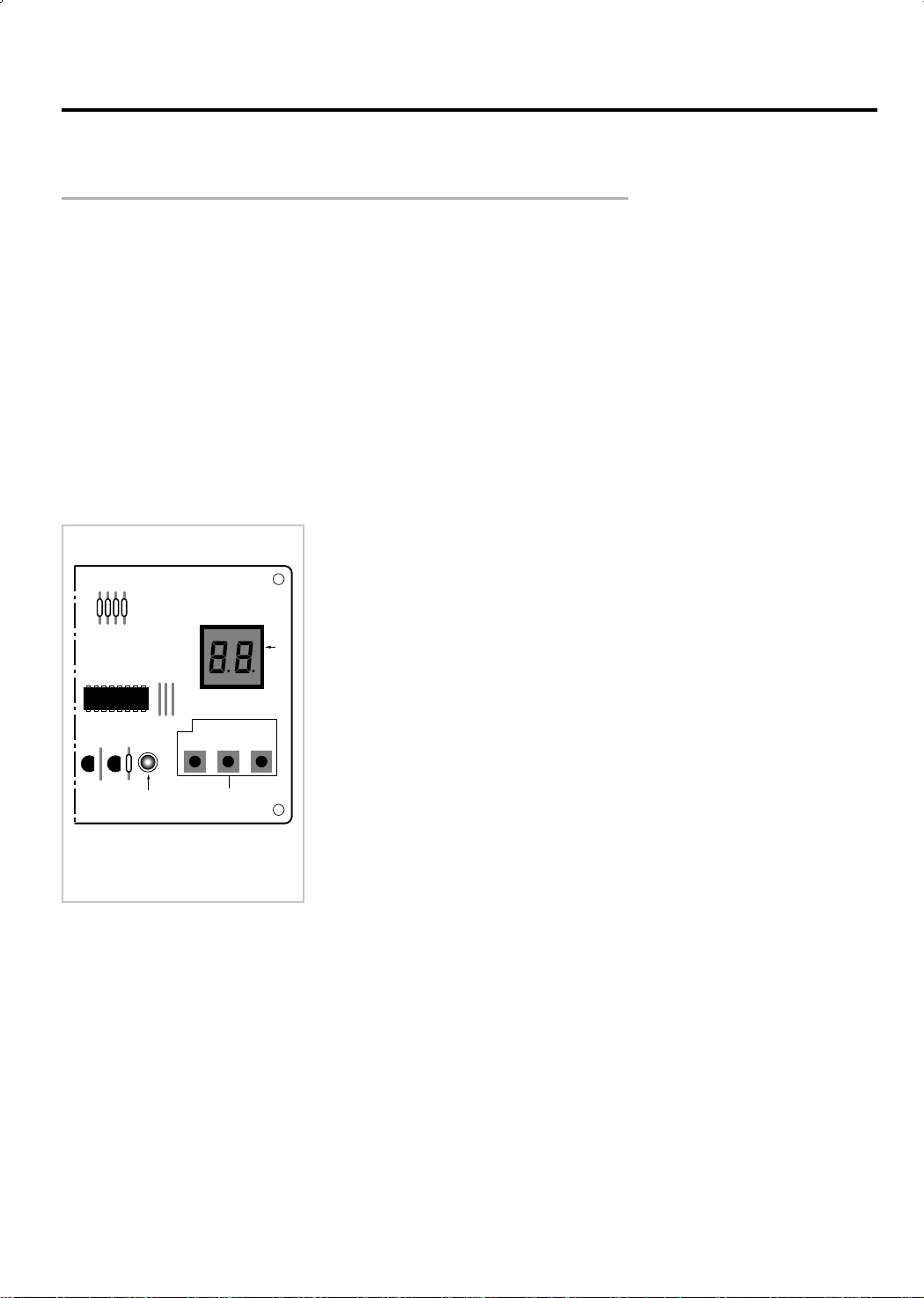
3-2 Checking and Testing Operations (Outdoor Unit)
C
a
b
TEST OPERATING
CB
A
To complete the installation, perform the following checks and tests to ensure that
the air conditioner is operating correctly.
1. Review all the following elements in the installation:
• Installation site strength
• Piping connection tightness to detect any gas leakages
• Connection wiring
• Heat-resistant insulation of the piping
• Drainage
• Earthing wire connection
• Correct operations (follow the steps below)
• Room select switch in the indoor unit
2. Apply the power to the outdoor unit.
- Check the fuse (250V~, 5A) : The fuse is open when the power line (L1, N2) is short.
OUTDOOR UNIT
A : PCB display
B : Red LED
C : PCB switch
3. Check the connection of PCB communication of outdoor unit.
(Check whether the red LED of outdoor unit PCB is flickering.)
• The communication lamp is flickering after the display of each
unit on the outdoor PCB display part. (every one second).
LED is not flikering, if the connection is bad or the room select
switch is located in the wrong position.
- LED lamp (red) flickering after display of A (0.5 sec)
- LED lamp (red) flickering after display of b (0.5 sec)
- LED lamp (red) flickering after display of C (0.5 sec)
Note : PCB switch “C” is used for triple split multi air conditioner.
Result : If all of three units display lamps are flickering, the connection
wires and the room option connections are good.
8
If the lamp is not flickering, check as follows:
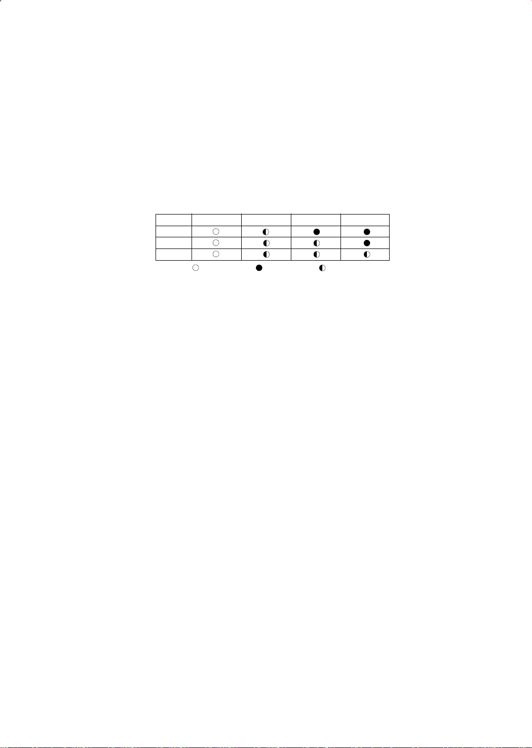
A. Check the display part of indoor unit of each unit (A,B) after outdoor unit PCB switch S/W-Ais on.
A. Check the status of each unit indoor room select switch.
A. (Adjust the select switch suitable to the unit A, B.)
A. - A unit : STANDARD LED on, TIMER LED flickering
A. - B unit : STANDARD LED on, TIMER and NATURE LED flickering
A. - C unit : STANDARD LED on, TIMER and NATURE, POWER LED flickering (In case of triple
split multi air conditioner)
UNIT
STANDARD TIMER NATURE POWER
A
B
C
Lamp ON
Lamp OFF Lamp Flasher
4. Check the test operation status by pressing the PCB switch
4. S/W-A and S/W-B of outdoor unit.
4. • Check the operation status by pushing the switch one at time.
4. • Perform the test operation only for the unit selected last.
4. • Check the pipe pressure and the other operation status during the test operation.
4. • Check items when the error occurs during the test operation (each unit)
- Check there is enough refrigerant.
- Check pipe connections.
9
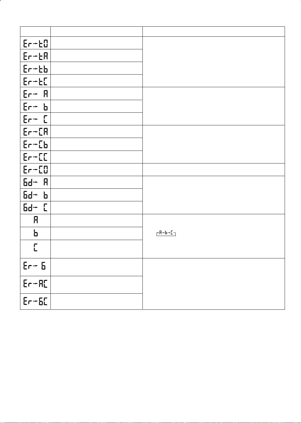
DISPLAY EXPLANATION
REMARK
Outdoor sensor error (Short/Open)
Outdoor A cond pipe sensor error (Short/Open)
Outdoor B cond pipe sensor error (Short/Open)
Outdoor C cond pipe sensor error (Short/Open)
A unit test operation error
B unit test operation error
C unit test operation error
A unit test communication error
B unit test communication error
C unit test communication error
A,B,C unit all communication error
A room test operation OK
B room test operation OK
Be sure to check after applying the power to the outdoor unit.
Display when the test operation finishes.
• When the pipe temperature difference of indoor unit
• (pipe temperature 4 minutes before - Actual pipe temperature)
• is less than 5˚C.
Be sure to check during the test operation.
Display of power application.
Display 4 minutes after the COMP is on.
C room test operation OK
Communication unit number display : A unit
Communication unit number display : B unit
Communication unit number display : C unit
(In case of triple split multi air conditioner)
Refrigerant leaks
High temperature of the A cond
High temperature of the B cond
•Normal operation
•Unit A,B and C are changed every one second.
•The communication lamp is flickering after display of each unit.
•(possibility to check the communication status)
•During the test operation the unit under test is on and off every 0.25s.
10
3-3 Fault Diagnosis by Symptom
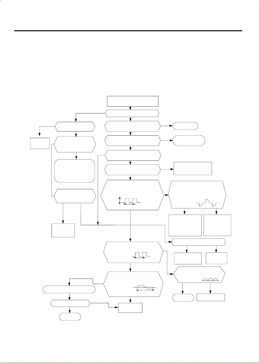
3-3-1 No Power (completely dead)-Initial diagnosis
1) Checklist :
(1) Is input voltage normal?
(2) Is AC power linked correctly?
(3) Is output voltage of DC regulator IC KA7805 (IC02) normal? (4.5VDC-5.5VDC)
2) Troubleshooting procedure
Remove power cord and plug in
again in approx. 5 seconds
YES
Replace
PCB display
Is DC voltage of PCB
display normal?
NO
Is rating voltage ±10%
range applied to the
primary side (~,~)
of the “BD71”
NO
•Check linkage between
power cord and
terminal tap
•Check fuse
Is 14~18VAC appear in
the secondary side (+, -)
of “BD71”
NO
Replace
SMPS PARTS
Replace resonator (X301)
Is operation normal?
YES
YES
OK
NO
Is operation lamp blinking?
Does operation start when
run/stop button on the remote
controller unit pushed?
Is transmission display of the
remote controller unit blinking?
Is "beep"sound heard from the
NO
Is DC voltage of the PCB module
5VDC Is voltage of #60 (indoor fan)
DC5V
Is voltage at #52 terminal of the
Are voltage at #48 and #49 of the
NO
NO
main unit?
normal?
of the micom normal?
10ms
micom normal?
micom normal?
Replace micom
YES
NO
YES
YES
YES
NO
YES
YES
10ms
250ns
YES
NO
NO
YES
NO
Normal
Refer to remote control
unit fault diagnosis
Replace PCB module.
Is voltage at SS71(indoor fan)
Check connections
compressor 4-way
valve, outdoor fan and
indoor fan.
Is output voltage of ICO2 normal?
Check PCB pattern.
Replace main PCB.
Is voltage output terminal of
TLP180(PC02) normal?
YES
OK
DC12V
YES
Replace RY71,
RY73, RY72 and
YES
Replace ICO2
Replace TLP180(pc02)
NO
SS71
NO
NO
11
 Loading...