

Samsung 920NW Service Manual

SERVICE
Manual
LCD Monitor
Fashion Feature
LCD-Monitor
Model 920NW
- 19" LCD Monitor (1440x 900 )
- Response Time (5ms)
- Simple Stand
- Silver / Black ColorVariation

ii
Copyright
©2007 by Samsung Electronics Co., Ltd.
All rights reserved.
This manual may not, in whole or in part, be copied,
photocopied, reproduced, translated, or converted to
any electronic or machine readable form without prior
written permission of Samsung Electronics Co., Ltd.
920NW Service Manual
First edition July 20067.
Printed in Korea.
Trademarks
Samsung is the registered trademark of Samsung
Electronics Co., Ltd.
920NW and MacMaster Cable Adapter are trademarks
of Samsung Electronics Co., Ltd.
Macintosh, Power Macintosh are trademarks of Apple
Computer, Inc.
All other trademarks are the property of their respective
owners.

11. Precautions
………………………………………………………………………………………………………………………………………
11-1
1-1 Safety Precautions ……………………………………………………………………………………………………………………… 1-1
1-2 Servicing Precautions …………………………………………………………………………………………………………………… 1-2
1-3 Electrostatically Sensitive Devices (ESD) Precautions ……………………………………………………………………………… 1-2
1-4 Installation Precautions ………………………………………………………………………………………………………………… 1-3
2
2. Product specifications
…………………………………………………………………………………………………………………………
22-1
2-1 Fashion Feature…………………………………………………………………………………………………………………………… 2-1
2-2 Specifications ……………………………………………………………………………………………………………………………… 2-1
2-3 Option Specification ……………………………………………………………………………………………………………………… 2-2
3
3. Alignments and Adjustments
…………………………………………………………………………………………………………………
33-1
3-1 Required Equipment …………………………………………………………………………………………………………………… 3-1
3-2 Automatic Color Adjustment …………………………………………………………………………………………………………… 3-1
3-3 DDC EDID Data Input …………………………………………………………………………………………………………………… 3-1
3-4 How to execute DDC …………………………………………………………………………………………………………………… 3-2
3-5 How to execute MCU Code ……………………………………………………………………………………………………………… 3-3
4
4. Troubleshooting
………………………………………………………………………………………………………………………………
44-1
4-1 Common Acknowledge ……………………………………………………………………………………………………………………4-1
4-2 No Power & Power LED Off …………………………………………………………………………………………………………… 4-2
4-3 DC output voltage is unstable …………………………………………………………………………………………………………… 4-3
4-4 Output power is unstable ………………………………………………………………………………………………………………… 4-4
4-5 Backlight can't be turned on …………………………………………………………………………………………………………… 4-5
4-6 Black Screen and backlight turn on …………………………………………………………………………………………………… 4-6
4-7 White Screen ……………………………………………………………………………………………………………………………… 4-7
4-8 Bad Screen ………………………………………………………………………………………………………………………………… 4-8
5
5. Exploded View and Parts List
………………………………………………………………………………………………………………
55-1
6. EElectrical Parts List
……………………………………………………………………………………………………………………………
66-1
7. BBlock Diagram
…………………………………………………………………………………………………………………………………
77-1
7-1 Power tree …………………………………………………………………………………………………………………………………7-1
7-2 Mainboard part ……………………………………………………………………………………………………………………………7-2
7-3 IP Board Part(SMPS Part) ………………………………………………………………………………………………………………7-2
7-4 IP BOARD part(Inverter Part) ……………………………………………………………………………………………………………7-3
8
8. Wiring Diagram
…………………………………………………………………………………………………………………………………
88-1
Contents

99. Schematic Diagrams
……………………………………………………………………………………………………………………………
99-1
9-1 INPUT ……………………………………………………………………………………………………………………………………… 9-1
9-2 DCINPUT ……………………………………………………………………………………………………………………………………9-2
9-3 SCALER
……………………………………………………………………………………………………………………………………9-3
9-4 POWER
……………………………………………………………………………………………………………………………………9-4
9-5 POWER ……………………………………………………………………………………………………………………………………9-5
9-6 KEYPAD
……………………………………………………………………………………………………………………………………9-6
110. Operating Instructions and Installation ………………………………………………………………………………………………………10-1
10-1 Front …………………………………………………………………………………………………………………………………… 10-1
10-2 Rear
………………………………………………………………………………………………………………………………………10-2
10-3 Monitor Assembly ………………………………………………………………………………………………………………………10-3
10-4 Attaching a Base
………………………………………………………………………………………………………………………10-4
1
11. Disassembly and Reassembly
………………………………………………………………………………………………………………
111-1
11-1 Disassembly Block …………………………………………………………………………………………………………………… 11-1
11-2 Reassembly …………………………………………………………………………………………………………………………… 11-4
1
12. PCB Diagram
…………………………………………………………………………………………………………………………………
112-1
13. CCircuit Descriptions
……………………………………………………………………………………………………………………………
113-1
13-1 Overall Block Structure ……………………………………………………………………………………………………………… 13-1
13-2 IP BOARD part(Inverter Part) ………………………………………………………………………………………………………… 13-4
1
14. Reference Infomation ………………………………………………………………………………………………………………………… 14-1
14-1 Technical Terms ……………………………………………………………………………………………………………………… 14-1
14-2 Connecting the monitor …………………………………………………………………………………………………………………14-3
14-3 Pin Assignments…………………………………………………………………………………………………………………………14-4
14-4 Timing Chart ……………………………………………………………………………………………………………………………14-5
14-5 Preset Timing Modes ………………………………………………………………………………………………………………… 14-6
14-6 Panel Description ……………………………………………………………………………………………………………………… 14-7
Contents
Samsung Electronics Co.,Ltd.
416, Maetan-3Dong, Yeongtong-Gu, Suwon City,
Gyeonggi-Do, Korea, 443-742
Printed in Korea
P/N : BN82URL : http://itself.sec.samsung.co.kr/
-This Service Manual is a property of Samsung
Electronics Co., Ltd.
Any unauthorized use of Manual can be punished
under applicable International and/or domestic
law.
1 Precautions
1-1
1-1-1 Warnings
1. For continued safety, do not attempt to modify the circuit
board.
2. Disconnect the AC power and DC power jack before
servicing.
1-1-2
Ser vicing the LCD Monitor
1. When servicing the LCD Monitor, Disconnect the AC
line cord from the AC outlet.
2. It is essential that service technicians have an accurate
voltage meter available at all times. Check the
calibration of this meter periodically.
1-1-3 Fire and Shock Hazard
Before returning the monitor to the user, perform the
following safety checks:
1. Inspect each lead dress to make certain that the leads are
not pinched or that hardware is not lodged between the
chassis and other metal parts in the monitor.
2. Inspect all protective devices such as nonmetallic control
knobs, insulating materials, cabinet backs, adjustment
and compartment covers or shields, isolation resistorcapacitor networks, mechanical insulators, etc.
3. Leakage Current Hot Check (Figure 1-1):
WARNING : Do not use an isolation
transformer during this test.
Use a leakage current tester or a metering system that
complies with American National Standards Institute
(ANSI C101.1, Leakage Current for Appliances), and
Underwriters Laboratories (UL Publication UL1410,
59.7).
Figure 1-1. Leakage Current Test Circuit
4. With the unit completely reassembled, plug the AC line
cord directly into a 120V AC outlet. With the unit’s AC
switch first in the ON position and then OFF, measure
the current between a known earth ground (metal water
pipe, conduit, etc.) and all exposed metal parts,
including: metal cabinets, screwheads and control shafts.
The current measured should not exceed 0.5 milliamp.
Reverse the power-plug prongs in the AC outlet and
repeat the test.
1-1-4 Product Safety Notices
Some electrical and mechanical parts have special safetyrelated characteristics which are often not evident from visual
inspection. The protection they give may not be obtained by
replacing them with components rated for higher voltage,
wattage, etc. Parts that have special safety characteristics are
identified by on schematics and parts lists. A substitute
replacement that does not have the same safety characteristics
as the recommended replacement part might create shock, fire
and/or other hazards. Product safety is under review
continuously and new instructions are issued whenever
appropriate.
1 Precautions
Follow these safety, servicing and ESD precautions to prevent damage and to protect against potential hazards such as electrical shock.
1-1 Safety Precautions

1 Precautions
1-2
1-2-1 General Ser vicing
Precautions
1. Always unplug the unit’s AC power cord from the AC
power source and disconnect the DC Power Jack before
attempting to:
(a) remove or reinstall any component or assembly, (b)
disconnect PCB plugs or connectors, (c) connect a test
component in parallel with an electrolytic capacitor.
2. Some components are raised above the printed circuit
board for safety. An insulation tube or tape is sometimes
used. The internal wiring is sometimes clamped to
prevent contact with thermally hot components. Reinstall
all such elements to their original position.
3. After servicing, always check that the screws,
components and wiring have been correctly reinstalled.
Make sure that the area around the serviced part has not
been damaged.
1. Immediately before handling any semiconductor
components or assemblies, drain the electrostatic charge
from your body by touching a known earth ground.
Alternatively, wear a discharging wrist-strap device. To
avoid a shock hazard, be sure to remove the wrist strap
before applying power to the monitor.
2. After removing an ESD-equipped assembly, place it on a
conductive surface such as aluminum foil to prevent
accumulation of an electrostatic charge.
3. Do not use freon-propelled chemicals. These can
generate electrical charges sufficient to damage ESDs.
4. Use only a grounded-tip soldering iron to solder or
desolder ESDs.
5. Use only an anti-static solder removal device. Some
solder removal devices not classified as “anti-static” can
generate electrical charges sufficient to damage ESDs.
4. Check the insulation between the blades of the AC plug
and accessible conductive parts (examples: metal panels,
input terminals and earphone jacks).
5. Insulation Checking Procedure: Disconnect the power
cord from the AC source and turn the power switch ON.
Connect an insulation resistance meter (500 V) to the
blades of the AC plug.
The insulation resistance between each blade of the AC
plug and accessible conductive parts (see above) should
be greater than 1 megohm.
6. Always connect a test instrument’s ground lead to the
instrument chassis ground before connecting the positive
lead; always remove the instrument’s ground lead last.
6. Do not remove a replacement ESD from its protective
package until you are ready to install it. Most
replacement ESDs are packaged with leads that are
electrically shorted together by conductive foam,
aluminum foil or other conductive materials.
7. Immediately before removing the protective material
from the leads of a replacement ESD, touch the
protective material to the chassis or circuit assembly into
which the device will be installed.
Caution:Be sure no power is applied to the
chassis or circuit and observe all
other safety precautions.
8. Minimize body motions when handling unpackaged
replacement ESDs. Motions such as brushing clothes
together, or lifting your foot from a carpeted floor can
generate enough static electricity to damage an ESD.
1-3 Static Electricity Precautions
Some semiconductor (solid state) devices can be easily damaged by static electricity. Such components are commonly called
Electrostatically Sensitive Devices (ESD). Examples of typical ESD are integrated circuits and some field-effect transistors. The
following techniques will reduce the incidence of component damage caused by static electricity.
1-2 Ser vicing Precautions
WARNING: An electrolytic capacitor installed with the wrong polarity might explode.
Caution: Before servicing units covered by this service manual, read and follow the Safety Precautions section
of this manual.
Note: If unforeseen circumstances create conflict between the following servicing precautions and any of the safety
precautions, always follow the safety precautions.

1 Precautions
1-3
1-4 Installation Precautions
1. For safety reasons, more than two people are
required for carrying the product.
2. Keep the power cord away from any heat emitting
devices, as a melted covering may cause fire or
electric shock.
3. Do not place the product in areas with poor
ventilation such as a bookshelf or closet. The
increased internal temperature may cause fire.
4. Bend the external antenna cable when connecting
it to the product. This is a measure to protect it
from being exposed to moisture. Otherwise, it
may cause a fire or electric shock.
5. Make sure to turn the power off and unplug the
power cord from the outlet before repositioning
the product. Also check the antenna cable or the
external connectors if they are fully unplugged.
Damage to the cord may cause fire or electric
shock.
6. Keep the antenna far away from any high-voltage
cables and install it firmly. Contact with the highvoltage
cable or the antenna falling over may
cause fire or electric shock.
7. When installing the product, leave enough space
(10cm) between the product and the wall for
ventilation purposes.
A rise in temperature within the product may
cause fire.

1 Precautions
1-4
Memo
2 Product Specifications
2-1
2 Product Specifications
2-1 Fashion Feature
- 19" LCD Monitor (1440x 900 )
- Response Time (5ms)
- Simple Stand
- Silver / Black ColorVariation
Size 19" Diagonal (41 x 27cm)
Pixel Pinch 0.285(H) x 0.285(V)
Frequency
Horizontal / Vertical 30 ~ 81 kHz/ 56 ~ 75 Hz
Bandwidth (MHz) 140MHz
Resolution 1440 x 900@60Hz
Color Sliver & Black
Signal Input
Sync. Type Separate/Composite/No Sync. On Green
Video Input Analog Signal Level
Power Consumption Max 36 W
Power saving <1W
Stand Yes
Swivel ( left / right ) NO
Power Supply AC 100 ~ 240 VAC(+/-10 %) , 60/50 Hz ± 3 Hz
Dimension (W x D x H) 439.006 x 289.006 x 65.45 mm
3
(Without Stand)
439.006x355.452x81.12 mm
3
(With Simple Stand)
Specifications
Features
2-2 Specifications
2 Product Specifications
2-2
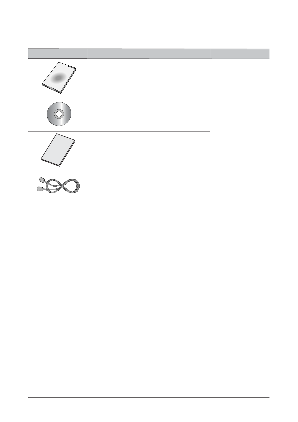
2-3 Option Specification
Item Item Name CODE.NO Remark
GUIDE, QUICK SETUP
BH68-00376L-04
BN59-00537A-00
N/A
MNL User's(CD)
D-Sub Cable
BH68-70438A-10
CARS, WARRANTY
3 Alignments and Adjustments
3-1
3-1 Required Equipment
The following equipment is necessary for adjusting the monitor:
Computer with Windows 95, Windows 98, Windows NT, Windows 2000, or Windows XP.
MTI-2031 DDC MANAGER JIG
3-2 Automatic Color Adjustment
To Analog video, In 16gray or any pattern using black and white and any mode.(16gray and XGA mode recommend)
1. Push the OSD Menu button to open the OSD
2. Selectl language English
3. Push enter button during 5 seconds.
4. See the screen flashing
3-3 DDC EDID Data Input
1. Input DDC EDID data when replacing AD PCB.
2. Receive/Download the proper DDC file for the model from HQ quality control department.
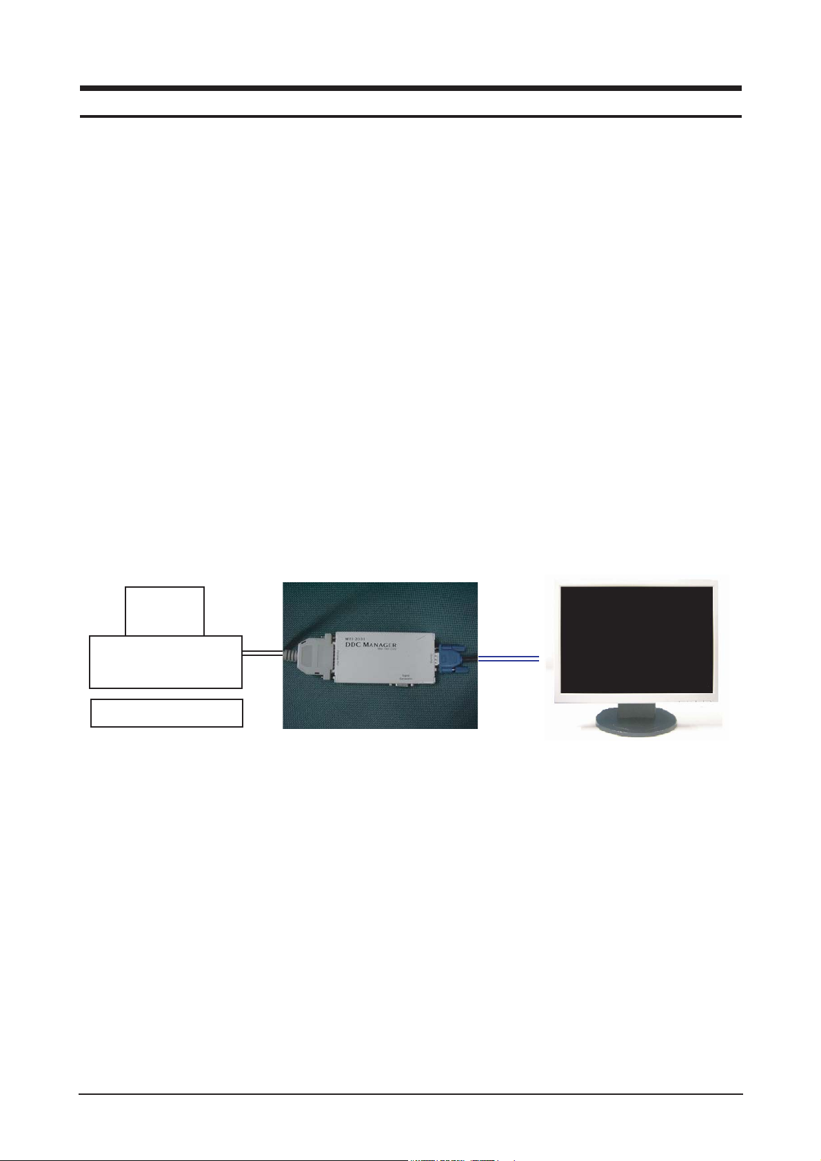
Install the below jig (Figure 1) and enter the data.
3 Alignments and Adjustments
This section of the service manual explains how to use the RS232 JIG.
This function is needed for AD board change.
Figure 1.
Monitor
PC
PC for JIG

3-4 VGA EDID table
Details:
3 Alignments and Adjustments
3-2
0123 456 789ABCDEF
000FFFFFF FFFFFF004C2D2B02XXXXXXXX
1XXXX0103 6C221B782ADC55A359489E24
2115054BFEF808180714F814001010101
3010101010101302A009851002A403070
41300520E1100001E000000FD00384B1E
5510E000A202020202020000000FC0053
6796E634D61737465720A2020000000FF
700XXXXXXXXXXXXXXXXXXXX0A20 20 00CS
Byte(Hex) Field Name and Comments Description EDID
00-07(8 byte) Head Information 00,FF,FF,FF,
FF, FF, FF,00
08--09 ID Manufacturer Name SAM 4C,2D
0A--0B Product ID Code 022B 2B,02
0C--0F Last 5 Digits of Serial Number Used Notes1 XX,XX,XX,XX
10 Week of Manufacture Notes2 XX
11 Year of Manufacture Notes3 XX
12 EDID Version Number 1 01
13 EDID Revision Number 3 03
14 Video Input Definition Analog Signal 6C
0.700,0.000(0.700Vpp)
Separate Sync
Composite Sync
15 Max Horizontal Image Size (cm) 34 22
16 Max Vertical Image Size (cm) 27 1B
17 Display Gamma 2.2 78
18 Power Management and Active Off 2A
Supported Feature(s) Display Type = R/G/B Color
Preferred Timing Mode
19-22 (10 byte) Chroma Info Red X - 0.640, Red Y - 0.349, DC,55,A3,59,
Green X - 0.284, 48,9E, 24,11,
Green Y - 0.617, 50,54
Blue Y - 0.067, Blue X - 0.142,
White X - 0.313,
White Y - 0.329
23 Established Timing I 720x400@70Hz BF
720x400@88Hz(no)
640x480@60Hz
640x480@67Hz
640x480@72Hz
640x480@75Hz
800x600@56Hz
800x600@60Hz
3 Alignments and Adjustments
3-3
Remark:
Notes1: Get SerialNumber(10----14Digit) from BarCode and transfer it to HEX
Notes2: Week(1---53),
Notes3: Year , HEX(Year-1990) ,
Notes4: Get Barcode(5----14Digit), and save as ASCII
Byte(Hex) Field Name and Comments Description EDID
24 Established Timing II 800x600@72Hz EF
800x600@75Hz
832x624@75Hz
1024x768@87Hz (no)
1024x768@60Hz
1024x768@70Hz
1024x768@75Hz
1280x1024@75Hz
25 Manufacturers Reserved Timings Support 80
26-35 (16 byte) Standard Timing Identification 1280x1024@60Hz81,8071,4F 81,80
1152x864@75Hz 81,40
1280x960@60Hz 01,01
Not Used 01,01
Not Used 01,01
Not Used 01,01
Not Used 01,01
Not Used
36--47 (18 byte) Detailed Timing / 1280X1024@60HZ 30,2A,00,98,
Descriptor Block 1 Pixel Clock:108.00MHZ 51,00,2A,40,
30,70,13,00,
52,0E,11,00,
00,1E
48-59 (18 byte) Detailed Timing / Descriptor Monitor Range Limits:
Block 2 Min Vertical Freq - 56 Hz 38
Max Vertical Freq - 75 Hz
Min Horiz. Freq - 30 KHz 4B
Max Horiz. Freq - 81 KHz
Pixel Clock - 140 MHz 1E
Secondary GTF - Not Supported 51
0E
00
5A-6B (18 byte) Detailed Timing / Descriptor Monitor Name: 53,79,6E,63,
Block 3 SyncMaster 4D,61,73,74,
65,72
6C-7D (18 byte) Detailed Timing / Descriptor Serial Number: Notes4 XX,XX---
Block 4 XX,XX
7E Extension flag 00
7F Checksum CS

3 Alignments and Adjustments
3-4
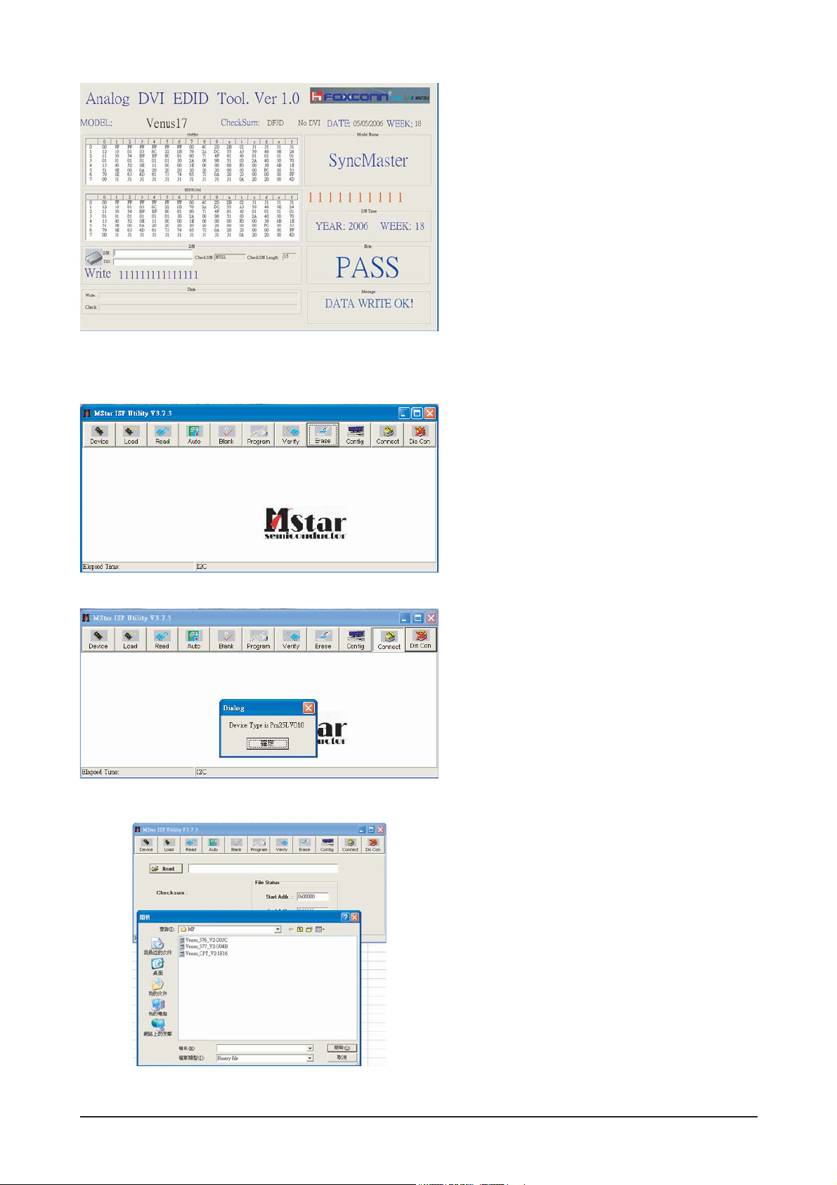
3-5 How to execute DDC
1. Install Analog DVI EDID Tool Program
2. Click the Analog DVI EDID Tool icon.
3. Select mode The password is 1234.
Select the manufacture is Venus and the model
name is Venus 17.
4.Setting
The password is 1234.
Select the port1and the SN Leng is 22.
Save the change.
5. Select Write-Auto Write
The SN number is a 22 random numbers.
3 Alignments and Adjustments
3-5
6. Write DDC ok.
1. Set the options.
-. Manufacture: MSTAR
-. Device Type: TSUM16_ROM128K_ext_flash
-. Communication Port: DSUB15 (Analog)
-. External Memory: PM25LV010E
2. Click 'Connect File' button, and select the
MCU code.
3. Click 'Read File' button, and select the MCU
code.
3-5 How to execute MCU Code
3 Alignments and Adjustments
3-6
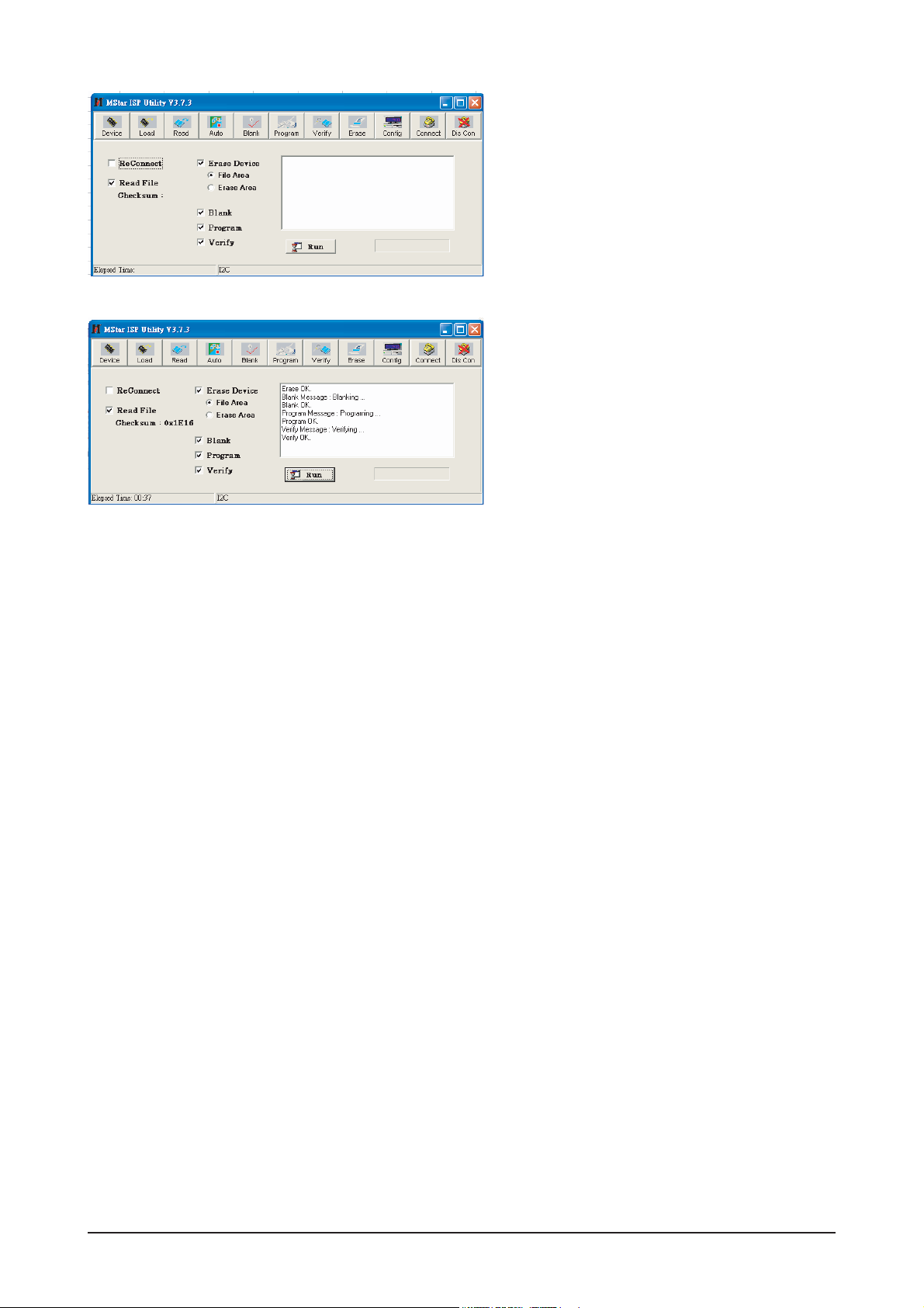
4. Click 'Auto Program' button.
5. If Program and Verify is OK, turn off the hard
power and than turn on again.

4 Troubleshooting
4-1
4 Troubleshooting
4-1 Common Acknowledge
- If you change the interface board, be sure that the U105, U106 and U103 these three components also
changed to the new I/F board because there was program inside. If not, please re-write EDID or upload
firmware into Flash memory via VGA Cable.
- If you adjust clock and phase, please do it at the condition of Windows shut down pattern.
- If you confirm the R.G.B. color is normal or not, please do it under 16-grey scalar pattern.
- This LCM is analog interface. So if the entire screen is an abnormal color that means the problem
happen in the analog circuit part, if only some scale appears abnormal color that stand the problem
happen in the digital circuit part.
- If you check the H/V position, please use the crosshatch pattern.
- This LCM support more than 30 timing modes, if the input timing mode is out of specification, the picture
may appears abnormally.
- If brightness uneven, repairs Inverter circuit or change a new panel.
- If you find the vertical line or horizontal line lost on the screen, please change panel.
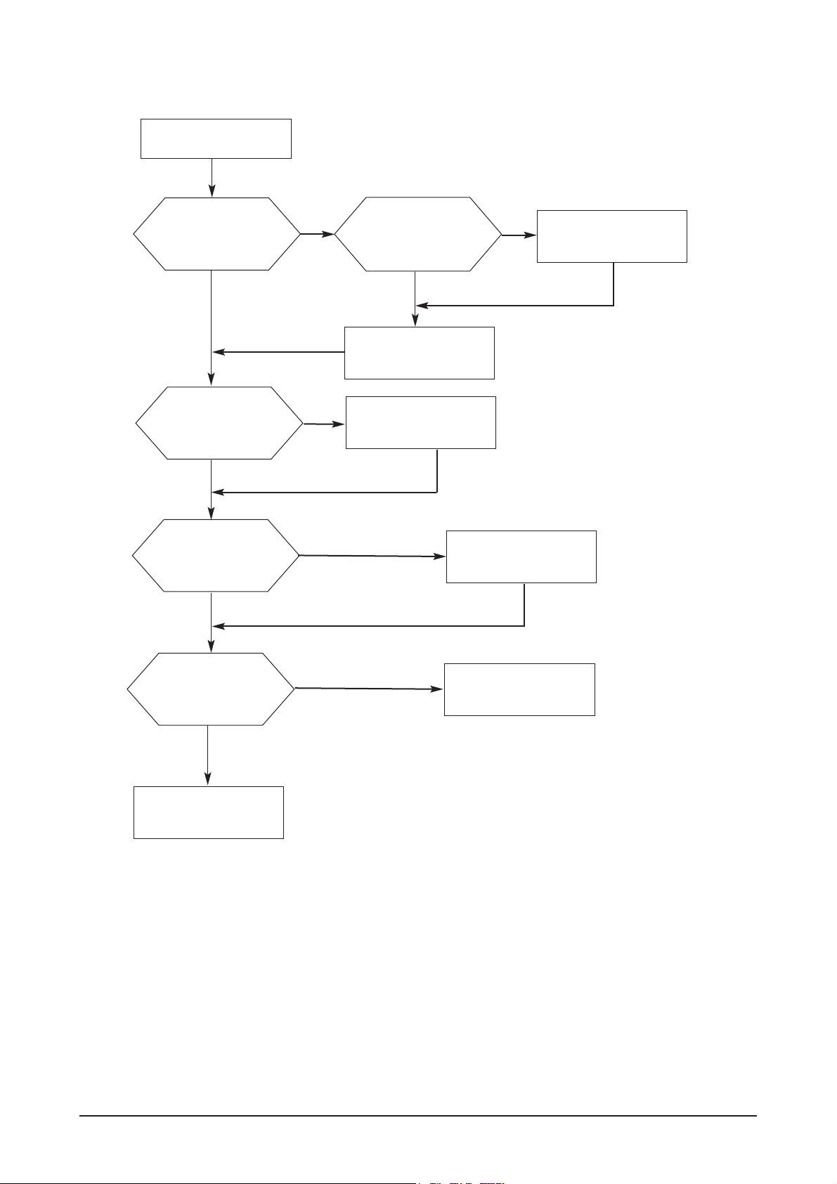
4 Troubleshooting
4-2
4-2 No Power & Power LED Off
Check primary
rectifier voltage
Check pin6 of
IC802 voltage
about 12V
Check pin2 of
IC802 voltage
about 3V
Check pin1 of
IC802 voltage is
voltage is below 1V
Check circuit if
short
No power
Check IC802,
C805, T801
Check F801, P801,
RT,801,D801
Check C810,D803,C807
Check primary OVP, OLP
and secondary feedback,
Check R811, R810,
R809, R808,R814
END
 Loading...