

Samsung 70 User Manual
No. 15 August 1998
Topic E and M Tielines
Introduction
• E&M Tielines are used to connect systems using E&M signalling
• E&M tielines allow connection between systems supporting E&M tielines and may be used for
intercom calls, transferring calls and LCR applications
• E&M tieline ports can only be connected other E&M Tieline ports
• E&M tielines take trunk port positions and may be accessed using direct trunk selection, accessing
a trunk group with the E&M tielines assigned or using LCR
• When an E&M Tieline is selected, dial tone is heard from the other system and DTMF can be sent
to the receiving E&M Tieline port to access features such as internal calls or accessing a trunk on
the remote system
• The Samsung DCS and the Samsung DCS 70 provide the option of using a translation table to
interpret the incoming digits to the E&M Tieline port on the DCS. The translation table can be used
in conjunction with LCR.
• Each E&M tieline card has four ports
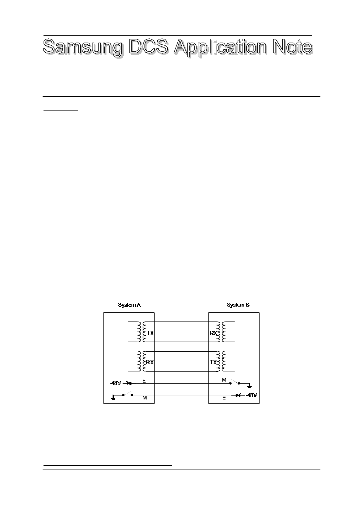
Note that a four wire E&M Tieline circuit has six wires associated with it. The numbering refers to the
number of wires used in speech circuits and not the E and M signalling wires.
Figure 1 Four Wire E&M Tieline Circuit as supported on Samsung DCS and DCS 70
Connecting two systems using E&M Tielines
Samsung DCS Application Note No 15 - Issue 01 Page 1 of 8
For Further Information Call LSP Communications

Connecting two systems using E&M Tielines can be done using three methods:
• Directly - if both systems are co-located
TX pair of system A is connected to the RX pair of system B
RX pair of system A is connected to the TX pair of system B
E lead of System A is connected to the M lead of system M
M lead of system A is connected to the E lead of system B
As per Figure 1 on Page 1
• Using Telstra Voicelink T - if network cable is required for connection
Cable the RX, TX, E lead and M lead to the MDF and tag them accordingly. Telstra then connect the
circuits to their Voicelink T circuits. Telstra connect the six wires to an interface that converts the
six wire circuit to two pairs using a cailho circuit and at the other end the two pair circuit is
converted to a six wire circuit for connection to System B
• Using Frame relay or some other form of multiplexing that supports E&M Tieline interfaces
Connection using Frame Relay or similar should be done in consultation with the multiplexer
installer/supplier. The cabling will involve using six wires.
Care should be taken to identify the leads as it is easy to become confused whether a pair tagged RX
on the multiplexer should be connected to the RX pair or the TX pair of the DCS or DCS 70. Similar
care should be taken when connecting the E lead and the M lead. Although it is unlikely damage
could be caused by incorrect connections, the E&M Tieline will only work if connected correctly.
Installation
• E&M Tieline cards must be installed in DCS systems with Version 5 or later software and the DCS
70
• E&M Tieline cards may be installed in any universal slot in any DCS cabinet
• E&M Tieline cards may be installed in any universal slot in the DCS 70
• The method used to install E&M Tieline cards is the same as installing other cards, the system
must powered off before installing or removing the cards
• If an E&M Tieline card is being added to an existing system, the procedures used are the same as
adding any other card.
+ Power Off
+ Insert the card in a vacant slot
+ Power On
+ Pre-install using MMC 806 after selecting the appropriate cabinet and slot then press right
hand soft key
+ Program the dial numbers in MMC 724
Tails and Connections
1. DCS 70
Samsung DCS Application Note No 15 - Issue 01 Page 2 of 8
For Further Information Call LSP Communications

The DCS 70 connects the E&M Tieline cards using tails and RJ45 connections. Ports 1 and 2
Ports
not used
not used
not used
not used
not used
RX2 Ring
TX2 Ring
RX1 Ring
on the cards are connected using the tails and ports 3 and 4 are connected using RJ45
connectors located on the cards.
Colour KSU(P2) EXP(P5) 4E&M
Card
Code Slot # Slot # Ports
1&2
White SLOT#1 SLOT#4 not used
W/Brown SLOT#1 SLOT#4 not used
White SLOT#1 SLOT#4 not used
Br/Slate SLOT#1 SLOT#4 not used
White SLOT#1 SLOT#4 RX2 Tip
W/Slate SLOT#1 SLOT#4 RX2 Ring
Yellow SLOT#1 SLOT#4 M 2
Blue SLOT#1 SLOT#4 E 2
Yellow SLOT#1 SLOT#4 TX2 Tip
Orange SLOT#1 SLOT#4 TX2 Ring
Yellow SLOT#1 SLOT#4 RX1 Tip
Green SLOT#1 SLOT#4 RX1 Ring
Yellow SLOT#1 SLOT#4 M 1
Brown SLOT#1 SLOT#4 E 1
Yellow SLOT#1 SLOT#4 TX1 Tip
Slate SLOT#1 SLOT#4 TX1 Ring
Colour KSU(P2) EXP(P5) 4E&M
Card
Code Slot # Slot #
1&2
White not used not used
Blue not used not used
White SLOT# 3 SLOT#6
Orange SLOT# 3 SLOT#6
White SLOT# 3 SLOT#6
Green SLOT# 3 SLOT#6
White SLOT# 3 SLOT#6 RX2 Tip
Brown SLOT# 3 SLOT#6
White SLOT# 3 SLOT#6 M 2
Slate SLOT# 3 SLOT#6 E 2
White SLOT# 3 SLOT#6 TX2 Tip
Wh/Blue SLOT# 3 SLOT#6
White SLOT# 3 SLOT#6 RX1 Tip
O/Blue SLOT# 3 SLOT#6
White SLOT# 3 SLOT#6 M 1
Gr/Blue SLOT# 3 SLOT#6 E 1
White SLOT# 3 SLOT#6 TX1 Tip
Br/Blue SLOT# 3 SLOT#6 RX1 Tip
not used
Colour KSU(P2) EXP(P5) 4E&M
Card
Code Slot # Slot # Ports
1&2
White SLOT#2 SLOT#5 not used
S/Blue SLOT#2 SLOT#5 not used
White SLOT#2 SLOT#5 not used
W/Orange SLOT#2 SLOT#5 not used
White SLOT#2 SLOT#5 RX2 Tip
O/Green SLOT#2 SLOT#5 RX2 Ring
White SLOT#2 SLOT#5 M 2
O/Brown SLOT#2 SLOT#5 E 2
White SLOT#2 SLOT#5 TX2 Tip
O/Slate SLOT#2 SLOT#5 TX2 Ring
White SLOT#2 SLOT#5 RX1 Tip
W/Green SLOT#2 SLOT#5 RX1 Ring
White SLOT#2 SLOT#5 M 1
Gr/Brown SLOT#2 SLOT#5 E 1
White SLOT#2 SLOT#5 TX1 Tip
Gr/Slate SLOT#2 SLOT#5 TX1 Ring
2. DCS
Samsung DCS Application Note No 15 - Issue 01 Page 3 of 8
For Further Information Call LSP Communications
 Loading...