

Page 1

4 CHANNEL DVR
User Manual
SDE-3001/3003
Page 2

4 Channel DVR
User Manual
Copyright
©2011 Samsung Techwin Co., Ltd. All rights reser ved.
Tra de mar k
The name of this product is the registered trademark of Samsung Techwin Co., Ltd.
Other trademarks mentioned in this manual are the registered trademark of their respective company.
Restriction
Samsung Techwin Co., Ltd shall reserve the copyright of this document. Under no circumstances, this document shall be reproduced,
distributed or changed, partially or wholly, without formal authorization of Samsung Techwin.
Disclaimer
Samsung Techwin makes the best to verify the integrity and correctness of the contents in this document, but no formal guarantee shall be
provided. Use of this document and the subsequent results shall be entirely on the user’s own responsibility. Samsung Techwin reserves the
right to change the contents of this document without prior notice.
Warra nty
If the product does not operate properly in normal conditions, please let us know. Samsung Techwin will resolve the problem for free of charge.
The warranty period is 3 years. However, the followings are excluded:
• Data loss due to a damaged hard disk
• If the system behaves abnormally because you run a program irrelevant to the system operation.
• Data loss due to virus infection
• Deteriorated per formance or natural worn-out in process of time
• Sensor y phenomenon that does not affect the performance or quality of the product (ex: working noise).
Design and specifications are subject to change without prior notice.
The default password can be exposed to a hacking thread so it is recommended to change the password af ter installing the
product.
Note that the security and other related issues caused by the unchanged password shall be responsible for the user.
is the registered logo of Samsung Techwin Co., Ltd.
Page 3
overview
IMPORTANT SAFETY INSTRUCTIONS
Read these operating instructions carefully before using the unit.
Follow all the safety instructions listed below.
Keep these operating instructions handy for future reference.
1) Read these instructions.
2) Keep these instructions.
3) Heed all warnings.
4) Follow all instructions.
5) Do not use this apparatus near water.
6) Clean only with dry cloth.
7) Do not block any ventilation openings, Install in accordance with the manufacturer’s instructions.
8) Do not install near any heat sources such as radiators, heat registers, stoves, or other
apparatus (including amplifiers) that produce heat.
9) Do not defeat the safety purpose of the polarized or grounding- type plug. A polarized plug has
two blades with one wider than the other. A grounding type plug has two blades and a third
grounding prong. The wide blade or the third prong are provided for your safety. if the provided
plug does not fit into your outlet, consult an electrician for replacement of the obsolete outlet.
10) Protect the power cord from being walked on or pinched particularly at plugs, convenience
receptacles, and the point where they exit from the apparatus.
11) Only use attachments/accessories specified by the manufacturer.
12) Use only with the cart, stand, tripod, bracket, or table specified by the
manufacturer, or sold with the apparatus. When a cart is used, use
caution when moving the cart/apparatus combination to avoid injury from
tip-over.
13) Unplug this apparatus during lightning storms or when unused for long
periods of time.
14) Refer all servicing to qualified service personnel. Servicing is required when the apparatus has
been damaged in any way, such as power-supply cord or plug is damaged, liquid has been
spilled or objects have fallen into the apparatus, the apparatus has been exposed to rain or
moisture, does not operate normally, or has been dropped.
OVERVIEW
English _3
Page 4
overview
CAUTION
RISK OF ELECTRIC SHOCK.
DO NOT OPEN
CAUTION
: TO REDUCE THE RISK OF ELECTRIC SHOCK, DO NOT REMOVE COVER (OR BACK) NO USER
SERVICEABLE PARTS INSIDE. REFER SERVICING TO QUALIFIED SERVICE PERSONNEL.
This symbol indicates that dangerous voltage consisting a risk of electric shock is present within
this unit.
This exclamation point symbol is intended to alert the user to the presence of important operating
and maintenance (servicing) instructions in the literature accompanying the appliance.
WARNING
• To reduce the risk of fire or electric shock, do not expose this appliance to rain or moisture.
• To prevent injury, this apparatus must be securely attached to the floor/wall in accordance with the installation
instructions.
WARNING
1. Be sure to use only the standard adapter that is specified in the specification sheet.
Using any other adapter could cause fire, electrical shock, or damage to the product.
2. Incorrectly connecting the power supply or replacing battery may cause explosion, fire, electric shock, or
damage to the product.
3. Do not connect multiple cameras to a single adapter. Exceeding the capacity may cause abnormal heat
generation or fire.
4. Securely plug the power cord into the power receptacle. Insecure connection may cause fire.
5. When installing the camera, fasten it securely and firmly. The fall of camera may cause personal injury.
6. Do not place conductive objects (e.g. screwdrivers, coins, metal parts, etc.) or containers filled with water on
top of the camera. Doing so may cause personal injury due to fire, electric shock, or falling objects.
7. Do not install the unit in humid, dusty, or sooty locations. Doing so may cause fire or electric shock.
8. If any unusual smells or smoke come from the unit, stop using the product. In such case, immediately
disconnect the power source and contact the service center. Continued use in such a condition may cause fire
or electric shock.
9. If this product fails to operate normally, contact the nearest service center. Never disassemble or modify this
product in any way. (SAMSUNG is not liable for problems caused by unauthorized modifications or attempted
repair.)
When cleaning, do not spray water directly onto parts of the product. Doing so may cause fire or electric shock.
10.
11. Do not expose the product to the direct airflow from an air conditioner.
Otherwise, it may cause moisture condensation inside the Clear Dome due to temperature difference between
internal and external of the dome camera.
12. If you install this product in a low-temp area such as inside a cold store, you must seal up the wiring pipe with
silicon, so that the external air can not flow inside the housing.
Otherwise, external high, humid air may flow inside the housing, pooling moisture or vapor inside the product
due to a difference between internal and external temperature.
4_ overview
Page 5
BEFORE START
This user manual provides Information for using the DVR such as brief introduction, part names, functions, connection
to other equipment, menu setup, etc.
You have to keep in mind the following notices :
• SAMSUNG retains the copyright on this manual.
• This manual cannot be copied without SAMSUNG’s prior written approval.
• We are not liable for any or all losses to the product incurred by your use of non-standard product or violation of
instructions mentioned in this manual.
• Prior to opening the case, please consult a qualified technician first. Whenever this is needed power must be
removed from the unit.
• Before installing an additional HDD or connecting an external storage device (USB memory or USB HDD) to this
DVR, check the compatibility. Consult your provider for the compatibility list.
Warning
❖ Battery
It is essential that when changing the battery in the unit, the replacement battery must be of the same type
otherwise there may be a possibility of an explosion.
The following are the specifications of the battery you are using now.
• Normal voltage : 3V
• Normal capacity : 170mAh
• Continuous standard load : 0.2mA
• Operating temperature : -20°C ~ +85°C
(-4°F ~ +185°F)
CALIFORNIA USA ONLY
This Perchlorate warning applies only to primary CR (Manganese Dioxide)
Lithium coin cells in the product sold or distributed ONLY in California USA.
“Perchlorate Material - special handling may apply,
See www.dtsc.ca.gov/hazardouswaste/perchlorate.”
OVERVIEW
Connect the power cord into a grounded outlet.
J
The Mains plug is used as a disconnect device and shall stay readily operable at any time.
Batteries shall not be exposed to excessive heat such as sunshine, fire or the like.
❖ System Shutdown
Turning off the power while the product is in operation, or undertaking improper actions may cause damage
or malfunction to the hard drive or the product.
Please turn off the power using the Power button on the front of your DVR.
After selecting <OK> in the pop-up menu, you can pull off the power cord.
You may want to install a UPS system for safe operation in order to prevent damage caused by an
unexpected power stoppage. (Any questions concerning UPS, consult your UPS retailer.)
❖ Operating Temperature
The guaranteed operating temperature range of this product is 0°C ~ 40°C (32°F ~ 104°F).
This product may not work properly if you run right after a long period of storage at a temperature below the
guaranteed one.
Prior to using a device that has been stored for a long period in low temperatures, allow the product to stand
at room temperature for a period.
Especially for the built-in HDD in the product, its guaranteed temperature range is 5°C ~ 55°C (41°F ~ 131°F).
Likewise, the hard drive may not work at a temperature below the guaranteed one.
English _5
Page 6

overview
CONTENTS
OVERVIEW
3
CONNECTING WITH
OTHER DEVICE
13
LIVE
21
3 Important Safety Instructions
5 Before Start
8 Features
10 Part Names and Functions
11 Part Names and Functions (Rear)
12 Remote Control
13 Installation
13 Checking the installation environment
14 Connecting the Video, Audio, and Monitor
14 Connecting the USB
15 Connecting the Camera
18 Connecting the Alarm Input/Output
19 Connecting the Network
21 Getting Started
23 Live Screen Configuration
27 Live Mode
29 Spot Out
29 Zoom
30 Audio ON/OFF
30 Freeze
30 Event Monitoring
(Front)
6_ overview
USING THE DVR
32
32 System Setup
42 Setting the Device
48 Setting the Recording
51 Setting the Event
54 Backup
55 Network Configuration
Page 7

SEARCH & PLAY
62
62 Search
65 Playback
WEB VIEWER
67
BACKUP VIEWER
88
APPENDIX
90
67 Introducing Web Viewer
68 Connecting Web Viewer
69 Using Live Viewer
73 Using Search Viewer
77 Viewer Setup
87 About
87 Mobile Viewer
88 SEC Backup Viewer
90 Product Specification (Camera)
92 Product Specification
94 Default Setting
97 Troubleshooting
99 Open Source License Report on the Product
OVERVIEW
English _7
Page 8

overview
FEATURES
The DVR employs H.264 video encoding for 4 channel inputs and audio encoding for 4 channels while simultaneously
supports hard disc recording and playback.
These DVRs also supports network connectivity, providing remote monitoring from a remote PC transferring video
and audio data.
• Provides a convenient User Interface
• 4 CH Composite Input Connectors
• Supports CIF(S)/2CIF(M)/4CIF(L) recording formats
• With the network specific codec, network transfer enabled regardless of the recording conditions
• De-interlacing processor for better picture quality
• Display of HDD information and status by using HDD SMART
• Hard Disk overwrite function
• Mass storage hard disk backup through high-speed USB 2.0
• Simultaneous Record and Playback of 4 channel video data
• Various Search Modes (Search by Time, Event, Backup and Motion Detection)
• Various Recording Modes (Time Lapse, Event, Scheduled Recording)
• Alarm Interface
• Remote Monitoring function by Network Viewer, Smart Viewer and Mobile Viewer
8_ overview
Page 9
Standards Approvals
This equipment has been tested and found to comply with the limits for a Class A digital device, pursuant to part 15
M
of the FCC Rules. These limits are designed to provide reasonable protection against harmful interference when the
equipment is operated in a commercial environment.
This equipment generates, uses, and can radiate radio frequency energy and, if not installed and used in accordance
with the instruction manual, may cause harmful interference to radio communications. Operation of this equipment
in a residential area is likely to cause harmful interference in which case the user will be required to correct the
interference at his own expense.
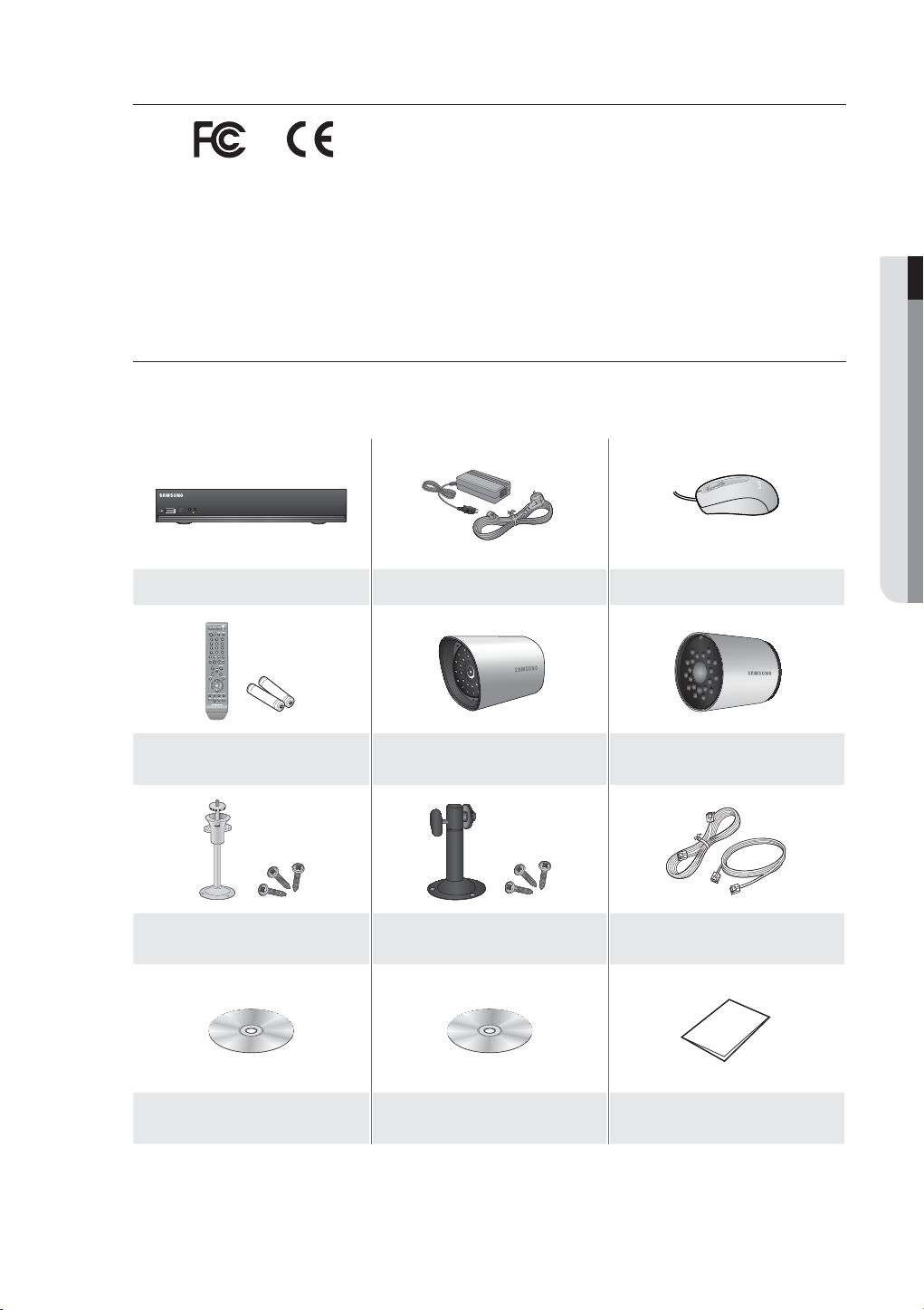
Package Contents
Please unwrap the product, and place the product on a flat place or in the place to be installed.
Please check the following contents are included in addition to the main unit.
OVERVIEW
POWER
REC
DIGITAL VIDEO RECORDER
DVR Adapter / Power Cable Mouse
Remote Control / Battery (AAA x 2)
SEB-1005R (Bracket 4EA, Screws 12EA)
Model : SDE-3003
SEB-1005R (4EA)
Model : SDE-3003
SEB-1007R (Bracket 4EA, Screws 12EA)
Model : SDE-3001
SEB-1007R (4EA)
Model : SDE-3001
Camera Cables(4EA), 18.3m (60ft) /
Network Cables
Network Viewer Software
User Manual CD,
Quick Connect Program CD
Quick Guide
English _9
Page 10
overview
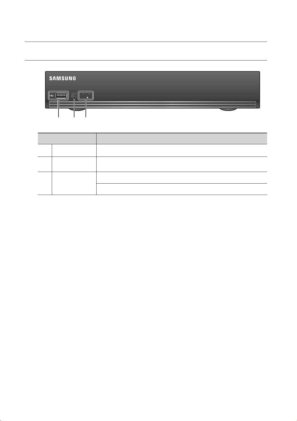
PART NAMES AND FUNCTIONS (FRONT)
POWER
REC
cb
Part Names Functions
USB Port Connects the USB devices.
DIGITAL VIDEO RECORDER
b
c
Remote Control
Receiver
LED Indicator
Input the remote control signal.
Power LED : Displays the power ON/OFF status.
REC : Lights on when recording is in progress.
10_ overview
Page 11
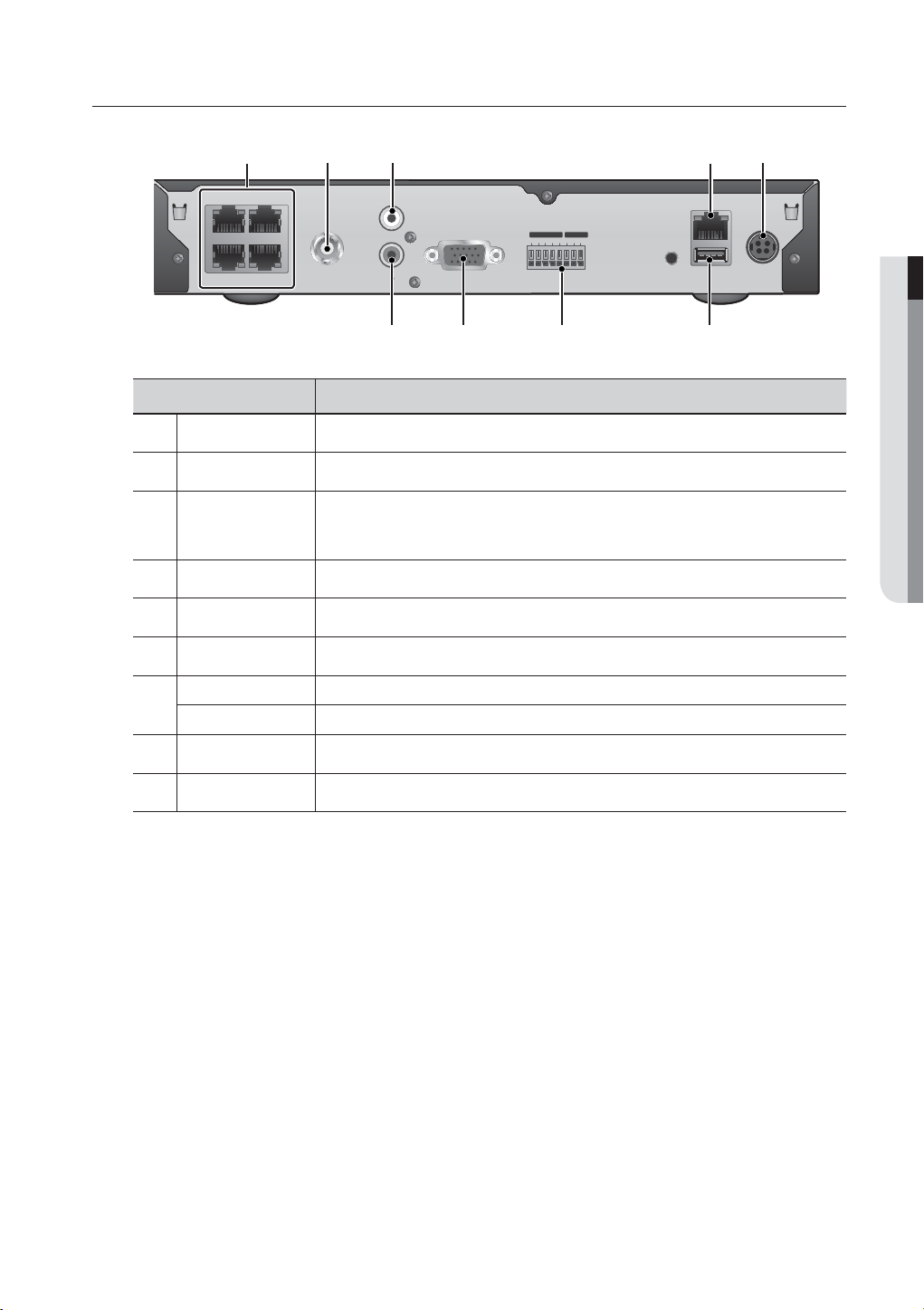
PART NAMES AND FUNCTIONS (REAR)
b c
12
34
Part Names Functions
CAMERA IN Video Signal input ports (UTP type connector).
VIDEO OUT Video Signal Output Port (RCA jack).
b
AUDIO IN
c
NETWORK NETWORK connector port.
DC 12V Camera and DVR power input port.
USB USB connector port.
ALARM IN 1~4, G : Alarm Input port.
ALARM OUT 1, COM : Alarm Output port.
VIDEO OUT
AUDIO IN
AUDIO OUT
Audio input signal port (
For SEB-1006R (MIC integrated camera), it is also recommended not to connect other
input devices to the AUDIO IN port.
VGA
RCA jack, CH1).
ALARM IN
ALARM OUT
1 2 3 4 G 1 COM G
CONSOLE
NETWORK
USB
DC 12V
OVERVIEW
VGA VGA Video Signal Output Port.
AUDIO OUT Audio Signal Output Port (RCA jack).
If using the VGA cable, the source from VGA will be displayed as main image on the screen along with the OSD
M
menus. Then, the BNC port will output the video signal alone.
If not using the VGA cable, the source from BNC will be displayed as main image on the screen along with the OSD
menus. If you connect the VGA cable after the system boot, only the video signal from VGA will be displayed.
English _11
Page 12
overview
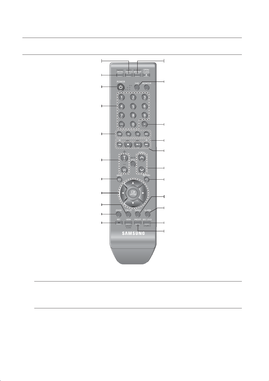
REMOTE CONTROL
Displays the search menu.
Changes the screen mode.
Displays the Exit pop up screen.
Used as the numeric input keys, or displays a single
Skip Backward (by unit time),
Slow Rewind, Slow Forward,
Skip Forward (by unit time)
Goes to the system menu screen.
Up/Down/Left/Right(▲▼◄ ►)/ENTER
Moves the cursor up/down/left/right, and runs the
Freezes the screen temporarily.
Runs the digital zoom (x2) function.
Starts or ends the live recording.
SEARCH
MODE
POWER
NUMBER [0~+10]
channel.
T/W
Zooms in or out.
MENU
Select Menu.
FREEZE
ZOOM
REC
BACKUP
Displays the Backup Menu.
DVR
Activates the DVR function.
ID
Sets the ID of the system.
Select 2 digits from 0 ~ 9 while pressing the ID Key.
Move Frame
While paused, moves to the previous/next frame.
FR, STOP, PLAY/PAUSE, FF
SCROLL ,.
Moves the menu scroll.
RETURN
Returns to the previous screen.
AUDIO
Turns Audio on/off.
ALARM
Cancels the Alarm.
REC LOCK
Selects the recording lock function.
PIP
Selects or deselects the PIP function.
EP10-000522
Using the Numeric buttons
1. Press any button among 1 to 4.
2. Move to the selected channel number.
Changing the Remote Control ID
1. Press the ID button of the remote control and check the ID displayed on the DVR screen.
The factory default ID of the remote control is 00.
2. Enter 2 digits of your selection in order, while pressing the system [ID] button.
3. When ID input is done, press the system [ID] button again to check the setting.
If you want to change the remote control ID to 08: Press 0 and 8 in order while the system [ID] button is pressed.
M
Remote control's ID and DVR’s ID should be matched for proper operation. Refer to “Remote Devices”. (Page 45)
12_ overview
Page 13
connecting with other device
INSTALLATION
Please take note of the followings before using this product.
• Do not use the product outdoor.
• Do not spill water or liquid in the connection part of the product.
• Do not impose the system to excessive shock or force.
• Do not pull out the power plug forcefully.
• Do not disassemble the product on your own.
• Do not exceed the rated input/output range.
• Use a certified power cord only.
• For the product with an input ground, use a grounded power plug.
CHECKING THE INSTALLATION ENVIRONMENT
CONNECTING WITH OTHER DEVICE
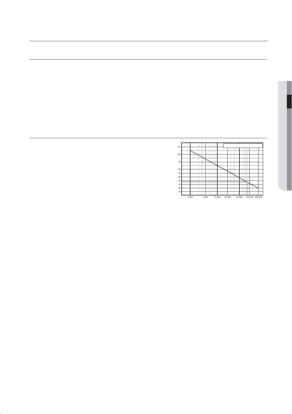
Samsung Digital Video Recorder (“DVR” hereinafter) is a
state-of-art security device, and contains mass storage hard
disk(s) and critical circuits inside.
When the temperature rises inside the product, the product
may breakdown and the product life be shortened.
Temperature
Unit: ºC
One Year: 24HR X 365 DAY =8,760 HR
Life (Unit: HOURS)
English _13
Page 14
connecting with other device
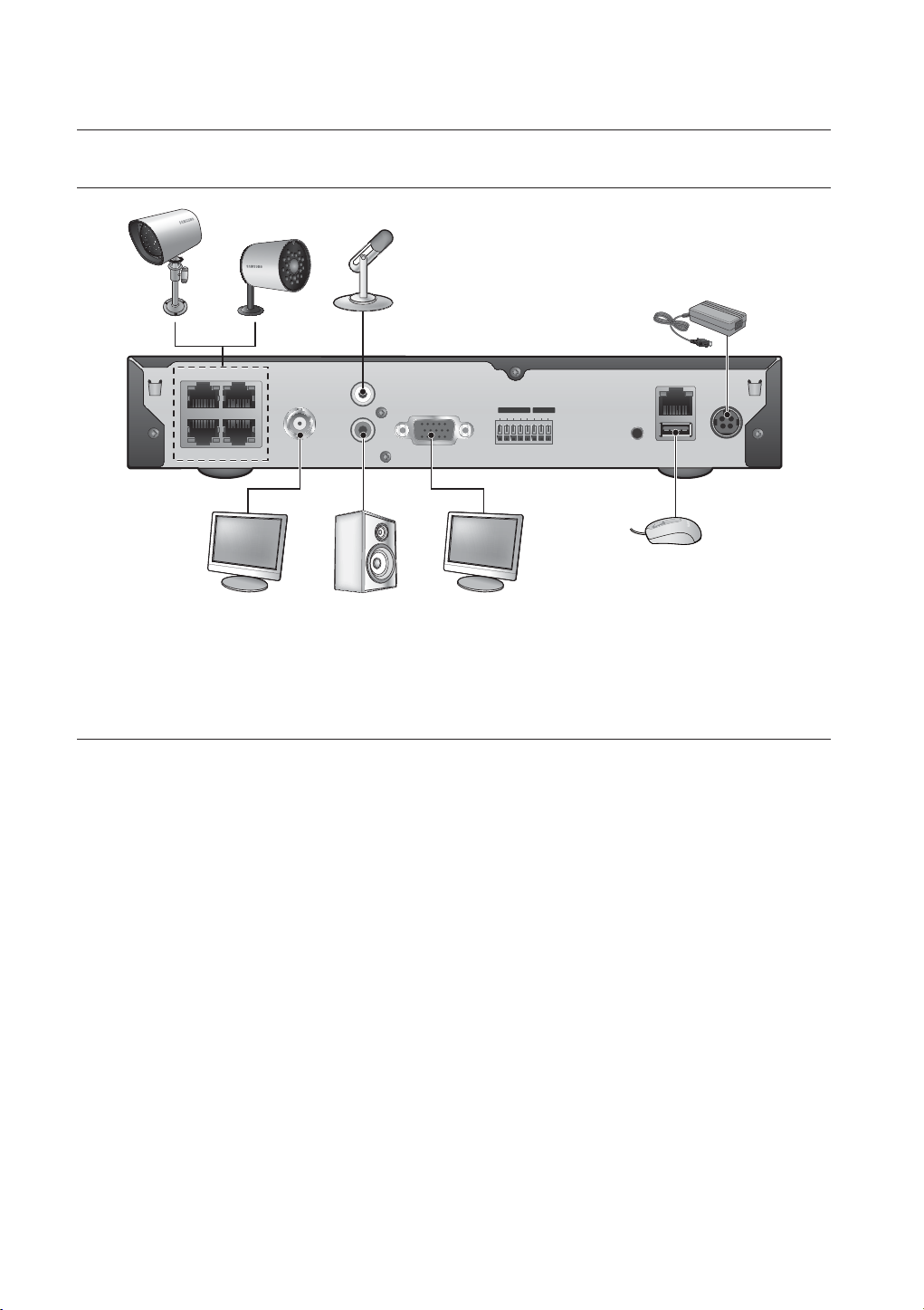
CONNECTING THE VIDEO, AUDIO, AND MONITOR
12
34
Only one mouse port is available.
M
VIDEO OUT
AUDIO IN
AUDIO OUT
NETWORK
ALARM OUT
ALARM IN
1234G1COMG
VGA
CONSOLE
DC 12V
USB
CONNECTING THE USB
1. By factory default, a USB port is provided for external connection.
2. You can connect a USB HDD, USB memory or mouse to the USB port.
3.
If a USB HDD is connected to the system, recognition and settings are available in “Menu > Setting the Device >
Storage Device”. (Page
4. This product supports hot-plugging, which connects/removes the USB device during the system operation.
43)
If you use the USB device for Backup purposes, format it with FAT32 on PC if it is not formatted on the DVR.
J
14_ connecting with other device
Page 15
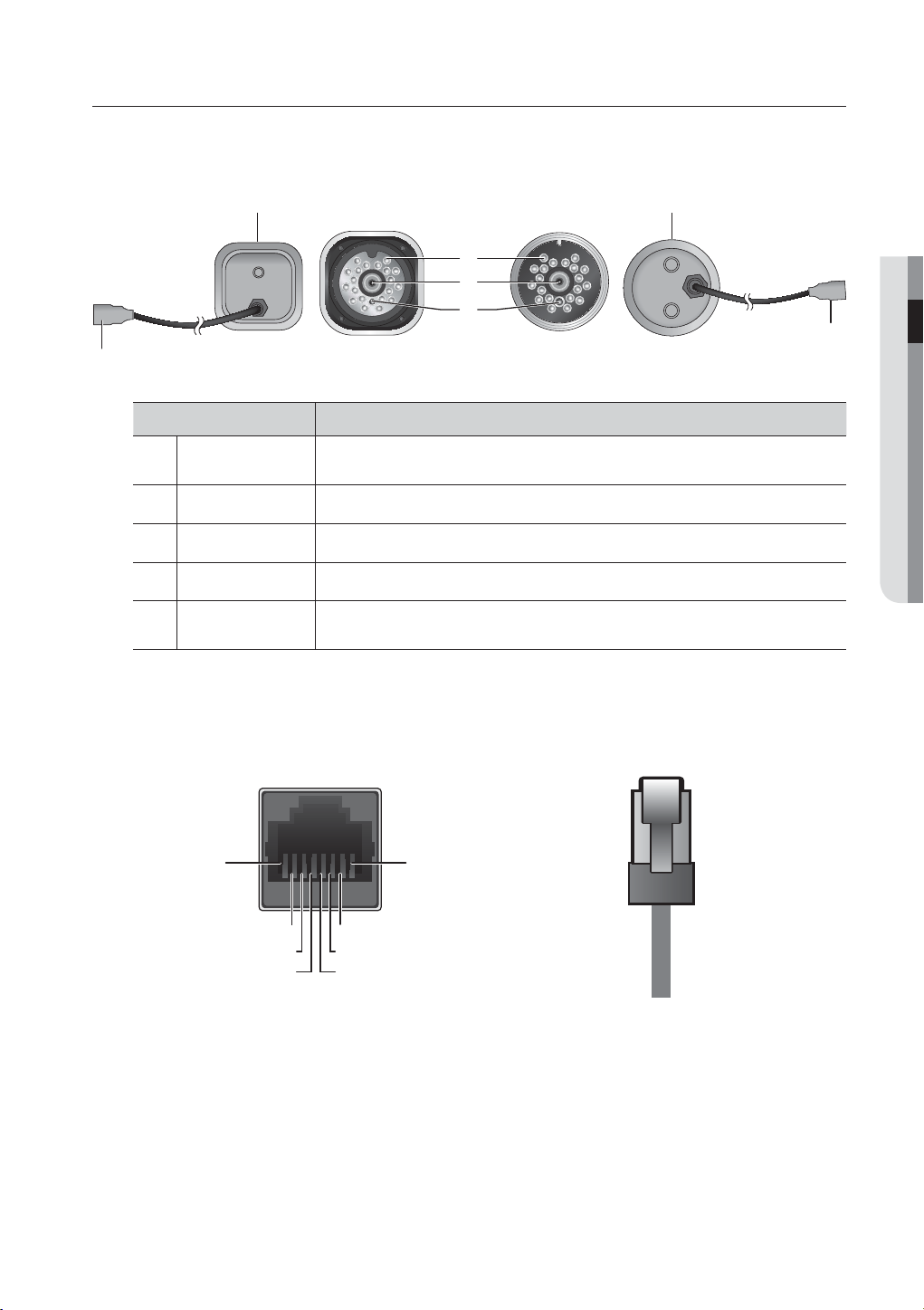
CONNECTING THE CAMERA
Equipped with the IR LED and the illumination sensor, enables you to monitor at night as well as in daytime.
The camera is suitable for both internal and external use.
Name Description
Camera Fitting
Groove
IR LED These infrared LED's are controlled by the illumination sensor.
b
Lens Focal length of 3.6mm enables you to cover relatively longer range of monitoring.
c
Illumination Sensor Detects incoming light to control the IR LED.
DVR Connection
Cable
Groove that is used to fit the camera bracket.
There are two grooves; one on the top and one on the bottom.
Connect the cable directly to the DVR without using a particular power cable.
You can use the RJ-45 cable to connect to a remote camera.
RJ-45 Cable (Length: 18.3m, 60ft)
b
c
SEB-1007RSEB-1005R
CONNECTING WITH OTHER DEVICE
This cable is specific to UTP connection, which is not compliant with the LAN cable. You can use the UTP
direct cable (all of 8 pins are used) to extend the length to a max of 200m. (based on UTP CAT 5e)
1. CVBS+
2. CVBS-
3. AUDIO
CVBS+
CVBS-
N.C
GND 12V
12V
GND
GND(AUDIO)
4. GND
5. 12V
6. N.C
7. N.C
8. N.C
<Cable pin information provided>
English _15
Page 16

connecting with other device
Installing the camera
The camera can be installed on the wall, ceiling, shelf or a desired position using the provided bracket.
1. Select a position where you want to install the
camera.
Make sure the selected position can sustain the
weight of the camera.
2. Use the screw bolts (M4 X L15) to mount the
camera bracket onto the wall or ceiling.
3. Place the camera on the selected position and fit
the hole either on the top or the bottom of the
camera into the fixing bolt of the bracket, and
turn the camera clockwise.
M4 X L15 sized
screws
wall or ceiling
wall or ceiling
M4 X L15
sized screws
You should be careful when installing the BOX
J
camera outdoors because the cable connectors
may be wet with moisture or pile up with impurities.
Camera Bracket
The camera bracket can be used to install the camera on the wall, ceiling or shelf.
Camera Bracket Specification
SEB-1007RSEB-1005R
Description
Use
Name
SEB-1005R SEB-1007R
Indoor
SEB-1007RSEB-1005R
Installation
Dimensions
Weight
Operating Temperature
Accessories
Wall or Ceiling
57(W) X 47.2(H) X 100.5(L) mm/
2.25(W) X 1.86(H) X 3.95(L) inch
130g(0.29 lbs) 55g (0.12 lbs)
-10˚C ~ 50˚C (14˚F ~ 122˚F)
SCREW (M4 X L15) : 3 pcs
16_ connecting with other device
40(W) X 58(H) X 40(D) mm/
1.57(W) X 2.28(H) X 1.57(D) inch
Page 17
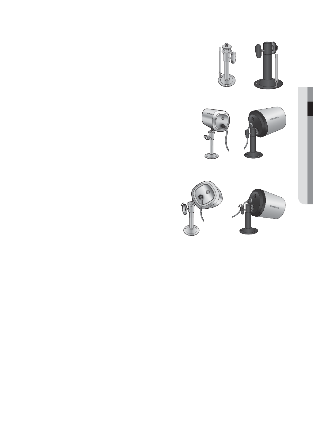
Adjusting the Camera Bracket
1. Choose an installation site that can sufficiently support the weight of
the equipments to be installed.
2. Attach the camera bracket to the wall using the supplied screws
(M4 X L15). 4x15 sized screws wall or ceiling.
3. Adjust the camera to target the video location and tighten the
camera bracket handle on the camera bracket. Install the camera
on to the male screw of the camera bracket by rotating the
camera clockwise.
4. Loosen the handle by turning it counter clockwise
and then adjust the camera position. Tighten the
handle, turning it clockwise to lock the camera in
position.
5. Connect the camera cable to the camera.
Handle
CONNECTING WITH OTHER DEVICE
Handle
English _17
Page 18
connecting with other device
1234G1COMG
ALARM IN
NETWORK
USB
CONSOLE
VGA
IN
UT
DC 12V
ALARM OUT
U
CONSO
A
1
234
G
G1CO
A
OUT
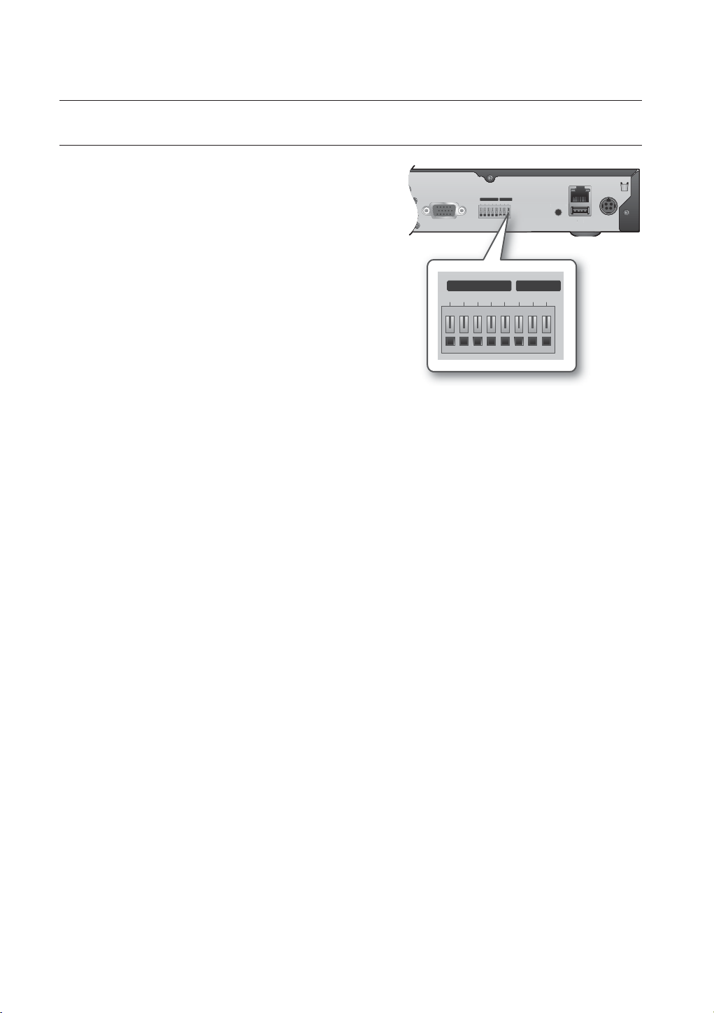
CONNECTING THE ALARM INPUT/OUTPUT
Connecting the alarm input signal
Connection port for the alarm input signal.
Connect one strand of the sensor signal line (four strands) to
the alarm input port and connect the other to the [G] port.
Connecting the alarm output signal
Connection port for the alarm output signal.
Connect one strand of the sensor signal line to the alarm
output port and connect the other to the [COM] port.
• ALARM IN : 5mA sink
• ALARM OUT : 24V DC 1A, 125VAC/0.5A
VG
ALARM IN
ALARM IN
LARM IN
1234G1COMG
1234GG1COM
ALARM OUT
ALARM OUT
ALARM
LE
SB
M
18_ connecting with other device
Page 19
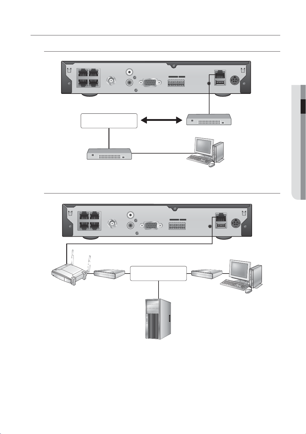
CONNECTING THE NETWORK
Connecting to Network through Ethernet (10/100BaseT)
12
34
NETWORK
Hub/Switcher
Connecting to the
12
34
AUDIO IN
ALARM IN
ALARM OUT
1 2 3 4 G 1 COMG
VIDEO OUT
AUDIO OUT
VGA
Back Bone
Network using the router
AUDIO IN
ALARM IN
ALARM OUT
1 2 3 4 G 1 COMG
VIDEO OUT
AUDIO OUT
VGA
CONSOLE
RJ-45 Ethernet Cable
(Direct Cable)
Hub/Switcher
CONSOLE
NETWORK
USB
NETWORK
USB
DC 12V
CONNECTING WITH OTHER DEVICE
Windows
Network Viewer
DC 12V
Broadband Router
xDSL or Cable
Modem
NETWORK
xDSL or Cable
Modem
External Remote PC
DDNS Server
(Data Center)
English _19
Page 20
connecting with other device
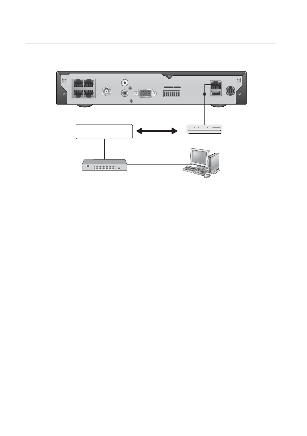
Connecting to Internet through ADSL
12
34
INTERNET
Hub/Switcher
VIDEO OUT
AUDIO IN
AUDIO OUT
ALARM IN
1 2 3 4 G 1 COMG
VGA
Phone(ADSL) Line
ALARM OUT
CONSOLE
RJ-45 Ethernet Cable
(Direct Cable)
ADSL MODEM
NETWORK
USB
DC 12V
Windows
Network Viewer
20_ connecting with other device
Page 21
live
GETTING STARTED
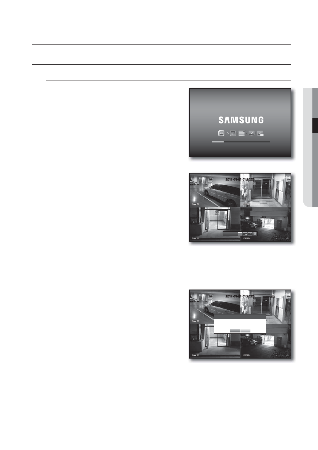
Starting the system
1. Connect the power cable of the DVR to the wall outlet.
It takes about 10 seconds to display the start screen after
M
booting.
2. You will see the initialization screen.
The initialization process will last about 1 minute.
If a new HDD is installed, the initialization process may take
longer.
3. The live screen appears with a beep.
Shutting Down the System
2011-01-01 01:10:25
2011-01-01
01:10:25
LIVE
REC
You can shut down the system only if you have logged into the DVR.
You require permission to shut down the system if you are not logged in as admin.
1. Press the [POWER] button on the remote control or
right-click to display the context sensitive menu and select
<Shutdown>.
2. The “Shutdown” confirmation window appears.
3. Use the arrow keys on the remote control to move to
<OK> and press the [ENTER] button or click <OK>.
The system will shut down.
4. Disconnecting the power cable for power off and
reconnecting the power cable to restart.
For the permission management, refer to “Permission Management > Setting Permissions”. (Page 37)
M
2011-01-01 01:10:25
Shutdown
Are you sure to shutdown?
OK Cancel
English _21
Page 22
live
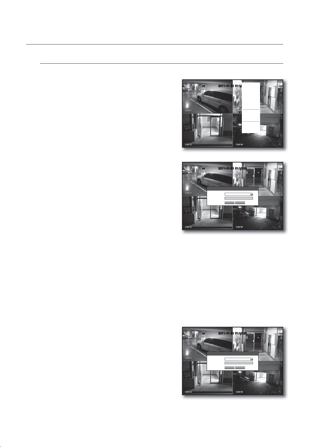
Login
To access a DVR or restricted menu, you should have logged in to the DVR.
1. In live mode, right-click any area of the screen.
You will see the context sensitive menu as in the right
figure.
2011-01-01 01:10:25
Scene Mode
Spot Out
Audio Off
Freeze
Stop Alarm
Record
Play
Search
Backup
Main Menu
Shutdown
Hide Launcher
Login
2. Click <Login>.
The login dialog appears.
You can also see the login dialog to access a desired menu
by pressing the [MENU] button on the remote control.
The login dialog will also appear if you press a menu button on
the remote control of the DVR when the corresponding menu
requires logging in.
After logged in, press [RETURN] on the remote control to display
the logout dialog.
By default, initial ID and password are set to “admin”, and
“4321”.
The default password can be exposed to a hacking thread so it is recommended to change the password after
J
installing the product.
Note that the security and other related issues caused by the unchanged password shall be responsible for the user.
For the restricted permission, refer to “Permission Management > Setting Permissions”. (Page 37)
M
Locking All Buttons
This will restrict access to all buttons available in the DVR.
1. In Live mode, press buttons in the order of [STOP (@)]
[FREEZE][STOP (@)][FREEZE][MENU].
All buttons will be locked.
2. In the lock condition, press any button to display a dialog
where you are prompted to enter the password for
unlocking the buttons.
The button lock will be released if you enter the admin
password.
2011-01-01 01:10:25
Login
ID admin
Password
OK Cancel
2011-01-01 01:10:25
Key Lock Password
ID admin
Password
OK Cancel
22_ live
Page 23
LIVE SCREEN CONFIGURATION
CAM 01
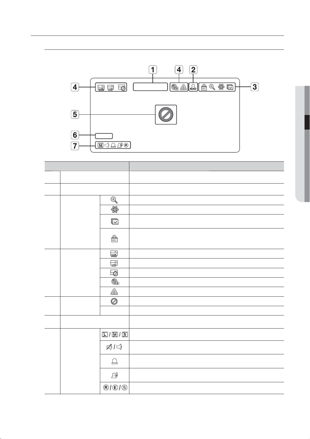
Icons on the Live Screen
You can check the status or operation of the DVR with the icons on the live screen.
b
c
System Operation
Video Input Status
2011-01-01 00:00:01
CAM 01
Name Description
Current Date, Time
Login Information
Screen Mode
Displays the current time and date.
When you are logged in, the “LOG ON” icon will be displayed.
Displayed if the zoom function is activated.
Displayed if you press the Pause button.
Displayed in Auto Sequence mode where all channels are switched at the
specific time interval.
This icon is displayed if a user with restricted access to the Record button tries
to make manual recording.
Only the user with the applicable permission can release (stop) the recording.
Displayed if the HDD is full and the DVR has an insufficient space to record.
Displayed if no HDD is installed or the existing HDD should be replaced.
Displayed if the HDD needs a technical examination.
This will be displayed if the backup operation is in process.
Displayed if a new firmware is found from the network.
Displayed if no input is entered in the condition that the camera is set to <ON>.
Nothing will be displayed on the screen if the camera is set to <OFF>.
LIVE
Camera Name/ Channel
Camera Operation
Displays the camera name and the changed channel, if any.
Displays the resolution of the recording screen. (Page 49)
Displays AUDIO ON/MUTE.
Not displayed in video mode if deactivated.
If the sensor is set to <ON>, the input signal will be displayed on the screen of
the connected channel.
Displayed if a motion detected in the condition that the motion detection is set to
<ON>.
Displays the current record mode from Record/Event/Schedule.
English _23
Page 24
live
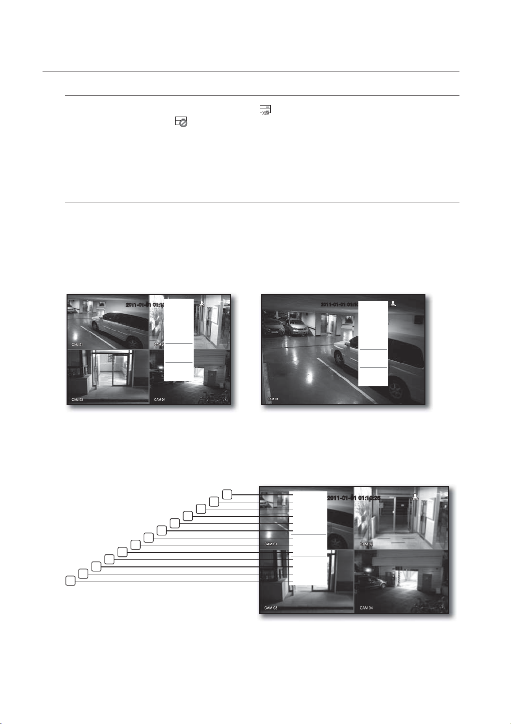
Error Information
• If the internal HDD is not connected, the “NO HDD”( ) message will appear; if there occurs a problem,
you will see the “HDD FAIL”(
service center for assistance as this may cause a failure of recording, playback or backup.
If you see the No HDD, HDD FAIL icons on the screen, contact the service center for more details.
M
Live Screen Menu
In addition to the buttons the remote control, you can access a desired menu by right-clicking the mouse any
area in live mode.
The context sensitive menu that appears by right-clicking the screen may differ, depending on the login/
logout, screen split mode and DVD operation mode.
Menu items of Search, Record, Backup, Shutdown can be deactivated, depending on the user permission.
M
2011-01-01 01:10:25
) message in the top left corner. In this case, make sure you contact the
Scene Mode
Spot Out
Audio Off
Freeze
Stop Alarm
Record
Play
Search
Backup
Main Menu
Shutdown
Hide Launcher
Logout
2011-01-01 01:10:25
Scene Mode
Spot Out
Zoom In
Audio
Freeze
Stop Alarm
Record
Play
Search
Backup
Main Menu
Shutdown
Hide Launcher
Logout
< Split Mode Menu >
< Single Mode Menu >
Split Mode Menu
The context sensitive menu in split mode differs, depending on the login/logout status.
Scene Mode
Spot Out
Audio Off
Freeze
Stop Alarm
Record
Play
Search
Backup
Main Menu
Shutdown
Hide Launcher
Logout
2011-01-01 01:10:25
13
24_ live
12
11
10
1
2
3
4
5
6
7
8
9
Page 25
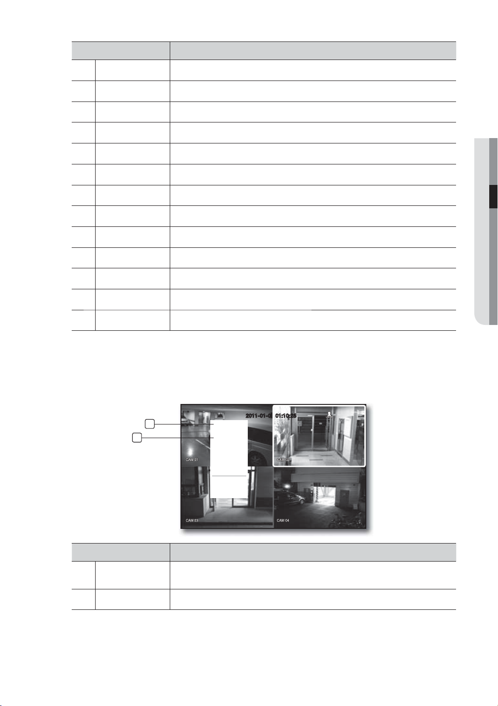
Menu Description
Scene Mode Refer to “Live Mode”. (Page 27)
Spot Out Refer to “Spot Out”. (Page 29)
b
Audio On/Off Refer to “Audio ON/OFF”. (Page 30)
c
Freeze Refer to “Freeze”. (Page 30)
Stop Alarm Stops the alarm output and the event monitoring. Refer to “Event Monitoring”. (Page 30)
Record/Stop Starts/stops the standard recording.
Play Refer to “Search & Play > Play”. (Page 65)
Search Refer to “Search & Play > Search”. (Page 62)
Backup Refer to “Using the DVR > Setting the Backup”. (Page 54)
Main Menu Accesses the main menu. Refer to the Using the DVR section. (Page 32)
LIVE
Shutdown
Show/Hide Launcher
Login/Logout You can log in or out.
m
Turns down the DVR.
Shows or hides the launcher. Refer to “View the Launcher Menu”. (Page 26)
Single Mode Menu
The single mode menu is available only in Single Mode.
The context sensitive menu for the One Channel mode, in Split mode is different from that of the Single mode.
1
2
Menu Description
Full Screen
Spot Out
Zoom In
Audio
Freeze
Stop Alarm
Record
Play
Shutdown
Hide Launcher
Logout
2011-01-01 01:10:25
b
Full Screen
Zoom In
Select and click a desired channel in Split mode to switch to the full screen of the selected
channel.
Enlarges the selected image. (Page 29)
English _25
Page 26
live
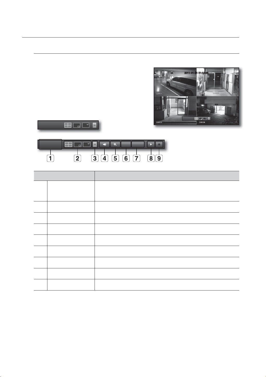
View the Launcher Menu
The Launcher menu appears on the bottom of the live screen.
1. In Live mode, right-click to display the context menu and
select <Show Launcher>.
2. Move the cursor to the bottom and click a desired item in
the Launcher menu.
If no input is entered for 10 seconds, the menu will disappear.
M
The Launcher menu can be accessed only by using the mouse.
2011-01-01
01:10:25
2011-01-01 01:10:25
2011-01-01
01:10:25
2011-01-01
01:10:25
Menu Description
Date/Time
Screen Mode Press this button to switch the screen mode in sequence.
b
Menu Expansion Button Click to display the hidden menu to the right.
c
Audio Turns ON/MUTE the sound of the selected channel.
Zoom Enlarges the selected area. This is available only in Single Live mode.
Alarm Stops the alarm if it's activated.
Freeze Freezes the Live screen temporarily.
Play Enters Play mode if a file to play exist, and if not, enters Search mode.
Record Start/End recording the Live screen.
Displays the current time and date.
The indication of AM/PM is displayed if you set 12 hours for the time format in
“System > Date/Time/Language > Time”. (Page 32)
Alarm Freeze
26_ live
Page 27
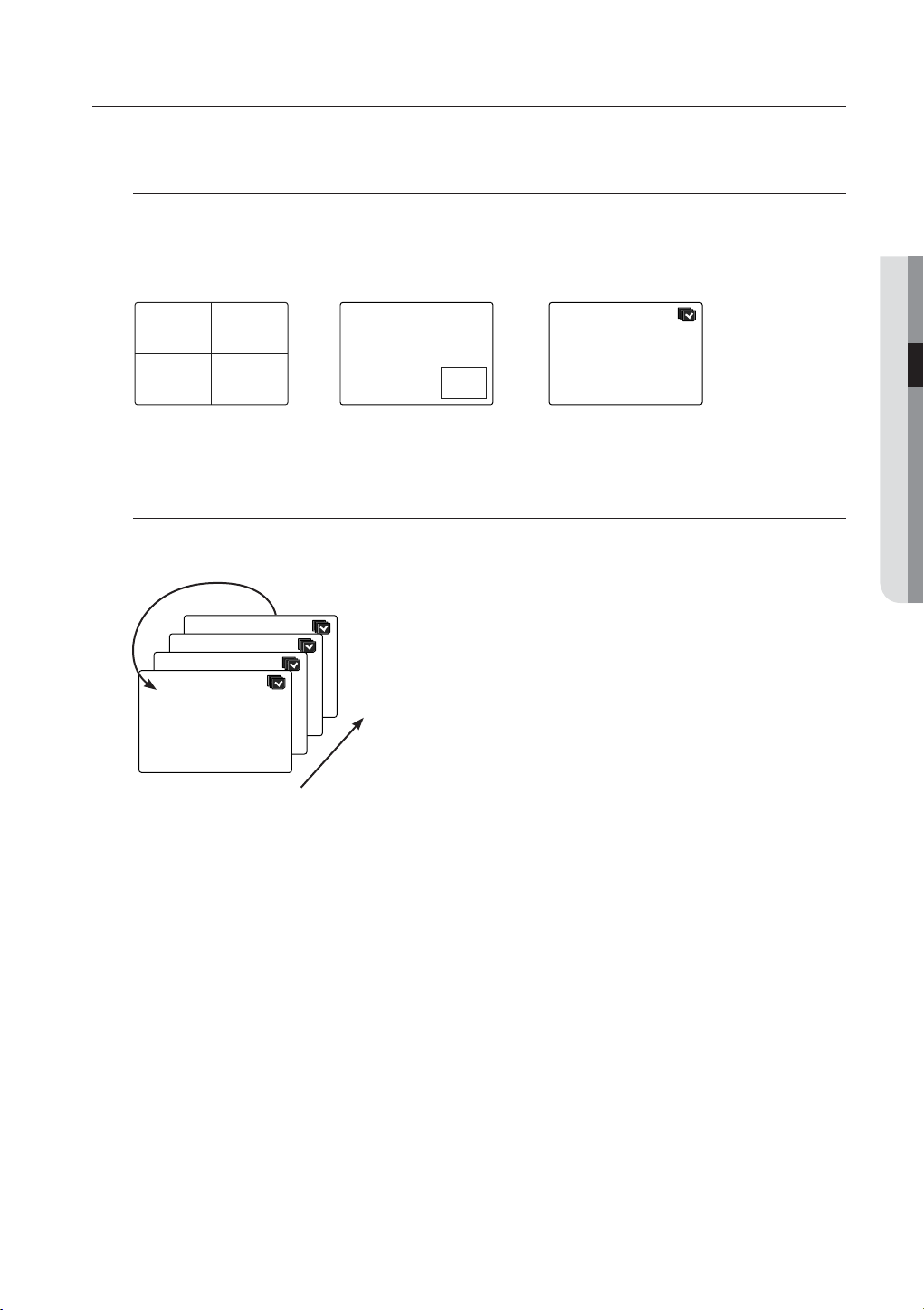
LIVE MODE
Displays 4 live video images in 3 different modes.
Switching the screen mode
To switch the split mode, select a screen mode in the launcher menu, or right-click to select a screen mode in
the context menu.
Press the [MODE] button
items.
CH1 CH2
CH3 CH4 CH1
4-split mode PIP Auto Sequence
Switching the screen automatically
With SDE-3001/3003 you can display 4 live single screens in sequence.
on the remote control to switch the mode in the sequence of the launcher menu
CH2
CH1
LIVE
CH1
CH1
CH1
CH1
Single mode
In Single mode, If you have set <SEQ-Dwell Time> in “Setting the Device > Camera”, Auto Sequence will be
M
conducted at the set interval. (Page 42)
1
4
English _27
Page 28

live
Channel Setting
You can display the channel in a desired area of a split screen.
1. Click a camera name to display a channel list where you can select a different channel.
2. Select a desired channel and click it.
The current channel will be switched to the selected one.
Use the cursor to select a channel to move, and drag and drop it to a desired channel; this can also
change the channel position.
Ex : if switching CH 1 to CH 4
CH1 CH2
CH4 CH2
CH3 CH4
Switching to Single Mode
When in split mode, select and double-click a desired channel to switch to its Single mode.
Press the number corresponding to a desired channel the remote control to switch to its Single mode.
Refer to “Remote Control > Using the numeric buttons”. (Page 12)
Ex : If double-clicking CH 3 or pressing the number “3” on the remote control.
CH1 CH2
CH3 CH1
CH3 CH4
CH3
28_ live
Page 29

SPOT OUT
The Spot Out monitoring is independent of the Live mode, which monitors a specific channel through the Spot Out
port.
Selecting a Spot Out mode
If an event occurs such as sensor, motion or alarm from the Spot Out port in connection with a monitor, you
can select a output screen mode.
1. In Live mode, right-click any area on the screen.
The Live menu appears.
2. Click Spot Out.
Supports the Spot output in Single screen with Auto
Sequence mode.
The Spot output is supported only for a designated channel.
For the Spot Out port of a model, refer to “Part Names and
Functions (Rear)”. (Page 11)
Scene Mode
2011-01-01 01:10:25
Spot Out
Auto Sequence
Audio Off
CH1
CH2
Freeze
CH3
Stop Alarm
CH4
Record
Play
Search
Backup
Main Menu
Shutdown
Hide Launcher
Logout
< Multichannel Live Menu >
ZOOM
LIVE
This is available only in Single Live mode. In Single mode, select a desired area and use the Zoom function to
enlarge it twice.
1. Select <Zoom In> in the right-click menu.
Press the [ZOOM] button
on the remote control, or simply click < > in the launcher menu. The zoom
box appears.
2. Use the direction keys, or drag and drop to specify an area to enlarge.
3. Press the [ENTER] button, or double-click the selected area to enlarge it twice.
In the enlarged image, use the direction buttons (◄ ►) on the remote controlto move the enlarged area.
4. Press the [ZOOM] button on the remote control, or simply click < > in the launcher menu to release
the zoom.
2011-01-01 01:10:25
English _29
Page 30
live
AUDIO ON/OFF
You can turn the sound on/off corresponding to the channel in Live mode.
AUDIO ON/OFF in Single mode
Click the audio icon ( ) on the screen, or press the [AUDIO] button on the remote control to turn it on/off.
Only the channel where <AUDIO> is set to <ON> in “Device > Camera” displays the audio icon ( ) in Live mode
M
that you can use to turn the sound on/off.
FREEZE
This is available only in Live mode, this pauses playing the Live image temporarily.
>.
Freeze
> in the launcher menu.
1. Press the [FREEZE] button the remote control, or click <
The playback of the image is stopped temporarily.
2. Press the [FREEZE] button again, or click <
This will release the freeze.
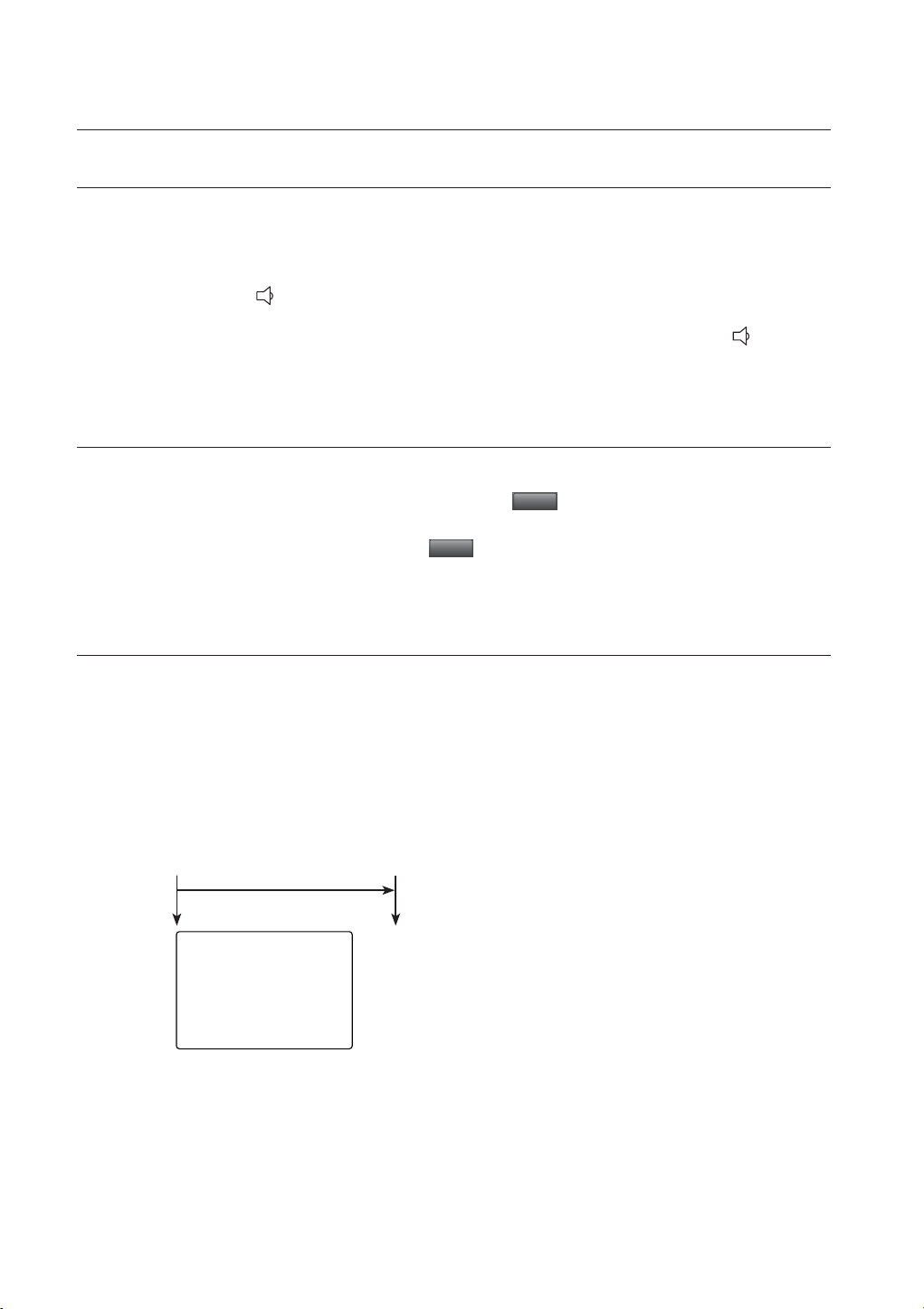
EVENT MONITORING
Freeze
This will display the channel in sync with a specific event (Sensor/Motion/Video Loss) if it occurs.
In “Monitor > Event Display”, set the event monitoring to ON/OFF and specify the event display time. (Page
• If multiple events occur simultaneously, the screen will switch to a split mode.
- 2~4 events : 4-split mode
• If the second event occurs within the set time of <Event Display>, the first event will last until the second
one is terminated. (Page
Ex : If you set <Event Display> to 5 seconds, and only one event occurs in CH 1.
Event occurrence 5 seconds
CH1
46)
Stop alarm
46)
30_ live
Page 31

Ex : If you set <Event Display> to 5 seconds, and the second event occurs in CH 2 within the set time after the first
event occurred in CH 1.
Event occurrence 4 seconds 9 seconds
Stop alarm
CH1 CH2
CH1
Press the [ALARM] button to reset the alarm settings and to release the event mode.
M
If an alarm activates in the condition you have set the event record, and pre/post alarm times, the event record will
be performed.
LIVE
English _31
Page 32

using the DVR
You can setup the system properties, devices, and options for recording, event,
backup and network.
SYSTEM SETUP
You can setup Date/Time/Language, Permission, System Properties and Log.
Date/Time/Language
You can check and setup the current Date/Time and time related properties, as well as the language used for
the interface on the screen.
Setting the Date/Time/Language
Set the Date/Time/Language
Using the mouse may help make setup easier.
1. Press the [MENU] button on the remote control.
If not logged in, it prompts with login window.
Refer to “Login”. (Page 22)
2011-01-01 01:10:25
2011-01-01
01:10:25
2. Use the left/right buttons (
◄ ►
) to select the <System>.
System property setup menu is selected.
3. Use the up/down buttons (
Language> and press the [ENTER] button.
4. Select <Date/Time/Language>.
A dialog to setup Date, Time and Language.
5. Use direction buttons (
◄ ►
) to select <Date/Time/
) to select an item to set
System
Date/Time/Language
Permission Management
System Management
Log Information
and make your changes.
• Date : Sets the date that will appear on the screen.
You can select the date format.
• Time : Sets the time and its format that will appear on the
screen.
Select either one from <24 Hours, 12 Hours (AM/PM)>.
• Time Zone : Sets the time zone of your area based on the
Greenwich Mean Time (GMT).
GMT (Greenwich Mean Time) is standard World Time and the basis
of world time zone.
Date/Time/Language
Date/Time/Language
Date 2011-01-01 YYYY-MM-DD
Time 08:14:24 24 Hours
Time Zone GMT
Time Sync.
DST
Language English
Holiday
+09:00
Setup
Dec First (Sun) 0 Dec First (Sun) 0
OK Cancel
• Time Sync. : You can set the DVR’s current time
synchronized to a selected <Time Server> regularly if you select to use <Time Server>.
In this case, <Date/Time/Language> setup does not allow time adjustment.
Logout
Return
32_ using the DVR
Page 33

- Time Server : Enter an IP or URL address of the time
server.
- Last Sync Time : Displays the most recent
synchronization time from the selected time server.
- Activate as Server : Set to <Use> to allow the DVR to act
as a Time Server for other DVRs.
• DST : Set up Daylight Saving Time with its period to make
the time earlier than the GMT of its time zone by 1 hour
during the set period.
• Language : Select your language. Sets the language for the
Date/Time/Language
Date/Time/Language
Date 2011 -01-01 YYYY-MM-DD
Time Synchronization Setup
Synchronization Use
Time 08:14:24 24 Hours
Time Server 203.248.240.103
Time Zone GMT+08:00
Last Sync Time Fail
Time Sync.
Activate as Server Use
DST
Language English
Holiday
Setup Not Used
Dec First (Sun) 0H Dec First (Sun) 0H
OK Cancel
OK Cancel
interface.
English, French, German, Spanish, Italian, Chinese, Russian, Korean, Polish, Japanese, Dutch, Portuguese,
Turkish, Czech, Danish, Swedish, Thai, Romanian, Serbian, Croatian, Hungarian and Greek are available.
6. When the Date/Time/Language setup is done, press <OK>.
You can also use numeric buttons on the remote control to enter values for Date, Time and other numeric fields.
M
Setting Holiday
You can set specific dates to Holidays according to your preferences.
Holidays are applied to <Recording Schedule> and <Alarm Schedule> too.
Using the mouse may help make setup easier.
1. Use the up/down buttons () in <Date/Time/Language> window to select <Date/Time/Language>, and
press the [ENTER] button.
2. Select <Holiday>.
A calendar for Holiday setup appears.
3. Use the left/right <
> buttons to select year or month,
and press the [ENTER] button.
Date/Time/Language
Date/Time/Language
2011 Jan
Sun Mon Tue Wed Thu Fri Sat
1
2 3 4 5 6 7 8
23 24 25 26 27 28 29
Holiday
9 10 11 12 13 14 15
16 17 18 19 20 21 22
30 31
USING THE DVR
OK Cancel
4. Use direction buttons (
and press the [ENTER] button.
You will see the “Setting Holiday” screen.
Ex : Select January 10th and check on <1/10> only to make
every January 10th a holiday. Check both on <1/10> and <Jan
2nd Mon> to make every January 10th and 2nd Monday of
January holidays.
5. When the Holiday setup is done, press <OK>.
◄ ►
) to select a desired date,
Date/Time/Language
Date/Time/Language
2011 Jan
Setting Holiday
Sun Mon Tue Wed Thu Fri Sat
1
2 3 4 5 6 7 8
9 10 11 12 13 14 15
23 24 25 26 27 28 29
Holiday
1 / 10
Jan 2nd Mon
OK Cancel
16 17 18 19 20 21 22
30 31
OK Cancel
Using the Calendar
Using the mouse may help make setup easier.
Select year and month.
Select the left/right < > key on the left/right side of year/month and press [ENTER] button to
adjust by 1 year/month.
Use direction buttons to select a date and press [ENTER] button.
A date with recorded data to be searched will appear in yellow in the System Log, Event Log, Time Search and Event
Search.
English _33
Page 34

using the DVR
Permission Management
You can set permissions of each user over the DVR's specific function and settings.
Setting the Administrator
You can set and change Administrator’s ID and password.
The administrator can use and set all menu items and functions.
Using the mouse may help make setup easier.
1. Use the up/down buttons () in <System> window to
move to <Permission Management>, and press
[ENTER] button.
2. Select <Admin>.
A dialog for Admin ID and Password input appears.
3. Use direction buttons (
◄ ►
) to move to a desired
item, and set the ID and password.
Permission Management
Admin
ID admin
New Password
Confi rm P/W
Group
************
************
User Setup
By default, initial ID and password are set to “admin”, and
M
“4321”.
OK Cancel
The default password can be exposed to a hacking thread so it is recommended to change the password after
installing the product.
Note that the security and other related issues caused by the unchanged password shall be responsible for the user.
4. When the administrator setup is done, press <OK>.
Using Virtual Keyboard
For alphanumeric inputs, the virtual keyboard window
appears.
Use direction buttons (
◄ ►
) to move to a desired
character, and press the [ENTER] button.
In the upper text input box of the virtual keyboard, there
displays a list of candidate words containing the selected
character.
Select a word from the list, or use the keyboard to enter the
whole word.
If there are many of candidate words, use < , > buttons to move between them forward and backward.
Select <OK>.
Entered word is applied.
For upper case letters, use <Caps Lock> button.
For special characters, use <Shift> button.
Using the virtual keyboard is the same to a normal keyboard use in your region.
You can enter the ID with case-insensitive alphanumeric characters only.
For the password, use alphabets and special characters excluding <
You can use number buttons on the remote control.
` 1 2 3 4 5 6 7 8 9 0 - =
q w e r t y u i o p [ ] \
a s d f g h j k l ; ‘
z x c v b n m , . /
Space Ctrl
OK Cancel
> and <“>.
\
Caps Lock
Shift
Del
34_ using the DVR
Page 35

Setting the Group
You can create user groups and setup permissions for those user groups.
You can register a user for each group in <User>.
Using the mouse may help make setup easier.
1. Use the up/down buttons () in <System> window to
move to <Permission Management>, and press
[ENTER] button.
2. Select <Group>.
A window for <Add>, <Delete>, <Rename>, and
<Group Authority> setup appears.
3. Use direction buttons (
◄ ►
) to move to a desired
item, and set the value.
• Add, Delete, Rename : You can add, delete, rename a
group or modify the permissions given to the group.
The virtual keyboard appears when <Add> or <Rename> was selected.
- Add : When you first run the DVR with the admin account, only the admin account exists. Add has already
been deactivated. Select to display the virtual keyboard. Enter a group name. You can add up to 10
groups.
- Delete : Deletes a user group that is already registered. Selecting Delete will delete all user accounts
belonging to that group.
- Rename : Renames a group that is already registered. Select <Rename> to display the virtual keyboard.
For entering a group name, refer to “Using Virtual Keyboard”. (Page 34)
• Group Authority : Sets permissions to access menu items of each group.
Users of a group can access checked functions.
4. When the group setup is done, press <OK>.
Permission Management
Admin
Group
Group Authority
Live View
Search
Backup
Group
Setup
Setup
Setup
OK Cancel
User
Add Delete Rename
Setup
USING THE DVR
To set the group authority
You can set the permissions of the group users to access the menu according to the channel.
1. Select a menu to which the group permission is assigned.
The menu where the group permission is assigned will be
displayed in the Live menu when a group user logs in.
• Live View : You can set the permission to access the Live
screen according to the channel.
• Search : You can set the permission to access the Search
menu according to the channel.
• Backup : You can set the permission to access the Backup
menu according to the channel.
2. Select <OK>.
Select and assign a group user so that the user can access the specified menu.
Permission Management
Admin
Group ABC
Group Authority
Group
Channel Setup
Live View
Search
Backup
Setup
All
Setup
1 2 3 4
Setup
OK Cancel
OK Cancel
User
Add Delete Rename
Setup
English _35
Page 36

using the DVR
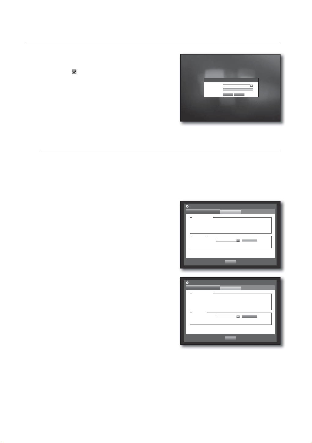
To restrict the user permissions
If the admin restricts all permissions of an added group, the users belonging to that group can access only
the default minimum menus and can change the user’s own password only.
1. Start the DVR.
If all permissions are restricted, only the Login dialog
should appear.
2. Log in with a registered user ID.
Login
ID abc
Password
OK Cancel
3. Right-click any area on the screen.
If all permissions are restricted, only the accessible context
2011-01-01 01:10:25
menus should appear.
Scene Mode
Audio Off
Freeze
Stop Alarm
User Menu
Hide Launcher
Logout
2011-01-01
01:10:25
To change the user password
If you log in with a user account that is restricted to access the menu, you can change your own password
only.
1. Log in with your account.
2. Select <User Menu>.
The Permission Management setup screen appears.
3. Select <Permission Management>.
The Password setup dialog appears.
4. Enter a new password.
5. Select <OK>.
You change to the password will be applied.
Permission Management
User
ID
New Password
Confi rm P/W
abc
************
************
OK Cancel
36_ using the DVR
Page 37

Setting the User
Users can be added only if a group was created in <Group> menu.
Using the mouse may help make setup easier.
1. Use the up/down buttons () in <System> window to
move to <Permission Management>, and press
[ENTER] button.
2. Select <User>.
A window for Add User appears.
3. Use direction buttons (
window.
A window for “Add User” appears.
You can configure the Network Viewer settings including
name, ID, viewer, Select Group and password.
Result of the user setup appears in the <User> window.
To change the user property, use “Edit User”.
The “Edit User” window appears when you select a
desired item to be changed in the <User> window.
• Viewer : If you select <Use>, you will be given access to the
Web Viewer and Network Viewer.
Refer to “Connecting Web Viewer”. (Page 68)
For more information about use of Network Viewer, refer to the
Network Viewer's user guide. (Page 9)
4. When the user setup is done, press <OK>.
◄ ►
) to select <Add> from the
Permission Management
Admin
Group All Group
Group Name ID Viewer Delete
Permission Management
Admin
Group All Group
Group Name ID Viewer Delete
Group
Group
Add User
Name
ID
Viewer Not Used
Select Group ABC
Password
Confi rm P/W
User
OK Cancel
User
OK Cancel
OK Cancel
Setup
Previous/Next Page
Setup
Previous/Next Page
Add
USING THE DVR
Add
Setting Permissions
You can set restricted access for all general users.
Items with restrictions will require logging in for use.
Using the mouse may help make setup easier.
1. Use the up/down buttons () in <System> window to
move to <Permission Management>, and press
[ENTER] button.
2. Select <Setup>.
The Restricted Access, Restriction on Network Access,
Auto Log out, Manual Input of ID setup screen appear.
3. Use direction buttons (
◄ ►
) to move to a desired
item, and set the value.
• Restricted Access : All menu items allowed for a user can
be set with restricted access.
- Checked (
- Not checked (
) : Restricted
) : Accessible
If it is not checked ( ) in <Restricted Access>, any user can access the item no matter what the <Group Authority>
setting.
If it is checked ( ) in <Restricted Access>, a user can access the item only if the user has permission in <Group
Authority> setting.
• Restriction on Network Access : Restricts remote access from a <Restricted Access> network.
- All Network : Restricts all access instances via Network Viewer and Web Viewer.
- Web Viewer : Restricts access via the Web Viewer.
• Auto Log out : A user will be automatically logged out if there is no operation on DVR for over set period of
time.
Permission Management
Admin
Restricted Access
Restriction on Network Access
Auto Log out
Manual Input of ID ON
Group
Live View Backup All
All Network Web Viewer
OFF
OK Cancel
User
Setup
English _37
Page 38
using the DVR
• Manual Input of ID : Prompts you to enter the user ID
manually for the login process.
- Checked (
[] symbols.
Use the virtual keyboard to enter the user ID.
4. When the permission setup is done, press <OK>.
System Management
You can check the system version, update to a newer version, as well as data backup and initialization.
Checking the System Information
You can check the current system version, broadcasting system, MAC address. You can update the system.
Using the mouse may help make setup easier.
1. Use the up/down buttons () in <System> window to
move to <System Management>, and press [ENTER]
button.
2. Check the Version, Broadcast Format, and MAC Address.
• System Information : Shows the current system’s
information.
The values can not be changed by a user.
• S/W Upgrade : Updates the DVR’s software.
) : Encloses the registered user IDs with the
Login
ID
Password
OK Cancel
System Management
System Information
System Information
Software Version
Broadcast Format
MAC Address 00:00:F0:54:FF:FF
S/W Upgrade
Device
Version No S/W Data
v1.0xh_yymmddhhmmss
NTSC
No Device
*****
Settings
Upgrade
Previous
Ex : If you connect to a storage device that has upgradable software
installed, and return to the <System Management> menu, the
current software version will be displayed.
38_ using the DVR
System Management
System Information
System Information
Software Version
Broadcast Format
MAC Address 00:00:F0:54:FF:FF
S/W Upgrade
Device
Version
v1.0xh_yymmddhhmmss
NTSC
USB2FlashStorage
v1.0xh_yymmddhhmmss
Settings
Upgrade
Previous
Page 39

• Updating the Software
1. Connect a device storing the software to be updated.
(It may take about 10 seconds to recognize the device.)
Upgradeable devices include USB memory and network device.
To update the network, the current DVR should have been
connected to the network.
Upgrade via the proxy server may not be enabled due to the
restricted access.
2. Select <System Management> from <System> window.
System Management
System Information
System Information
Software Version
Broadcast Format
MAC Address 00:00:F0:54:FF:FF
S/W Upgrade
Device USB2FlashStorage
Version V1.08_090731170402
v1.0xh_yymmddhhmmss
System Upgrade
NTSC
Current Version v1.0xh_yymmddhhmmss
New Version v1.0xh_yymmddhhmmss
Do you want to upgrade?
OK Cancel
Settings
Upgrade
Previous
3. Select <System Information>.
4. When the recognized device appears, select <Upgrade>.
The <Upgrade> button will be activated only if the current <Software Version> of the <System Information> is
same to or older than that of <S/W Upgrade>.
USING THE DVR
5. Press <OK> in the “System Upgrade” window.
While updating, it shows the progress.
• Updating progresses with 3 steps as shown in the figure.
6. When the updating is done, it automatically restarts.
Do not turn the power off until it finishes restarting.
System Management
System Information
System Information
Software Version
Broadcast Format
MAC Address 00:00:F0:54:FF:FF
S/W Upgrade
Device USB2FlashStorage
Version V1.08_090731170402
S/W Upgrade
Software upgrading...
v1.0xh_yymmddhhmmss
NTSC
System Management
System Information
System Information
Software Version
Broadcast Format
MAC Address 00:00:F0:54:FF:FF
S/W Upgrade
Device USB2FlashStorage
Version V1.08_090731170402
S/W Upgrade
S/W Upgrade
Software upgrading...
Do not turn off during the upgrade.
v1.0xh_yymmddhhmmss
NTSC
Software upgrading...
Settings
Upgrade
Previous
Settings
Upgrade
Previous
If “Upgrade Failed” appears, retry from the step 4.
M
When you experience continued failure, consult the service
center for assistance.
When you perform S/W update remotely using Smart Viewer,
it may take a max of 3 minutes to complete the update since
Smart Viewer popped up a confirmation message. This is to
guarantee that the DVR set operates stably. For a faster
update, use the USB cable to connect to the DVR set.
English _39
Page 40

using the DVR
Settings
You can copy and import the DVR settings by using a storage media.
Using the mouse may help make setup easier.
1. Use the up/down buttons () in <System> window to
move to <System Management>, and press [ENTER]
button.
2. Select <Settings>.
A window of storage device and load factory default
appears.
3. Use direction buttons (
◄ ►
item, and export or import settings data to a storage
device.
• Storage Device : Shows the connected storage device.
• Export : Exports DVR settings to the connected storage device.
• Import : Imports DVR settings from the storage device and applies to the DVR.
If <Include Network Settings> is checked, the network settings will be imported too.
) to move to a desired
System Management
System Information
Storage Device 0 MB (Remained Capacity)
DVRUSB
USBDVR
Include Network Settings
Load Factory Default
10041400
No data
Settings
Default
Previous
Export
Import
• Load Factory Default : If <Default> is selected, a
confirmation dialog for “Load Factory Default” prompts.
Press <OK> to initialize the system to the factory default.
4. To move to the previous menu, press <Previous>.
System Management
System Information
Storage Device 0 MB (Remained Capacity)
Load Factory Default
DVRUSB
USBDVR
Sure to Default Setting?
Include Network Settings
Load Factory Default
10041400
No data
OK Cancel
Default
Settings
Previous
Export
Import
Log Information
You can browse logs on the system and events.
System Log
System Log shows log and timestamp on every system start up, system shutdown, and changes on system
settings.
Using the mouse may help make setup easier.
1. Use the up/down buttons () in <System> window to
move to <Log Information>, and press [ENTER] button.
2. Select <System Log>.
Refer to “Using the Calendar”. (Page 33)
Click on the calendar <
> to display the calendar window.
Log Information
System Log
Search Day 2011-01-01
First Page
No. Log List Date/Time
Event Log
Last Page
Backup Log
Search
Type View all
• Type : When there are too many logs, you can display logs of
the desired format by selecting the type.
3. Use direction buttons (
◄ ►
) to move to a desired item,
and press <Search>.
40_ using the DVR
Previous/Next Page
Previous
Page 41

Event Log
Event log shows recorded events on alarms, motion detections and video loss.
It also shows the log and its timestamp.
Using the mouse may help make setup easier.
1. Use the up/down buttons () in <System> window to
move to <Log Information>, and press [ENTER] button.
2. Select <Event Log>.
3. Use direction buttons (
◄ ►
) to move to the desired
item.
4. Set Search Day, Channel and Type and the press
<Search>.
Refer to “Using the Calendar”. (Page 33)
Click on the calendar <
> to display the calendar window.
Log Information
System Log
Search Day 2011-01-01
No. Log List Date/Time
7 Motion Detection [CH 1] 2011-01-01 00:02:14
6 Motion Detection [CH 2] 2011-01-01 00:02:14
5 Motion Detection [CH 3] 2011-01-01 00:02:14
4 Motion Detection [CH 4] 2011-01-01 00:02:18
3 Motion Detection [CH 3] 2011-01-01 00:02:18
2 Motion Detection [CH 2] 2011-01-01 00:02:18
1 Motion Detection [CH 1] 2011-01-01 00:02:18
First Page
Event Log
Last Page
CH All CHs Type View all
Previous
Backup Log
Search
Previous/Next Page
Backup Log
You can find out who backed up and the details (backup time, channel, device to use, file format, etc.).
Using the mouse may help make setup easier.
1. In the <System> window, press the up/down () button
to move to <Log Information> and press the [ENTER]
button.
2. Select <Backup Log>.
3. Use the four direction buttons (
◄ ►
) to move to a
desired item.
4. Specify a search term and select <Search> in the right
corner.
Backup details for the search term will be listed.
Log Information
System Log
Search Day 2011-01-01 ~ 2011-01-02
First Page
No. User Date/Time
Event Log
Last Page
Backup Log
Previous/Next Page
Previous
Search
USING THE DVR
English _41
Page 42
using the DVR
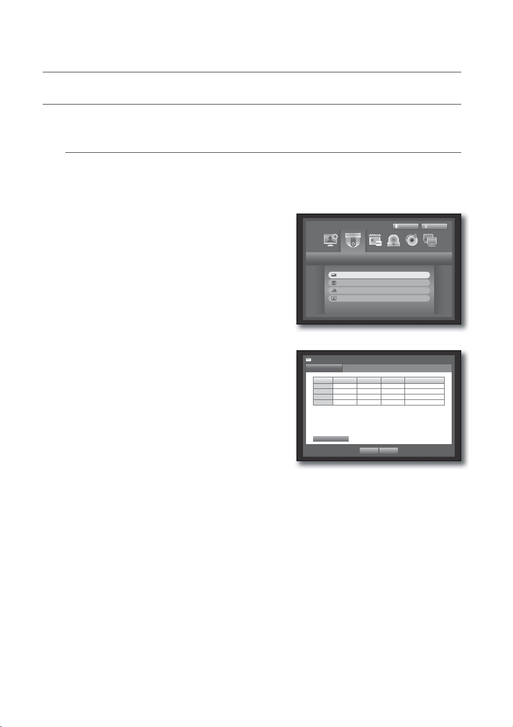
SETTING THE DEVICE
You can setup Camera, Storage Device, Remote Device and Monitor.
Camera
Setting the Camera
You can set Video, Audio, Channel Name and Dwell Time of a Camera.
Using the mouse may help make setup easier.
1. Press the [MENU] button on the remote control.
2. Use the left/right button (
Device setting menu is selected.
3. Use the up/down buttons (
and press [ENTER] button.
◄ ►
) to select <Device>.
) to move to <Camera>,
Device
Camera
Storage Device
Remote Device
Monitor
Logout
Return
4. Select <Camera>.
You will see a window where you can configure the
camera settings including Video, Audio, CH Name, SEQDwell Time.
5. Use direction buttons (
◄ ►
) to move to a desired
Camera
Camera
CH Video Audio CH Name SEQ-Dwell Time
1 ON OFF CAM 01 5 sec
2 ON OFF CAM 02 5 sec
3 ON OFF CAM 03 5 sec
4 ON OFF CAM 04 5 sec
item, and set the value.
• Video
- <ON/OFF> : You can turn ON/OFF the selected
Screen Setup
OK Cancel
channel’s camera.
- <Covert1> : Shows information other than the video of the selected channel.
For privacy protection, it does not display the video while the recording continues.
- <Covert2> : Shows nothing but an empty screen while the recording continues.
• Audio
- If set to <ON>, you can turn the audio of the channel ON/OFF on the Live screen.
- If set to <OFF>, the channel’s audio is off on the Live screen and not recorded.
- For SEB-1006R (MIC integrated camera), you must connect it to CH1 and set CH1 Audio to “ON” in the
Camera menu.
Audio output is available for only CH1.
42_ using the DVR
Page 43
• CH Name : Up to 15 characters including blanks are allowed. (The first character should not be empty.)
Refer to “Using Virtual Keyboard”. (Page 34)
• SEQ-Dwell Time : You can set the dwell time between channels for the Live screen and Spot Out.
If set to <OFF>, the channel is not listed in the Auto Sequence mode.
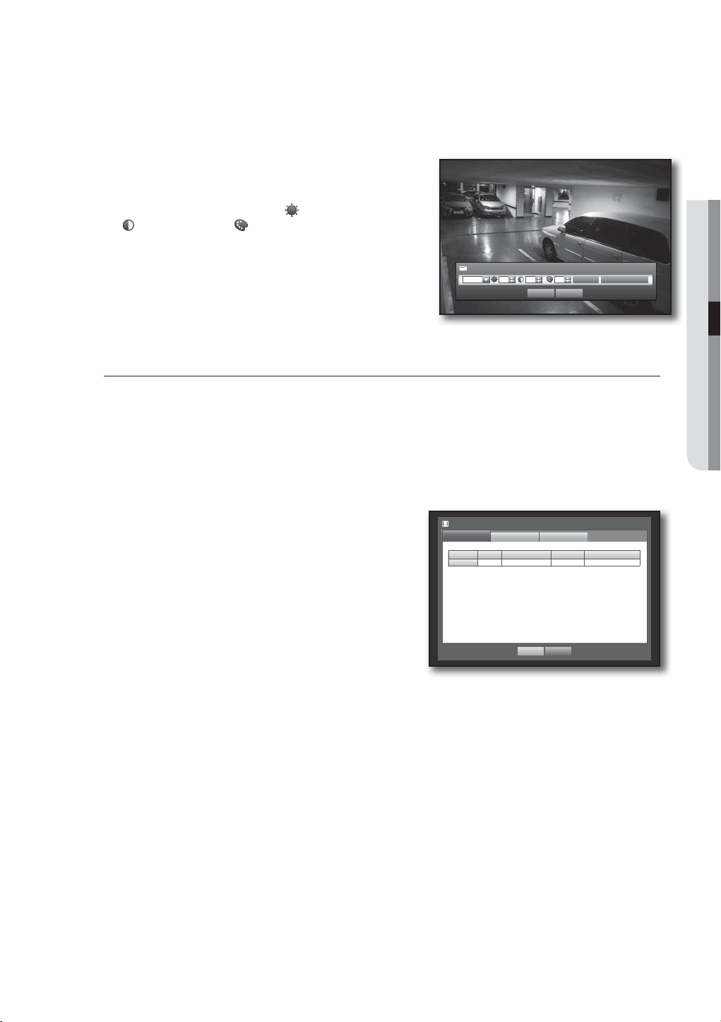
• Screen Setup : The video appeared on the screen may vary
depending on the channel’s camera, configure the DVR display
to your preferences.
Select a channel and adjust the
<
(Contrast)>, and <(Color)> of the selected channel.
<
(Brightness)>,
• Press the <Init> to initialize settings back to the default 50.
6. When the camera setup is done, press <OK>.
Screen Setup
CH1 50 50 50
OK Cancel
Init Apply to All CH
Storage Device
You can check information on storage devices.
Confirming Devices
You can check storage devices and their free space, usage as well as status.
Devices available are HDD, and USB devices (Memory, HDD).
Using the mouse may help make setup easier.
1. Use the up/down buttons () in <Device> window to
move to <Storage Device>, and press [ENTER] button.
2. Select <Device>.
• No. : Shows the assigned number of the internal HDD.
• Used/Total : Shows the used/total capacity of the storage
device.
• Used : Sets the storage device’s usage.
- USB memory
is used for backup purpose only.
• Status/Management : Shows the current status of the HDD,
as in Normal/Check/Replace.
- Normal : Available to use
- Check : Available to use but recommended to replace
- Replace : Requires immediate replacement.
3. To move to the previous menu, press <OK>.
Storage Device
Device
Device No. Used/Total Used Status/Management
HDD 1 12.28G/499.37G Internal Normal
HDD Map
Format
OK Cancel
HDD Alarm
USING THE DVR
English _43
Page 44

using the DVR
Formatting
You can format a storage device.
Using the mouse may help make setup easier.
1. Use the up/down buttons () in <Device> window to
move to <Storage Device>, and press [ENTER] button.
2. Select <Format>.
A window for selection of device for formatting appears.
3. Use direction buttons (
formatted.
◄ ►
) to select a device to be
Storage Device
Device
Device Select Used/Total Used
HDD 1 12.28G/499.37G Internal
Format
Format
OK Cancel
HDD Alarm
4. Select <Format> on the bottom of the screen.
Press <OK> on the “Manage” confirmation window will
start formatting the selected device.
5. When the formatting is done, press <OK>.
Even when formatted, used HDD space will not be 0 GB due
M
to the space reserved by the system required for operating.
Storage Device
Device
Device Select Used/Total Used
HDD 1 12.28G/499.37G Internal
Format
Manage
Format
HDD Alarm
Formatting deletes all recordings.
Proceed formatting?
OK Cancel
OK Cancel
44_ using the DVR
Page 45

HDD Alarm
You can set alarm settings for HDD defects such as Check Alarm Output Port, Replace Alarm Output Port,
and its duration.
Using the mouse may help make setup easier.
1. Use the up/down buttons () in <Device> window to
move to <Storage Device>, and press [ENTER] button.
2. Select <HDD Alarm>.
A window for setting HDD check and replace output ports
and their durations appears.
3. Use direction buttons (
◄ ►
) to move to the desired
item.
Storage Device
Device
Check Alarm Output Port
Duration OFF
Replace Alarm Output Port
Duration OFF
Format
HDD Alarm
1 BEEP
All
1 BEEP
All
USING THE DVR
• Alarm
OK Cancel
- Alarm signal will output through the alarm out port on the
rear side when selected <1>.
- If <BEEP> was selected, a beep will sound.
- If <All> was selected, both beep sound and alarm signal through rear side ports will output.
• Check Alarm Output Port : If HDD generates check alarm, the alarm signal will output to the specified alarm
output port.
• Replace Alarm Output Port : If HDD generates replace alarm, the alarm signal will output to the specified
alarm output port.
• Duration : Sets the alarm duration for the alarm signal and beep sound.
<Check> status means that the HDD is operating but it has problems that require technical examination.
M
) appears on the Live screen.
(
<Replace> status means that the HDD has defect and requires immediate replacement.
) appears on the Live screen.
(
4. When the HDD Alarm setup is done, press <OK>.
Remote Devices
Specify the use of remote control and the remote control ID so that you can synchronize with the DVR.
Using the mouse may help make setup easier.
1. Use the up/down buttons () in <Device> window to
move to <Remote Device>, and press [ENTER] button.
2. Make sure to match IDs of the DVR, Remote Control and
press <OK>.
Remote Device
Remote Control ON ID 00
For changing the remote control’s ID, refer to “Changing the
M
Remote Control ID”. (Page 12)
OK Cancel
English _45
Page 46

using the DVR
Monitor
You can select which item(s) to be displayed on the screen.
Setting the Monitor
Using the mouse may help make setup easier.
1. Use the up/down buttons () in <Device> window to
move to <Monitor>, and press [ENTER] button.
2. Select <Monitor>.
3. Use direction buttons (
◄ ►
) to move to a desired
item, and set the value.
• Event Display : Sets the dwell time of the event channel
display on the monitor when an event occurs.
If selected <Continuous>, it displays the channel until you
press [ALARM] button to release it.
• Display : Displays only checked items on the monitor
screen.
4. When the monitor setup is done, press <OK>.
Setting Display position
Some monitors many not display information (camera name, icon, time information, etc.) about the DVR,
depending on the condition. Then, you can change the display position of the data.
1. In the <Device> window, press the up/down (
button.
2. Select the <Monitor> item.
3. Select <Display Position Setup> in the bottom.
You will move to the <Display Position Setup> window.
4. Use the four direction buttons or the number buttons on
the remote control to adjust the data position.
) button to move to <Monitor> and press the [ENTER]
Monitor
Monitor
Event Display OFF
Display Date Time CH Name Icon
Display Position Setup
Spot Out
OK Cancel
2011-01-01 01:10:25
Display Position Setup
30 30
OK Cancel
Mode
30
30
46_ using the DVR
Page 47

Setting the Spot Out
You can set the DVR to output information / video apart from the monitor out.
Using the mouse may help make setup easier.
1. Use the up/down buttons () in <Device> window to
move to <Monitor>, and press [ENTER] button.
2. Select <Spot Out>.
The number of Spot Out terminals differs according to the
model.
Monitor
Monitor
Spot Out 1 SEQ
Event Display OFF
Spot Out
Mode
Set Mode
All
USING THE DVR
3. Use direction buttons (
◄ ►
) to move to a desired
item, and set the value.
• Spot Out 1 : You can select between Auto Sequence, and
Single.
• Set Mode : A window for “Set Spot Out” appears and you
can set the channel for it.
You can set the dwell time between the screen switching in
“Setting the Device > Camera > SEQ-Dwell Time”.
(Page
43)
You can setup using the mouse right button in Live screen.
M
Refer to “Spot Out”. (Page 29)
4. When the Spot Out is done, press <OK>.
Setting the Screen Mode
You can configure the Live screen and Split Screens.
Using the mouse may help make setup easier.
1. Use the up/down buttons () in <Device> window to
move to <Monitor>, and press [ENTER] button.
2. Select <Mode>.
3. Use direction buttons (
◄ ►
item, and set the value.
• Live Screen : Select split modes for the Live screen.
4-split screens are included by default.
• Play Screen : Select split modes for the playback screen.
Single screen and 4-split screen are provided by default.
4. When the screen mode setup is done, press <OK>.
) to move to a desired
OK Cancel
Monitor
Monitor
Spot Out 1 SEQ
Event Display OFF
Monitor
Monitor Spot Out
Spot Out
Set Spot Out
1 2 3 4
OK
OK Cancel
Live Screen
Play Screen
OK Cancel
Mode
Set Mode
Mode
All
Live Play
English _47
Page 48

using the DVR
SETTING THE RECORDING
You can setup scheduled recording, event recording and other recording related settings.
Recording Schedule
Make your reservation on a date and time to schedule the recording on specified time.
Using the mouse may help make setup easier.
1. Press the [MENU] button on the remote control.
2. Use the left/right button (
Record menu is selected.
3. Use the up/down buttons (
Schedule>, and press [ENTER] button.
◄ ►
) to select <Record>.
) to move to <Recording
Recording Schedule
Event Record Duration
REC Quality & Resolution
Record Option
Record
Logout
Return
4. Select <Recording Schedule>.
A window of scheduled recording setup appears.
5. Use direction buttons (
◄ ►
) to move to a desired
item, and set the value.
• Apply to All CH : If selected <Apply to All CH>, “Apply to
All CH” window appears.
Press <OK> to apply the setup to all channels.
6. When the recording schedule setup is done, press <OK>.
Recording Schedule
CH1
0 1 2 3 4 5 6 7 8 9 10 11 12 13 14 15 16 17 18 19 20 21 22 23
All
Sun
Mon
Tue
Wed
Thu
Fri
Sat
Hol
No Recording Continuous Event
Both(Cont&Evnt)
OK Cancel
Recording Schedule
CH1
0 1 2 3 4 5 6 7 8 9 10 11 12 13 14 15 16 17 18 19 20 21 22 23
All
Sun
Apply to All CH
Mon
Tue
Wed
Apply recording schedule to all channels?
Thu
Fri
Sat
Hol
No Recording Continuous Event
Both(Cont&Evnt)
OK Cancel
OK Cancel
Apply to All CH
Apply to All CH
48_ using the DVR
Page 49

Recording Color Tags
Color Function Description
White No Recording No schedule / event recording
Orange Continuous Scheduled recording only
Blue Event Event recording only
Green Both(Cont&Evnt) Both scheduled / event recordings
Each press of a selected cell will cycle through <No Recording>-<Continuous>-<Event><Both(Cont&Evnt)>.
Event Record Duration
You can set the beginning and ending point of a recording on an event.
Using the mouse may help make setup easier.
1. Use the up/down buttons () in <Record> window to
move to <Event Record Duration>, and press [ENTER]
button.
2. Use direction buttons (
◄ ►
) to move to a desired
item, and set the value.
• Pre Event : The recording of an event will start at a
pre-determined time prior to the actual occurrence of the event.
If it is set to 5 seconds, the recording begins from 5
seconds before the event.
• POST Event : The recording will continue for a
pre-determined time after the actual end of an event.
If it is set to 5 seconds, the recording ends in 5 seconds after an event.
Event Record Duration
CH Pre Event POST Event
1 OFF
2 OFF
3 OFF
4 OFF
OK Cancel
1 min
1 min
1 min
1 min
USING THE DVR
3. When the event recording duration setup is done, press <OK>.
REC Quality / Resolution
You can set resolution, fps and quality of recordings by channel, and by recording type of standard / event.
Setting Standard Recording Properties
You can set each channel’s resolution, quality and fps for normal recordings.
Using the mouse may help make setup easier.
1. Use the up/down buttons () in <Record> window to
move to <REC Quality & Resolution>, and press
[ENTER] button.
2. Select <Standard>.
3. When the recording setup is done, press <OK>.
REC Quality & Resolution
Standard
Remaining count : 4CIF(L) : 2 2CIF(M) : 4 CIF(S) : 8
CH Resolution Record Rate Record Quality
1 CIF(S) 7fps Level4
2 CIF(S) 7fps Level4
3 CIF(S) 7fps Level4
4 CIF(S) 7fps Level4
Event
OK Cancel
English _49
Page 50

using the DVR
Setting Event Recording Properties
You can set each channel’s resolution, quality and fps for event recordings.
Using the mouse may help make setup easier.
1. Use the up/down buttons () in <Record> window to
move to <REC Quality & Resolution>, and press
[ENTER] button.
2. Select <Event>.
Event recording setup window appears.
3. Use direction buttons (
item, and select it.
• Resolution : Sets the resolution of the recorded screen.
• Record Rate : Image Per Second, means the frames
recorded per a second.
• Record Quality : Sets the recording quality.
The estimated total remaining count means the total number of remaining recordings for both standard and event
M
recordings.
You cannot increase the remaining count if the current remaining count has reached zero or there is no available
remaining count from any other page. If this is the case, reduce the remaining count for the current page, or do so
for the same channel on any other page.
4. When the Event recording setup is done, press <OK>.
◄ ►
) to move to a desired
REC Quality & Resolution
Standard
Remaining count : 4CIF(L) : 2 2CIF(M) : 4 CIF(S) : 8
CH Resolution Record Rate Record Quality
1 4CIF(L) 7fps Level4
2 4CIF(L) 7fps Level4
3 4CIF(L) 7fps Level4
4 4CIF(L) 7fps Level4
Event
OK Cancel
Record Option
You can set the recording to stop or overwrite when the HDD is full.
Using the mouse may help make setup easier.
1. Use the up/down buttons () in <Record> window to
move to <Record Option>, and press [ENTER] button.
2. Use direction buttons (
◄ ►
) to move to a desired
item, and set the value.
• Disk End Mode : If selected <Overwrite>, recording will
continue despite the HDD full while overwriting the oldest.
If selected <Stop>, the recording will stop when the HDD is
full.
• Disk End Beep : If selected <Stop>, the button is activated.
If you check it, the beep will sound on the disk full and the
recording stops.
• Auto Delete : If you check it, Record Period setup is activated.
If you specify the auto deletion period, the recording data before the period will be deleted automatically.
This option will be enabled only if Disk End Mode is set to “Overwrite”.
3. When the recording option setup is done, press <OK>.
Record Option
Disk End Mode Overwrite
Disk End Beep
Auto Delete
Auto Delete
180 day
The recording information will be deleted.
Do you want to proceed?
OK Cancel
OK Cancel
50_ using the DVR
Page 51

SETTING THE EVENT
You can set recording options for sensor, motion, and video loss event.
Sensor Detection
You can set the sensor’s operating condition and connected camera, as well as alarm output and its duration.
Using the mouse may help make setup easier.
1. Press the [MENU] button on the remote control.
2. Use the left/right button (
◄ ►
) to select <Event>.
Event setting menu is selected.
Sensor Detection
Motion Detection
Video Loss Detection
Alarm Schedule
Logout
Event
USING THE DVR
Return
3. Use the up/down buttons (
) to move to <Sensor
Detection>, and press [ENTER] button.
A window of sensor detection setup appears.
4. Use direction buttons (
◄ ►
) to move to a desired
item, and set the value.
• Sensor Operation : Sets the operation mode of sensors.
- <OFF> : Sensor does not operate.
- <N.O (Normal Open)> : Sensor is opened.
If the sensor is closed, it generates alarm.
- <N.C (Normal Close)> : Sensor is closed.
If the sensor is open by interruption, it generates alarm.
• Cam : Select a channel to be connected to the sensor.
If selected camera, “
Camera Setup” window appears.
Select a channel and setup the preset.
• Alarm : Sets the alarm output method.
For further information on alarm output, refer to “HDD Alarm >
Alarm”. (Page 45)
• Duration : Sets the duration of alarm signal and alarm
sound.
5. When the sensor detection setup is done, press <OK>.
Sensor Detection
Sensor
Sensor Operation Cam Alarm Duration
1 OFF 1 None 10 sec
2 OFF 2 None 10 sec
3 OFF 3 None 10 sec
4 OFF 4 None 10 sec
OK Cancel
Sensor Detection
Sensor
Sensor Operation Cam Alarm Duration
1 OFF 1 None 10 sec
2 OFF 2 None 10 sec
Camera Setup
3 OFF 3 None 10 sec
4 OFF 4 None 10 sec
CH
1
2
OK Cancel
OK Cancel
CH
3
4
Sensor Detection
Sensor
Sensor Operation Cam Alarm Duration
1 OFF 1 None 10 sec
2 OFF 2 None 10 sec
Alarm Setup
3 OFF 3 None 10 sec
4 OFF 4 None 10 sec
1 BEEP All
OK Cancel
OK Cancel
English _51
Page 52

using the DVR
Motion Detection
You can set target detection region and motion, as well as the alarm signal output.
When the motion detection region is set, it detects motion within the area.
Using the mouse may help make setup easier.
1. Use the up/down buttons () in <Event> window to
move to <Motion Detection>, and press [ENTER] button.
A window of motion detection area setup appears.
2. Use direction buttons (
◄ ►
) to move to a desired
item, and set the value.
• Mode : Sets whether to activate motion detection.
• Sensitivity : Sets the sensitivity level of the motion detection.
• Alarm : Sets the alarm output method.
For further information on alarm output, refer to “HDD Alarm >
Alarm”. (Page 45)
• Alarm Duration : Sets the duration of alarm signal and alarm sound.
3. When the motion detection setup is done, press <OK>.
Setting the Motion Detection Area
Select <Motion Region>.
When “Motion Region” window appears, select a
channel for detection and set the area of motion
detection.
• To set the area in “Motion Region” window
In the “Motion Region” window, select desired region
from <
• To set the area using <Individual> selection
In the “Motion Region” window, you can select cells
individually by using <Individual>.
When selected <Individual>, “Motion Region” window disappears and you can select cells one by one.
When the motion area setup is done, Right-click to select <Menu> in the context menu or the [MENU]
button on the remote control to display the “Motion Region” window again.
- Select : Selected cell is set to be a part of motion detection area.
- Unselect : Selected cell is removed from the motion detection area.
- Inverse : Unselected cells are set to be the motion detection area.
- Menu : After selecting individual motion areas, move to the “Motion Region” window.
If selected <Apply to All CH>, selected motion area is applied to all channels.
When the motion detection setup is done, press <OK>.
>.
Motion Detection
CH Mode Sensitivity Alarm Alarm Duration
1 OFF Level10(High) None 10 sec
2 OFF Level10(High) None 10 sec
3 OFF Level10(High) None 10 sec
4 OFF Level10(High) None 10 sec
Motion Region
CH1
OK Cancel
Individual
OK Cancel
Apply to All CH
Motion Region
Select
Unselect
Inverse
Menu
52_ using the DVR
Page 53

Video Loss Detection
You can set the alarm to be generated on a camera disconnection, which causes a video loss.
Using the mouse may help make setup easier.
1. Use the up/down buttons () in <Event> window to
move to <Video Loss Detection>, and press [ENTER]
button.
A window of video loss detection area setup appears.
2. Use direction buttons (
◄ ►
) to move to a desired
item, and set the value.
Video Loss Detection
CH Video Loss State Alarm Alarm Duration
1 OFF None 10 sec
2 OFF None 10 sec
Help
3 OFF None 10 sec
4 OFF None 10 sec
If a video loss event occurs during the event
recording, the POST recording settings of
the applicable channel will be reset.
OK
• Video Loss State : Sets whether to activate video loss
detection.
• Alarm : Sets the alarm output method.
OK Cancel
For further information on alarm output, refer to “HDD Alarm >
Alarm”. (Page 45)
• Alarm Duration : Sets the duration of alarm signal and alarm sound.
• Help : Displays a help message that will appear if a video loss event occurs.
3. When the video loss detection setup is done, press <OK>.
Alarm Schedule
You can set the conditions and operating hours for scheduled alarms.
Using the mouse may help make setup easier.
1. Use the up/down buttons () in <Event> window to
move to <Alarm Schedule>, and press [ENTER] button.
2. A window of <Alarm Schedule> settings appears.
3. Alarm : Sets the alarm output method.
For further information on alarm output, refer to “HDD Alarm >
Alarm”. (Page 45)
• <ON> : Marked in orange, and always generates alarm on
scheduled time.
• <OFF> : Marked in white, no alarm is generated even if an
event occurs.
• Event Sync : Marked in Blue, generates alarm only when an
event occurs.
• Apply to All Alarm : Applies the configured schedule to all
alarms.
When the alarm is generated on the scheduled time, you can
M
stop the alarm by canceling the schedule.
4. When the Alarm Schedule setup is done, press <OK>.
Alarm Schedule
Alarm1
0 1 2 3 4 5 6 7 8 9 10 11 12 13 14 15 16 17 18 19 20 21 22 23
All
Sun
Mon
Tue
Wed
Thu
Fri
Sat
Hol
OFF ON Event Sync
OK Cancel
Alarm Schedule
Alarm1
0 1 2 3 4 5 6 7 8 9 10 11 12 13 14 15 16 17 18 19 20 21 22 23
All
Sun
Apply to All Alarm
Mon
Tue
Wed
Apply the alarm scheduling to all?
Thu
Fri
Sat
Hol
OFF ON Event Sync
OK Cancel
Apply to All Alarm
Apply to All Alarm
Help
USING THE DVR
OK Cancel
English _53
Page 54

using the DVR
BACKUP
You can check the backup device and set the backup schedule by channel or by time.
The product only supports external HDD of USB memory and USB type. (Page
Setting the Backup
You can backup the desired data to a connected device.
Using the mouse may help make setup easier.
93)
1. Press the [MENU] button on the remote control.
◄ ►
2. Use the left/right button (
) to select <Backup>.
Logout
Return
Backup menu is selected.
Backup
Backup
3. Press the [ENTER] button.
A backup window appears.
You can directly access it from the “Live screen menu”.
(Page 24)
4. Use direction buttons (
◄ ►
) to move to a desired
item, and set the value.
• Backup Range : Sets the <Start> and <End> time for the
backup.
• Channel : Sets the channel to backup.
Backup
Start End
2011-01-01 00:01:06 2011-01-01 08:25:45
Overlap List0
1 2 3 4 ALL
Device USB-Storage
Folder \20110101\
Check capacity
OK Cancel
Type DVR
Filename 0001
Backup
Used
Free
Change
You can select multiple channels.
• Device : Select a backup device from the recognized devices.
• Type : Sets the backup data format.
- DVR : Saved data can be played back only by the DVR.
- SEC : Saves data in the Samsung’s proprietary format with built-in viewer, which supports immediate
playback on a PC.
• Filename : You can set the back file name.
Refer to “Using Virtual Keyboard”. (Page 34)
• Check capacity : Shows the size of the selected backup data, used and available capacity of the selected
backup device.
Checking will stop if the backup size is over 200%.
• Overlap : Shows a list of overlapping data on a same time according to the number of data.
It appears when one channel has multiple data on a certain time point due to changing of time or time zone
settings, etc.
Refer to time and time zone of “Setting the Date/Time/Language”. (Page 32)
54_ using the DVR
Page 55

5. When the backup setup is done, press <OK>.
If no available device is recognized for backup, <OK> button is not activated.
The application may slow down during the backup.
J
You can switch to the menu screen during the backup in operation, but playback of data is not available.
If backup has failed, select “Device > Storage Device” and check the free space of the HDD and check also if the
HDD is properly connected.
Pressing the <Return> during the backup will return to the previous menu, while the backup progresses.
M
NETWORK CONFIGURATION
It provides networked monitoring of Live screen from a remote place, and supports mail forwarding function with
events. You can configure the network environment which enables such functions.
Connection Mode
You can set the network connection route and protocol.
Setting the Connection
Sets the protocol and environment of the network.
Using the mouse may help make setup easier.
1. Press the [MENU] button on the remote control.
◄ ►
2. Use the left/right button (
) to select <Network>.
Network menu is selected.
3. Use the up/down buttons (
) to move to <Connection
Mode>, and press [ENTER] button.
Connection Mode
DDNS
Live Transfer
Mailing Service
Logout
Return
Network
USING THE DVR
4. Select <Connection>.
A window of connection mode setup appears.
5. Use direction buttons (
◄ ►
) to move to a desired
item, and set the value.
• Connection Mode : Sets the network connection mode.
• Bandwidth : Sets the maximum data flow to be transferred.
(Upload speed)
Options will vary depending on the selected connection
mode.
- For <Static IP>, <Dynamic IP> : Select one from 50
kbps ~ 2Mbps, and Unlimited.
- For <ADSL>, select one from 50 kbps ~ 600 kbps.
Connection Mode
Connection
Connection Mode Static IP
Bandwidth 2Mbps
IP 192.168. 1.200
Gateway 192.168. 1. 1
Subnet Mask 255.255.255. 0
DNS
Protocol
Manual 168.126. 63. 1
OK Cancel
English _55
Page 56

using the DVR
• IP, Gateway, Subnet Mask, and DNS
- For <Static IP> : You can directly input IP address,
Gateway, Subnet Mask and DNS.
- For <Dynamic IP> : IP address, Gateway, and Subnet
Mask are set automatically.
- For <ADSL> : IP address, Gateway, and Subnet Mask
are set automatically.
• User ID, Password : In case you selected ADSL, provide the
“User ID” and its “Password”.
DNS server for <Dynamic IP> and <ADSL> can be set by user only if you selected <Manual>.
M
Connection Mode
Connection
Connection Mode ADSL
Bandwidth 600kbps
IP
Gateway
Subnet Mask
DNS Manual 168.126. 63. 1
User ID ID
Password
Protocol
192.168. 1.200
192.168. 1. 1
255.255.255. 0
************
OK Cancel
6. When the connection setup is done, press <OK>.
Setting the Protocol
1. Use the up/down buttons () in <Network> window to
move to <Connection Mode>, and press [ENTER]
button.
2. Select <Protocol>.
3. Use direction buttons (
◄ ►
) to move to a desired
item, and set the value.
• Protocol Type : Select the protocol type between TCP and
UDP.
If selected UDP, selections of Port (TCP), Port (UDP), and Unicast/
Multicast are activated.
If setting the connection mode to ADSL, you cannot select UDP for the protocol type.
• Port(TCP) : Initially, <554~558> is set. It increases / decreases by 5.
- TCP: It has better stability and lower speed when compared to UDP, and recommended for internet
environments.
• Port(UDP) : Initially, <8000~8160> is set. It increases / decreases by 160.
- UDP : It has less stability and faster speed when compared to TCP, and recommended for local area
network (LAN) environments.
• Unicast/Multicast : Select one between Unicast and Multicast.
If selected Multicast, Multicast IP and TTL are activated.
- Unicast : Transfers data (UDP, TCP) individually to each connecting client.
- Multicast : Multiple client can receive the data (only in UDP) without putting additional traffic load to the
network.
• Multicast IP : User can directly input.
• TTL : Select from 0 ~ 255. Initial value for the TTL is set to <5>.
• Webviewer Port : Enter the port number for the Web Viewer. Initially, it is set to <80>.
Connection Mode
Connection
Protocol Type TCP
Port(TCP) 554 ~
Port(UDP)
Unicast/Multicast
Multicast IP
TTL
Webviewer Port 80
Protocol
8000 ~ 8160
Unicast
224.126. 63. 1
5
OK Cancel
558
As UDP protocol may cause a packet loss on the network, it is recommended to use TCP protocols.
M
If you select UDP protocols and set port forwarding in the IP router, ending up with an unstable network connection,
configure the DMZ settings in the IP router as necessary.
4. When the protocol setup is done, press <OK>.
56_ using the DVR
Page 57
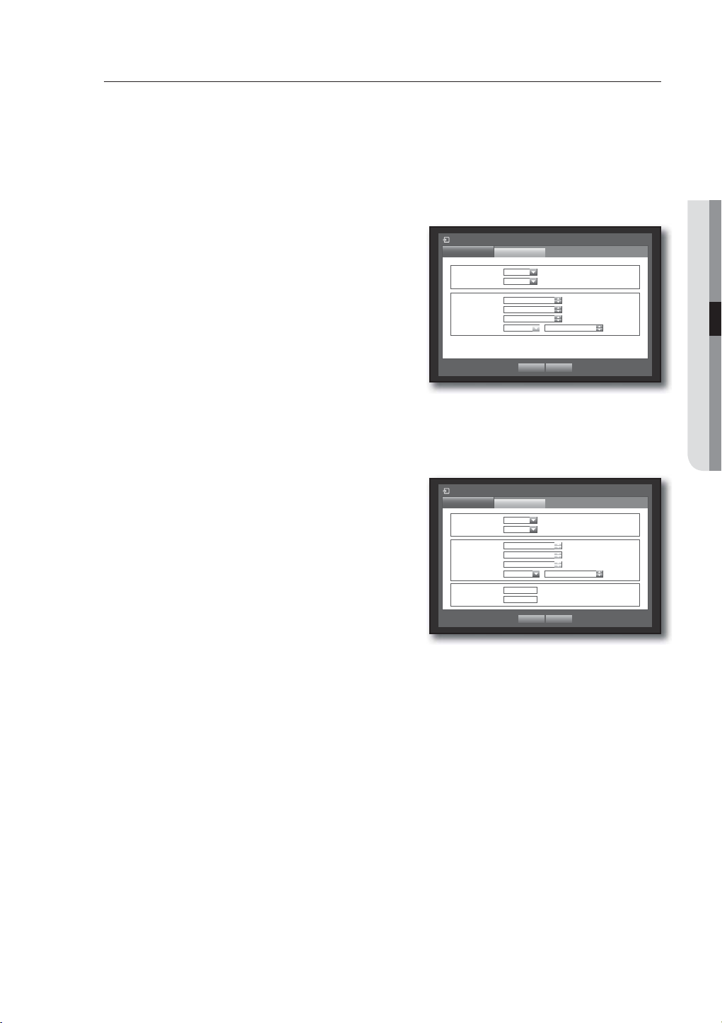
Connecting and Setting the Network
Networking may differ from the connection method, check your environment before setting the connection
mode.
When no router is used
• Static IP mode
- Internet connection : Static IP ADSL, leased line, and LAN environments allows connection between the
DVR and remote user.
- DVR Network Settings : Set the <Connection Mode> in
<Connection> menu of the connected DVR to <Static IP>.
Consult your network manager for IP, Gateway and Subnet Mask.
• Dynamic IP (DHCP) mode
- Internet connection : Connect the DVR directly to a cable
modem, DHCP ADSL modem or FTTH network.
- DVR Network Settings : Set the <Connection Mode> in
<Connection> menu of the connected DVR to <Dynamic
IP>.
• ADSL (PPPoE: ID and password certification)
- Internet connection : An ADSL modem is directly connected to the DVR, where the ADSL connection
requires user ID and password.
- DVR Network Settings : Set the <Connection Mode> in
<Connection> menu of the connected DVR to <ADSL>.
ADSL <User ID> and <Password> should be the same to the
ADSL user information.
If you don’t know the ID and password, consult your ADSL service
provider.
Connection Mode
Connection
Connection Mode Static IP
Bandwidth 2Mbps
IP 192.168. 1.200
Gateway 192.168. 1. 1
Subnet Mask 255.255.255. 0
DNS
Protocol
Manual 168.126. 63. 1
OK Cancel
Connection Mode
Connection
Connection Mode ADSL
Bandwidth 600kbps
IP
Gateway
Subnet Mask
DNS Manual 168.126. 63. 1
User ID ID
Password
Protocol
192.168. 1.200
192.168. 1. 1
255.255.255. 0
************
OK Cancel
USING THE DVR
English _57
Page 58
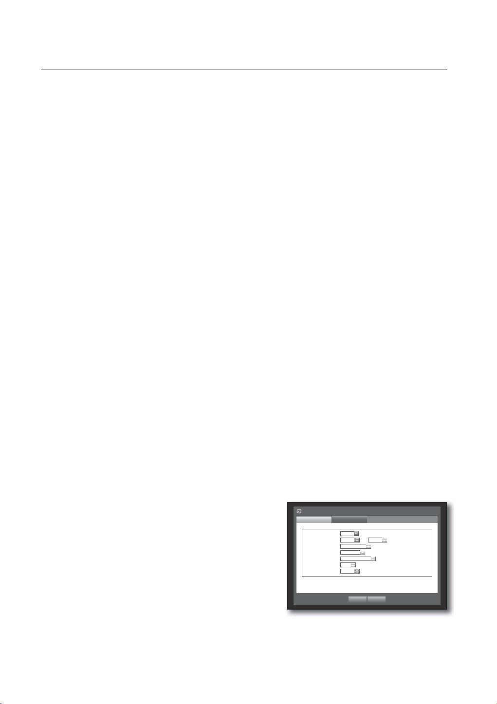
using the DVR
When a router is used
To avoid IP address conflict with the DVR's static IP, check followings :
J
• Setting the DVR with a static IP
- Internet connection : You can connect the DVR to a router which is connected to an ADSL/Cable modem or
a router in a Local Area Network (LAN) environment.
• Setting the DVR Network
1. Set the <Connection Mode> in <Connection> menu of the connected DVR to <Static IP>.
2. Check whether the set IP address is in the static IP range provided by the Broadband Router.
IP, Gateway, and Subnet Mask : Consult your network manager.
Check whether the set IP address is in the static IP range provided by the Broadband Router.
If a DHCP server is configured with starting address (192.168.0.100) and end address (192.168.0.200), you should
J
set the IP address out of the configured DHCP range (192.168.0.2 ~ 192.168.0.99 and 192.168.0.201 ~
192.168.0.254).
3. Check the Gateway address and subnet mask are equal to those set in the Broadband Router.
• Setting the DHCP IP Address of the Broadband Router
1. To access the Broadband Router’s configurations, open a web browser on the local PC that is connected
to the Broadband Router and enter the router’s address (ex : http://192.168.1.1).
2. At this stage, make the local PC's windows network configurations to the below example :
Ex) IP : 192.168.1.2
Subnet Mask : 255.255.255.0
Gateway : 192.168.1.1
- Once connected to the Broadband Router, it prompts with password. While entering nothing to the User
Name field, enter “admin” into the password field and press <OK> to access the router configurations.
- Access the router’s DHCP configuration menu and set its DHCP server activation, and provide the start and
end address.
Set the start address (192.168.0.100) and end address (192.168.0.200).
Above steps may differ from the router devices depending on the manufacturer.
M
• Setting Router’s Port Forwarding
1. Set the protocol to <TCP>.
2. External Port Range : Enter the TCP Port set in the
<Port(TCP)> in <Protocol> menu of the connected DVR.
If more than one DVRs are connected to the router, the
TCP port can be different.
3. Internal PC IP Address : Enter the IP address set to the
<IP> in <Connection> menu of the connected DVR.
4. Internal Port Range : Set the same to the “External Port
Range”.
Above steps may differ from the router devices depending on the manufacturer.
M
Port forwarding is required when you want to access the DVR connected to the router from outside of the router’s
network.
58_ using the DVR
Connection Mode
Connection
Protocol Type TCP
Port(TCP) 554 ~
Port(UDP)
Unicast/Multicast
Multicast IP
TTL
Webviewer Port 80
Protocol
8000 ~ 8160
Unicast
224.126. 63. 1
5
OK Cancel
558
Page 59
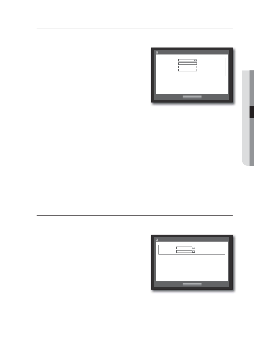
DDNS
You can set the DDNS site for a remote user’s network connection.
Using the mouse may help make setup easier.
1. Use the up/down buttons () in <Network> window to
move to <DDNS>, and press [ENTER] button.
2. Use virtual keyboard to enter user inputs.
Refer to “Using Virtual Keyboard”. (Page 34)
DDNS
DDNS Site
Host Name
User Name
User Password
DDNS Host Address http://www.samsungipolis.com/
iPOLiS
www.samsungip...
If selected <OFF> or <iPOLiS>, input fields are deactivated.
If you select <iPOLiS>, the “DDNS host address” item will be
displayed.
3. When the DDNS setup is done, press <OK>.
OK Cancel
DDNS Setting
DDNS is a short form of Dynamic Domain Naming System.
DNS (Domain Name System) is a service that routes a domain name consisting of user friendly characters
(ex : www.google.com) to an IP address consisting of numbers (64.233.189.104).
DDNS (Dynamic DNS) is a service that registers a domain name and the floating IP address with the DDNS
server so that the domain name can be routed to the IP address even if the IP is changed in a dynamic IP
system.
• Setting DDNS in the DVR
Set <Protocol Type> in the <Protocol> menu of the connected DVR to the following :
Ex) Protocol Type : TCP
Port (TCP) : 0554, 0555, 0556, 0557, 0558
DDNS Site :
iPOLiS
USING THE DVR
Live Transfer
Sets the quality of the image that is transferred from the DVR to the network.
Using the mouse may help make setup easier.
1. In the <Network> setting window, press the up/down
() button to move to <Live Transfer> and press the
[ENTER] button.
The Live Transfer window appears.
2. Use the direction buttons (
◄ ►
) to move to a desired
item and set the value.
3. When the live transfer is done, press <OK>.
For the resolution of the live transfer, refer to “Resolution”.
49)
(Page
Live Transfer
Resolution
Quality Low
CIF(S)
OK Cancel
English _59
Page 60

using the DVR
Mailing Service
You can send an e-mail to a DVR-registered user at a specific time interval, or if an event occurs.
If an event occurs with a channel where the camera’s video is set to <OFF> or the remaining recording count is set
M
to <OFF>, only the text notification will be sent to the applicable email address.
SMTP Setting
Sets the SMTP mail server.
Using the mouse may help make setup easier.
1. In the <Network> setting window, press the up/down
() button to move to <Mailing Service> and press the
[ENTER] button.
2. Select <SMTP>.
You will see the SMTP setting window.
3. Use direction buttons (
◄ ►
) to move to a desired item
and set the value.
• ServerType : Displays the connected server type.
• Server : Enter a server to connect to.
• Port : Sets the communication port.
• Use Authentication : Check this if the SMTP server uses user authentication.
The account input box will be activated.
• User : Enter a user to use authentication when connecting to the SMTP server.
• Password : Enter the password of the SMTP server user.
• Secure Transfer : Select one from <
Never> and <TLS(if Available)>.
• Sender : Use the virtual keyboard to enter the sender’s e-mail address.
Refer to “Using Virtual Keyboard”. (Page 34)
• TEST : Conducts the test on the server settings.
4. When the SMTP setting is done, press <OK>.
Mailing Service
SMTP
ServerType SMTP mail Server
Server
Port
User
Password
Secure Transfer
Sender ex. user@example.net
TEST
Event
25
Use Authentication
Never
OK Cancel
Group Recipient
Event Setting
You can set the interval and type of the event that will be sent to the user.
Using the mouse may help make setup easier.
1. In the <Network> setting window, press the up/down
() button to move to <Mailing Service> and press the
[ENTER] button.
2. Select <Event>.
3. Use direction buttons (
◄ ►
) to move to a desired item
and set the value.
• Event Interval : Set the event interval.
If a series of events occurs, the e-mail will be sent at the specified
interval, not on each event.
• Use Event Transfer : Select an event type to send if an event occurs.
If the selected event occurs, the e-mail will be sent to the group that has the recipient authority.
4. When the event setting is done, press <OK>.
60_ using the DVR
Mailing Service
SMTP
Event Interval 10 min
Use Event Transfer
Sensor Motion
Change P/W HDD Info Video Loss
Power On/Off Manual Record
Event
OK Cancel
Group
Recipient
Page 61

Group Setting
You can set the group to whom the e-mail is sent, and specify the permission for each group.
You can add recipients for each group in the <Recipient> menu item.
The recipient is set separately from the DVR user group.
Using the mouse may help make setup easier.
1. In the <Network> setting window, press the up/down
() button to move to <Mailing Service> and press the
[ENTER] button.
2. Select <Group>.
3. Use direction buttons (
◄ ►
) to move to a desired item
Mailing Service
SMTP
Group
Recipient Permission
Event
Sensor Motion
Change P/W HDD Info Video Loss
Power On/Off Manual Record
Group
Add Delete Rename
and set the value.
• Add : Select <Add> and use the virtual keyboard to add a
group.
OK Cancel
Refer to “Using Virtual Keyboard”. (Page 34)
• Delete : Deletes the selected group.
• Rename : You can reset the recipient permission of an existing group.
• Recipient Permission : Set the permission of the recipient group.
4. When the group setting is done, press <OK>.
Recipient Setting
You can add/remove a recipient(s) to/from the specified group and edit the group if necessary.
Using the mouse may help make setup easier.
1. In the <Network> setting window, press the up/down
(
) button to move to <Mailing Service> and press the
[ENTER] button.
2. Select <Recipient>.
3. Use direction buttons (
◄ ►
) to move to a desired item
and set the value.
Mailing Service
SMTP
Group All Group
Group Name e-Mail Address Del
Event Group
Recipient
USING THE DVR
Recipient
Add
• Add : You can select a recipient name, e-mail address or
group.
You should have created a group in the <Group> menu
item before you can add a user to the group.
For inputting the recipient name and email address, refer to
“Using Virtual Keyboard”. (Page 34)
4. When the recipient setting is done, press <OK>.
Previous/ Next Page
OK Cancel
Mailing Service
SMTP
Group ABC
Group Name e-Mail Address Del
Event Group
Add recipient
Name
Email
Select Group ABC
OK Cancel
OK Cancel
Recipient
Previous/Next Page
English _61
Add
Page 62
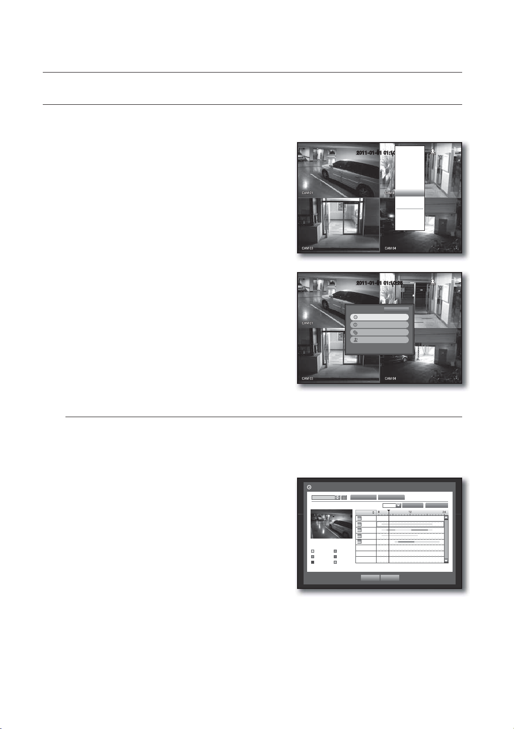
search & play
SEARCH
You can perform the search for recorded data by the time or by the search criteria such as an event.
You can access the <Search> menu directly in Live mode.
1. In Live mode, right-click any area of the screen.
The Live menu appears.
2. Select <Search>.
Or, press the [SEARCH] button on the remote control.
2011-01-01 01:10:25
Scene Mode
Spot Out
Audio Off
Freeze
Stop Alarm
Record
Play
Search
Backup
Main Menu
Shutdown
Hide Launcher
Logout
3. The Search menu appears.
2011-01-01 01:10:25
4. The search can be restricted by the Auto Delete function.
Refer to “Setting the Recording > Record Option”.
(Page
50)
Overlapped data : It only appears if there exists overlapped
M
data on a certain time, produced due to the change of DVR’s
Time Search
Event Search
Backup Search
Motion Search
Return
time setup. The latest data comes first, from <List0>.
It does not appear in <Backup Search>.
Time Search
You can search for recorded data of a desired time.
As the time to display may be different depending on the time zone and the DST standard time, the time of
data recorded in the same time can be displayed differently depending on time zone and DST settings.
Using the mouse may help make setup easier.
1. Select <Time Search> in the <Search> menu.
2. Select a date to search.
Refer to “Using the Calendar”. (Page 33)
3. The record data on the specific date will be listed.
The display bar is different according to the data type.
So check the data type for the color in the left pane.
4. Use direction buttons (
◄ ►
and press the [ENTER] button.
• Go to First : Moves to the earliest date.
• Go to Last : Moves to the most recent date.
• Time : Enter a time to perform the search or use the up/down button <
) to set the search criteria
Time Search
2011-01-01
2011/01/01 00:01:17
Standard Schedule
Motion Sensor
V.Loss Etc
>
> to select one.
Go to First Go to Last
Overlapped Data List1
00:01
All Data
CAM 01
CAM 02
CAM 03
CAM 04
Play Return
Zoom In Zoom Out
62_ search & play
Page 63
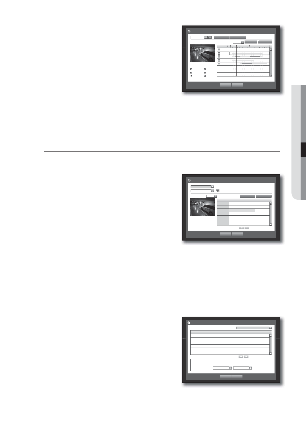
• Zoom In : The map enlarges in detail.
It will switch in the sequence of 24 hours - 16 hours - 8 hour
- 4 hours.
• Zoom Out : The map will switch in the reverse order of the
detailed mode above.
It will switch in the sequence of 4 hours - 8 hour - 16 hours
- 24 hours.
Double-click a desired time to zoom it in/out.
M
Time Search
2011-01-01
2011/01/01 00:01:17
Standard Schedule
Motion Sensor
V.Loss Etc
Go to First
Overlapped Data List1
00:01
All Data
CAM 01
CAM 02
CAM 03
CAM 04
Play Return
• Preview : Click <Channel> and select (click, drag) a time in
<Duration> to display a still image for the portion.
- If the selected channel does not contain any recorded data, it will be marked black.
5. Select a data item and click <Play>.
The screen switches to the data playback mode.
Event Search
You can search for events by the channel and play them.
Using the mouse may help make setup easier.
1. Select <Event Search> in the <Search> menu.
2. Use direction buttons (
◄ ►
) to set the search criteria
and press the [ENTER] button.
All record events on a specific date will be found. (Normal/
Schedule recording included)
• Date/Time Preview : If you select a data item in the list, the
still image of the selected data will be displayed in the left
preview pane.
• Event : Displays the type of the event that occurred.
3. Select a data item and click <Play>.
The screen switches to the event data playback mode.
Event Search
CAM 01
2011-01-01
Overlapped Data List1
2011/01/01 00:01:22
No. Date/Time Preview Event
3 02:47:54 ~ 02:48:59 Motion
2 00:39:06 ~ 00:40:30 Motion
1 00:01:22 ~ 00:02:28 Motion
Play Return
Go to Last
Zoom In Zoom Out
SEARCH & PLAY
Go to First Go to Last
Previous/Next Page
Backup Search
Searches for backup data in the connected backup device.
Only data in the format of DVR is included in the search.
Refer to <Type> in “Backup > Setting the Backup”. (Page 54)
Using the mouse may help make setup easier.
1. Select <Backup Search> in the <Search> menu.
2. Use direction buttons (
and press the [ENTER] button.
• Record Period : Displays the record period.
• Channel : Displays the recorded channel.
• Play Start Time : Select a time that you start playing.
3. Select a data item and click <Play>.
The screen switches to the backup data playback mode.
◄ ►
) to set the search criteria
Backup Search
No. Folder Name File Name
1 20110101 16190000
File Name 16190000 Channel 1
Record Period 2011-01-01 01:01:01 - 2011-01-01 01:01:10
Play Start Time 2011-01-01 01:01:01
USB:USB2FlashStorage
Previous/Next Page
Play Return
English _63
Page 64

search & play
Motion Search
If a motion is detected in each channel, you can set a desired area to perform the search.
You can use the mouse to select the related items.
1. Select <Motion Search> in the <Search> menu.
2. Use direction buttons (
◄ ►
) to set the search criteria
and press the [ENTER] button.
If you set the motion area to <Manual Area>, the <Setup>
button will be activated.
• Motion Region : Select an area to perform the search.
- All Area : Searches for all areas of the selected channel.
- Current Area : Searches for the motion area for each
channel specified in “Motion Detection >
Setting the Motion Detection Area”. (Page 52)
- Manual Area : You can set the motion area manually.
• Setup : The Setup button will be activated only if you have
set the motion area to Manual. Press this button to display
the area setting window.
• Date/Time : The Date/Time will be automatically set by the
hour, and the end time will be automatically set to one hour
later than the start time if it is set.
• Preview : Select a data item in the list to display the still
image of the item.
Motion Search
Channel CAM 01 Motion Region All Area
Date/Time 2011-01-01 03:41:18 2011-01-01 05:11:44
2011/01/01 01:01:30
Motion Region
CH1
Individual
Go to First Go to LastOverlapped Data List1
Apply to All CH
No. Start Time
7 01:01:30
6 01:01:25
5 01:01:20
4 01:01:15
3 01:01:10
2 01:01:05
1 01:01:01
Play Return
OK Cancel
Setup
Search
Previous/Next Page
3. Select a data item and click <Play>.
The screen switches to the motion data playback mode.
64_ search & play
Page 65

PLAYBACK
Play
You can play data stored in the HDD and backup a desired portion of the data.
Using the mouse may help make setup easier.
1. In Live mode, click <Play> in the right-click menu or
< > in the launcher menu, or press the Play button on
the remote control.
2. Use the up/down button () to select a menu.
For data search, refer to <Search>. (Page 62)
2011-01-01 01:10:25
Scene Mode
Spot Out
Audio Off
Freeze
Stop Alarm
Record
Play
Search
Backup
Main Menu
Shutdown
Hide Launcher
Logout
SEARCH & PLAY
3. Select a data item and click <Play> in the Search menu.
The selected data is played and the play launcher appears
on the screen.
If there is an existing data, <Play> will start immediately without
performing the search.
• Playback Information : Displays the date and time of the
current data in the top corner.
• Backup : Click <
time of backup; you can specify a backup area using the
mouse (yellow triangle).
Click <
> again to set the current time to the end time of
the backup and the “Backup Range” window appears.
- Type : Supports formats of DVR and SEC.
Refer to a list of formats in “Setting the Backup”.
54)
(Page
- Device : Select a backup device.
- Check Capacity : Enables you to check the capacity of the
selected storage device.
4. If you want to return to the Live screen in Play mode, click <
] button on the remote control.
[
> to set the current time to the start
2011-01-01 01:10:25
Backup Range
Start End
2011-01-01 00:01:06 2011-01-01 01:10:25
Device USB Storage Type DVR
Folder \20110101\ Filename 0001
Check capacity
Backup Cancel
> in the launcher menu or press the
Backup
Used
Fre
Change
REC
English _65
Page 66

search & play
Using the Playback Button
Part Names Functions
Play Timeline Indicates the current playback point, and can be used to move.
Skip Backward Moves backward by unit time.
b
c
Backward Fast
Play
Used for quick backward search while in Play.
REC
Backward Slow
Play
Step Backward Moves backward by one frame at a time.
Pause Stops playing the current video temporarily.
Stop Stops playback and moves to the live screen.
Step Forward Moves forward by one frame at a time.
Forward Slow
Play
Forward Fast
Play
Skip Forward Moves forward by unit time.
Return Return to the previous.
Audio
m
REC Records all channels in Live mode.
n
Used for backward frame-by-frame search while in PAUSE.
Ensured to play forward up to 4 channels simultaneously at a low speed.
In a split mode, the real time playback may not be supported, depending on the record
quality, resolution and number of channels. And some frame rates may be supported.
Used for quick forward playback.
Sets Audio ON/OFF.
If using both web view and DVR set simultaneously, the audio signal will be output from the
DVR set.
Partial Backup
Mode Switch Click a desired playback mode or press [MODE] to switch the screen mode in sequence.
66_ search & play
Begins backup of the selected section of the video being played, with the specified starting/
ending point.
Page 67

web viewer
INTRODUCING WEB VIEWER
What is Web Viewer?
Web Viewer allows remote access to your DVRs. You have
access to live video, archived video etc.
PRODUCT FEATURES
• Remote access from a standard browser
• Supports 1, 4 camera viewing formats (maximum of 4
cameras in the list).
• Gets JPEG, BMP format images to print and save to “Print
or Save JPEG, BMP format images”.
• Record video in AVI format-compatible with popular media
players. (needed the H.264 codec)
SYSTEM REQUIREMENTS
The following lists the minimum suggested hardware and operating system requirements needed to run the
Web Viewer.
Windows XP Professional
OS
Windows 2000
Windows Vista Home Basic / Premium
Windows 7
WEB VIEWER
Web Browser Internet Explorer 6.0.2900.2180 or higher
CPU
Memory 512 MB
Monitor High Color 16-bit 1024 x 768
HDD
Intel Pentium 4, 2 GHz
50 MB(Installation space required)
* Additional HDD space required for recording.
Recorded file size will vary depending on recording quality settings.
English _67
Page 68

web viewer
CONNECTING WEB VIEWER
1. Open your web browser and type the IP address or URL
of DVR into the URL address box.
The basic URL of the DVR is as following in case of MAC
M
address :
http://www.samsungipolis.com/User ID
You can also use registered URL which setups up in the Setup menu of your DVR.
2. Set the Admin ID and password same to those of the DVR
Admin.
For general users, enter the DVR user ID and password.
The default password can be exposed to a hacking thread so
J
it is recommended to change the password after installing the
product.
Note that the security and other related issues caused by the unchanged password shall be responsible for the user.
It allows up to 4 simultaneous access including the Admin and general users.
M
It does not allow multiple login of the Admin user.
Initial password of the Admin user is set to “4321”.
Password of the Admin and general users can be changed in <Permission Management> menu of the DVR.
Normal users should have set <Viewer> under <Permission Management> to “Use” before connecting to the
Web Viewer. (Page 37)
All settings are applied by the DVR’s settings.
3. Click <Install ActiveX Control…>.
Downloading Active-X control may take several minutes
according to the security settings on your PC.
4. Click <Install>.
68_ web viewer
Page 69

5. You may have “Windows Security Alert” that attempts to
block this with the Windows Firewall. In that case, click
<Unblock> to start Web Viewer.
6. Installation is complete.
Now you can see the main screen of Live Viewer.
USING LIVE VIEWER
WEB VIEWER
The Live Viewer screen consists of following :
This displays the IP address and the model name of the connected DVR.
b These menus consist of <LIVE>, <SEARCH>, <SETUP>, <ABOUT>.
c These buttons are used for the screen split and full screen mode.
Shows the IP address and model name of the connected DVR.
Select the format of OSD information that will be displayed on Live Viewer.
These buttons are used for sequence and changing the screen channel.
These buttons are used for capture, print, and save the image.
Shows the channel of the connected DVR.
This displays the screen for connected camera with DVR.
The resolution is set to 1024X768 pixels.
M
The initial split-screen mode is set according to the number of channels connected to DVR. You can change the
split-screen mode by clicking buttons for split-screen modes.
English _69
Page 70

web viewer
OSD INFORMATION DISPLAY
The channel number, video size, and IP address of the connected
DVR are displayed.
b The current date and time will be displayed according to the
selected time information display setting <DVR Time> or
<PC Time>.
c Alarm icon appears when alarm is issued.
It disappears when pressed the [ALARM] button of the DVR.
Motion icon appears when motion is detected.
It disappears when pressed the [ALARM] button of the DVR.
SPLIT-SCREEN
You can change the split mode by clicking each number icon.
SINGLE MODE QUAD MODE
• Click <
The screen displays the selected camera connected to the DVR in
“SINGLE MODE”.
• Click <
The screen displays the selected camera connected to the DVR in
“QUAD MODE”.
• Click <
The screen displays the selected camera connected to the DVR in
“FULL SCREEN MODE”.
Double clicking on the screen or pressing any button of the keyboard
returns to the previous mode.
> button.
> button.
> button.
70_ web viewer
Page 71

CONNECTED DVR
This displays the IP address and the status of the connecting DVR.
Connection failure message
M
No Response : Appears when the DVR does not respond.
Access Denied : Appears when the maximum number of users is exceeded.
The number of simultaneous connections are limited to 4.
Setting the display of the OSD time information
Select <DVR Time> or <PC Time> for the OSD time information display
setting.
• DVR Time : Based on the time of the connected DVR
• PC Time : Based on the time of the PC currently running the Web Viewer.
WEB VIEWER
CHANGING THE LIVE SCREEN MODE
• SEQUENCE : When this button is clicked, screens are switched at a
preset interval.
In SINGLE MODE, the channel numbers are sequentially switched from
1 to 4.
In QUAD MODE, the screen refreshes at the preset interval.
Preset interval (10 seconds)
• PREVIOUS : When this button is clicked, the previous screen appears.
In QUAD MODE, the screen is refreshed.
• NEXT : When this button is clicked, the next screen appears.
In SINGLE MODE, the channel numbers are sequentially switched from
1 to 4.
In QUAD MODE, the screen is refreshed.
English _71
Page 72

web viewer
SAVING THE LIVE SCREEN ON THE PC
• CAPTURE : Saves the current screen into a BMP or JPEG
file.
The default saving path is “C:\Program Files\Samsung\Dvr
M
Web Viewer\SnapShot\Live”. To change the saving path, click
<SAVE PATH (
want. For Windows Vista or 7, the saving path is “C:\users\
(user ID)\AppData\LocalLow\Samsung\DVR Web Viewer\
SnapShot\” by default.
The file is automatically named as following : “IP address_Port number_YYYYMMDD_HHMMSS_camera number_
index”
Ex) 192.168.1.200_554_20110414_093118_01_00
• PRINT : Prints out the selected screen out of the currently
displayed live screens. It also prints the IP address, time,
camera number and the current event status together.
)> button and then select the path you
• RECORD : Saves the current image on the screen and
saves it as a avi video file.
To record it, it is required at least 1GB of available space.
M
The default saving path is “C:\Program Files\Samsung\Dvr
Web Viewer\VideoClip\Live”. To change the saving path, click
<SAVE PATH ( )> button and then select the path you
want. For Windows Vista or 7, the saving path is “C:\users\
(user ID)\AppData\Local-Low\Samsung\DVR Web Viewer\VideoClip\”.
The file is automatically named as following : “IP address_Port number_YYYYMMDD_HHMMSS_camera number_
index”
Ex) 192.168.
For AVI Save, you need the H.264 codec for playing saved files.
HDD Minimum Free Size : During the recording, if there is no more capacity available in the HDD than set free space
will prompt with a popup message : “Cannot record due to insufficient disc space in the HDD”.
1.200_554_20110406_070455_01_00
CHANGING THE LIVE SCREEN CHANNEL
• Blue numbers : The channel connected to the current live
screen
• Gray numbers : The channel not connected to the current
live screen
If you select 4-split mode, the channel button for each of cameras
1 ~ 4 will turn blue.
72_ web viewer
Page 73

USING SEARCH VIEWER
The Search Viewer screen consists of following :
This displays the IP address and the model name of the connected DVR.
b There are 4 tabs available: <LIVE>, <SEARCH>, <SETUP>, <ABOUT>.
c Switch to a split mode.
Shows the IP address and model name of the connected DVR.
Select to turn the sound on/off.
These buttons are used for capture, print, and save the image.
This displays a calendar at which you can search the recorded video.
This displays a timeline at which you can search the recorded video by the time.
These buttons are used for controlling playback.
This displays the screen for playback of recorded video.
WEB VIEWER
<SEQUENCE>, <PREVIOUS>, <NEXT> buttons are not available in SEARCH menu.
M
During the DVR backup, you may have a trouble accessing CMS & Web Search.
English _73
Page 74

web viewer
SPLIT-SCREEN
You can change the split mode by clicking each number icon.
SINGLE MODE QUAD MODE
• Click <
The screen displays the selected camera connected to the DVR in
“SINGLE MODE”.
• Click <
The screen displays the selected camera connected to the DVR in
“QUAD MODE”.
> button.
> button.
CONNECTED DVR
The IP of the connected DVR will be displayed.
Connection failure message
M
No Response : Appears when the DVR does not respond.
Access Denied : Appears when the maximum number of users is exceeded.
The number of simultaneous connection is limited to 2.
74_ web viewer
Page 75
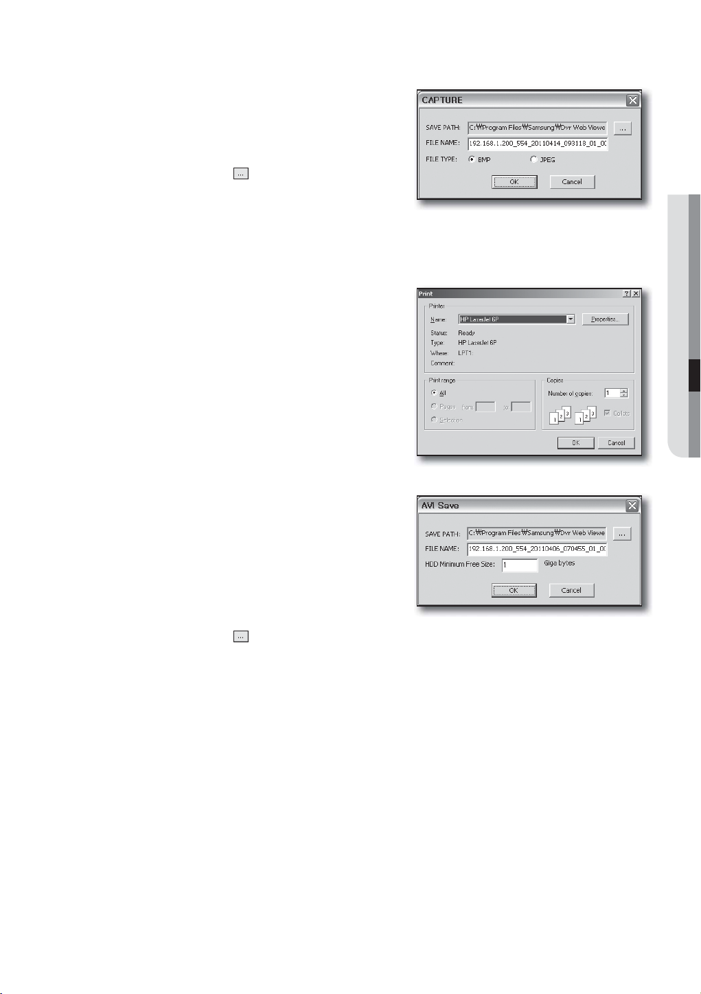
SAVING THE LIVE SCREEN ON THE PC
• CAPTURE : Saves the current screen into a BMP or JPEG
file.
The default saving path is “C:\Program Files\Samsung\Dvr
M
Web Viewer\SnapShot\Search”. To change the saving path,
click <SAVE PATH (
you want. For Windows Vista or 7, the saving path is “C:\
users\(user ID)\AppData\LocalLow\Samsung\DVR Web
Viewer\SnapShot\”.
The file is automatically named as following : “IP address_Port number_YYYYMMDD_HHMMSS_camera number_
index”
Ex) 192.168.
• PRINT : Print out the current screen. It also prints IP
address, time, camera number and current event state.
1.200_554_20110414_093118_01_00
)> button and then select the path
WEB VIEWER
• RECORD : While in playback, press this button saves the
video data of the selected channel as an AVI file. (It is saved
in the designated folder on your PC.)
To stop recording, click this button again.
To record it, it is required at least 1GB of available space.
M
The default saving path is “C:\Program Files\Samsung\Dvr
Web Viewer\VideoClip\Search”. To change the saving path,
click <SAVE PATH (
“C:\users\(user ID)\AppData\LocalLow\Samsung\DVR Web Viewer\VideoClip\”.
)> button and then select the path you want. For Windows Vista or 7, the saving path is
The file is automatically named as following : “IP address_Port number_YYYYMMDD_HHMMSS_camera number_
index”
Ex) 192.168.1.200_554_20110406_070455_01_00
For AVI save, you need the H.264 codec for playing saved files.
English _75
Page 76

web viewer
SEARCHING THE RECORDED VIDEO IN THE CALENDAR
If the video data has been recorded on a date, the date is
distinguished in green. If you click the date, the recorded video
information is displayed in the time line. When you click
<Today>, it will be synchronized with the system time (date) of
the current PC.
SEARCHING THE RECORDED VIDEO IN THE TIMELINE
It displays the recorded video data status on the DVR after a date is
selected. The normal mode displays the time ranging from 0 to 24 Hours
while the extension mode displays the time every 2 hours.
[Normal Mode]
• If you click <
• Each time line represents 1 hour.
> button, it changes to the extension mode.
[Extension Mode]
• If you click <
• Each time line represents 5 minutes.
The channels are ranging from CH01 to CH04.
M
> button, it changes to the normal mode.
76_ web viewer
Page 77
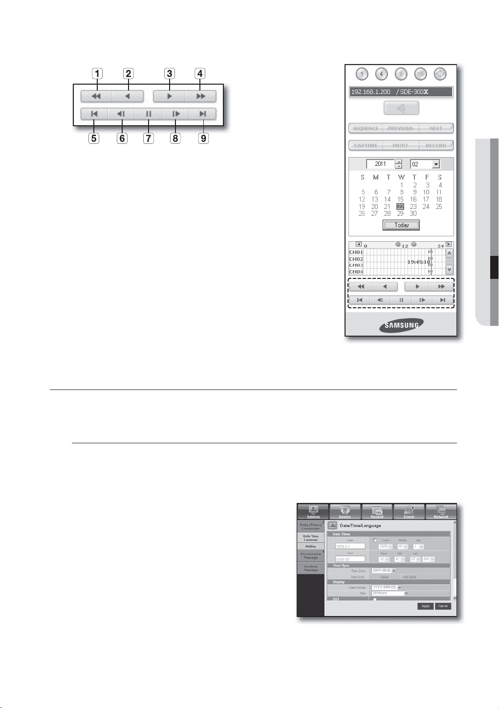
CONTROLLING PLAYBACK
Fast Backward : Reverse-plays faster(2x~64x).
b Reverse Play : Performs Reverse Play.
c Play : Performs playback.
Fast Forward : Plays faster(2x~64x).
Go to First :
Step Backward : Performs one step reverseplay by one frame.
Pause : Stops the playback temporarily.
Step Forward : Performs one step forward by one frame.
Go to Last : Moves the last time of recorded video in the time line.
Only the admin account can play the audio signal during the playback.
M
Moves the beginning time of recorded video in the time line.
If using both web view and DVR set simultaneously, the audio signal will be
output from the DVR set.
WEB VIEWER
VIEWER SETUP
You can configure the DVR settings remotely on the network.
To configure the DVR settings, click <Setup>.
System
You can configure the various settings of the DVR system.
Date/Time/Language
For more information, refer to <Date/Time/Language> in the <System Setup> menu. (Page 32)
1. Select <Date/Time/Language> in the System menu.
2. Configure the DVR settings according to your system
environment.
• Date/Time
Set the date and time.
English _77
Page 78
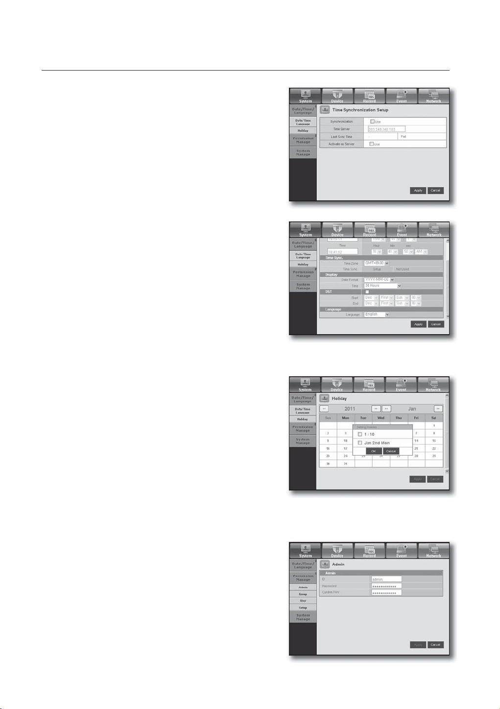
web viewer
• Time Synchronization Setup
Set the time synchronization.
• Display
Date Format : Set the date type.
Time : Select a time format to display on the screen.
• DST (Daylight Saving Time)
DST is displayed an hour ahead of the standard time of the
time zone.
• Language
Select a preferred language for the DVR.
Holiday
You can set specific dates to Holidays according to your
preferences.
For more information, refer to <Setting Holiday> in the
<System Setup> menu. (Page 33)
Permission Management
For more information, refer to <Permission Management> in the <System Setup> menu. (Page 34)
• Admin
You can change the admin ID or the password.
78_ web viewer
Page 79
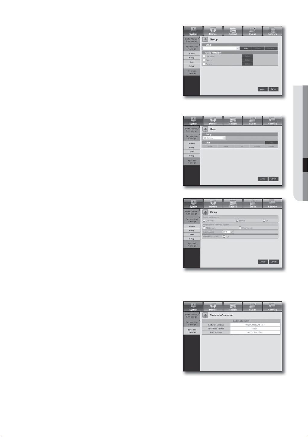
• Group
Users are classified into groups and the permission can be
set according to the group.
First of all, add a group.
• User
You can add, change or remove a user or users.
• Setup
You can set the user permission.
WEB VIEWER
System Management
For more information, refer to <System Management> in the <System Setup> menu. (Page 38)
• System Information
You can see information of the current system.
Check the software version, broadcast format and
MAC address.
English _79
Page 80

web viewer
Device
You can check a list of devices that are connected to the DVR and configure the necessary settings.
Click <Device> in the menu screen.
For more information, refer to “Setting the Device”. (Page 42)
Camera
• Camera
You can configure the settings of the camera that is
connected to the DVR.
Storage Device
You can check and change the settings of the storage device.
• Device
You will see a list of storage devices that are connected to the
DVR.
You can check the type, used/total, usage and status of the
device.
• HDD Alarm
You can set the alarm output channel and the alarm duration
for an error.
80_ web viewer
Page 81

Remote Device
Specify the use of remote control and the remote control ID so
that you can synchronize with the DVR.
Monitor
• Monitor
You can configure the monitoring screen settings and set the
output system.
WEB VIEWER
• Spot Out
With the monitor connected via the SPOT port, if there occurs
an event such as Sensor, Motion, or Alarm, you can select a
video output mode for external monitoring.
• Mode
You can switch between live mode and play mode.
English _81
Page 82
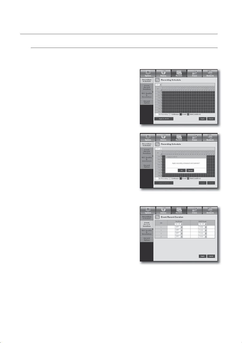
web viewer
Record
For more information, refer to <Setting the Recording>. (Page 48)
Recording Schedule
If you set a recording schedule for a specific date and time,
the recording will start at that specific time.
- Apply to All CH : Click <Apply to All CH> to display the
confirmation window.
Event Record Duration
You can set the start and end times of recording that will be
activated if an event occurs.
82_ web viewer
Page 83

REC Quality & Resolution
• Standard/Event
You can set the resolution, frame rate and recording quality for
each channel.
Record Option
You can set the Disk End Mode.
WEB VIEWER
Event
For more information, refer to <Setting the Event>. (Page 51)
Sensor Detection
You can set the sensor operation mode and the synchronized
camera as well as the alarm output type and the duration.
English _83
Page 84

web viewer
Motion Detection
You can set the motion detection mode and the sensitivity
as well as the alarm output type and the duration.
• Motion Region
Set the target motion detection area
Video Loss Detection
You can set the alarm output time if a video loss occurs.
Alarm Schedule
You can schedule the alarm output according to the day of
the week and the time.
The default setting is Event Sync, which activates the alarm
only if an event occurs.
84_ web viewer
Page 85

Network
For more information, refer to <Network Configuration>. (Page 55)
Connection
A remote user can access the DVR via the network to check
the current mode and the IP address.
• Connection
You can set the network connection route.
• Protocol
You can configure the protocol related settings.
WEB VIEWER
DDNS
You can check the DDNS settings.
Live Transfer
A remote user can set the images of the DVR.
• Live Transfer
A remote user can set the image resolution of the transferred
data.
English _85
Page 86

web viewer
Mailing Service
You can specify the SMTP server that sends a mail if an event
occurs and set the recipient group and users.
• SMTP
You can set the server that sends mails and specify if you use
the authentication process.
• Event
You can set the event interval and specify which events the
server sends mails for.
• Group
You can add a group to receive the mail if an event occurs
and set the permission to receive the event mail for each
group.
• Recipient
You can add a user or users who will receive the mail.
86_ web viewer
Page 87

ABOUT
Click <ABOUT>.
Displays the model name of connected DVR and the version
of Web Viewer.
MOBILE VIEWER
What is Mobile Viewer?
Mobile Viewer is management software that enables you to
connect to DVR (Digital Video Recorder) remotely and control
the video playback and PTZ operations (if confi gured) in real
time.
WEB VIEWER
Key Features
• Remote access via Smart phone
• 1-split and 4-split modes supported in Live Viewer
(However, search is not available).
• Switch channels using the touch-sensitive LCD panel
• Up to 4 channels supported
• Audio (wifi : O, 3G : X)
Supported Smart phone
• iPhone OS v4.2.1
• Android 2.1/ 2.2/2.3 (Galaxy S/S2)
For more information, refer to the user manual.
M
(http://www.samsungcctv.com)
1.X
English _87
Page 88
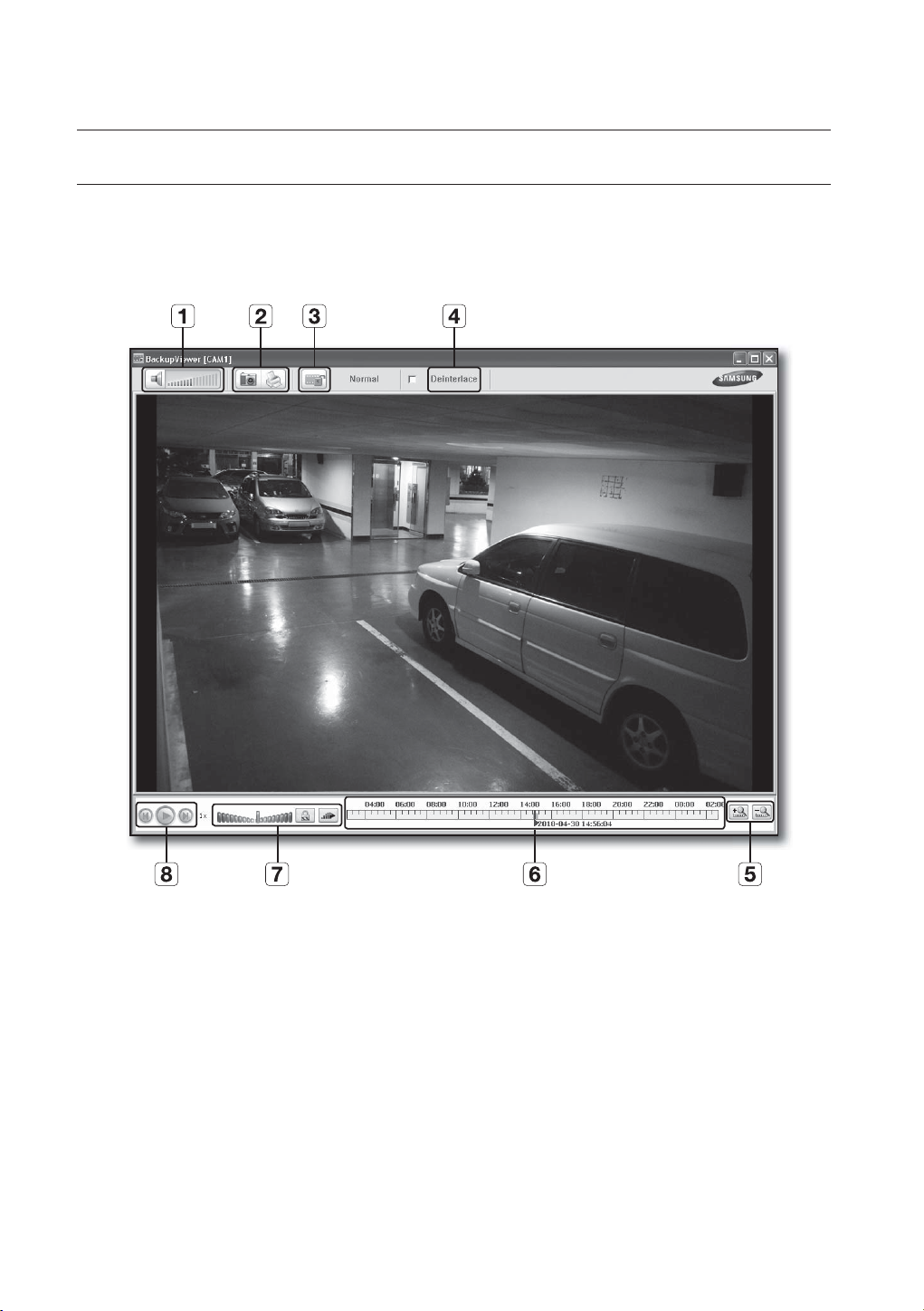
backup viewer
SEC BACKUP VIEWER
You can play a file that is backed up in the format of SEC.
Backup in the format of SEC will involve in generating two files: one for the backup data and one for the viewer.
If you run the backup file viewer, the backup data file will be automatically played.
Recommended System Requirements
PCs with a lower specification than the recommended below may not fully support forward/backward and
high-speed playback.
• OS : Windows XP professional, Windows Vista, Windows 7
• CPU : Intel Core2-Duo 2.4GHz or higher
• RAM : DDR PC-3200 1G or more
• VGA : Geforce 6200 or higher
88_ backup viewer
Page 89

Name Description
b
c
Audio
Screen Printout
File Tamper
Detection
Deinterlace You can enable the De-interlace function.
Zoom In/Out
/
/
A toggle button. Each time you press this button, the audio output will toggle
between activated and deactivated.
You can adjust the volume level from 0 to 100.
Saves the current screen as an image file. Supported file formats include
BMP and JPEG.
Prints out the current screen. You should have installed the appropriate
printer driver before you can print out the screen.
A toggle button. Each time you press this button, it will toggle between
activated and deactivated. The closed lock icon indicates activation of the file
tamper detection, which will blink the screen three times and stop playing if
an unauthorized manipulation of a data file is detected.
BACKUP VIEWER
A message of “The file is forged” will display in the menu bar.
Collapses the time range that is displayed on the range bar of the storage
time. You can collapse the range bar until the overall range is shortened to 24
hours.
Enlarges the time range that is displayed on the range bar of the storage
time. You can enlarge the range bar until the overall range is extended to 1
minute.
Display of storage time range
Speed
Play
Displays the time range of a stored video file.
You can move the gridline of the range bar to select a time point to play.
A toggle button; each time you press this button, the "Slow Playback" icon
changes its color to display it’s activated/deactivated. If it is activated, you
can use the play speed control to adjust the play speed up to x1/16 forward
and backward respectively, whereas if deactivated, you can adjust up to x16
forward and backward.
A toggle button; each time you press this button, the "Lock Speed" icon
changes its color to display it’s activated/deactivated.
If activated, the adjusted speed will be kept even if you release the mouse on
the speed bar. If deactivated, the adjusted speed will be applied only while
you use the mouse to hold the adjusted speed, and if you release the mouse,
the speed will restore to x1.
You can adjust the play speed up to x16 forward and backward respectively,
which varies according to the frame rate per second of the source.
Fast playback maximum is limited to x2 for footages recorded at 20 ~ 30 fps
(frames per second), x4 for 11 ~ 19 fps, x8 for 6 ~ 10 fps, and x16 for footages
recorded at slower than 6
Displays the next frame. This is available only if the playback is stopped.
A toggle button. Press it once to start playing the video and switch the button
mode to 'Pause', and press it again to switch the button mode to Play and
stop playing temporarily.
fps.
Displays the previous frame. This is available only if the playback is stopped.
English _89
Page 90

appendix
PRODUCT SPECIFICATION (CAMERA)
Item
Electrical
Input Voltage DC 12V(by UTP)
Power Consumption 2.6W
Video
Imaging Device MT9V138
Total Pixels 680 x 512
Scanning System Interlace
Synchronization Internal
Frequency
Horizontal Resolution 520TVL
Min. Illumination
S/N Ratio (Y Signal) 46dB
UTP
Lens
Focus Length
Max.Aperture Ratio 2
Angular Field of View
Operational
Shutter Mode Auto (Rolling Shutter)
Gain Control Auto
White Balance Auto (3200°K~6500°K)
Digital Noise Reduction Auto
Day & Night Auto
Night-Visibility 15m (20EA)
SEB-1005R N SEB-1005R P SEB-1007R N SEB-1007R P
H: 15,734 Hz H : 15,625 Hz H: 15,734 Hz H : 15,625 Hz
V: 59.94 Hz V : 50 Hz V: 59.94 Hz V : 50 Hz
OLux (IR-LED)
Built-in UTP TX
Maximum Transmission Length: 200m (UTP CAT 5e,
Balanced Differential Impedance: 100 ohm
3.6mm
H: 56˚
V: 42˚
Details
all of 8 pins are used)
90_ appendix
Page 91

Item
Environmental
Operating Temperature/
Humidity
Mechanical
Dimension (W x H x D)
Weight 300g 115g
SEB-1005R N SEB-1005R P SEB-1007R N SEB-1007R P
0°C ~ +40°C (+32°F ~ +104°F) / 20% ~ 85% RH
W65.5 X H65.5 X D94.6 (2.58 X 2.58 X 3.72 inch)
Details
W59.1 X H59.1 X D72 (2.33 X 2.33 X 2.83 inch)
APPENDIX
English _91
Page 92

appendix
PRODUCT SPECIFICATION
Item
Video
Live
Performance
Operating System Embedded Linux
Recording
Search & Playback
Network
Smartphone SmartPhone Support
Storage
Inputs 4 UTP Line(CH1~CH4)
Resolution 704x480 NTSC, 704x576 PAL
Frame rate 30
Resolution 704x480 NTSC, 704x576 PAL
Multi Screen display 1, 4, PIP
Compression H.264
Record Rate
Mode
Overwrite modes Continuous
Pre-Alarm Off / 5sec
Post-Alarm Up to 6 hour. (5, 10, 20, 30 sec, 1, 3, 5, 10, 20 min,1, 2, 3, 4, 5, 6 hour)
Search mode
Playback function Fast Forward/Backward, Slow Forward/Backward, Step Forward/Backward
Transmission speed
Bandwidth
Bandwidth control
Stream H.264(CIF)
Maximum No. of remote
users
Protocol support TCP/IP, DHCP, PPPoE, SMTP, NTP, HTTP, DDNS, RTP, RTSP
Monitoring Smart viewer, Webviewer, Mobile Viewer
Internal HDD 500GB SATA HDD 1TB SATA HDD
External HDD –
DVD Writer (Back-up) –
USB (Back-up) 2 USB Ports
File Forma (Back-up) BU(DVR Player), EXE(Include Player)
fps NTSC, 25fps PAL
NTSC : Up to 30
NTSC : Up to 60
NTSC : Up to 120
NTSC : Manual, Schedule, Event, Time Laps
PAL : Manual, Schedule, Event, Time Laps
Date/time, Event, Back up, Motion
100 / 120fps
Up to (4)Mbps, Unlimited(4M)/2/1.5/1 Mbps/800/600/500/400/300/200/
100/50 kbps
Automatic
Search(2) / Live Unicast(4) / Live Multicast(20)
Details
SDE-3001 SDE-3003
fps @ 704x480 / PAL : Up to 25fps @ 704x576
fps @ 704x240 / PAL : Up to 50fps @ 704x288
fps @ 352x240 / PAL : Up to 100fps @ 352x288
92_ appendix
Page 93
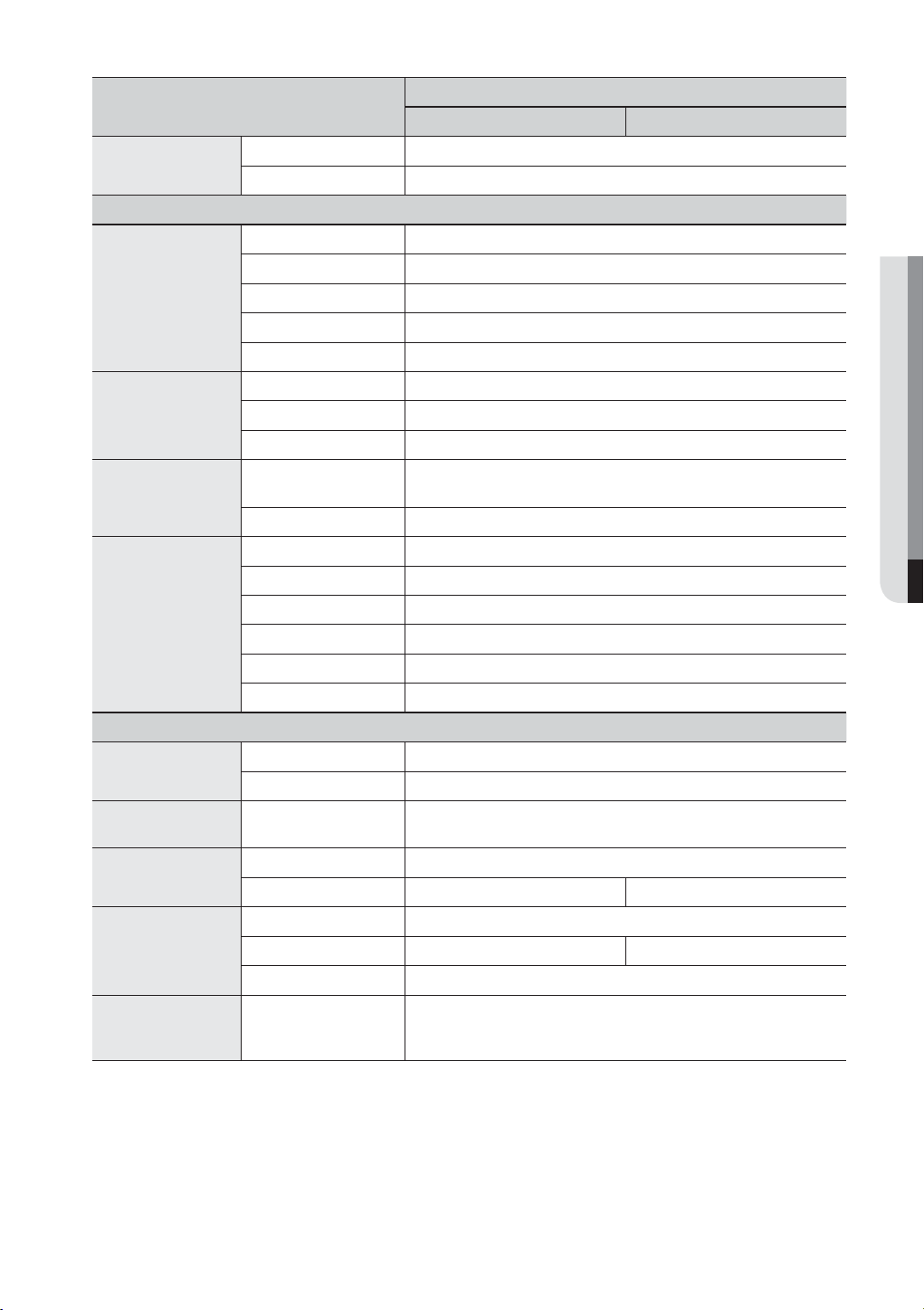
Security
Interface
Monitors
Audio
Alarm
Connections
General
Electrical
Environmental
Mechanical (Set)
Mechanical (Package)
Lauguage
Item
Password Protection 1 Admin, 10 Group,
Data Authentication Watermark
VGA Analog RGB 1024x768 resolution(BNC or VGA selected in booting.)
HDMI –
Main Composite BNC, 1 Vp-p, 75 ohm
Spot Composite –
Loop Outputs –
Inputs/Output 1 Line in(CH1) /
Compression G.711
Sampling rate 8KHz
Inputs/Outputs
Remote notification Notification via e-mail
Ethernet 1 RJ45 10/100 Base-T
Serial interface –
USB
e-SATA –
Application Supoort Mouse
Protocol support –
Input Voltage/Current 100 to 240 VAC ±10%; 50/60 Hz, Autoranging
Power consumption
Operating Temperature/
Humidity
Dimension (W x H x D) W255 X H50 X D213
Weight (With hard disks)
Dimension (W x H x D)
Weight (With hard disks) 6.06kg 7.03kg
Rack mount kit –
Terminal 4 inputs (NO/NC) / Terminal 1 relay outputs (NO/NC),
Rating :
USB 2.0, 2 ports (Front/Rear)
ADP-4812 Adaptor (1EA), 48W
0°C ~ +40°C (+32°F ~ +104°F) / 20% ~ 85%RH
1.58kg 1.73kg
W406 X H218 X D338mm (15.98 X 8.58 X 13.31 inch)
English, Spanish, French, German, Italian, Polish, Portuguese, Russian,
Turkish, Japanese, Czech, Swedish, Danish, Korean, Chinese, Netherland,
Thai, Romanian, Serbian, Croatian, Hungarian, Greek
SDE-3001 SDE-3003
10 User per 1 Group
1 line out(RCA)
24V DC 1A, 125VAC/0.5A
(1EA), Remote Controller
mm
Details
(10.04 X 1.97 X 8.39 inch)
APPENDIX
English _93
Page 94
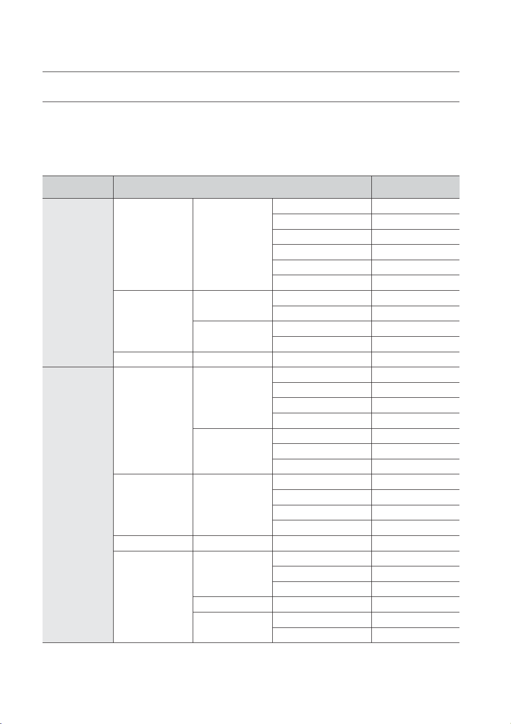
appendix
DEFAULT SETTING
This returns the factory default settings.
The settings are made as follows;
• Use System/Load Factory Default in MENU
The default password can be exposed to a hacking thread so it is recommended to change the password after installing the product.
Note that the security and other related issues caused by the unchanged password shall be responsible for the user.
Category Details Factory Default
Date YYYY-MM-DD
Time Format 24 hours
Time Zone GMT+09:00
Time Synchronize OFF
DST OFF
Language English
ID admin
New Password 4321
Restricted Access Backup
Auto Logout OFF
Video ON
Audio OFF
CH Name CAM 01 ~ CAM 04
SEQ-Dwell Time 5sec
Brightness 50
Contrast 50
Color 50
Check Alarm Output Port OFF
Duration OFF
Replace Alarm Output Port OFF
Duration OFF
Event Display OFF
Display All
Display Position Setup 30
Live Mode ALL
Play Mode ALL
System Settings
Device
Date/Time/Language Date/Time/Language
Admin
Permission
Management
Setting
System Management System Information Broadcast Format NTSC/PAL
Camera
Camera
Screen Setup
Storage Device HDD Alarm
Remote Device Remote Device Remote Control ON(00)
Monitor
Monitor
Spot Out Spot Out 1 CH1 ~ CH4
Mode
94_ appendix
Page 95
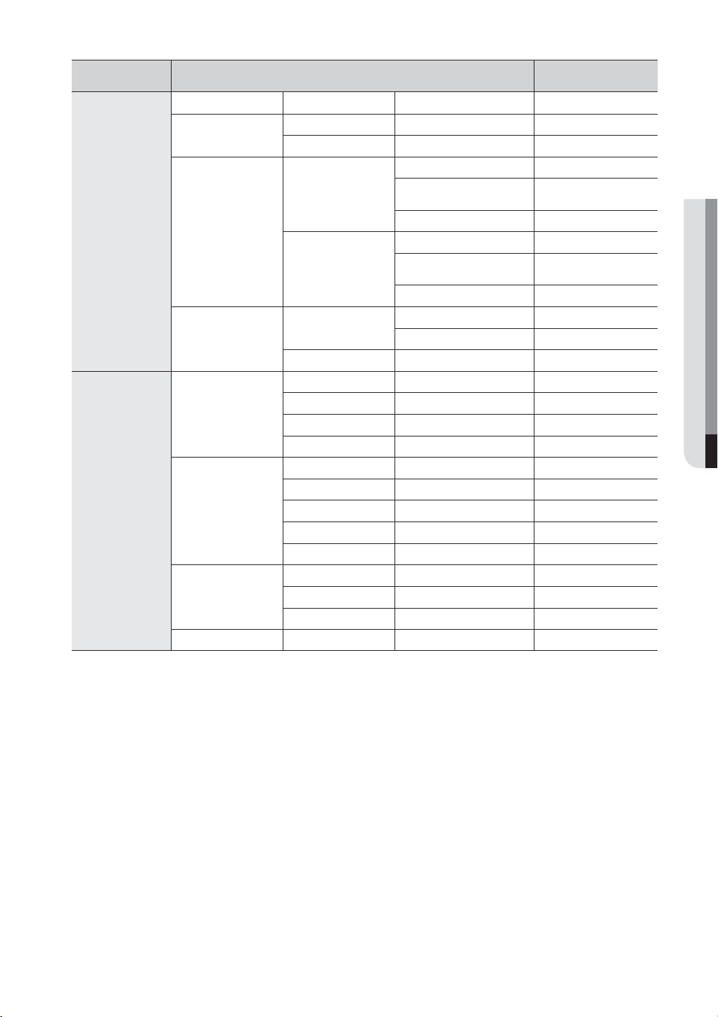
Category Details Factory Default
Recording Schedule Channel 1 Event
PRE Event OFF
POST Event 1 min
Resolution CIF(S)
Normal Recording
Event
Disk End Mode
Auto Delete OFF
Sensor Operation OFF
Camera Camera No.
Alarm None
Duration 10 sec
Mode OFF
Sensitivity Level10(high)
Alarm None
Duration 10 sec
Motion Region All Area
Video Loss State OFF
Alarm None
Duration 10 sec
Frame Rate
Record Quality Level 4
Resolution 4CIF(L)
Frame Rate
Record Quality Level 4
Setup Overwrite
Disk End Beep OFF
NTSC:
PAL: 6.2
NTSC:
PAL: 6.2
7 fps,
fps
7 fps,
fps
Recording
Event
Event Record
Duration
REC Quality/
Resolution
Record Option
Sensor Detection
Motion Detection
Video Loss Detection
Alarm Schedule Alarm1 Event Sync
APPENDIX
English _95
Page 96

appendix
Category Details Factory Default
Connection Mode Static IP
Bandwidth 2Mbps
IP 192.168.1.200
Gateway 192.168.1.1
Subnet Mask 255.255.255.0
DNS 168.126.63.1
Protocol Type TCP
Port (TCP) 554~558
Webviewer Port 80
Server OFF
Port 25
Use Authentication OFF
Secure Transfer
Event Interval 10 min
Use Event Transfer OFF
Group OFF
Recipient Permission OFF
Network
Connection
Connection Mode
Protocol
DDNS DDNS Site OFF
Live Transfer
Mailing Service
Resolution CIF(S)
Quality Low
SMTP
Event
Group
Never
96_ appendix
Page 97

TROUBLESHOOTING
Symptom Countermeasures
The system does not turn on and the indicator on the
front panel does not work at all.
Some channels display just a black screen even if
they receive video sources.
If I press the [REC] button on the front panel, the
REC indicator does not flash, nor the player start
recording.
The screen displays the logo image repeatedly. This may occur from a problem with the main board, or the related
The Channel button does not work on the Live
screen.
The cursor will not move to the Start button when I
start the calendar search.
Check if the power supply system is properly connected.
Check the system for the input voltage from the power source.
If the problem persists even after you have taken the above actions,
check the power supplier and replace it with a new one if neccessary.
Check if the camera connected to the system properly displays the
image. Sometimes, this problem may occur on a camera that is not
properly connected to the video source.
Check if the camera is properly supplied with power.
Sometimes, this problem may occur on a channel with weak video
signal from a video distributor that is connected to multiple systems. In
this case, input the video source of the camera directly into the DVR.
This may find the cause and solve the problem.
Check if there is a free space on the HDD for the recording.
Check if the record mode is set to ON in the record mode setting.
software is corrupt.
Contact the nearest service center for more information.
The Channel button does not work if the current screen is in the event
monitoring mode.
In the event monitoring screen, press the [ALARM] button to exit the
screen and select a channel.
Check if the channel and the date that you want to play are marked
with the V symbol.
Both channel and date should be checked before you can start playing
with the Start button.
APPENDIX
When the alarm sounds, I press the [ALARM] button
on the
Remote Control to release the alarm but it
does not work. The alarm persists and I could not set
it off in any way.
A message of “Need to reset date/time.” Is displayed
on the screen.
The time bar is not displayed in Search mode. The timeline can switch between normal and extension mode.
The “NO HDD” icon and an error message are
displayed.
Press the [MENU] button to release the alarm in the following way:
1) To release the event monitoring mode : Monitoring Mode – set the
duration of the event monitoring to Off.
2) To release the alarm sound : Event Record Mode - Alarm (Motion
Detection/Video Loss) – deactivate the alarm sound.
3) To release the event : Event Record Mode - Alarm (Motion Detection/
Video Loss) – set the mode to Off.
This message is displayed if there occurs a problem with the time
setting of the internal clock or an error in the clock itself.
Contact the retailer or the service center for more information.
In extension mode, the time bar may not be displayed in the current
timeline. Switch to normal mode or use the left or right button to
navigate through the time bar.
Check the HDD for connection. If the problem persists in a normal
condition, contact the nearest service center to have the HDD checked
by the service personnel.
English _97
Page 98

appendix
Symptom Countermeasures
I have connected an external storage device (external
SATA HDD) to the DVR but the DVR seems not to
recognize it.
If I press the ESC key in full screen mode of the
WebViewer, the system does not switch to a normal
split mode.
I found it difficult to configure the network settings if
using the default search, backup and router settings.
I forgot the password.
Backup data is just not played by the PC or DVR. When you are backing up data, you have choices about the player
My player does not switch to Live mode while in
playback.
Recording does not work. If your player does not display a Live image at all, that indicates
See the compatibility list of external storage devices to check if the
connected device is supported by the DVR.
For the compatibility list, contact the retailer where you purchased the
DVR.
Press the ALT+TAB keys to select ‘ACTIVE MOVIE’ and press the ESC
key again. The system will switch to a normal split mode.
For more information, refer to the user manual.
If you want to check the basics of the product for a quick start, refer to
the quick start guide (backup, search).
Contact the DVR administrator for help.
either: PC or DVR. Make your selection before proceeding.
If you are using the PC to play the data, the format of the backup file
should be either SEC.
If you are using the DVR for this purpose, formatting backup files should
be done by the DVR.
Press the Stop [@] button on the DVR or the remote control, or click the
[
] icon on the launcher to switch to Live mode.
recording does not work so first check if you see an image on the
screen.
Recording does not work if the recording settings are not properly
configured.
1) Manual Record: Press the [REC] button on the remote control to start
recording.
2) Scheduled Record: Specify a desired time in Menu – Record Recording Schedule. Recording will start at the specified time.
-<Continuous> Record: Recording will proceed in any conditions
at the specified time.
-<Event> Record: When an event occurs, recording will perform
only if the event is of alarm, motion detection and video loss.
If there is no event found, recording will not perform.
-<Continuous / Event> Record: If there is no event found,
Continuous recording will perform. Whereas, if an event occurs,
Event recording will perform.
The image quality of the recording data is not good. Increase the resolution and quality level in Menu – Record – Quality /
Resolution.
1) Resolution: Select a bigger size when specifying the recording size.
(4CIF> 2CIF>CIF)
The recording image in the CIF format shows a deteriorated quality
as it is enlarged from a small-sized image.
2) Record Quality: Specify a bigger level for the recording quality.
If you increase the resolution and the recording quality, the data size
increases accordingly. So the HDD will be filled faster. Overwriting will
overwrite the existing data so recording will proceed at a shorter
interval.
98_ appendix
Page 99

OPEN SOURCE LICENSE REPORT ON THE PRODUCT
The software included in this product contains copyrighted software that is licensed under the GPL/LGPL. You may
obtain the complete Corresponding Source code from us for a period of three years after our last shipment of this
product by sending email to help.cctv@samsung.com
If you want to obtain the complete Corresponding Source code in the physical medium such as CD-ROM, the cost
of physically performing source distribution might be charged.
• GPL Software : linux kernel, Sysvinit, dosfstoOls, wget, msmtp, busybox, cdrtools, dvd+rw-tools, iconv, smartctl,
uboot, minicom, openssl, bash, lm_sensors
• LGPL Software : glibc, vmstat, inetutils
• OpenSSL License : OpenSSL
GNU GENERAL PUBLIC LICENSE
Version 2, June 1991
Copyright (C) 1989, 1991 Free Software Foundation, Inc.
51 Franklin Street, Fifth Floor, Boston, MA 02110-1301,
USA
Everyone is permitted to copy and distribute verbatim
copies of this license document, but changing it is not
allowed.
Preamble
The licenses for most software are designed to take
away your freedom to share and change it. By contrast,
the GNU General Public License is intended to
guarantee your freedom to share and change free
software to make sure the software is free for all its
users. This General Public License applies to most of
the Free Software Foundation’s software and to any
other program whose authors commit to using it.
(Some other Free Software Foundation software is
covered by the GNU Lesser General Public License
instead.) You can apply it to your programs, too.
When we speak of free software, we are referring to
freedom, not price. Our General Public Licenses are
designed to make sure that you have the freedom to
distribute copies of free software (and charge for this
service if you wish), that you receive source code or can
get it if you want it, that you can change the software or
use pieces of it in new free programs; and that you
know you can do these things.
To protect your rights, we need to make restrictions
that forbid anyone to deny you these rights or to ask
you to surrender the rights. These restrictions translate
to certain responsibilities for you if you distribute copies
of the software, or if you modify it.
For example, if you distribute copies of such a program,
whether gratis or for a fee, you must give the recipients
all the rights that you have. You must make sure that
they, too, receive or can get the source code. And you
must show them these terms so they know their rights.
We protect your rights with two steps:
(1) copyright the software, and (2) offer you this license
which gives you legal permission to copy, distribute
and/or modify the software.
Also, for each author’s protection and ours, we want to
make certain that everyone understands that there is no
warranty for this free software. If the software is
modified by someone else and passed on, we want its
recipients to know that what they have is not the
original, so that any problems introduced by others will
not reflect on the original authors’ reputations.
Finally, any free program is threatened constantly by
software patents. We wish to avoid the danger that
redistributors of a free program will individually obtain
patent licenses, in effect making the program
proprietary. To prevent this, we have made it clear that
any patent must be licensed for everyone’s free use or
not licensed at all. The precise terms and conditions for
copying, distribution and modification follow.
TERMS AND CONDITIONS FOR
COPYING, DISTRIBUTION AND
MODIFICATION
Version 2, June 1991
Copyright (C) 1989, 1991 Free Software Foundation, Inc.
51 Franklin S
0. This License applies to any program or other work
which contains a notice placed by the copyright holder
saying it may be distributed under the terms of this
General Public License. The “Program”, below, refers to
any such program or work, and a “work based on the
Program” means either the Program or any derivative
work under copyright law: that is to say, a work
containing the Program or a portion of it, either verbatim
or with modifications and/or translated into another
language. (Hereinafter, translation is included without
limitation in the term “modification”.) Each licensee is
addressed as “you”.
Activities other than copying, distribution and
modification are not covered by this License; they are
outside its scope. The act of running the Program is not
restricted, and the output from the Program is covered
only if its contents constitute a work based on the
Program (independent of having been made by running
the Program). Whether that is true depends on what the
Program does.
1. You may copy and distribute verbatim copies of the
Program’s source code as you receive it, in any
medium, provided that you conspicuously and
appropriately publish on each copy an appropriate
copyright notice and disclaimer of warranty; keep intact
all the notices that refer to this License and to the
absence of any warranty; and give any other recipients
Page 100

of the Program a copy of this License along with the
Program.
You may charge a fee for the physical act of transferring
a copy, and you may at your option offer warranty
protection in exchange for a fee.
2. You may modify your copy or copies of the Program
or any portion of it, thus forming a work based on the
Program, and copy and distribute such modifications or
work under the terms of Section 1 above, provided that
you also meet all of these conditions:
a) You must cause the modified files to carry
prominent notices stating that you changed the
files and the date of any change.
b) You must cause any work that you distribute or
publish, that in whole or in part contains or is
derived from the Program or any part thereof, to
be licensed as a whole at no charge to all third
parties under the terms of this License.
c) If the modified program normally reads commands
interactively when run, you must cause it, when
started running for such interactive use in the
most ordinary way, to print or display an
announcement including an appropriate copyright
notice and a notice that there is no warranty (or
else, saying that you provide a warranty) and that
users may redistribute the program under these
conditions, and telling the user how to view a copy
of this License. (Exception: if the Program itself is
interactive but does not normally print such an
announcement, your work based on the Program
is not required to print an announcement.)
These requirements apply to the modified work as a
whole. If identifiable sections of that work are not
derived from the Program, and can be reasonably
considered independent and separate works in
themselves, then this License, and its terms, do not
apply to those sections when you distribute them as
separate works. But when you distribute the same
sections as part of a whole which is a work based on
the Program, the distribution of the whole must be on
the terms of this License, whose permissions for other
licensees extend to the entire whole, and thus to each
and every part regardless of who wrote it.
Thus, it is not the intent of this section to claim rights or
contest your rights to work written entirely by you; rather,
the intent is to exercise the right to control the distribution
of derivative or collective works based on the Program.
In addition, mere aggregation of another work not
based on the Program with the Program (or with a work
based on the Program) on a volume of a storage or
distribution medium does not bring the other work
under the scope of this License.
3. You may copy and distribute the Program (or a work
based on it, under Section 2) in object code or
executable form under the terms of Sections 1 and 2
above provided that you also do one of the following:
a) Accompany it with the complete corresponding
machine-readable source code, which must be
distributed under the terms of Sections 1 and 2
above on a medium customarily used for software
interchange; or,
b) Accompany it with a written offer, valid for at least
three years, to give any third party, for a charge no
more than your cost of physically performing
source distribution, a complete machine-readable
copy of the corresponding source code, to be
distributed under the terms of Sections 1 and 2
above on a medium customarily used for software
interchange; or,
c) Accompany it with the information you received as
to the offer to distribute corresponding source
code. (This alternative is allowed only for
noncommercial distribution and only if you
received the program in object code or executable
form with such an offer, in accord with Subsection
b above.)
The source code for a work means the preferred form
of the work for making modifications to it. For an
executable work, complete source code means all the
source code for all modules it contains, plus any
associated interface definition files, plus the scripts used
to control compilation and installation of the executable.
However, as a special exception, the source code
distributed need not include anything that is normally
distributed (in either source or binary form) with the
major components (compiler, kernel, and so on) of the
operating system on which the executable runs, unless
that component itself accompanies the executable.
If distribution of executable or object code is made by
offering access to copy from a designated place, then
offering equivalent access to copy the source code
from the same place counts as distribution of the
source code, even though third parties are not
compelled to copy the source along with the object
code.
4. You may not copy, modify, sublicense, or distribute
the Program except as expressly provided under this
License. Any attempt otherwise to copy, modify,
sublicense or distribute the Program is void, and will
automatically terminate your rights under this License.
However, parties who have received copies, or rights,
from you under this License will not have their licenses
terminated so long as such parties remain in full
compliance.
5. You are not required to accept this License, since
you have not signed it. However, nothing else grants
you permission to modify or distribute the Program or
its derivative works. These actions are prohibited by law
if you do not accept this License. Therefore, by
modifying or distributing the Program (or any work
based on the Program), you indicate your acceptance
of this License to do so, and all its terms and conditions
for copying, distributing or modifying the Program or
works based on it.
6. Each time you redistribute the Program (or any work
based on the Program), the recipient automatically
receives a license from the original licensor to copy,
distribute or modify the Program subject to these terms
and conditions. You may not impose any further
restrictions on the recipients’ exercise of the rights
granted herein. You are not responsible for enforcing
compliance by third parties to this License.
 Loading...