

Page 1

PEBBLE
LCD-Monitor
Chassis : LPE20BS
LPE22BS
Model : 2032BW
2232BW
Manual
SERVICE
TFT-LCD Monitor Contens
1. Precautions
2. Product specications
Disassembly and Reassemble
3.
Troubleshooting
4.
Exploded View & Part List
5.
Wiring Diagram
6.
Schematic Diagram
7.
2032BW / 2232BW
Refer to the service manual in the GSPN (see the rear cover) for the more information.
Page 2

Contents
1. Precautions ..............................................................................................................1-1
1-1. Safety Precautions .........................................................................................................1-1
1-2. Servicing Precautions .....................................................................................................1-2
1-3. Static Electricity Precautions ..........................................................................................1-2
1-4. Installation Precautions ..................................................................................................1-3
2. Product specications ............................................................................................2-1
2-1. Feature & Specications .................................................................................................2-1
2-2. Spec Comparison to the Old Models ..............................................................................2-2
2-3. Accessories ....................................................................................................................2-3
2-4. Accessories (Sold separately) ........................................................................................2-3
3. Disassembly and Reassemble ............................................................................... 3-1
3-1. Disassembly ...................................................................................................................3-1
3-2. Stand ....................................................................................
4. Troubleshooting ......................................................................................................4-1
4-1. Troubleshooting ..............................................................................................................4-1
4-2. No Power ........................................................................................................................4-2
4-3. No Video (Analog) ..........................................................................................................4-3
4-4. No Video (DVI) ................................................................................................................4-5
4-5. Faults and Corrective Actions .........................................................................................4-7
4-6. Adjustment ......................................................................................................................4-8
..........................................3-4
5. Exploded View and Parts List ................................................................................ 5-1
5-1. Exploded View ................................................................................................................5-1
5-2. LS20PEBSFV/EDC Parts List ........................................................................................5-3
5-3. LS22PEBSFV/EDC Parts List ......................................................................................5-10
6. Wiring Diagram ........................................................................................................6-1
6-1. Wiring Diagram ...............................................................................................................6-1
6-2. Connector Functions ......................................................................................................6-3
6-3. Cables ............................................................................................................................6-3
7. Schematic Diagram ................................................................................................. 7-1
7-1. Circuit Descriptions .........................................................................................................7-1
7-2. Schematic Diagrams ...................................................................................
...................7-2
Page 3

GSPN (Global Service Partner Network)
Area Web Site
North America http://service.samsungportal.com
America http://latin.samsungportal.com
Latin
CIS http://cis.samsungportal.com
Europe http://europe.samsungportal.com
China http://china.samsungportal.com
Asia http://asia.samsungportal.com
Mideast
This
Any unauthorized use of Manual can be punished under applicable
International and/or domestic law.
& Africa http://mea.samsungportal.com
Service Manual is a property of Samsung Electronics Co.,Ltd.
© 2007 Samsung Electronics Co.,Ltd.
All rights reserved.
Printed in Korea
P/N: BN82-00138Y-00
Page 4
1. Precautions
1. Precautions
1-1. Safety Precautions
Follow these safety, servicing and ESD precautions to prevent damage and to protect against potential hazards such as
electrical shock.
1-1-1. Warnings
For continued safety, do not attempt to modify the circuit board.
1.
Disconnect the AC power and DC power jack before servicing.
2.
1-1-2. Servicing the LCD Monitor
When servicing the LCD Monitor, Disconnect the AC line cord from the AC outlet.
1.
It is essential that service technicians have an accurate voltage meter available at all times. Check the calibration of
2.
this meter periodically.
1-1-3. Fire and Shock Hazard
Before returning the monitor to the user, perform the following safety checks:
Inspect each lead dress to make certain that the leads are not pinched or that hardware is not lodged between the
1.
chassis and other metal parts in the monitor.
Inspect all protective devices such as nonmetallic control knobs, insulating materials, cabinet backs, adjustment and
2.
compartment covers or shields, isolation resistorcapacitor networks, mechanical insulators, etc.
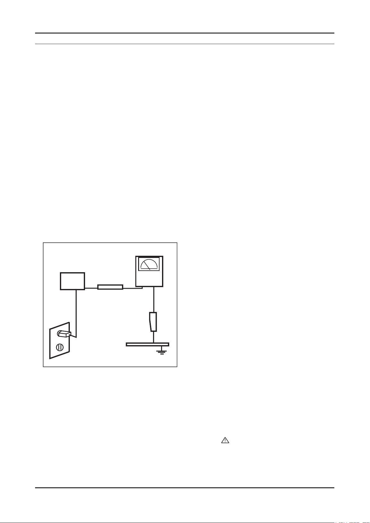
Leakage Current Hot Check (Figure 1-1):
3.
WARNING : Do not use an isolation transformer during this test.
Use a leakage current tester or a metering system that complies with American National Standards Institute (ANSI
C101.1, Leakage Current for Appliances), and Underwriters Laboratories (UL Publication UL1410, 59.7).
(READING SHOULD)
NOT BE ABOVE 0.5mA
DEVICE
UNDER
TEST
TEST ALL
EXPOSED METAL
SURFACES
2-WIRE CORD
*ALSO TEST WITH
PLUG REVERSED
(USING AC ADAPTER
PLUG AS REQUIRED)
With the unit completely reassembled, plug the AC line cord directly into a 120V AC outlet. With the unit’s AC switch
4.
LEAKAGE
CURRENT
TESTER
EARTH
GROUND
Figure 1-1. Leakage Current Test Circuit
rst in the ON position and then OFF, measure the current between a known earth ground (metal water pipe, conduit,
etc.) and all exposed metal parts, including: metal cabinets, screwheads and control shafts.
The current measured should not exceed 0.5 milliamp.
Reverse the power-plug prongs in the AC outlet and repeat the test.
1-1-4. Product Safety Notices
Some electrical and mechanical parts have special safetyrelated characteristics which are often not evident from visual
inspection. The protection they give may not be obtained by replacing them with components rated for higher voltage,
wattage, etc. Parts that have special safety characteristics are identied by on schematics and parts lists. A substitute
replacement that does not have the same safety characteristics as the recommended replacement part might create
shock, re and/or other hazards. Product safety is under review continuously and new instructions are issued whenever
appropriate.
1-1
Page 5

1-2
1. Precautions
1-2. Servicing Precautions
WARNING: An electrolytic capacitor installed with the wrong polarity might explode.
Caution: Before servicing units covered by this service manual, read and follow the Safety Precautions section of
this manual.
Note: If unforeseen circumstances create conict between the following servicing precautions and any of the
safety precautions, always follow the safety precautions.
1-2-1 General Servicing Precautions
Always unplug the unit’s AC power cord from the AC power source and disconnect the DC Power Jack before
1.
attempting to:
(a) remove or reinstall any component or assembly, (b) disconnect PCB plugs or connectors, (c) connect a test
component in parallel with an electrolytic capacitor.
Some components are raised above the printed circuit board for safety. An insulation tube or tape is sometimes
2.
used. The internal wiring is sometimes clamped to prevent contact with thermally hot components. Reinstall all such
elements to their original position.
After servicing, always check that the screws, components and wiring have been correctly reinstalled. Make sure that
3.
the area around the serviced part has not been damaged.
Check the insulation between the blades of the AC plug and accessible conductive parts (examples: metal panels,
4.
input terminals and earphone jacks).
Insulation Checking Procedure: Disconnect the power cord from the AC source and turn the power switch ON.
5.
Connect an insulation resistance meter (500 V) to theblades of the AC plug.
The insulation resistance between each blade of the AC plug and accessible conductive parts (see above) should be
greater than 1 megohm.
Always connect a test instrument’s ground lead to the instrument chassis ground before connecting the positive lead;
6.
always remove the instrument’s ground lead last.
1-3. Static Electricity Precautions
Some semiconductor (solid state) devices can be easily damaged by static electricity. Such components are commonly
called Electrostatically Sensitive Devices (ESD). Examples of typical ESD are integrated circuits and some eld-effect
transistors. The following techniques will reduce the incidence of component damage caused by static electricity.
Immediately before handling any semiconductor components or assemblies, drain the electrostatic charge from your
1.
body by touching a known earth ground. Alternatively, wear a discharging wrist-strap device. To avoid a shock hazard,
be sure to remove the wrist strap before applying power to the monitor.
After removing an ESD-equipped assembly, place it on a conductive surface such as aluminum foil to prevent
2.
accumulation of an electrostatic charge.
Do not use freon-propelled chemicals. These can generate electrical charges sufcient to damage ESDs.
3.
Use only a grounded-tip soldering iron to solder or desolder ESDs.
4.
Use only an anti-static solder removal device. Some solder removal devices not classied as “anti-static” can generate
5.
electrical charges sufcient to damage ESDs.
Do not remove a replacement ESD from its protective package until you are ready to install it. Most replacement ESDs
6.
are packaged with leads that are electrically shorted together by conductive foam, aluminum foil or other conductive
materials.
Immediately before removing the protective material from the leads of a replacement ESD, touch the protective
7.
material to the chassis or circuit assembly into which the device will be installed.
Caution: Be sure no power is applied to the chassis or circuit and observe all other safety precautions.
Minimize body motions when handling unpackaged replacement ESDs. Motions such as brushing clothes together,
8.
or lifting your foot from a carpeted oor can generate enough static electricity to damage an ESD.
Page 6

1. Precautions
1-4. Installation Precautions
For safety reasons, more than two people are required for carrying the product.
1.
Keep the power cord away from any heat emitting devices, as a melted covering may cause re or electric shock.
2.
Do not place the product in areas with poor ventilation such as a bookshelf or closet. The increased internal
3.
temperature may cause re.
Bend the external antenna cable when connecting it to the product. This is a measure to protect it from being exposed
4.
to moisture. Otherwise, it may cause a re or electric shock.
Make sure to turn the power off and unplug the power cord from the outlet before repositioning the product. Also check
5.
the antenna cable or the external connectors if they are fully unplugged. Damage to the cord may cause re or electric
shock.
Keep the antenna far away from any high-voltage cables and install it rmly. Contact with the highvoltage cable or the
6.
antenna falling over may cause re or electric shock.
When installing the product, leave enough space (10cm) between the product and the wall for ventilation purposes.
7.
A rise in temperature within the product may cause re.
1-3
Page 7

1. Precautions
Memo
1-4
Page 8
2. Product specications
2-1. Feature & Specications
Model 2032BW / 2232BW
Feature
Minimalism Design Something New
�
Boltless Model (Clean Cut & Soft Surface)
�
New Ball Hinge
�
Fast Response Time
�
Dynamic Contrast
�
Specications
Item Description
Model 2032BW 2232BW
LCD Panel TFT-LCD panel, RGB vertical stripe, normally white transmissive,
2. Product specications
20-Inch viewable, 0.258 (H) x 0.258 (V)
mm pixel pitch
Scanning Frequency Horizontal : 30 kHz ~ 81 kHz (Automatic)
Vertical : 56 Hz ~ 75 Hz (UXGA : 60 Hz)
Display Colors 16.2 Million colors
Maximum resolution Horizontal: 1680 Pixels
Vertical: 1050 Pixels
Input Signal Analog / Digital
Input Sync Signal Seperate H/V sync, Composite H/V, Sync-on-Green
Level: TTL level
Maximum Pixel Clock rate 146 MHz
Active Display
Horizontal/Vertical 459.4(H) x 296.4(V) 459.4(H) x 296.4(V)
AC power voltage & Frequency AC 110V~130V, 60Hz & AC, 200V~240V 50Hz
Power Consumption 45 W (Max) 50 W (Max)
Dimensions
Set (W x D x H) 476 x 344 x 70 mm (With Stand) 517 x 372 x 70 mm (With Stand)
Weight (Set) 4.4 kg 4.5 kg
20-Inch viewable, 0.27675 (H) x 0.27675
(V) mm pixel pitch
Environmental Considerations Operating Temperature : 50˚F ~ 104˚F (10˚C ~ 40˚C)
Operating Humidity : 10% ~ 80%
Storage temperature : -13˚F ~ 113˚F (-25˚C ~ 45˚C)
Storage Humidity : 5% ~ 95%
Note: Designs and specications are subject to change without prior notice.
2-1
Page 9

2-2
2. Product specications
2-2. Spec Comparison to the Old Models
Model Pebble (2032BW/2232BW) Pebble (206BW/226BW)
Design
Resolution 1680 x 1050 1680 x 1050
Input D-Sub, DVI-D D-Sub
Response Time 2ms(G to G) 2ms(G to G)
Viewing Angle 160/160(CR=10) 160/160(CR=10)
Brightness 300cd/m² 300cd/m²
Contrast 1000:1 700:1
MagicBright 6 step 6 step
Pivot X X
Wall mount X X
Feature
Magic Color
Magic Bright3
Magic Tune (Premium)
Magic Color
Magic Bright3
Magic Tune(Premium)
Page 10
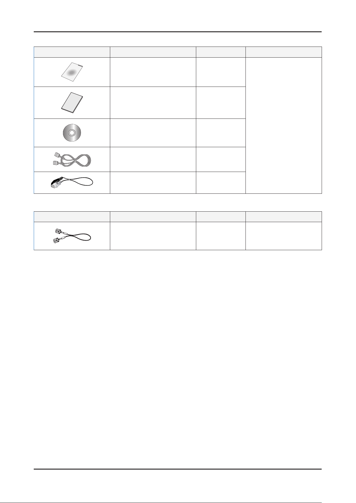
2-3. Accessories
Product Description Ccde. No Remark
2. Product specications
Quick Setup Guide BH68-00376L
Warranty Card
(Not available in all locations)
User’s Guide,
Monitor Driver
D-Sub(15 Pin) Cable BN39-00244A
Power Cord 3903-000042
2-4. Accessories (Sold separately)
Product Description Ccde. No Remark
DVI-D Cable BN39-00246F
BH68-00633A
BN59-00585T
Samsung Electronics
Service center
Samsung Electronics
Service center
2-3
Page 11

2. Product specications
Memo
2-4
Page 12
3. Disassembly and Reassemble
3. Disassembly and Reassemble
This section of the service manual describes the disassembly and reassembly procedures for the LS57BPP LCD monitor.
WARNING: This monitor contains electrostatically sensitive devices. Use caution when handling these components.
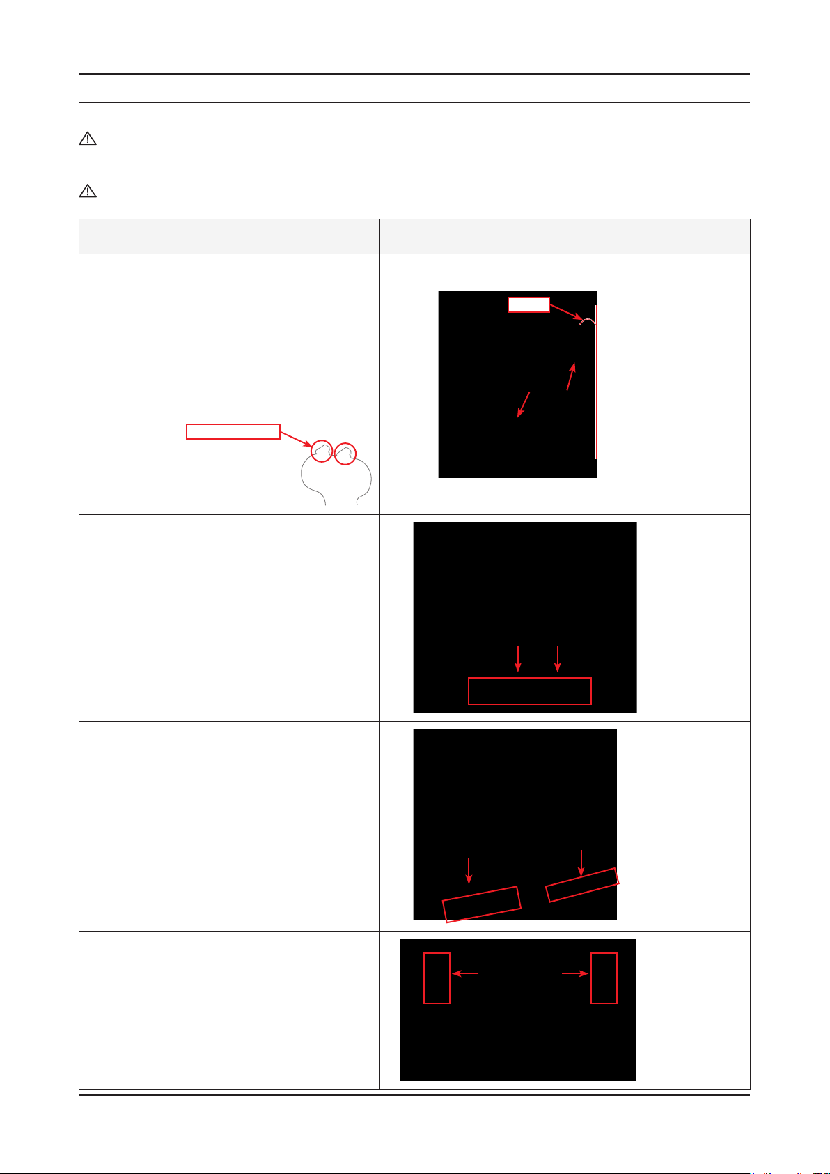
3-1. Disassembly
Cautions: 1. Disconnect the monitor from the power source before disassembly.
2. Follow these directions carefully; never use metal instruments to pry apart the cabinet.
Description Picture Description Screws
1. Placeasoftclothontheoorandplacethe
monitor on it so that the front of the monitor is on
the cloth. Lean the top of the stand backwards
until it is at an angle of 5° to 10° and hold and
push the top of the monitor downwards.
Caution: If you try to forcefully remove the monitor
without leaning the stand backwards, the
connecting pin may break. Be careful.
Fragile: Do not break
5° to 10°
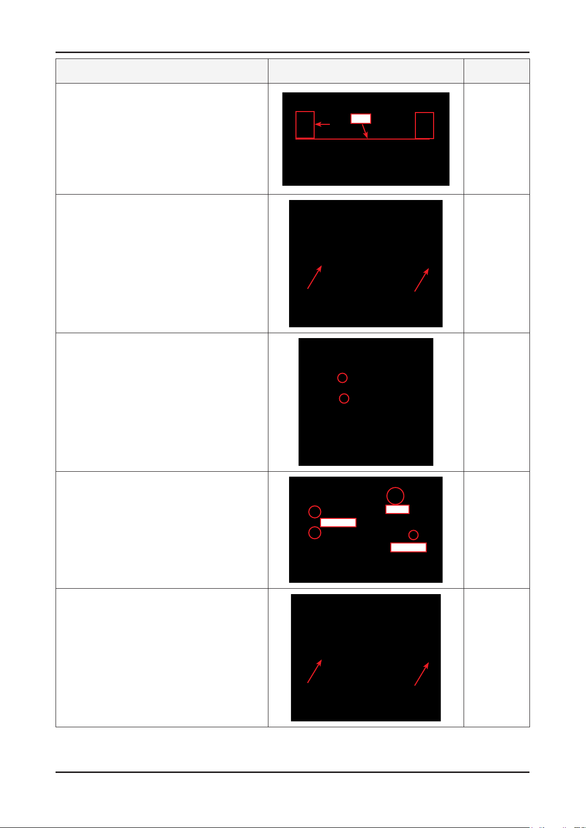
2. Turn the monitor so the front section is facing
upwards. Remove the marked parts from the
frontcover,asshowninthegurebelow.
3. Remove the marked part from the top edge of
thefrontcover,asshowninthegurebelow.
4. Remove the marked parts from both sides of the
frontcover,asshowninthegurebelow.
3-1
Page 13
3-2
3. Disassembly and Reassemble
Description Picture Description Screws
5. Remove the marked part from the front cover, as
showninthegurebelow.
Caution: Do not lift the front cover over position (1),
which may cause damage to it.
6. Turn the monitor so the back of it is facing
upwards. Lift up and remove the back cover.
(A)
7. Use the jig to remove the shield lamp.
(Be careful Shield.)
8. Disconnect cables.
(LVDS, INVERTER and FUNCTION cable)
9. Lift up the LCD panel.
LVDS
INVERTER
FUNCTION
Page 14

Description Picture Description Screws
10. Remove 4 screws.
11. Remove 5 screws and Lift up the Bracket
Support.
3. Disassembly and Reassemble
Bracket Support
12. Lift up the Main PCB and IB Board.
13. Main PCB and IB Board.
Reassembly procedures are in the reverse order of disassembly procedures.※
3-3
Page 15
3-4
3. Disassembly and Reassemble
3-2. Stand
3-2-1. Installing the Stand
A: Monitor
B: Connecting pin
C: Stand
Caution
When lifting up or moving the monitor, do not
lift the monitor upside down while holding only
the stand, as this may cause the monitor to
fall, leading to damage
or personal injury.
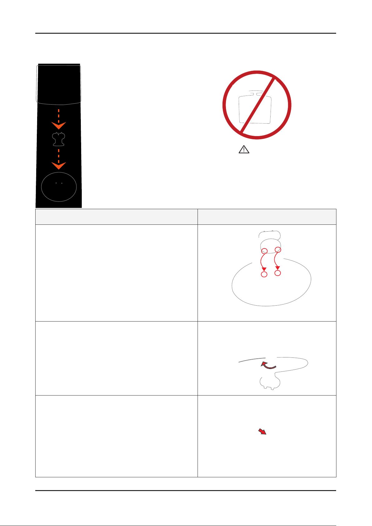
Description Picture Description
1. Insert the connecting pin into the stand.
2. Standthescrewhandlesupandtightenthescrewsrmly
by turning them.
3. Place the screw handles back down.
Page 16
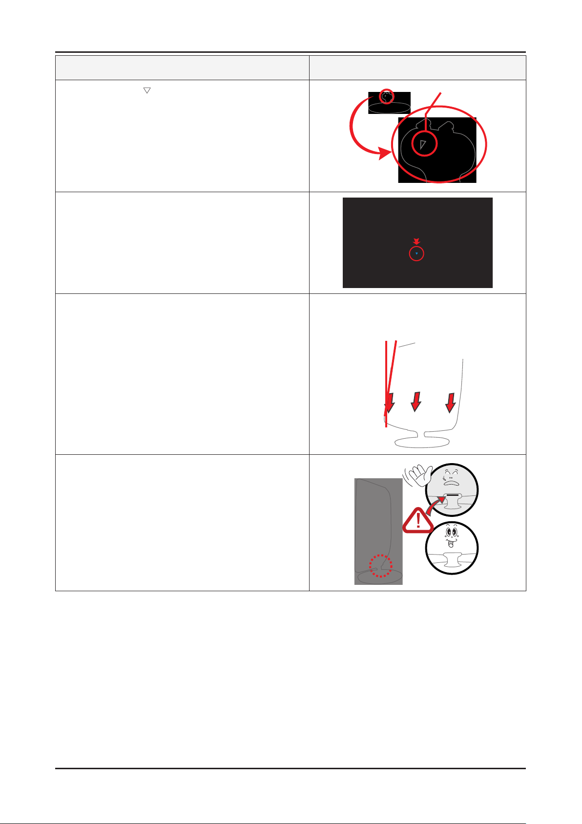
Description Picture Description
4. Turn the stand so mark on the connecting pin is facing
the front.
5. Check the connecting part between the monitor and the
stand.
6. Tilt the monitor upwards at an angle of 5 ° to 10° so that the
base is closer to you than the top. Then hold the monitor on
the stand by its top parts and push them downwards.
3. Disassembly and Reassemble
(You can assemble it more easily by pushing it down while
wriggling it a little to the left and right.)
7. When the monitor is assembled correctly, the straight
groove line at the back of the connecting pin will not be
visible when the monitor is erected at 90°.
3-5
Page 17
3. Disassembly and Reassemble
3-2-2. Removing the Stand
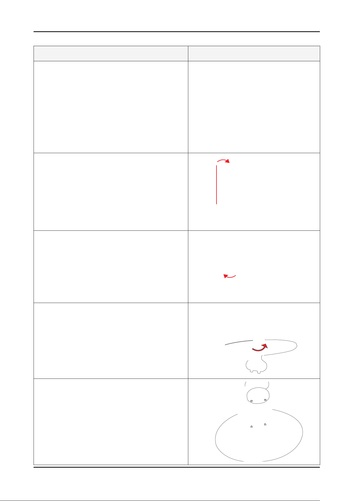
Description Picture Description
1. Place a soft cloth or cushion on the table and place the
monitor with the front facing downwards.
2. Hold the monitor and lean the stand upwards.
3. Hold the monitor, and then twist the stand strongly to the
left and pull it out.
4. Stand the screw handles up and unfasten the screws by
turning them.
5. Remove the connecting pin from the stand.
3-6
Page 18

4. Troubleshooting
4-1. Troubleshooting
1.
Before troubleshooting, setup the PC ‘s display as below.
• Resolution: 1280 x 1024
• H-frequency: 65 kHz
• V-frequency: 60 Hz
2.
If no picture appears, make sure the power cord is correctly connected.
3.
Check the following circuits.
• No raster appears: Function PBA, Main PBA, I/P PBA
• 5V develop but no screen: Main PBA
• 5V does not develop: I/P PBA
4.
If you select Brightness adjust menu and push the “
returns to factory reset.
(Enter/Source)” button for 5 seconds, the monitor automatically
4. Troubleshooting
4-1
Page 19
4. Troubleshooting
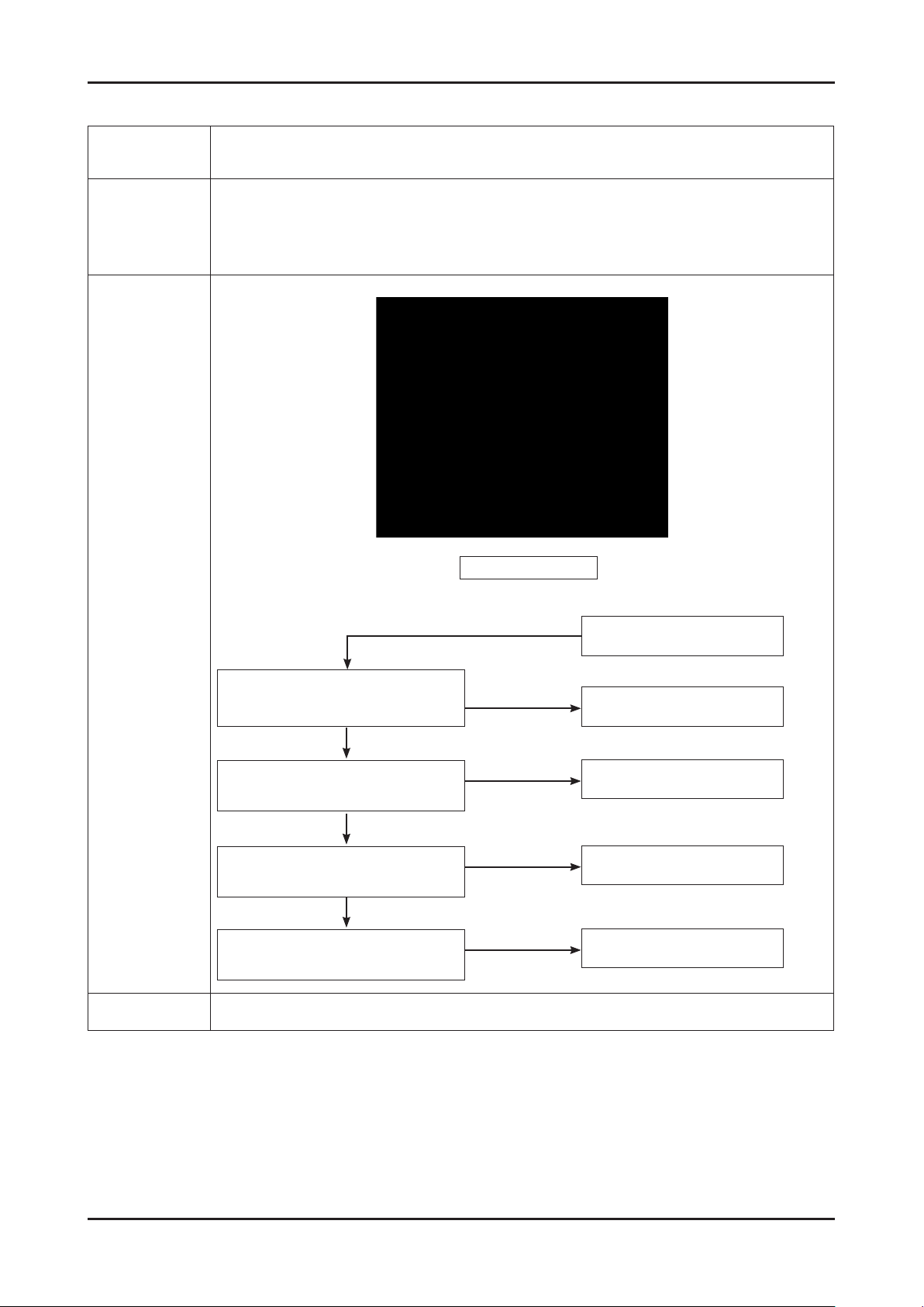
4-2. No Power
Symptom
Major
checkpoints
-
-
-
-
When turning on the Power button after connecting the power, the LED at the front of the
monitor does not operate.
Check the IP board power fuse and the IP board output power.
Check the connections for the IP board and the Main board inside the monitor.
Check the Main board power part and check also whether there is any abnormal output at other
output terminals.
Main Board Front
Diagnostics
When Pin 4 of CN600 is 0V,
Does proper DC 14V appear at pin 5 of
CN600?
Yes
When Pin 1 of IC 702 is DC 14V,
Does proper DC5V appear at pin1 of
IC601
Yes
When pin 1 of IC 601 is DC 5V,
Proper DC 3.3V appear at pin 3 of IC
601
Yes
When pin 3 of IC 602 is DC 5V,
Proper DC 1.8V appear at pin 2 of IC
602
Caution Make sure to disconnect the power before working on the IP board.
Yes
No
No
No
No
Check function assy.
Replace IP board.
Check IC 701 and related
circuit.
Check IC 601 and related
circuit.
Check IC 602 and related
circuit.
4-2
Page 20

4-3. No Video (Analog)
Symptom -Though the LED power turns on, the screen is blank when connecting the VGA cable.
4. Troubleshooting
Major
checkpoints
- Check the D-sub cable connections.
- Check whether the LVDS cable is connected correctly to the panel.
- Check whether the lamp connector of the panel is connected correctly to the IP board.
Main Board Front
Check signal cable connection
and power.
Yes
Diagnostics
Caution Make sure to disconnect the power before working on the IP board.
1
Is there Hsync, Vsync waveform at Pin
3
2
X1 oscillate proprely?
Yes
Is there R,G,B input at
R111,R114 and R118?
Yes
32,33 of IC200?
Yes
Does the output signal appear
at Pin 17~20, 22~27 of CN400?
Yes
There are DC 5V at Pin 1,
2 and 3 of CN400?
Yes
Replace LCD Panel.
No
No
No
No
No
Replace or check related
circuit.
Check input part.
Check IC200 and related
circuit.
Check CN400 and related
circuit.
Check PANEL_EN SIGNAL
at R223 is High(On:High) and
BL_EN signal at R601(ON:
Low) is Low
4-3
Page 21

4. Troubleshooting
4-3-1. Circuit diagrams and waveforms (Analog) when no screen is displayed
on the monitor
1
3
2
4-4
Page 22

4-4. No Video (DVI)
Symptom - The LED power turns on but the screen is blank when the DVI cable is connected.
4. Troubleshooting
Major
checkpoints
Diagnostics
- Check the DVI cable connections.
- Check whether the LVDS cable is connected correctly to the panel.
- Check whether the lamp connector of the panel is connected correctly to the IP board.
Main Board Front
Check signal cable connection
and power.
Yes
1
4
5
6
Caution Make sure to disconnect the power before working on the IP board.
X1 oscillate properly?
Yes
Is there R, G, B input at
R100,R101,R102,R106
and R108?
Yes
Does the output signal appear
at Pin 17~20, 22~27 of CN400?
Yes
There are DC 5V at Pin 1,
2 and 3 of CN400?
Yes
Replace LCD Panel.
No
No
No
No
Check the PANEL_EN signal
at R222 and BL_EN signal at
Replace or check related
circuit.
Check input part.
Check IC400 and related
circuit.
R603.
4-5
Page 23

4. Troubleshooting
4-4-1. Circuit diagrams and waveforms (DVI) when no screen is displayed on
the monitor
1 4
5 6
4-6
Page 24

4-5. Faults and Corrective Actions
Fault Photo Symptoms and Corrective Actions Remarks
Symptoms: DVI signals are not recognized.
Causes: This fault occurs when the PC does not
recognize the mode information because
the DVI DDC has not been input to the
monitor.
Corrective Actions: Input the DVI DDC to the monitor.
* Refer to the Training Manual for
information on inputting the DVI
DDC.
4. Troubleshooting
Symptoms: When the monitor is turned on, only a
full white pattern is displayed continually
regardless of the signals.
Causes:
Corrective Actions: Replace or reconnect the LVDS
This fault occurs when only the lamp
power is supplied and no video signals are
input to the panel due to a fault or incorrect
connections of the LVDS cable.
cable correctly so that video
signals can be supplied to the
panel.
* A
full white pattern is a feature of the
TN panel and is displayed when no
video signals are supplied.
4-7
Page 25

4. Troubleshooting
4-6. Adjustment
4-6-1. Service Adjustment Conditions
Precautions before starting Service Adjustments
1.
1) Check whether the adjustment devices are working correctly.
2) Ensure a sufcient work space for disassembling the monitor.
3) Prepare a soft support for disassembling the monitor.
Entering Service Mode
2.
Entering: Menu
Exiting: Power OFF Power ON
3.
Basic Service Items to perform after Replacing a Board
1) Check the state of the PC color adjustment.
2) Enter the DDC data. (Enter both analog and digital data.)
3) Check whether the MCU code that corresponds to the model has been entered.
4) After completing your work in service mode, reset the monitor and switch it off.
4.
How to execute DDC
1) Enter the DDC EDID data when the AD board is replaced.
Download the DDC input program and the DDC le that corresponds to the model from the Quality Department of
2)
Samsung and install it using a jig as shown in the gure below, and then enter the data.
Brightness 0 Contrast 0
Parallel
Connector
(25P Cable)
Hold down the Enter button for ve seconds
MTI-2031
DDC
Connect Monitor
(Signal Cable)
4-8
Page 26

4-6-2. Service Function Spec.
Service Mode (Entering)
1. Set both the brightness and contrast to 0.
2. Hold down the <Button>(Enter, Source) button for ve (5) seconds.
3. The SVC Function OSD will appear.
- To exit the SVC Function OSD, you have to turn off the power.
Panel Information
MCU Version
Checksum
The SVC Function OSD consists of a 29 (width) X 12 (height) grid.
The SVC Function OSD shows the information, software version and Micom checksum.
4. Troubleshooting
Service Mode (Moving around)
1. Each time the + button is pressed, menu is selected. Then, you can adjust sub menu with - button
4-9
Page 27

4. Troubleshooting
Service Mode (Replacing the Panel)
- When replacing the panel
After replacing the panel, select the Panel item and then hold down the Menu button for ve (5) seconds.
The Ch. No. of the panel will increase by one (1) and the time information will change to 0.
Service Mode (Hot plug Menu)
- HDCP Hotplug : used when HDCP Video contents are not displayed. In case that monitor is connected to some bad
device which does not comply with standard.
- HotPlug Time : If Hotplug is turn on, when monitor power off/on or changing to the DVI, hotplug pin goes to the low. This
function controls this time duration.
Though Hotplug is turn on monitor can’t displayed, adjust this time duration
- Default is 9(means 0.9 sec), can control 5 to 50.
4-10
Page 28

How to execute DDC
1
4. Troubleshooting
2
3
4
5
1) Click the Open icon
2) Select Two EDID
3) Select a DDC le.
4) Select week
5) Click Next (OK).
6
6) Enter the serial number and press the Enter key.
After entering the analog data, repeat the procedure above 2 to 5 times to enter digital data.
※
4-11
Page 29

4. Troubleshooting
How to Execute MCU Code
1
1) Options Checking.
-. Manufacture : MSTAR
-. Device Type:TSUM16_ROM128K_ext_ash
-. Communication Port: DSUB15 (Analog)
-. External Memory: PMC25LV010E
2
2) After click the ‘LoadFile’ button , choose MCU code.
4-12
Page 30

4. Troubleshooting
3
3) ‘Auto Program’ button choice.
4) After the Program and Verify completed, execute hard power off/on.
4-13
Page 31

4. Troubleshooting
Memo
4-14
Page 32

5. Exploded View and Parts List
T0003
M0215
M0174
T0514 M0006
M0013
M0013
5-1. Exploded View
5. Exploded View and Parts List
5-1
Page 33
5-2
5. Exploded View and Parts List
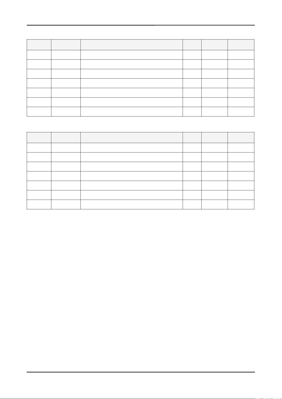
5-1-2. LS20PEBSFV/EDC Parts List
Location Code.No Item & Specication Q’ty SA/SNA Remark
T0003 BN96-05532A ASSY COVER P-FRONT;LS20PEW,ABS HB,BK26,H 1 S.A
M0215 BN07-00374A LCD-PANEL;CLAA201WA04,Doppler,6bit Hi-FR 1 S.A
M0174 BN44-00127R IP BOARD;PWI2004SP(A),PEBBLE 20”,3.2~4.2 1 S.A
M0014 BN94-01340L ASSY PCB MAIN-PTZ,W/W;LS20PEBSF* 1 S.N.A
M0006 BN96-05533A ASSY SHIELD P-COVER;LS20PEW,SECC,T0.8 1 S.N.A
M0013 BN96-05534A ASSY COVER P-REAR;LS20PEW,ABS HB,BK26,H/ 1 S.A
M0013 BN96-04150D ASSY STAND P-BAR;PEBBLE17,ABS HB,BK26,SF 1 S.A
5-1-3. LS22PEBSFV/EDC Parts List
Location Code.No Item & Specication Q’ty SA/SNA Remark
T0003 BN96-05536A ASSY COVER P-FRONT;LS22PEW,ABS HB,BK26,H 1 S.A
M0215 BN07-00427A LCD-PANEL;M220Z1-L03,Mendel,6bit Hi-FRC, 1 S.A
M0174 BN44-00127Q IP BOARD;IP-45130B,PEBBLE 22”,3.0 ~5.0mA 1 S.A
M0014 BN94-01340Z ASSY PCB MAIN-CTZ,W/W;LS22PEBSF 1 S.N.A
M0006 BN96-05533A ASSY SHIELD P-COVER;LS20PEW,SECC,T0.8 1 S.N.A
M0013 BN96-05535A ASSY COVER P-REAR;LS22PEW,ABS HB,BK26,H/ 1 S.A
M0013 BN96-04150D ASSY STAND P-BAR;PEBBLE17,ABS HB,BK26,SF 1 S.A
Page 34

5. Exploded View and Parts List
5-2. LS20PEBSFV/EDC Parts List
Level Location Code.No Item & Specication Q’ty SA/SNA Remark
LS20PEBSFV/EDC 2032BW,WSJ1/S20P0-LPE,20,LCD-MO,NETHERLA
0.1 M0001 BN90-01313A ASSY COVER FRONT;LS20PE 1 S.N.A
..2 T0003 BN96-05532A ASSY COVER P-FRONT;LS20PEW,ABS HB,BK26,H 1 S.A
...3 M0081 6003-000282 SCREW-TAPTITE;BH,+,-,B,M3,L8,ZPC(BLK),SW 2 S.A
...3 BN61-02829A GUIDE-PANEL;PEBBLE,SECC,0.5,LS19PEB 1 S.N.A
...3 CCM1 BN63-02183D COVER-SHEET;Rhcm,PE Vinyl,T0.05,680mm,20 0.5 S.N.A
...3 M0112 BN63-03528A COVER-FRONT;LS20PEW,ABS,HB,BK26,H/GLOSSY 1 S.N.A
...3 M0130 BN67-00193A LENS LED;PEBBLE,ABS HB,CLR 1 S.N.A
...3 M0145 BN96-04363B ASSY BOARD P-FUNCTION;Pebble_2032_2232,S 1 S.A
...3 T0022 BN64-00534B KNOB CONTROL;PEBBLE,ABS,HB,BK26 1 S.N.A
...3 T0023 BN64-00597B KNOB POWER;PEBBLE,black highglossy 1 S.N.A
0.1 M0002 BN90-01314A ASSY COVER REAR;LS20PE 1 S.N.A
..2 M0013 BN96-05534A ASSY COVER P-REAR;LS20PEW,ABS HB,BK26,H/ 1 S.A
...3 M0081 6003-001003 SCREW-TAPTITE;BH,+,B,M4,L12,ZPC(BLK),SWR 4 S.N.A
...3 T0060 BN61-02830A SPRING ETC;PEBBLE,SK5,1.0,LS19PEB,HRC 45 1 S.N.A
...3 M0006 BN63-03530A COVER-REAR;LS20PEW,ABS,HB,BK26,H/GLOSSY 1 S.N.A
...3 M0014 BN63-02880B COVER-STAND BAR;PEBBLE,ABS HB,T2.6,BK26, 1 S.N.A
...3 BN63-02883B COVER-HINGE;PEBBLE,ABS HB,T2.6,BK26,HF-0 1 S.N.A
...3 T0102 BN73-00132B RUBBER-CAP;PEBBLE,ELASTOMER,BK07,HB 1 S.N.A
...3 CCM1 BN63-02183D COVER-SHEET;Rhcm,PE Vinyl,T0.05,680mm,20 0.5 S.N.A
0.1 M0135 BN91-01517B ASSY LCD-PTZ;LS20MEW* 1 S.N.A
..2 M0215 BN07-00374A LCD-PANEL;CLAA201WA04,Doppler,6bit Hi-FR 1 S.A
0.1 M0017 BN91-01630A ASSY CHASSIS-PTZ,W/W;LS20PEBSF* 1 S.A
..2 M0081 6003-000282 SCREW-TAPTITE;BH,+,-,B,M3,L8,ZPC(BLK),SW 1 S.A
..2 M0081 6003-000282 SCREW-TAPTITE;BH,+,-,B,M3,L8,ZPC(BLK),SW 3 S.A
..2 M0081 6003-001439 SCREW-TAPTITE;BH,+,-,S,M4,L8,ZPC(WHT),SW 1 S.N.A
..2 T0562 6046-001013 STAND OFF;M3,L5,Ni PLT,SUM24L,#4-40 4 S.N.A
..2 M0174 BN44-00127R IP BOARD;PWI2004SP(A),PEBBLE 20”,3.2~4.2 1 S.A
..2 M0014 BN94-01340L ASSY PCB MAIN-PTZ,W/W;LS20PEBSF* 1 S.N.A
...3 T0245 0202-001492 SOLDER-WIRE FLUX;HSE-02 LFM48 SR-34 S,-, 0.003 S.N.A
...3 CN102 3701-001173 CONNECTOR-DVI;24P,3R,FEMALE,ANGLE,AUF 1 S.A
...3 CN101 3701-001219 CONNECTOR-DSUB;15P,3R,FEMALE,ANGLE,AUF 1 S.A
...3 HDCP BN97-00707A ASSY HDCP;BN46-00018A,BR20/21BS_CS,MSTAR 1 S.N.A
....4 BN46-00018A KEY CODE-CERTIFICATE;(HDCP KEY)PPM42M5S, 1 S.N.A
...3 T0174 BN97-01626L ASSY SMD;LS20PEBSF* 1 S.N.A
....4 SUB05 0202-001477 SOLDER-CREAM;LST309-M,-,D20~45㎛,96.5Sn/ 0.799 S.N.A
....4 D100 0401-001056 DIODE-SWITCHING;MMBD4148SE,100V,200mA,SO 1 S.A
....4 D101 0401-001056 DIODE-SWITCHING;MMBD4148SE,100V,200mA,SO 1 S.A
....4 D102 0401-001056 DIODE-SWITCHING;MMBD4148SE,100V,200mA,SO 1 S.A
....4 D103 0401-001056 DIODE-SWITCHING;MMBD4148SE,100V,200mA,SO 1 S.A
....4 D104 0401-001056 DIODE-SWITCHING;MMBD4148SE,100V,200mA,SO 1 S.A
....4 D105 0401-001056 DIODE-SWITCHING;MMBD4148SE,100V,200mA,SO 1 S.A
....4 D106 0401-001056 DIODE-SWITCHING;MMBD4148SE,100V,200mA,SO 1 S.A
....4 D107 0401-001056 DIODE-SWITCHING;MMBD4148SE,100V,200mA,SO 1 S.A
5-3
Page 35

5-4
5. Exploded View and Parts List
Level Location Code.No Item & Specication Q’ty SA/SNA Remark
....4 D108 0401-001056 DIODE-SWITCHING;MMBD4148SE,100V,200mA,SO 1 S.A
....4 D109 0401-001056 DIODE-SWITCHING;MMBD4148SE,100V,200mA,SO 1 S.A
....4 D110 0401-001056 DIODE-SWITCHING;MMBD4148SE,100V,200mA,SO 1 S.A
....4 D0254 0402-000553 DIODE-SCHOTTKY;SS24/B240,40V,2000mA,DO-2 1 S.A
....4 D600 0402-001614 DIODE-RECTIFIER;S1G,400V,1A,DO-214AC,TP 1 S.A
....4 D603 0402-001614 DIODE-RECTIFIER;S1G,400V,1A,DO-214AC,TP 1 S.A
....4 D111 0403-000258 DIODE-ZENER;BZX84C5V6,5.2-6V,225mW,SOT-2 1 S.A
....4 D112 0403-000258 DIODE-ZENER;BZX84C5V6,5.2-6V,225mW,SOT-2 1 S.A
....4 ZD100 0403-001411 DIODE-ZENER;-,5.49-5.73V,200mW,SOD-323,T 1 S.A
....4 ZD101 0403-001411 DIODE-ZENER;-,5.49-5.73V,200mW,SOD-323,T 1 S.A
....4 ZD102 0403-001411 DIODE-ZENER;-,5.49-5.73V,200mW,SOD-323,T 1 S.A
....4 D0254 0404-001020 DIODE-SCHOTTKY;BAT54C,30V,200mA,SOT-23,T 1 S.A
....4 D0254 0404-001020 DIODE-SCHOTTKY;BAT54C,30V,200mA,SOT-23,T 1 S.A
....4 ZD200 0406-001061 DIODE-TVS;MMQA5V6T3,5.32/5.6/5.88V,24W,S 1 S.A
....4 ZD201 0406-001061 DIODE-TVS;MMQA5V6T3,5.32/5.6/5.88V,24W,S 1 S.A
....4 ZD202 0406-001061 DIODE-TVS;MMQA5V6T3,5.32/5.6/5.88V,24W,S 1 S.A
....4 Q201 0501-000342 TR-SMALL SIGNAL;KSC1623-Y,NPN,200mW,SOT- 1 S.A
....4 Q203 0501-000342 TR-SMALL SIGNAL;KSC1623-Y,NPN,200mW,SOT- 1 S.A
....4 Q204 0501-000342 TR-SMALL SIGNAL;KSC1623-Y,NPN,200mW,SOT- 1 S.A
....4 Q601 0501-000342 TR-SMALL SIGNAL;KSC1623-Y,NPN,200mW,SOT- 1 S.A
....4 Q401 0501-002080 TR-SMALL SIGNAL;2SC2412K,NPN,200mW,SC-59 1 S.A
....4 Q402 0501-002080 TR-SMALL SIGNAL;2SC2412K,NPN,200mW,SC-59 1 S.A
....4 U291 0501-002080 TR-SMALL SIGNAL;2SC2412K,NPN,200mW,SC-59 1 S.A
....4 Q409 0505-001165 FET-SILICON;SI3443BDV,P,-20V,+-4.4A,65mo 1 S.A
....4 IC112 1103-000129 IC-EEPROM;24C02,2Kbit,256x8Bit,SOP,8P,5x 1 S.A
....4 IC112 1103-001023 IC-EEPROM;24C08,8Kbit,1Kx8Bit,SOP,8P,5x4 1 S.A
....4 IC115 1107-001614 IC-FLASH MEMORY;MX25L1005,1Mbit,1Mx1Bit, 1 S.N.A
....4 IC603 1202-000164 IC-VOLTAGE COMP.;393,SOP,8P,150MIL,DUAL, 1 S.A
....4 IC204 1203-001824 IC-VOL. DETECTOR;7042,SOT-89,3P,-,PLASTI 1 S.A
....4 IC702 1203-002843 IC-DC/DC CONVERTER;AP1501-50K5A,TO-263-5 1 S.A
....4 T0087 1203-003695 IC-POSI.FIXED REG.;NCP1117ST33T3G,SOT-22 1 S.A
....4 T0087 1203-003696 IC-POSI.FIXED REG.;NCP1117DT18T5G,DPAK,3 1 S.A
....4 R608 2007-000052 R-CHIP;10Kohm,1%,1/10W,TP,1608 1 S.A
....4 R245 2007-000070 R-CHIP;0ohm,5%,1/10W,TP,1608 1 S.A
....4 R259 2007-000070 R-CHIP;0ohm,5%,1/10W,TP,1608 1 S.A
....4 R274 2007-000070 R-CHIP;0ohm,5%,1/10W,TP,1608 1 S.A
....4 R275 2007-000070 R-CHIP;0ohm,5%,1/10W,TP,1608 1 S.A
....4 R276 2007-000070 R-CHIP;0ohm,5%,1/10W,TP,1608 1 S.A
....4 R277 2007-000070 R-CHIP;0ohm,5%,1/10W,TP,1608 1 S.A
....4 R100 2007-000071 R-CHIP;22ohm,5%,1/10W,TP,1608 1 S.A
....4 R101 2007-000071 R-CHIP;22ohm,5%,1/10W,TP,1608 1 S.A
....4 R102 2007-000071 R-CHIP;22ohm,5%,1/10W,TP,1608 1 S.A
....4 R103 2007-000071 R-CHIP;22ohm,5%,1/10W,TP,1608 1 S.A
....4 R104 2007-000071 R-CHIP;22ohm,5%,1/10W,TP,1608 1 S.A
....4 R105 2007-000071 R-CHIP;22ohm,5%,1/10W,TP,1608 1 S.A
....4 R106 2007-000071 R-CHIP;22ohm,5%,1/10W,TP,1608 1 S.A
....4 R107 2007-000071 R-CHIP;22ohm,5%,1/10W,TP,1608 1 S.A
....4 R204 2007-000071 R-CHIP;22ohm,5%,1/10W,TP,1608 1 S.A
....4 R205 2007-000071 R-CHIP;22ohm,5%,1/10W,TP,1608 1 S.A
Page 36

5. Exploded View and Parts List
Level Location Code.No Item & Specication Q’ty SA/SNA Remark
....4 R111 2007-000074 R-CHIP;100ohm,5%,1/10W,TP,1608 1 S.A
....4 R113 2007-000074 R-CHIP;100ohm,5%,1/10W,TP,1608 1 S.A
....4 R114 2007-000074 R-CHIP;100ohm,5%,1/10W,TP,1608 1 S.A
....4 R117 2007-000074 R-CHIP;100ohm,5%,1/10W,TP,1608 1 S.A
....4 R118 2007-000074 R-CHIP;100ohm,5%,1/10W,TP,1608 1 S.A
....4 R120 2007-000074 R-CHIP;100ohm,5%,1/10W,TP,1608 1 S.A
....4 R132 2007-000074 R-CHIP;100ohm,5%,1/10W,TP,1608 1 S.A
....4 R202 2007-000074 R-CHIP;100ohm,5%,1/10W,TP,1608 1 S.A
....4 R203 2007-000074 R-CHIP;100ohm,5%,1/10W,TP,1608 1 S.A
....4 R206 2007-000074 R-CHIP;100ohm,5%,1/10W,TP,1608 1 S.A
....4 R207 2007-000074 R-CHIP;100ohm,5%,1/10W,TP,1608 1 S.A
....4 R212 2007-000074 R-CHIP;100ohm,5%,1/10W,TP,1608 1 S.A
....4 R213 2007-000074 R-CHIP;100ohm,5%,1/10W,TP,1608 1 S.A
....4 R216 2007-000074 R-CHIP;100ohm,5%,1/10W,TP,1608 1 S.A
....4 R250 2007-000074 R-CHIP;100ohm,5%,1/10W,TP,1608 1 S.A
....4 R251 2007-000074 R-CHIP;100ohm,5%,1/10W,TP,1608 1 S.A
....4 R252 2007-000074 R-CHIP;100ohm,5%,1/10W,TP,1608 1 S.A
....4 R255 2007-000074 R-CHIP;100ohm,5%,1/10W,TP,1608 1 S.A
....4 R401 2007-000074 R-CHIP;100ohm,5%,1/10W,TP,1608 1 S.A
....4 R108 2007-000080 R-CHIP;2Kohm,5%,1/10W,TP,1608 1 S.A
....4 R123 2007-000080 R-CHIP;2Kohm,5%,1/10W,TP,1608 1 S.A
....4 R270 2007-000080 R-CHIP;2Kohm,5%,1/10W,TP,1608 1 S.A
....4 R208 2007-000082 R-CHIP;3.3Kohm,5%,1/10W,TP,1608 1 S.A
....4 R209 2007-000082 R-CHIP;3.3Kohm,5%,1/10W,TP,1608 1 S.A
....4 R218 2007-000083 R-CHIP;3Kohm,5%,1/10W,TP,1608 1 S.A
....4 R229 2007-000083 R-CHIP;3Kohm,5%,1/10W,TP,1608 1 S.A
....4 R219 2007-000084 R-CHIP;4.7Kohm,5%,1/10W,TP,1608 1 S.A
....4 R220 2007-000084 R-CHIP;4.7Kohm,5%,1/10W,TP,1608 1 S.A
....4 R223 2007-000084 R-CHIP;4.7Kohm,5%,1/10W,TP,1608 1 S.A
....4 R230 2007-000084 R-CHIP;4.7Kohm,5%,1/10W,TP,1608 1 S.A
....4 R234 2007-000084 R-CHIP;4.7Kohm,5%,1/10W,TP,1608 1 S.A
....4 R729 2007-000084 R-CHIP;4.7Kohm,5%,1/10W,TP,1608 1 S.A
....4 R600 2007-000088 R-CHIP;7.5Kohm,5%,1/10W,TP,1608 1 S.A
....4 R109 2007-000090 R-CHIP;10Kohm,5%,1/10W,TP,1608 1 S.A
....4 R125 2007-000090 R-CHIP;10Kohm,5%,1/10W,TP,1608 1 S.A
....4 R126 2007-000090 R-CHIP;10Kohm,5%,1/10W,TP,1608 1 S.A
....4 R130 2007-000090 R-CHIP;10Kohm,5%,1/10W,TP,1608 1 S.A
....4 R131 2007-000090 R-CHIP;10Kohm,5%,1/10W,TP,1608 1 S.A
....4 R200 2007-000090 R-CHIP;10Kohm,5%,1/10W,TP,1608 1 S.A
....4 R201 2007-000090 R-CHIP;10Kohm,5%,1/10W,TP,1608 1 S.A
....4 R210 2007-000090 R-CHIP;10Kohm,5%,1/10W,TP,1608 1 S.A
....4 R211 2007-000090 R-CHIP;10Kohm,5%,1/10W,TP,1608 1 S.A
....4 R214 2007-000090 R-CHIP;10Kohm,5%,1/10W,TP,1608 1 S.A
....4 R215 2007-000090 R-CHIP;10Kohm,5%,1/10W,TP,1608 1 S.A
....4 R217 2007-000090 R-CHIP;10Kohm,5%,1/10W,TP,1608 1 S.A
....4 R239 2007-000090 R-CHIP;10Kohm,5%,1/10W,TP,1608 1 S.A
....4 R253 2007-000090 R-CHIP;10Kohm,5%,1/10W,TP,1608 1 S.A
....4 R254 2007-000090 R-CHIP;10Kohm,5%,1/10W,TP,1608 1 S.A
....4 R271 2007-000090 R-CHIP;10Kohm,5%,1/10W,TP,1608 1 S.A
5-5
Page 37

5-6
5. Exploded View and Parts List
Level Location Code.No Item & Specication Q’ty SA/SNA Remark
....4 R400 2007-000090 R-CHIP;10Kohm,5%,1/10W,TP,1608 1 S.A
....4 R404 2007-000090 R-CHIP;10Kohm,5%,1/10W,TP,1608 1 S.A
....4 R405 2007-000090 R-CHIP;10Kohm,5%,1/10W,TP,1608 1 S.A
....4 R601 2007-000090 R-CHIP;10Kohm,5%,1/10W,TP,1608 1 S.A
....4 R602 2007-000090 R-CHIP;10Kohm,5%,1/10W,TP,1608 1 S.A
....4 R612 2007-000090 R-CHIP;10Kohm,5%,1/10W,TP,1608 1 S.A
....4 R610 2007-000091 R-CHIP;12Kohm,5%,1/10W,TP,1608 1 S.A
....4 R402 2007-000102 R-CHIP;100Kohm,5%,1/10W,TP,1608 1 S.A
....4 R605 2007-000134 R-CHIP;33Kohm,5%,1/10W,TP,1608 1 S.A
....4 R232 2007-000309 R-CHIP;10ohm,5%,1/10W,TP,1608 1 S.A
....4 R273 2007-000309 R-CHIP;10ohm,5%,1/10W,TP,1608 1 S.A
....4 R116 2007-000821 R-CHIP;390ohm,1%,1/10W,TP,1608 1 S.A
....4 R235 2007-000821 R-CHIP;390ohm,1%,1/10W,TP,1608 1 S.A
....4 R110 2007-001002 R-CHIP;510ohm,5%,1/10W,TP,1608 1 S.A
....4 R121 2007-001044 R-CHIP;56ohm,5%,1/10W,TP,1608 1 S.A
....4 R122 2007-001044 R-CHIP;56ohm,5%,1/10W,TP,1608 1 S.A
....4 R112 2007-001164 R-CHIP;75ohm,1%,1/10W,TP,1608 1 S.A
....4 R115 2007-001164 R-CHIP;75ohm,1%,1/10W,TP,1608 1 S.A
....4 R119 2007-001164 R-CHIP;75ohm,1%,1/10W,TP,1608 1 S.A
....4 C215 2203-000189 C-CER,CHIP;100nF,+80-20%,25V,Y5V,1608 1 S.A
....4 C223 2203-000189 C-CER,CHIP;100nF,+80-20%,25V,Y5V,1608 1 S.A
....4 C723 2203-000189 C-CER,CHIP;100nF,+80-20%,25V,Y5V,1608 1 S.A
....4 C724 2203-000189 C-CER,CHIP;100nF,+80-20%,25V,Y5V,1608 1 S.A
....4 C201 2203-000236 C-CER,CHIP;0.1nF,5%,50V,C0G,1608 1 S.A
....4 C202 2203-000236 C-CER,CHIP;0.1nF,5%,50V,C0G,1608 1 S.A
....4 C642 2203-000236 C-CER,CHIP;0.1nF,5%,50V,C0G,1608 1 S.A
....4 C109 2203-000257 C-CER,CHIP;10nF,10%,50V,X7R,1608 1 S.A
....4 C216 2203-000257 C-CER,CHIP;10nF,10%,50V,X7R,1608 1 S.A
....4 C217 2203-000257 C-CER,CHIP;10nF,10%,50V,X7R,1608 1 S.A
....4 C218 2203-000257 C-CER,CHIP;10nF,10%,50V,X7R,1608 1 S.A
....4 C116 2203-000384 C-CER,CHIP;0.015nF,5%,50V,C0G,1608 1 S.A
....4 C115 2203-000626 C-CER,CHIP;0.022nF,5%,50V,C0G,1608 1 S.A
....4 C210 2203-000626 C-CER,CHIP;0.022nF,5%,50V,C0G,1608 1 S.A
....4 C211 2203-000626 C-CER,CHIP;0.022nF,5%,50V,C0G,1608 1 S.A
....4 C100 2203-005005 C-CER,CHIP;100nF,10%,16V,X7R,1608 1 S.A
....4 C101 2203-005005 C-CER,CHIP;100nF,10%,16V,X7R,1608 1 S.A
....4 C103 2203-005005 C-CER,CHIP;100nF,10%,16V,X7R,1608 1 S.A
....4 C106 2203-005005 C-CER,CHIP;100nF,10%,16V,X7R,1608 1 S.A
....4 C107 2203-005005 C-CER,CHIP;100nF,10%,16V,X7R,1608 1 S.A
....4 C108 2203-005005 C-CER,CHIP;100nF,10%,16V,X7R,1608 1 S.A
....4 C110 2203-005005 C-CER,CHIP;100nF,10%,16V,X7R,1608 1 S.A
....4 C111 2203-005005 C-CER,CHIP;100nF,10%,16V,X7R,1608 1 S.A
....4 C112 2203-005005 C-CER,CHIP;100nF,10%,16V,X7R,1608 1 S.A
....4 C117 2203-005005 C-CER,CHIP;100nF,10%,16V,X7R,1608 1 S.A
....4 C118 2203-005005 C-CER,CHIP;100nF,10%,16V,X7R,1608 1 S.A
....4 C119 2203-005005 C-CER,CHIP;100nF,10%,16V,X7R,1608 1 S.A
....4 C120 2203-005005 C-CER,CHIP;100nF,10%,16V,X7R,1608 1 S.A
....4 C121 2203-005005 C-CER,CHIP;100nF,10%,16V,X7R,1608 1 S.A
....4 C122 2203-005005 C-CER,CHIP;100nF,10%,16V,X7R,1608 1 S.A
Page 38

5. Exploded View and Parts List
Level Location Code.No Item & Specication Q’ty SA/SNA Remark
....4 C123 2203-005005 C-CER,CHIP;100nF,10%,16V,X7R,1608 1 S.A
....4 C124 2203-005005 C-CER,CHIP;100nF,10%,16V,X7R,1608 1 S.A
....4 C125 2203-005005 C-CER,CHIP;100nF,10%,16V,X7R,1608 1 S.A
....4 C200 2203-005005 C-CER,CHIP;100nF,10%,16V,X7R,1608 1 S.A
....4 C203 2203-005005 C-CER,CHIP;100nF,10%,16V,X7R,1608 1 S.A
....4 C204 2203-005005 C-CER,CHIP;100nF,10%,16V,X7R,1608 1 S.A
....4 C205 2203-005005 C-CER,CHIP;100nF,10%,16V,X7R,1608 1 S.A
....4 C206 2203-005005 C-CER,CHIP;100nF,10%,16V,X7R,1608 1 S.A
....4 C209 2203-005005 C-CER,CHIP;100nF,10%,16V,X7R,1608 1 S.A
....4 C212 2203-005005 C-CER,CHIP;100nF,10%,16V,X7R,1608 1 S.A
....4 C213 2203-005005 C-CER,CHIP;100nF,10%,16V,X7R,1608 1 S.A
....4 C214 2203-005005 C-CER,CHIP;100nF,10%,16V,X7R,1608 1 S.A
....4 C436 2203-005005 C-CER,CHIP;100nF,10%,16V,X7R,1608 1 S.A
....4 C600 2203-005005 C-CER,CHIP;100nF,10%,16V,X7R,1608 1 S.A
....4 C601 2203-005005 C-CER,CHIP;100nF,10%,16V,X7R,1608 1 S.A
....4 C603 2203-005005 C-CER,CHIP;100nF,10%,16V,X7R,1608 1 S.A
....4 C604 2203-005005 C-CER,CHIP;100nF,10%,16V,X7R,1608 1 S.A
....4 C605 2203-005005 C-CER,CHIP;100nF,10%,16V,X7R,1608 1 S.A
....4 C612 2203-005005 C-CER,CHIP;100nF,10%,16V,X7R,1608 1 S.A
....4 C613 2203-005005 C-CER,CHIP;100nF,10%,16V,X7R,1608 1 S.A
....4 C614 2203-005005 C-CER,CHIP;100nF,10%,16V,X7R,1608 1 S.A
....4 C615 2203-005005 C-CER,CHIP;100nF,10%,16V,X7R,1608 1 S.A
....4 C617 2203-005005 C-CER,CHIP;100nF,10%,16V,X7R,1608 1 S.A
....4 C618 2203-005005 C-CER,CHIP;100nF,10%,16V,X7R,1608 1 S.A
....4 C619 2203-005005 C-CER,CHIP;100nF,10%,16V,X7R,1608 1 S.A
....4 C620 2203-005005 C-CER,CHIP;100nF,10%,16V,X7R,1608 1 S.A
....4 C621 2203-005005 C-CER,CHIP;100nF,10%,16V,X7R,1608 1 S.A
....4 C622 2203-005005 C-CER,CHIP;100nF,10%,16V,X7R,1608 1 S.A
....4 C623 2203-005005 C-CER,CHIP;100nF,10%,16V,X7R,1608 1 S.A
....4 C626 2203-005005 C-CER,CHIP;100nF,10%,16V,X7R,1608 1 S.A
....4 C627 2203-005005 C-CER,CHIP;100nF,10%,16V,X7R,1608 1 S.A
....4 C628 2203-005005 C-CER,CHIP;100nF,10%,16V,X7R,1608 1 S.A
....4 C630 2203-005005 C-CER,CHIP;100nF,10%,16V,X7R,1608 1 S.A
....4 C631 2203-005005 C-CER,CHIP;100nF,10%,16V,X7R,1608 1 S.A
....4 C635 2203-005005 C-CER,CHIP;100nF,10%,16V,X7R,1608 1 S.A
....4 C636 2203-005005 C-CER,CHIP;100nF,10%,16V,X7R,1608 1 S.A
....4 C637 2203-005005 C-CER,CHIP;100nF,10%,16V,X7R,1608 1 S.A
....4 C640 2203-005005 C-CER,CHIP;100nF,10%,16V,X7R,1608 1 S.A
....4 C718 2203-005005 C-CER,CHIP;100nF,10%,16V,X7R,1608 1 S.A
....4 C726 2203-005005 C-CER,CHIP;100nF,10%,16V,X7R,1608 1 S.A
....4 C208 2203-005065 C-CER,CHIP;1000nF,+80-20%,10V,Y5V,1608 1 S.A
....4 C220 2203-005065 C-CER,CHIP;1000nF,+80-20%,10V,Y5V,1608 1 S.A
....4 C222 2203-005065 C-CER,CHIP;1000nF,+80-20%,10V,Y5V,1608 1 S.A
....4 C309 2203-005065 C-CER,CHIP;1000nF,+80-20%,10V,Y5V,1608 1 S.A
....4 C606 2203-005065 C-CER,CHIP;1000nF,+80-20%,10V,Y5V,1608 1 S.A
....4 C610 2203-005065 C-CER,CHIP;1000nF,+80-20%,10V,Y5V,1608 1 S.A
....4 C641 2203-005065 C-CER,CHIP;1000nF,+80-20%,10V,Y5V,1608 1 S.A
....4 C207 2203-005437 C-CER,CHIP;10000nF,+80-20%,10V,Y5V,3216 1 S.A
....4 C221 2203-005437 C-CER,CHIP;10000nF,+80-20%,10V,Y5V,3216 1 S.A
5-7
Page 39

5-8
5. Exploded View and Parts List
Level Location Code.No Item & Specication Q’ty SA/SNA Remark
....4 C602 2203-005437 C-CER,CHIP;10000nF,+80-20%,10V,Y5V,3216 1 S.A
....4 C611 2203-005437 C-CER,CHIP;10000nF,+80-20%,10V,Y5V,3216 1 S.A
....4 C616 2203-005437 C-CER,CHIP;10000nF,+80-20%,10V,Y5V,3216 1 S.A
....4 C624 2203-005437 C-CER,CHIP;10000nF,+80-20%,10V,Y5V,3216 1 S.A
....4 C625 2203-005437 C-CER,CHIP;10000nF,+80-20%,10V,Y5V,3216 1 S.A
....4 C632 2203-005437 C-CER,CHIP;10000nF,+80-20%,10V,Y5V,3216 1 S.A
....4 C633 2203-005437 C-CER,CHIP;10000nF,+80-20%,10V,Y5V,3216 1 S.A
....4 C634 2203-005437 C-CER,CHIP;10000nF,+80-20%,10V,Y5V,3216 1 S.A
....4 C638 2203-005437 C-CER,CHIP;10000nF,+80-20%,10V,Y5V,3216 1 S.A
....4 C722 2402-001081 C-AL,SMD;100uF,20%,25V,WT,TP,8.3x8.3x10 1 S.A
....4 C435 2402-001128 C-AL,SMD;100μF,20%,16V,-,TP,6.3X5.7mm 1 S.A
....4 C629 2402-001128 C-AL,SMD;100μF,20%,16V,-,TP,6.3X5.7mm 1 S.A
....4 C639 2402-001128 C-AL,SMD;100μF,20%,16V,-,TP,6.3X5.7mm 1 S.A
....4 C719 2402-001128 C-AL,SMD;100μF,20%,16V,-,TP,6.3X5.7mm 1 S.A
....4 C725 2402-001128 C-AL,SMD;100μF,20%,16V,-,TP,6.3X5.7mm 1 S.A
....4 X1 2801-003667 CRYSTAL-SMD;14.31818MHz,30ppm,28-AAN,16p 1 S.A
....4 T0568 3301-001407 BEAD-SMD;30ohm,1608,300mA,TP,,,0.4ohm 1 S.N.A
....4 T0568 3301-001407 BEAD-SMD;30ohm,1608,300mA,TP,,,0.4ohm 1 S.N.A
....4 T0568 3301-001569 BEAD-SMD;600ohm,2012,1000mA,TP,520ohm/90 1 S.N.A
....4 T0568 3301-001569 BEAD-SMD;600ohm,2012,1000mA,TP,520ohm/90 1 S.N.A
....4 T0568 3301-001569 BEAD-SMD;600ohm,2012,1000mA,TP,520ohm/90 1 S.N.A
....4 T0568 3301-001569 BEAD-SMD;600ohm,2012,1000mA,TP,520ohm/90 1 S.N.A
....4 T0568 3301-001569 BEAD-SMD;600ohm,2012,1000mA,TP,520ohm/90 1 S.N.A
....4 T0568 3301-001569 BEAD-SMD;600ohm,2012,1000mA,TP,520ohm/90 1 S.N.A
....4 T0568 3301-001569 BEAD-SMD;600ohm,2012,1000mA,TP,520ohm/90 1 S.N.A
....4 T0568 3301-001569 BEAD-SMD;600ohm,2012,1000mA,TP,520ohm/90 1 S.N.A
....4 T0568 3301-001569 BEAD-SMD;600ohm,2012,1000mA,TP,520ohm/90 1 S.N.A
....4 CN330 3711-005503 HEADER-BOARD TO CABLE;BOX,9P,1R,2mm,SMD- 1 S.A
....4 CN330 3711-005509 HEADER-BOARD TO CABLE;BOX,4P,1R,1.25mm,S 1 S.A
....4 L701 BN27-00008A COIL CHOKE-SMD;SMD12*12*8.5,GH15/17PS,22 1 S.A
....4 MICOM BN97-01604W ASSY MICOM-PTZ,W/W;LS20PEBSF* 1 S.N.A
.....5 IC109 1205-003255 IC-LCD CONTROLLER;SE758MRH-LF,PQFP,128P, 1 S.A
....4 CN400 3708-001150 CONNECTOR-FPC/FFC/PIC;30P,1mm,SMD-A,SN,Y 1 S.A
....4 T0077 BN41-00890A PCB MAIN;PEBBLE,CM-3,4,1.0,1.6T,179.6mm 1 S.N.A
....4 T0568 3301-001145 BEAD-SMD;60ohm,4516,TP,70ohm/45MHz,82ohm 1 S.N.A
....4 IC104 0801-002478 IC-CMOS LOGIC;7SZ14,SCHMITT TRIGGER,SOT2 1 S.A
....4 R256 2007-000075 R-CHIP;220ohm,5%,1/10W,TP,1608 1 S.A
....4 R257 2007-000078 R-CHIP;1Kohm,5%,1/10W,TP,1608 1 S.A
....4 R258 2007-000078 R-CHIP;1Kohm,5%,1/10W,TP,1608 1 S.A
..2 M0006 BN96-05533A ASSY SHIELD P-COVER;LS20PEW,SECC,T0.8 1 S.N.A
...3 BN61-02429D STUD-PEM;PNB,M2.8,D7,L20,ZPC(SIL),SUM24L 1 S.N.A
...3 M0107 BN63-03531A SHIELD-COVER;LS20PEW,SECC,T 0.8 1 S.N.A
...3 M0131 BN63-03831A GASKET;PEBBLE,71TS-FK 10-2-110-15,2T,10m 3 S.N.A
..2 M2893 AB39-00119A LEAD CONNECTOR;ORION,UL1007#26,UL/CSA,9 1 S.A
..2 M0596 BN96-05621A ASSY MISC P-FLAT CABLE;Mendel,FLAT CABLE 1 S.A
..2 T0514 BN61-02784A BRACKET-SUPPORT;PEBBLE,SPTE,0.3 1 S.N.A
0.1 M0112 BN91-01638A ASSY SHIELD;LS20PE 1 S.N.A
..2 BN63-03532A SHIELD-LAMP;LS20PEW,SPTE,T 0.3 1 S.N.A
Page 40

5. Exploded View and Parts List
Level Location Code.No Item & Specication Q’ty SA/SNA Remark
0.1 M0113 BN92-02621G ASSY P/MATERIAL;LS20PEJSFV/EDC 1 S.N.A
..2 T0376 6902-000061 BAG AIR;LDPE,T0.2,L1000,W500,TRP,,, 0.004 S.N.A
..2 T0524 6902-000241 BAG PE;NITRON/HDPE,T0.5/T0.012,W600,L600 1 S.N.A
..2 T0376 6902-000379 BAG AIR;LDPE,T0.2,W1000,L1800,TRP,-,-- 0.001 S.N.A
..2 T0524 6902-000389 BAG PE;HDPE/NITRON/HDPE,T0.015/T0.5/T0.0 1 S.N.A
..2 T0003 6902-000604 BAG WRAPPING;LDPE,T0.02,W500,L10000,TRP, 1.11 S.N.A
..2 M0081 6902-000609 BAG ROLL;LDPE,T0.05,W2400,L1000,TRP,-,- 0.02 S.N.A
0.1 M0019 BN92-02653R ASSY LABEL;LS20EJSFV/EDC 1 S.N.A
0.1 M0045 BN92-02720Z ASSY ACCESSORY;LS20PEBSFV/EDC 1 S.N.A
..2 M0114 BN39-00244B CBF SIGNAL;MO15PS,15P/15P,20276-N,1830mm 1 S.A
..2 M0125 BN39-00246F CBF SIGNAL-DVI(D);1703FP,24P/24P,20276-D 1 S.A
..2 BN68-01115C MANUAL FLYER-QSG;COMM,SyncMaster,korean, 1 S.N.A
..2 M0013 BN96-04150D ASSY STAND P-BAR;PEBBLE17,ABS HB,BK26,SF 1 S.A
...3 M0081 6003-000282 SCREW-TAPTITE;BH,+,-,B,M3,L8,ZPC(BLK),SW 2 S.A
...3 T0524 6902-000023 BAG PE;LDPE,T0.08,L120,W150,TRP,,,PE MAR 1 S.N.A
...3 BN61-02783D STAND-BAR;PEBBLE,ABS HB,SL-414WH,BK26,SF 1 S.N.A
...3 BN61-02786A BRACKET-PLATE;PEBBLE,SECC,1.0 1 S.N.A
..2 M0027 BN96-04154B ASSY STAND P-BASE;PEBBLE19,ABS HB,BK26 1 S.A
...3 M0081 6003-000282 SCREW-TAPTITE;BH,+,-,B,M3,L8,ZPC(BLK),SW 4 S.A
...3 T0524 6902-000389 BAG PE;HDPE/NITRON/HDPE,T0.015/T0.5/T0.0 1 S.N.A
...3 CIS4 BN61-01717A HOLDER-STAND;BIZET,NI PLT,CH,+,M4,L11(5) 1 S.A
...3 BN61-02785A BRACKET-STAND BODY;PEBBLE,SECC,0.8 1 S.N.A
...3 CCM1 BN63-02183C COVER-SHEET;Rhcm,PE Vinyl,T0.05,200mm,20 0.3 S.N.A
...3 T0004 BN63-02882B COVER-STAND BASE;PEBBLE,ABS,2.6,HB,BK26 1 S.N.A
...3 T0132 BN73-00077A RUBBER FOOT;MATISSE,BUMPON,Ø13.5,T2.0,6 4 S.N.A
...3 BN68-01115A MANUAL FLYER-QSG;COMM,SyncMaster,korean, 1 S.N.A
..2 M0045 BN96-05553K ASSY ACCESSORY;LS20PEJSFV/EDC 1 S.N.A
...3 T0268 3903-000042 CBF-POWER CORD;DT,EU,FP3/YES,IEC320 C13/ 1 S.A
...3 T0524 6902-000110 BAG PE;LDPE,T0.05,W250,L400,TRP,28,2 1 S.N.A
...3 ACCESSORY BH68-00633A MANUAL FLYER-WARRANTY CARD,03;comm,Samsu 1 S.N.A
...3 ACCESSORY BH68-70448A CARD-01;TFT LCD,SRC,RUSSIA,S/W,120,W210* 1 S.N.A
...3 ACCESSORY BN63-02368A CLOTH;LS07BTT,SUEDE,0.6,160,120 1 S.N.A
...3 ACCESSORY BN68-00907A MANUAL FLYER-01,CARD;COMM,SAMSUNG,18 LAN 1 S.N.A
...3 ACCESSORY BN68-01237A MANUAL FLYER-QSG;COMM,W/W(L12),Mojo 100g 1 S.N.A
...3 M0215 BN96-04304T ASSY MANUAL P-IB+QSG;2032GW,2232GW,2032B 1 S.N.A
....4 QSG BH68-00376L MANUAL FLYER-06,QSG;LCDQUICK SETUP GUIDE 1 S.N.A
....4 IB BN59-00585T S/W DRIVER-00,IB;2032GW,2232GW,2032BW,22 1 S.N.A
0.1 M0003 BN92-02721R ASSY BOX;LS20PEBSFV/EDC 1 S.N.A
..2 M0045 BN69-01921A BOX-MONITOR;LS20PEW,CB,SY-01,A1,W537,D39 1.02 S.N.A
..2 T0081 BN96-02895A ASSY MISC P-HANDLE PACKING;ALL MODEL,BN6 1 S.N.A
...3 M0103 BN66-00007A LEVER-TOP;ALL MODEL,LDPE,WHITE 1 S.N.A
...3 M0102 BN66-00008A LEVER-BOTTOM;ALL MODEL,LDPE,WHITE 1 S.N.A
5-9
Page 41

5-10
5. Exploded View and Parts List
5-3. LS22PEBSFV/EDC Parts List
Level Location Code.No Item & Specication Q’ty SA/SNA Remark
LS22PEBSFV/EDC 2232BW,WSK1/S22P0-LPE,22,LCD-MO,NETHERLA
0.1 M0001 BN90-01323A ASSY COVER FRONT;LS22PE,2232BW 1 S.N.A
..2 T0003 BN96-05536A ASSY COVER P-FRONT;LS22PEW,ABS HB,BK26,H 1 S.A
...3 M0081 6003-000282 SCREW-TAPTITE;BH,+,-,B,M3,L8,ZPC(BLK),SW 2 S.A
...3 BN61-03222A GUIDE-PANEL;LS17PEW,SECC,T 0.5 1 S.N.A
...3 CCM1 BN63-02183D COVER-SHEET;Rhcm,PE Vinyl,T0.05,680mm,20 0.5 S.N.A
...3 M0112 BN63-03529A COVER-FRONT;LS22PEW,ABS,HB,BK26,H/GLOSSY 1 S.N.A
...3 T0022 BN64-00534B KNOB CONTROL;PEBBLE,ABS,HB,BK26 1 S.N.A
...3 T0023 BN64-00597B KNOB POWER;PEBBLE,black highglossy 1 S.N.A
...3 M0130 BN67-00193A LENS LED;PEBBLE,ABS HB,CLR 1 S.N.A
...3 M0145 BN96-04363B ASSY BOARD P-FUNCTION;Pebble_2032_2232,S 1 S.A
0.1 M0002 BN90-01324A ASSY COVER REAR;LS22PE 1 S.N.A
..2 M0013 BN96-05535A ASSY COVER P-REAR;LS22PEW,ABS HB,BK26,H/ 1 S.A
...3 M0081 6003-001003 SCREW-TAPTITE;BH,+,B,M4,L12,ZPC(BLK),SWR 4 S.N.A
...3 T0060 BN61-02830A SPRING ETC;PEBBLE,SK5,1.0,LS19PEB,HRC 45 1 S.N.A
...3 CCM1 BN63-02183D COVER-SHEET;Rhcm,PE Vinyl,T0.05,680mm,20 0.5 S.N.A
...3 M0014 BN63-02880B COVER-STAND BAR;PEBBLE,ABS HB,T2.6,BK26, 1 S.N.A
...3 BN63-02883B COVER-HINGE;PEBBLE,ABS HB,T2.6,BK26,HF-0 1 S.N.A
...3 M0006 BN63-03533A COVER-REAR;LS22PEW,ABS,HB,BK26,H/GLOSSY 1 S.N.A
...3 T0102 BN73-00132B RUBBER-CAP;PEBBLE,ELASTOMER,BK07,HB 1 S.N.A
0.1 M0107 BN91-01517P ASSY LCD-CTZ;LS22PEB* 1 S.N.A
..2 M0215 BN07-00427A LCD-PANEL;M220Z1-L03,Mendel,6bit Hi-FRC, 1 S.A
0.1 M0017 BN91-01630R ASSY CHASSIS-CTZ,W/W;LS22PEBSF/XAA 1 S.A
..2 M0081 6003-000282 SCREW-TAPTITE;BH,+,-,B,M3,L8,ZPC(BLK),SW 1 S.A
..2 M0081 6003-000282 SCREW-TAPTITE;BH,+,-,B,M3,L8,ZPC(BLK),SW 3 S.A
..2 M0081 6003-001439 SCREW-TAPTITE;BH,+,-,S,M4,L8,ZPC(WHT),SW 1 S.N.A
..2 T0562 6046-001013 STAND OFF;M3,L5,Ni PLT,SUM24L,#4-40 4 S.N.A
..2 M0174 BN44-00127Q IP BOARD;IP-45130B,PEBBLE 22”,3.0 ~5.0mA 1 S.A
..2 M0014 BN94-01340Z ASSY PCB MAIN-CTZ,W/W;LS22PEBSF 1 S.N.A
...3 T0245 0202-001492 SOLDER-WIRE FLUX;HSE-02 LFM48 SR-34 S,-, 0.003 S.N.A
...3 CN102 3701-001173 CONNECTOR-DVI;24P,3R,FEMALE,ANGLE,AUF 1 S.A
...3 CN101 3701-001219 CONNECTOR-DSUB;15P,3R,FEMALE,ANGLE,AUF 1 S.A
...3 HDCP BN97-00707A ASSY HDCP;BN46-00018A,BR20/21BS_CS,MSTAR 1 S.N.A
....4 BN46-00018A KEY CODE-CERTIFICATE;(HDCP KEY)PPM42M5S, 1 S.N.A
...3 T0174 BN97-01626Z ASSY SMD;LS22PEB 1 S.N.A
....4 SUB05 0202-001477 SOLDER-CREAM;LST309-M,-,D20~45㎛,96.5Sn/ 0.799 S.N.A
....4 D100 0401-001056 DIODE-SWITCHING;MMBD4148SE,100V,200mA,SO 1 S.A
....4 D101 0401-001056 DIODE-SWITCHING;MMBD4148SE,100V,200mA,SO 1 S.A
....4 D102 0401-001056 DIODE-SWITCHING;MMBD4148SE,100V,200mA,SO 1 S.A
....4 D103 0401-001056 DIODE-SWITCHING;MMBD4148SE,100V,200mA,SO 1 S.A
....4 D104 0401-001056 DIODE-SWITCHING;MMBD4148SE,100V,200mA,SO 1 S.A
....4 D105 0401-001056 DIODE-SWITCHING;MMBD4148SE,100V,200mA,SO 1 S.A
....4 D106 0401-001056 DIODE-SWITCHING;MMBD4148SE,100V,200mA,SO 1 S.A
....4 D107 0401-001056 DIODE-SWITCHING;MMBD4148SE,100V,200mA,SO 1 S.A
....4 D108 0401-001056 DIODE-SWITCHING;MMBD4148SE,100V,200mA,SO 1 S.A
Page 42

5. Exploded View and Parts List
Level Location Code.No Item & Specication Q’ty SA/SNA Remark
....4 D109 0401-001056 DIODE-SWITCHING;MMBD4148SE,100V,200mA,SO 1 S.A
....4 D110 0401-001056 DIODE-SWITCHING;MMBD4148SE,100V,200mA,SO 1 S.A
....4 D0254 0402-000553 DIODE-SCHOTTKY;SS24/B240,40V,2000mA,DO-2 1 S.A
....4 D600 0402-001614 DIODE-RECTIFIER;S1G,400V,1A,DO-214AC,TP 1 S.A
....4 D603 0402-001614 DIODE-RECTIFIER;S1G,400V,1A,DO-214AC,TP 1 S.A
....4 D111 0403-000258 DIODE-ZENER;BZX84C5V6,5.2-6V,225mW,SOT-2 1 S.A
....4 D112 0403-000258 DIODE-ZENER;BZX84C5V6,5.2-6V,225mW,SOT-2 1 S.A
....4 ZD100 0403-001411 DIODE-ZENER;-,5.49-5.73V,200mW,SOD-323,T 1 S.A
....4 ZD101 0403-001411 DIODE-ZENER;-,5.49-5.73V,200mW,SOD-323,T 1 S.A
....4 ZD102 0403-001411 DIODE-ZENER;-,5.49-5.73V,200mW,SOD-323,T 1 S.A
....4 D0254 0404-001020 DIODE-SCHOTTKY;BAT54C,30V,200mA,SOT-23,T 1 S.A
....4 D0254 0404-001020 DIODE-SCHOTTKY;BAT54C,30V,200mA,SOT-23,T 1 S.A
....4 ZD200 0406-001061 DIODE-TVS;MMQA5V6T3,5.32/5.6/5.88V,24W,S 1 S.A
....4 ZD201 0406-001061 DIODE-TVS;MMQA5V6T3,5.32/5.6/5.88V,24W,S 1 S.A
....4 ZD202 0406-001061 DIODE-TVS;MMQA5V6T3,5.32/5.6/5.88V,24W,S 1 S.A
....4 Q201 0501-000342 TR-SMALL SIGNAL;KSC1623-Y,NPN,200mW,SOT- 1 S.A
....4 Q203 0501-000342 TR-SMALL SIGNAL;KSC1623-Y,NPN,200mW,SOT- 1 S.A
....4 Q204 0501-000342 TR-SMALL SIGNAL;KSC1623-Y,NPN,200mW,SOT- 1 S.A
....4 Q601 0501-000342 TR-SMALL SIGNAL;KSC1623-Y,NPN,200mW,SOT- 1 S.A
....4 Q401 0501-002080 TR-SMALL SIGNAL;2SC2412K,NPN,200mW,SC-59 1 S.A
....4 Q402 0501-002080 TR-SMALL SIGNAL;2SC2412K,NPN,200mW,SC-59 1 S.A
....4 U291 0501-002080 TR-SMALL SIGNAL;2SC2412K,NPN,200mW,SC-59 1 S.A
....4 Q409 0505-001165 FET-SILICON;SI3443BDV,P,-20V,+-4.4A,65mo 1 S.A
....4 IC112 1103-000129 IC-EEPROM;24C02,2Kbit,256x8Bit,SOP,8P,5x 1 S.A
....4 IC112 1103-001023 IC-EEPROM;24C08,8Kbit,1Kx8Bit,SOP,8P,5x4 1 S.A
....4 IC115 1107-001614 IC-FLASH MEMORY;MX25L1005,1Mbit,1Mx1Bit, 1 S.N.A
....4 IC603 1202-000164 IC-VOLTAGE COMP.;393,SOP,8P,150MIL,DUAL, 1 S.A
....4 IC204 1203-001824 IC-VOL. DETECTOR;7042,SOT-89,3P,-,PLASTI 1 S.A
....4 IC702 1203-002843 IC-DC/DC CONVERTER;AP1501-50K5A,TO-263-5 1 S.A
....4 T0087 1203-003695 IC-POSI.FIXED REG.;NCP1117ST33T3G,SOT-22 1 S.A
....4 T0087 1203-003696 IC-POSI.FIXED REG.;NCP1117DT18T5G,DPAK,3 1 S.A
....4 R608 2007-000052 R-CHIP;10Kohm,1%,1/10W,TP,1608 1 S.A
....4 R245 2007-000070 R-CHIP;0ohm,5%,1/10W,TP,1608 1 S.A
....4 R259 2007-000070 R-CHIP;0ohm,5%,1/10W,TP,1608 1 S.A
....4 R274 2007-000070 R-CHIP;0ohm,5%,1/10W,TP,1608 1 S.A
....4 R275 2007-000070 R-CHIP;0ohm,5%,1/10W,TP,1608 1 S.A
....4 R276 2007-000070 R-CHIP;0ohm,5%,1/10W,TP,1608 1 S.A
....4 R277 2007-000070 R-CHIP;0ohm,5%,1/10W,TP,1608 1 S.A
....4 R100 2007-000071 R-CHIP;22ohm,5%,1/10W,TP,1608 1 S.A
....4 R101 2007-000071 R-CHIP;22ohm,5%,1/10W,TP,1608 1 S.A
....4 R102 2007-000071 R-CHIP;22ohm,5%,1/10W,TP,1608 1 S.A
....4 R103 2007-000071 R-CHIP;22ohm,5%,1/10W,TP,1608 1 S.A
....4 R104 2007-000071 R-CHIP;22ohm,5%,1/10W,TP,1608 1 S.A
....4 R105 2007-000071 R-CHIP;22ohm,5%,1/10W,TP,1608 1 S.A
....4 R106 2007-000071 R-CHIP;22ohm,5%,1/10W,TP,1608 1 S.A
....4 R107 2007-000071 R-CHIP;22ohm,5%,1/10W,TP,1608 1 S.A
....4 R204 2007-000071 R-CHIP;22ohm,5%,1/10W,TP,1608 1 S.A
....4 R205 2007-000071 R-CHIP;22ohm,5%,1/10W,TP,1608 1 S.A
....4 R111 2007-000074 R-CHIP;100ohm,5%,1/10W,TP,1608 1 S.A
....4 R113 2007-000074 R-CHIP;100ohm,5%,1/10W,TP,1608 1 S.A
5-11
Page 43

5-12
5. Exploded View and Parts List
Level Location Code.No Item & Specication Q’ty SA/SNA Remark
....4 R114 2007-000074 R-CHIP;100ohm,5%,1/10W,TP,1608 1 S.A
....4 R117 2007-000074 R-CHIP;100ohm,5%,1/10W,TP,1608 1 S.A
....4 R118 2007-000074 R-CHIP;100ohm,5%,1/10W,TP,1608 1 S.A
....4 R120 2007-000074 R-CHIP;100ohm,5%,1/10W,TP,1608 1 S.A
....4 R132 2007-000074 R-CHIP;100ohm,5%,1/10W,TP,1608 1 S.A
....4 R202 2007-000074 R-CHIP;100ohm,5%,1/10W,TP,1608 1 S.A
....4 R203 2007-000074 R-CHIP;100ohm,5%,1/10W,TP,1608 1 S.A
....4 R206 2007-000074 R-CHIP;100ohm,5%,1/10W,TP,1608 1 S.A
....4 R207 2007-000074 R-CHIP;100ohm,5%,1/10W,TP,1608 1 S.A
....4 R212 2007-000074 R-CHIP;100ohm,5%,1/10W,TP,1608 1 S.A
....4 R213 2007-000074 R-CHIP;100ohm,5%,1/10W,TP,1608 1 S.A
....4 R216 2007-000074 R-CHIP;100ohm,5%,1/10W,TP,1608 1 S.A
....4 R250 2007-000074 R-CHIP;100ohm,5%,1/10W,TP,1608 1 S.A
....4 R251 2007-000074 R-CHIP;100ohm,5%,1/10W,TP,1608 1 S.A
....4 R252 2007-000074 R-CHIP;100ohm,5%,1/10W,TP,1608 1 S.A
....4 R255 2007-000074 R-CHIP;100ohm,5%,1/10W,TP,1608 1 S.A
....4 R401 2007-000074 R-CHIP;100ohm,5%,1/10W,TP,1608 1 S.A
....4 R108 2007-000080 R-CHIP;2Kohm,5%,1/10W,TP,1608 1 S.A
....4 R123 2007-000080 R-CHIP;2Kohm,5%,1/10W,TP,1608 1 S.A
....4 R270 2007-000080 R-CHIP;2Kohm,5%,1/10W,TP,1608 1 S.A
....4 R208 2007-000082 R-CHIP;3.3Kohm,5%,1/10W,TP,1608 1 S.A
....4 R209 2007-000082 R-CHIP;3.3Kohm,5%,1/10W,TP,1608 1 S.A
....4 R218 2007-000083 R-CHIP;3Kohm,5%,1/10W,TP,1608 1 S.A
....4 R229 2007-000083 R-CHIP;3Kohm,5%,1/10W,TP,1608 1 S.A
....4 R219 2007-000084 R-CHIP;4.7Kohm,5%,1/10W,TP,1608 1 S.A
....4 R220 2007-000084 R-CHIP;4.7Kohm,5%,1/10W,TP,1608 1 S.A
....4 R223 2007-000084 R-CHIP;4.7Kohm,5%,1/10W,TP,1608 1 S.A
....4 R230 2007-000084 R-CHIP;4.7Kohm,5%,1/10W,TP,1608 1 S.A
....4 R234 2007-000084 R-CHIP;4.7Kohm,5%,1/10W,TP,1608 1 S.A
....4 R729 2007-000084 R-CHIP;4.7Kohm,5%,1/10W,TP,1608 1 S.A
....4 R600 2007-000088 R-CHIP;7.5Kohm,5%,1/10W,TP,1608 1 S.A
....4 R109 2007-000090 R-CHIP;10Kohm,5%,1/10W,TP,1608 1 S.A
....4 R125 2007-000090 R-CHIP;10Kohm,5%,1/10W,TP,1608 1 S.A
....4 R126 2007-000090 R-CHIP;10Kohm,5%,1/10W,TP,1608 1 S.A
....4 R130 2007-000090 R-CHIP;10Kohm,5%,1/10W,TP,1608 1 S.A
....4 R131 2007-000090 R-CHIP;10Kohm,5%,1/10W,TP,1608 1 S.A
....4 R200 2007-000090 R-CHIP;10Kohm,5%,1/10W,TP,1608 1 S.A
....4 R201 2007-000090 R-CHIP;10Kohm,5%,1/10W,TP,1608 1 S.A
....4 R210 2007-000090 R-CHIP;10Kohm,5%,1/10W,TP,1608 1 S.A
....4 R211 2007-000090 R-CHIP;10Kohm,5%,1/10W,TP,1608 1 S.A
....4 R214 2007-000090 R-CHIP;10Kohm,5%,1/10W,TP,1608 1 S.A
....4 R215 2007-000090 R-CHIP;10Kohm,5%,1/10W,TP,1608 1 S.A
....4 R217 2007-000090 R-CHIP;10Kohm,5%,1/10W,TP,1608 1 S.A
....4 R239 2007-000090 R-CHIP;10Kohm,5%,1/10W,TP,1608 1 S.A
....4 R253 2007-000090 R-CHIP;10Kohm,5%,1/10W,TP,1608 1 S.A
....4 R254 2007-000090 R-CHIP;10Kohm,5%,1/10W,TP,1608 1 S.A
....4 R271 2007-000090 R-CHIP;10Kohm,5%,1/10W,TP,1608 1 S.A
....4 R400 2007-000090 R-CHIP;10Kohm,5%,1/10W,TP,1608 1 S.A
....4 R404 2007-000090 R-CHIP;10Kohm,5%,1/10W,TP,1608 1 S.A
....4 R405 2007-000090 R-CHIP;10Kohm,5%,1/10W,TP,1608 1 S.A
Page 44

5. Exploded View and Parts List
Level Location Code.No Item & Specication Q’ty SA/SNA Remark
....4 R601 2007-000090 R-CHIP;10Kohm,5%,1/10W,TP,1608 1 S.A
....4 R602 2007-000090 R-CHIP;10Kohm,5%,1/10W,TP,1608 1 S.A
....4 R612 2007-000090 R-CHIP;10Kohm,5%,1/10W,TP,1608 1 S.A
....4 R610 2007-000091 R-CHIP;12Kohm,5%,1/10W,TP,1608 1 S.A
....4 R402 2007-000102 R-CHIP;100Kohm,5%,1/10W,TP,1608 1 S.A
....4 R605 2007-000134 R-CHIP;33Kohm,5%,1/10W,TP,1608 1 S.A
....4 R232 2007-000309 R-CHIP;10ohm,5%,1/10W,TP,1608 1 S.A
....4 R273 2007-000309 R-CHIP;10ohm,5%,1/10W,TP,1608 1 S.A
....4 R116 2007-000821 R-CHIP;390ohm,1%,1/10W,TP,1608 1 S.A
....4 R235 2007-000821 R-CHIP;390ohm,1%,1/10W,TP,1608 1 S.A
....4 R110 2007-001002 R-CHIP;510ohm,5%,1/10W,TP,1608 1 S.A
....4 R121 2007-001044 R-CHIP;56ohm,5%,1/10W,TP,1608 1 S.A
....4 R122 2007-001044 R-CHIP;56ohm,5%,1/10W,TP,1608 1 S.A
....4 R112 2007-001164 R-CHIP;75ohm,1%,1/10W,TP,1608 1 S.A
....4 R115 2007-001164 R-CHIP;75ohm,1%,1/10W,TP,1608 1 S.A
....4 R119 2007-001164 R-CHIP;75ohm,1%,1/10W,TP,1608 1 S.A
....4 C215 2203-000189 C-CER,CHIP;100nF,+80-20%,25V,Y5V,1608 1 S.A
....4 C223 2203-000189 C-CER,CHIP;100nF,+80-20%,25V,Y5V,1608 1 S.A
....4 C723 2203-000189 C-CER,CHIP;100nF,+80-20%,25V,Y5V,1608 1 S.A
....4 C724 2203-000189 C-CER,CHIP;100nF,+80-20%,25V,Y5V,1608 1 S.A
....4 C201 2203-000236 C-CER,CHIP;0.1nF,5%,50V,C0G,1608 1 S.A
....4 C202 2203-000236 C-CER,CHIP;0.1nF,5%,50V,C0G,1608 1 S.A
....4 C642 2203-000236 C-CER,CHIP;0.1nF,5%,50V,C0G,1608 1 S.A
....4 C109 2203-000257 C-CER,CHIP;10nF,10%,50V,X7R,1608 1 S.A
....4 C216 2203-000257 C-CER,CHIP;10nF,10%,50V,X7R,1608 1 S.A
....4 C217 2203-000257 C-CER,CHIP;10nF,10%,50V,X7R,1608 1 S.A
....4 C218 2203-000257 C-CER,CHIP;10nF,10%,50V,X7R,1608 1 S.A
....4 C116 2203-000384 C-CER,CHIP;0.015nF,5%,50V,C0G,1608 1 S.A
....4 C115 2203-000626 C-CER,CHIP;0.022nF,5%,50V,C0G,1608 1 S.A
....4 C210 2203-000626 C-CER,CHIP;0.022nF,5%,50V,C0G,1608 1 S.A
....4 C211 2203-000626 C-CER,CHIP;0.022nF,5%,50V,C0G,1608 1 S.A
....4 C100 2203-005005 C-CER,CHIP;100nF,10%,16V,X7R,1608 1 S.A
....4 C101 2203-005005 C-CER,CHIP;100nF,10%,16V,X7R,1608 1 S.A
....4 C103 2203-005005 C-CER,CHIP;100nF,10%,16V,X7R,1608 1 S.A
....4 C106 2203-005005 C-CER,CHIP;100nF,10%,16V,X7R,1608 1 S.A
....4 C107 2203-005005 C-CER,CHIP;100nF,10%,16V,X7R,1608 1 S.A
....4 C108 2203-005005 C-CER,CHIP;100nF,10%,16V,X7R,1608 1 S.A
....4 C110 2203-005005 C-CER,CHIP;100nF,10%,16V,X7R,1608 1 S.A
....4 C111 2203-005005 C-CER,CHIP;100nF,10%,16V,X7R,1608 1 S.A
....4 C112 2203-005005 C-CER,CHIP;100nF,10%,16V,X7R,1608 1 S.A
....4 C117 2203-005005 C-CER,CHIP;100nF,10%,16V,X7R,1608 1 S.A
....4 C118 2203-005005 C-CER,CHIP;100nF,10%,16V,X7R,1608 1 S.A
....4 C119 2203-005005 C-CER,CHIP;100nF,10%,16V,X7R,1608 1 S.A
....4 C120 2203-005005 C-CER,CHIP;100nF,10%,16V,X7R,1608 1 S.A
....4 C121 2203-005005 C-CER,CHIP;100nF,10%,16V,X7R,1608 1 S.A
....4 C122 2203-005005 C-CER,CHIP;100nF,10%,16V,X7R,1608 1 S.A
....4 C123 2203-005005 C-CER,CHIP;100nF,10%,16V,X7R,1608 1 S.A
....4 C124 2203-005005 C-CER,CHIP;100nF,10%,16V,X7R,1608 1 S.A
....4 C125 2203-005005 C-CER,CHIP;100nF,10%,16V,X7R,1608 1 S.A
....4 C200 2203-005005 C-CER,CHIP;100nF,10%,16V,X7R,1608 1 S.A
5-13
Page 45

5-14
5. Exploded View and Parts List
Level Location Code.No Item & Specication Q’ty SA/SNA Remark
....4 C203 2203-005005 C-CER,CHIP;100nF,10%,16V,X7R,1608 1 S.A
....4 C204 2203-005005 C-CER,CHIP;100nF,10%,16V,X7R,1608 1 S.A
....4 C205 2203-005005 C-CER,CHIP;100nF,10%,16V,X7R,1608 1 S.A
....4 C206 2203-005005 C-CER,CHIP;100nF,10%,16V,X7R,1608 1 S.A
....4 C209 2203-005005 C-CER,CHIP;100nF,10%,16V,X7R,1608 1 S.A
....4 C212 2203-005005 C-CER,CHIP;100nF,10%,16V,X7R,1608 1 S.A
....4 C213 2203-005005 C-CER,CHIP;100nF,10%,16V,X7R,1608 1 S.A
....4 C214 2203-005005 C-CER,CHIP;100nF,10%,16V,X7R,1608 1 S.A
....4 C436 2203-005005 C-CER,CHIP;100nF,10%,16V,X7R,1608 1 S.A
....4 C600 2203-005005 C-CER,CHIP;100nF,10%,16V,X7R,1608 1 S.A
....4 C601 2203-005005 C-CER,CHIP;100nF,10%,16V,X7R,1608 1 S.A
....4 C603 2203-005005 C-CER,CHIP;100nF,10%,16V,X7R,1608 1 S.A
....4 C604 2203-005005 C-CER,CHIP;100nF,10%,16V,X7R,1608 1 S.A
....4 C605 2203-005005 C-CER,CHIP;100nF,10%,16V,X7R,1608 1 S.A
....4 C612 2203-005005 C-CER,CHIP;100nF,10%,16V,X7R,1608 1 S.A
....4 C613 2203-005005 C-CER,CHIP;100nF,10%,16V,X7R,1608 1 S.A
....4 C614 2203-005005 C-CER,CHIP;100nF,10%,16V,X7R,1608 1 S.A
....4 C615 2203-005005 C-CER,CHIP;100nF,10%,16V,X7R,1608 1 S.A
....4 C617 2203-005005 C-CER,CHIP;100nF,10%,16V,X7R,1608 1 S.A
....4 C618 2203-005005 C-CER,CHIP;100nF,10%,16V,X7R,1608 1 S.A
....4 C619 2203-005005 C-CER,CHIP;100nF,10%,16V,X7R,1608 1 S.A
....4 C620 2203-005005 C-CER,CHIP;100nF,10%,16V,X7R,1608 1 S.A
....4 C621 2203-005005 C-CER,CHIP;100nF,10%,16V,X7R,1608 1 S.A
....4 C622 2203-005005 C-CER,CHIP;100nF,10%,16V,X7R,1608 1 S.A
....4 C623 2203-005005 C-CER,CHIP;100nF,10%,16V,X7R,1608 1 S.A
....4 C626 2203-005005 C-CER,CHIP;100nF,10%,16V,X7R,1608 1 S.A
....4 C627 2203-005005 C-CER,CHIP;100nF,10%,16V,X7R,1608 1 S.A
....4 C628 2203-005005 C-CER,CHIP;100nF,10%,16V,X7R,1608 1 S.A
....4 C630 2203-005005 C-CER,CHIP;100nF,10%,16V,X7R,1608 1 S.A
....4 C631 2203-005005 C-CER,CHIP;100nF,10%,16V,X7R,1608 1 S.A
....4 C635 2203-005005 C-CER,CHIP;100nF,10%,16V,X7R,1608 1 S.A
....4 C636 2203-005005 C-CER,CHIP;100nF,10%,16V,X7R,1608 1 S.A
....4 C637 2203-005005 C-CER,CHIP;100nF,10%,16V,X7R,1608 1 S.A
....4 C640 2203-005005 C-CER,CHIP;100nF,10%,16V,X7R,1608 1 S.A
....4 C718 2203-005005 C-CER,CHIP;100nF,10%,16V,X7R,1608 1 S.A
....4 C726 2203-005005 C-CER,CHIP;100nF,10%,16V,X7R,1608 1 S.A
....4 C208 2203-005065 C-CER,CHIP;1000nF,+80-20%,10V,Y5V,1608 1 S.A
....4 C220 2203-005065 C-CER,CHIP;1000nF,+80-20%,10V,Y5V,1608 1 S.A
....4 C222 2203-005065 C-CER,CHIP;1000nF,+80-20%,10V,Y5V,1608 1 S.A
....4 C309 2203-005065 C-CER,CHIP;1000nF,+80-20%,10V,Y5V,1608 1 S.A
....4 C606 2203-005065 C-CER,CHIP;1000nF,+80-20%,10V,Y5V,1608 1 S.A
....4 C610 2203-005065 C-CER,CHIP;1000nF,+80-20%,10V,Y5V,1608 1 S.A
....4 C641 2203-005065 C-CER,CHIP;1000nF,+80-20%,10V,Y5V,1608 1 S.A
....4 C207 2203-005437 C-CER,CHIP;10000nF,+80-20%,10V,Y5V,3216 1 S.A
....4 C221 2203-005437 C-CER,CHIP;10000nF,+80-20%,10V,Y5V,3216 1 S.A
....4 C602 2203-005437 C-CER,CHIP;10000nF,+80-20%,10V,Y5V,3216 1 S.A
....4 C611 2203-005437 C-CER,CHIP;10000nF,+80-20%,10V,Y5V,3216 1 S.A
....4 C616 2203-005437 C-CER,CHIP;10000nF,+80-20%,10V,Y5V,3216 1 S.A
....4 C624 2203-005437 C-CER,CHIP;10000nF,+80-20%,10V,Y5V,3216 1 S.A
....4 C625 2203-005437 C-CER,CHIP;10000nF,+80-20%,10V,Y5V,3216 1 S.A
Page 46

5. Exploded View and Parts List
Level Location Code.No Item & Specication Q’ty SA/SNA Remark
....4 C632 2203-005437 C-CER,CHIP;10000nF,+80-20%,10V,Y5V,3216 1 S.A
....4 C633 2203-005437 C-CER,CHIP;10000nF,+80-20%,10V,Y5V,3216 1 S.A
....4 C634 2203-005437 C-CER,CHIP;10000nF,+80-20%,10V,Y5V,3216 1 S.A
....4 C638 2203-005437 C-CER,CHIP;10000nF,+80-20%,10V,Y5V,3216 1 S.A
....4 C722 2402-001081 C-AL,SMD;100uF,20%,25V,WT,TP,8.3x8.3x10 1 S.A
....4 C435 2402-001128 C-AL,SMD;100μF,20%,16V,-,TP,6.3X5.7mm 1 S.A
....4 C629 2402-001128 C-AL,SMD;100μF,20%,16V,-,TP,6.3X5.7mm 1 S.A
....4 C639 2402-001128 C-AL,SMD;100μF,20%,16V,-,TP,6.3X5.7mm 1 S.A
....4 C719 2402-001128 C-AL,SMD;100μF,20%,16V,-,TP,6.3X5.7mm 1 S.A
....4 C725 2402-001128 C-AL,SMD;100μF,20%,16V,-,TP,6.3X5.7mm 1 S.A
....4 X1 2801-003667 CRYSTAL-SMD;14.31818MHz,30ppm,28-AAN,16p 1 S.A
....4 T0568 3301-001407 BEAD-SMD;30ohm,1608,300mA,TP,,,0.4ohm 1 S.N.A
....4 T0568 3301-001407 BEAD-SMD;30ohm,1608,300mA,TP,,,0.4ohm 1 S.N.A
....4 T0568 3301-001569 BEAD-SMD;600ohm,2012,1000mA,TP,520ohm/90 1 S.N.A
....4 T0568 3301-001569 BEAD-SMD;600ohm,2012,1000mA,TP,520ohm/90 1 S.N.A
....4 T0568 3301-001569 BEAD-SMD;600ohm,2012,1000mA,TP,520ohm/90 1 S.N.A
....4 T0568 3301-001569 BEAD-SMD;600ohm,2012,1000mA,TP,520ohm/90 1 S.N.A
....4 T0568 3301-001569 BEAD-SMD;600ohm,2012,1000mA,TP,520ohm/90 1 S.N.A
....4 T0568 3301-001569 BEAD-SMD;600ohm,2012,1000mA,TP,520ohm/90 1 S.N.A
....4 T0568 3301-001569 BEAD-SMD;600ohm,2012,1000mA,TP,520ohm/90 1 S.N.A
....4 T0568 3301-001569 BEAD-SMD;600ohm,2012,1000mA,TP,520ohm/90 1 S.N.A
....4 T0568 3301-001569 BEAD-SMD;600ohm,2012,1000mA,TP,520ohm/90 1 S.N.A
....4 CN400 3708-001150 CONNECTOR-FPC/FFC/PIC;30P,1mm,SMD-A,SN,Y 1 S.A
....4 CN330 3711-005503 HEADER-BOARD TO CABLE;BOX,9P,1R,2mm,SMD- 1 S.A
....4 CN330 3711-005509 HEADER-BOARD TO CABLE;BOX,4P,1R,1.25mm,S 1 S.A
....4 L701 BN27-00008A COIL CHOKE-SMD;SMD12*12*8.5,GH15/17PS,22 1 S.A
....4 MICOM BN97-01647K ASSY MICOM-CTZ,W/W;LS22PEB* 1 S.N.A
.....5 IC109 1205-003255 IC-LCD CONTROLLER;SE758MRH-LF,PQFP,128P, 1 S.A
....4 T0077 BN41-00890A PCB MAIN;PEBBLE,CM-3,4,1.0,1.6T,179.6mm 1 S.N.A
....4 T0568 3301-001145 BEAD-SMD;60ohm,4516,TP,70ohm/45MHz,82ohm 1 S.N.A
....4 IC104 0801-002478 IC-CMOS LOGIC;7SZ14,SCHMITT TRIGGER,SOT2 1 S.A
....4 R256 2007-000075 R-CHIP;220ohm,5%,1/10W,TP,1608 1 S.A
....4 R257 2007-000078 R-CHIP;1Kohm,5%,1/10W,TP,1608 1 S.A
....4 R258 2007-000078 R-CHIP;1Kohm,5%,1/10W,TP,1608 1 S.A
..2 M0006 BN96-05533A ASSY SHIELD P-COVER;LS20PEW,SECC,T0.8 1 S.N.A
...3 BN61-02429D STUD-PEM;PNB,M2.8,D7,L20,ZPC(SIL),SUM24L 1 S.N.A
...3 M0107 BN63-03531A SHIELD-COVER;LS20PEW,SECC,T 0.8 1 S.N.A
...3 M0131 BN63-03831A GASKET;PEBBLE,71TS-FK 10-2-110-15,2T,10m 3 S.N.A
..2 M0596 BN96-05621A ASSY MISC P-FLAT CABLE;Mendel,FLAT CABLE 1 S.A
..2 M2893 AB39-00119A LEAD CONNECTOR;ORION,UL1007#26,UL/CSA,9 1 S.A
..2 T0514 BN61-02784A BRACKET-SUPPORT;PEBBLE,SPTE,0.3 1 S.N.A
0.1 M0112 BN91-01649A ASSY SHIELD;LS22PE 1 S.N.A
..2 BN63-03532A SHIELD-LAMP;LS20PEW,SPTE,T 0.3 1 S.N.A
0.1 M0113 BN92-02621L ASSY P/MATERIAL;LS22PEBSF/XAA 1 S.N.A
..2 T0376 6902-000001 BAG AIR;LDPE,T0.2,L1800,W1000,TRP,,,LDPE 0.001 S.N.A
..2 T0376 6902-000061 BAG AIR;LDPE,T0.2,L1000,W500,TRP,,, 0.009 S.N.A
..2 T0524 6902-000241 BAG PE;NITRON/HDPE,T0.5/T0.012,W600,L600 1 S.N.A
..2 T0003 6902-000604 BAG WRAPPING;LDPE,T0.02,W500,L10000,TRP, 1.09 S.N.A
5-15
Page 47

5. Exploded View and Parts List
Level Location Code.No Item & Specication Q’ty SA/SNA Remark
..2 M0081 6902-000609 BAG ROLL;LDPE,T0.05,W2400,L1000,TRP,-,- 0.018 S.N.A
0.1 M0019 BN92-02653R ASSY LABEL;LS20EJSFV/EDC 1 S.N.A
0.1 M0045 BN92-02732Y ASSY ACCESSORY;LS22PEBSF/EDC 1 S.N.A
..2 M0114 BN39-00244B CBF SIGNAL;MO15PS,15P/15P,20276-N,1830mm 1 S.A
..2 M0125 BN39-00246F CBF SIGNAL-DVI(D);1703FP,24P/24P,20276-D 1 S.A
..2 BN68-01115C MANUAL FLYER-QSG;COMM,SyncMaster,korean, 1 S.N.A
..2 M0013 BN96-04150D ASSY STAND P-BAR;PEBBLE17,ABS HB,BK26,SF 1 S.A
...3 M0081 6003-000282 SCREW-TAPTITE;BH,+,-,B,M3,L8,ZPC(BLK),SW 2 S.A
...3 T0524 6902-000023 BAG PE;LDPE,T0.08,L120,W150,TRP,,,PE MAR 1 S.N.A
...3 BN61-02783D STAND-BAR;PEBBLE,ABS HB,SL-414WH,BK26,SF 1 S.N.A
...3 BN61-02786A BRACKET-PLATE;PEBBLE,SECC,1.0 1 S.N.A
..2 M0027 BN96-05538A ASSY STAND P-BASE;LS22PEW,ABS HB,BK26,H/ 1 S.A
...3 M0081 6003-000282 SCREW-TAPTITE;BH,+,-,B,M3,L8,ZPC(BLK),SW 4 S.A
...3 T0524 6902-000389 BAG PE;HDPE/NITRON/HDPE,T0.015/T0.5/T0.0 1 S.N.A
...3 CIS4 BN61-01717A HOLDER-STAND;BIZET,NI PLT,CH,+,M4,L11(5) 1 S.A
...3 BN61-02785A BRACKET-STAND BODY;PEBBLE,SECC,0.8 1 S.N.A
...3 CCM1 BN63-02183C COVER-SHEET;Rhcm,PE Vinyl,T0.05,200mm,20 0.4 S.N.A
...3 T0004 BN63-03537A COVER-STAND BASE;LS22PEW,ABS HB,2.6,BK26 1 S.N.A
...3 BN68-01115A MANUAL FLYER-QSG;COMM,SyncMaster,korean, 1 S.N.A
...3 T0132 BN73-00077A RUBBER FOOT;MATISSE,BUMPON,Ø13.5,T2.0,6 4 S.N.A
..2 M0045 BN96-05553K ASSY ACCESSORY;LS20PEJSFV/EDC 1 S.N.A
...3 T0268 3903-000042 CBF-POWER CORD;DT,EU,FP3/YES,IEC320 C13/ 1 S.A
...3 T0524 6902-000110 BAG PE;LDPE,T0.05,W250,L400,TRP,28,2 1 S.N.A
...3 ACCESSORY BH68-00633A MANUAL FLYER-WARRANTY CARD,03;comm,Samsu 1 S.N.A
...3 ACCESSORY BH68-70448A CARD-01;TFT LCD,SRC,RUSSIA,S/W,120,W210* 1 S.N.A
...3 ACCESSORY BN63-02368A CLOTH;LS07BTT,SUEDE,0.6,160,120 1 S.N.A
...3 ACCESSORY BN68-00907A MANUAL FLYER-01,CARD;COMM,SAMSUNG,18 LAN 1 S.N.A
...3 ACCESSORY BN68-01237A MANUAL FLYER-QSG;COMM,W/W(L12),Mojo 100g 1 S.N.A
...3 M0215 BN96-04304T ASSY MANUAL P-IB+QSG;2032GW,2232GW,2032B 1 S.N.A
....4 QSG BH68-00376L MANUAL FLYER-06,QSG;LCDQUICK SETUP GUIDE 1 S.N.A
....4 IB BN59-00585T S/W DRIVER-00,IB;2032GW,2232GW,2032BW,22 1 S.N.A
0.1 M0003 BN92-02759H ASSY BOX;LS22PEBSFV/EDC 1 S.N.A
..2 BOX BN69-01931A BOX-01,SET;LS22PEW,CB,A-01,SY-05, A,YEL, 1.02 S.N.A
5-16
Page 48

5. Exploded View and Parts List
5-1. Exploded View
5. Exploded View and Parts List
5-1
Page 49

5-2
5. Exploded View and Parts List
5-1-2. LS20PEBSFV/EDC Parts List
Location Code.No Item & Specication Q’ty SA/SNA Remark
T0003 6902-000604 BAG WRAPPING;LDPE,T0.02,W500,L10000,TRP, 1.11 S.N.A
M0215 BN07-00374A LCD-PANEL;CLAA201WA04,Doppler,6bit Hi-FR 1 S.A
M0014 BN69-01921C BOX-01,MONITOR;LS20PED(S/M2032BW),CB,SY- 1.02 S.N.A
M0013 BN96-04150D ASSY STAND P-BAR;-,PEBBLE17,-,ABS HB,BK2 1 S.A
Page 50

5. Exploded View and Parts List
5-2. LS20PEJSFV/EDC Parts List
Level Location Code.No Item & Specication Q’ty SA/SNA Remark
LS20PEBSFV/
EDC
0.1 M0135 BN91-01517B ASSY LCD-PTZ;LS20MEW* 1 S.N.A
..2 M0215 BN07-00374A LCD-PANEL;CLAA201WA04,Doppler,6bit Hi-FR 1 S.A
0.1 M0113 BN92-02621S ASSY P/MATERIAL;PTS-LS20PEBSFV/EDC 1 S.N.A
..2 T0376 6902-000061 BAG AIR;LDPE,T0.2,L1000,W500,TRP,,, 0.004 S.N.A
..2 T0524 6902-000241 BAG PE;NITRON/HDPE,T0.5/T0.012,W600,L600 1 S.N.A
..2 T0376 6902-000379 BAG AIR;LDPE,T0.2,W1000,L1800,TRP,-,-- 0.001 S.N.A
..2 T0003 6902-000604 BAG WRAPPING;LDPE,T0.02,W500,L10000,TRP, 1.11 S.N.A
..2 M0081 6902-000609 BAG ROLL;LDPE,T0.05,W2400,L1000,TRP,-,- 0.02 S.N.A
0.1 M0019 BN92-02653R ASSY LABEL;LS20EJSFV/EDC 1 S.N.A
0.1 M0003 BN92-02823M ASSY BOX;PTS-LS20PEBSFV/EDC,RUMANIA 1 S.N.A
..2 M0014 BN69-01921C BOX-01,MONITOR;LS20PED(S/M2032BW),CB,SY- 1.02 S.N.A
..2 T0081 BN96-02895A ASSY MISC P-HANDLE PACKING;ALL MODEL,BN6 1 S.N.A
...3 M0103 BN66-00007A LEVER-TOP;ALL MODEL,LDPE,WHITE 1 S.N.A
...3 M0102 BN66-00008A LEVER-BOTTOM;ALL MODEL,LDPE,WHITE 1 S.N.A
0.1 M0045 BN92-02825X ASSY ACCESSORY;PTS-LS20PEBSFV/EDC 1 S.N.A
..2 M0114 BN39-00244B CBF SIGNAL;MO15PS,15P/15P,20276-N,1830mm 1 S.A
..2 M0125 BN39-00246F CBF SIGNAL-DVI(D);1703FP,24P/24P,20276-D 1 S.A
..2 BN68-01115C MANUAL FLYER-QSG;COMM,SyncMaster,korean, 1 S.N.A
..2 M0013 BN96-04150D ASSY STAND P-BAR;-,PEBBLE17,-,ABS HB,BK2 1 S.A
...3 M0081 6003-000282 SCREW-TAPTITE;BH,+,-,B,M3,L8,ZPC(BLK),SW 2 S.A
...3 T0524 6902-000023 BAG PE;LDPE,T0.08,L120,W150,TRP,,,PE MAR 1 S.N.A
...3 BN61-02783D STAND-BAR;PEBBLE,ABS HB,SL-414WH,BK26,SF 1 S.N.A
...3 BN61-02786A BRACKET-PLATE;PEBBLE,SECC,1.0 1 S.N.A
..2 M0027 BN96-04154B ASSY STAND P-BASE;-,PEBBLE19,-,ABS HB,BK 1 S.A
...3 M0081 6003-000282 SCREW-TAPTITE;BH,+,-,B,M3,L8,ZPC(BLK),SW 4 S.A
...3 T0524 6902-000389 BAG PE;HDPE/NITRON/HDPE,T0.015/T0.5/T0.0 1 S.N.A
...3 CIS4 BN61-01717A HOLDER-STAND;BIZET,NI PLT,CH,+,M4,L11(5) 1 S.A
...3 BN61-02785A BRACKET-STAND BODY;PEBBLE,SECC,0.8 1 S.N.A
...3 CCM1 BN63-02183C COVER-SHEET;Rhcm,PE Vinyl,T0.05,200mm,20 0.3 S.N.A
...3 T0004 BN63-02882B COVER-STAND BASE;PEBBLE,ABS,2.6,HB,BK26 1 S.N.A
...3 T0132 BN73-00077A RUBBER FOOT;MATISSE,BUMPON,Ø13.5,T2.0,6 4 S.N.A
...3 BN68-01115A MANUAL FLYER-QSG;COMM,SyncMaster,korean, 1 S.N.A
..2 M0045 BN96-05553K ASSY ACCESSORY;LS20PEJSFV/EDC,-,-,-,-,- 1 S.A
...3 T0268 3903-000042 CBF-POWER CORD;DT,EU,FP3/YES,IEC320 C13/ 1 S.A
...3 T0524 6902-000110 BAG PE;LDPE,T0.05,W250,L400,TRP,28,2 1 S.N.A
...3
...3
...3
...3
...3 M0215 BN96-04304T ASSY MANUAL P-IB+QSG;2032GW,2232GW,2032B 1 S.N.A
....4 QSG BH68-00376L MANUAL FLYER-06,QSG;LCDQUICK SETUP GUIDE 1 S.N.A
ACCESSORY
ACCESSORY
ACCESSORY
ACCESSORY
BH68-70448A CARD-01;TFT LCD,SRC,RUSSIA,S/W,120,W210* 1 S.N.A
BN63-02368A CLOTH;LS07BTT,SUEDE,0.6,160,120 1 S.N.A
BN68-00907A MANUAL FLYER-01,CARD;COMM,SAMSUNG,18 LAN 1 S.N.A
BN68-01237A MANUAL FLYER-QSG;COMM,W/W(L12),Mojo 100g 1 S.N.A
2032BW,WSJ1/S20P0-LPE,20,LCD-MO,NETHERLA
5-3
Page 51

5. Exploded View and Parts List
Level Location Code.No Item & Specication Q’ty SA/SNA Remark
....4 IB BN59-00585T S/W DRIVER-01,IB;2032GW,2232GW,2032BW,22 1 S.N.A
...3
0.1 BN98-00682D ASSY K/D-SKD,LS20PEBSFVBEDC;LS20PEBSFVBE 1 S.N.A
ACCESSORY
BH68-00633B MANUAL FLYER-00,WARRANTY CARD;comm,Samsu 1 S.N.A
S.A
5-4
Page 52

6. Wiring Diagram
6-1. Wiring Diagram
6. Wiring Diagram
Lamp wire for Panel
LVDS for Panel
VGA Input
DVI Input
Function
Connector
6-1
Page 53

6-2
6. Wiring Diagram
6-1-1. Wiring Diagram (Photo)
IP Connector
(Connect to
IP-Board)
LVDS Connector
(Connect to Panel)
DVI Connector
(Connect to PC)
RGB Connector
(Connect to PC)
Page 54

6. Wiring Diagram
6-2. Connector Functions
Connector Functions
CN201 <-> CN601 Supplies 14V from the power board to the main board and transmits the PWM output from the
power board to the inverter.
* Possible problems: The No Power and Blank Screen errors may occur.
CN1 ~ CN4 Transmits the lamp current (6mA ~ 7mA) generated in the inverter to the panel lamp.
* Possible problems: A Blank Screen error may occur.
CN1 Transmits input power of 90V to 263V to the power board.
* Possible problems: The No Power error may occur.
CN101 DVI signal input terminal
* Possible problems: The No DVI Output error may occur.
CN102 VGA signal input terminal
* Possible problems: The No RGB Output error may occur.
CN200 Connects the function board and the main board.
* Possible problems: The No Power, No LED Screen, No OSD Operation, and Abnormal OSD
Operation errors may occur.
CN400 Transmits the LVDS signals from the main board to the panel.
* Possible problems: The Blank Screen and No Power errors may occur.
6-3. Cables
Use Power Cable(9Pin) LVDS 30P FFC cable
Code BN39-00785A BN96-005621
Photo
6-3
Page 55

6. Wiring Diagram
Memo
6-4
Page 56

7. Schematic Diagram
7-1. Circuit Descriptions
7. Schematic Diagram
Panel
LVDS Signal
Key input
Function: Receives analog/digital inputs and
scales to and outputs LVDS signals which
MX25LV512
(Flash Memory)
Function: Stores the
MCU code (Hex) data.
24C02
(DDC - Digital)
Function: Stores the
digital EDID data
Function: Transfers the inputs entered by the user to the Micom using
ISP
Digital Signal
Function Ass’y
voltage difference.
It works the same way as an old Micom
because it has an embedded MCU core.
But it uses external memory because it has no
One EEPROM is embedded to store DDC data.
SCL/SDA
SE758MRH-LF
(Scaler)
Embeded MCU
are t to the panel resolution.
MCU memory.
Analog Signal
I2C
Crystal
24C08
(NVRAM)
Function: Stores OSD
values and timing
information
for each mode
Location Function Remark
Scaler
IC200
Flash
Memory
IC201
IC203 Stores the OSD and various timing values. 24C08
IC202 The memory to which DIGITAL DDC data is input 24C02
Regulator
Besides the ADC, LVDS, and scaling part, an MCU is embedded as well. All of
them are integrated into one chip.
Stores the MCU program embedded in the scaler. It is of a ash type and
rewritable.
An IC that receives DC voltage inputs. It is used in circuits that stabilize the DC
voltage.
SE758MRH-LF
MX25LV512
NCP117DT18T5G
APL1117-33VC
7-1
Page 57

7. Schematic Diagram
7-2. Schematic Diagrams
7-2-1. Scaler (IC200) Block
1
2
1 2
7-2
Page 58

7-2-2. LVDS conntor (CN400)
7. Schematic Diagram
7-3
Page 59

7. Schematic Diagram
7-2-3. VGA Input (CN101), DVI Input (CN102) Block
3
3
4
4
7-4
Page 60

7-2-4. Function Input (CN200) Block
7. Schematic Diagram
7-5
Page 61

7. Schematic Diagram
Memo
7-6
 Loading...