


Rev. 1.0
USER’S MANUAL
Swann DVR16-8900
H.264 Real-Time
Standalone DVR
User’s Manual
Please read the safety precaution before using the product.
MT16120810E
H.264 REAL TIME DVR
0

USER’S MANUAL
unstable surfaces and infrastructure and so
Don’t install the DVR in a location where it is
the DVR uses
hair dryer,
ovided. When disposing the battery, follow
, or the law
Safety Precautions
Disconnect power to the DVR when
connecting or disconnecting cables or
accessing the rear panel.
Exercise caution handling liquids around
the DVR. Don’t place cups or bottles
containing liquids on or near the DVR.
Do not bend, twist or place heavy objects
on your cables.
Do not clean using liquids, soaps or
detergents. Use a dry cloth or towel to
remove dust from the DVR as necessary.
Do not install the DVR in areas with high
humidity, dust or smoke.
When unplugging the power, hold the plug
and unplug slowly. Do not hold the plug
with wet hands or connect the DVR to a
loose power outlet.
Do not install the DVR in direct sunlight.
Install the DVR in a cool and well ventilated
location. Don’t install the DVR in an area
near heating devices.
Install the DVR on a sturdy, flat surface.
likely to fall.
The power outlet the DVR uses must be
grounded, and the voltage range must be
within 10% of the rated voltage.
Do not share the power outlet
with high-current devices (such as
iron, refrigerator or heating device).
When replacing the battery, always replace
with the same type of battery as the one
pr
the directions of the manufacturer
Do not disassemble or reconfigure the
DVR. Don’t remove the casing except to
change the hard drive or backup battery.
There are no other user serviceable parts
inside.
Ensure there are no obvious dangers
where you install the DVR. Check for
moisture, damaged cables or wiring,
on. Don’t install the DVR in any location
where one or more dangerous elements is
present.
as it applies in your locality.
Always use new, high quality hard drives.
Older or damaged hard drives may lose
data. If this occurs, the DVR will show the
message “Error or Defective” indicating that
it cannot access information on the hard
drive. In the event this occurs, contact the
hard drive manufacturer: many have data
recovery services available.
H.264 REAL TIME DVR
1

USER’S MANUAL
CAUTION
RISK OF ELECTRIC SHOCK. DO NOT OPEN.
CAUTION! TO REDUCE THE RISK OF ELECTRIC SHOCK, DO NOT
REMOVE COVER (OR BACK). NO USER-SERVICEABLE PARTS INSIDE.
REFER SERVICING TO QUALIFIED SERVICE PERSONNEL.
Explanation of Two Symbols
The lightning flash with arrowhead symbol, within an equilateral
triangle, is intended to alert the user to the presence of un-insulated
“dangerous voltage” within the product’s enclosure that may be of
sufficient magnitude to constitute a risk of electric shock to persons.
The exclamation point within an equilateral triangle is intended to alert
the user to the presence of important operating and maintenance
(servicing) instructions in the literature accompanying the appliance.
THE GRAPHIC SYMBOLS WITH SUPPLEMENTAL
MARKING ARE ON THE BOTTOM OF THE SYSTEM.
“WARNING – TO PREVENT FIRE OF SHOCK HAZARD,
DO NOT EXPOSETHE UNIT TO RAIN OR MOISTURE”
FCC CLASS A NOTICE
This equipment has been tested and found to comply with the limits for a Class A digital device, pursuant
to part 15 of the FCC Rules. These limits are designed to provide reasonable protection against harmful
interference when the equipment is operated in a commercial environment. This equipment generates,
uses, and can radiate radio frequency energy and, if not installed and used in accordance with the
instruction manual, may cause harmful interference to radio communications. Operation of this
equipment in a residential area is likely to cause harmful interference in which case the user will be
required to correct the interference at his own expense.
H.264 REAL TIME DVR
2

USER’S MANUAL
Do not install the product
Please read the following precautions carefully before installing the product and follow the directions for installation.
Don’t install the DVR in a location which has high levels of dust, moisture, smoke or other contaminants.
Avoid locations which have high or fluctuating temperatures, and avoid direct sunlight.
where the temperature is ever above 104°F/40°C, or below freezing 32°F/0°C).
Do not install the product where it is exposed to direct sunlight or close to a heating device.
Don’t install the DVR near any magnetic fields (such as microwaves).
Don’t place objects on top of the DVR. Ensure that the ventilation holes are not obstructed.
Don’t access the rear panel or remove the DVR casing unless the power is disconnected.
Make sure you have enough room to connect all the cables and accessories before installing the DVR.
Ensure the location you install the DVR to is level, well ventilated and is not subject to vibrations of any kind.
Firmly fix the DVR in place on a stable, flat and stationary surface in a well ventilated area.
Try not to install the DVR around other electrical devices – they can sometimes interfere with one another.
Only qualified technicians should ever disassemble the DVR.
Do not put heavy objects on top of the product.
Caution
The power outlet must be grounded.
If you hear any strange noises or smell any new odors around DVR, stop using the DVR immediately.
Disconnect the power supply and call the technician who installed it or technical support for help.
Do not move or flip the DVR over while it’s turned on. Damage could be done to the spinning hard disks.
Periodically check that the DVR is functioning properly.
When replacing the battery, always replace with the same type of battery as the one provided. When disposing
the battery, follow the direction of the manufacturer.
We are not responsible for the problem from misuse by the user.
H.264 REAL TIME DVR
3

USER’S MANUAL
TABLE OF CONTENTS
CHAPTER 1 INSTALLATION
1-1 Product characteristics ------------------------------------------------------------ 7
1-2 Contents ---------------------------------------------------------------------------- 8
1-3 Front Panel ------------------------------------------------------------------------- 8
1-4 Rear Panel -------------------------------------------------------------------------- 9
1-5 Remote controller ---------------------------------------------------------------- 10
1-6 Connection and initial settings ------------------------------------------------- 11
1-7 RS-485 connection --------------------------------------------------------------- 11
1-8 Control port (Output) connection ---------------------------------------------- 12
1-9 Sensor (Input) connection ------------------------------------------------------- 12
1-10 Internal hard disk installation ------------------------------------------------- 13
CHAPTER 2 MAIN SYSTEM APPLICATION
2-1 Operation -------------------------------------------------------------------------- 18
Start up ................................................................................................................ 18
Shutdown .............................................................................................................. 19
2-2 Live Display ----------------------------------------------------------------------- 20
2-3 System setting -------------------------------------------------------------------- 24
System .................................................................................................................. 24
Video/Audio ........................................................................................................... 29
Event ..................................................................................................................... 34
Network ................................................................................................................. 38
User ....................................................................................................................... 42
2-4 PTZ control ------------------------------------------------------------------------ 45
2-5 Search (playback) & backup ---------------------------------------------------- 47
Time search ........................................................................................................... 47
Event search ......................................................................................................... 48
Backup .................................................................................................................. 49
H.264 REAL TIME DVR
4

USER’S MANUAL
CHAPTER 3 WEB VIEWER
3-1 Installation ------------------------------------------------------------------------ 54
1. Web viewer installation ................................................................................ 54
3-2 Functional description ----------------------------------------------------------- 56
1. Web viewer monitoring window ................................................................... 56
2. Web viewer search window ......................................................................... 57
3. Search menu ............................................................................................... 58
4. Saving as AVI file ....................................................................................... 59
CHAPTER 4 APPLE IPHONE ACCESS
4-1 Functional description ----------------------------------------------------------- 61
1. Real-time monitoring.................................................................................... 61
CHAPTER 5 APPENDIX
5-1 Check before requesting for service ------------------------------------------- 63
5-2 Recommended device to use --------------------------------------------------- 66
5-3 Initial setting list for factory default ------------------------------------------- 68
5-4 Product specification ------------------------------------------------------------ 74
H.264 REAL TIME DVR
5

USER’S MANUAL
C
HHAAPPTTEERR
C
NSSTT
IIN
ALLLL
A
1-1 Product characteristics ------------------------------------------------------------ 7
1-2 Contents ---------------------------------------------------------------------------- 8
1-3 Front Panel ------------------------------------------------------------------------- 8
1-4 Rear Panel -------------------------------------------------------------------------- 9
1-5 Remote Controller ---------------------------------------------------------------- 10
1-6 Connection and initial setting --------------------------------------------------- 11
11
ATTII
A
O
O
N
N
1-7 RS-485 connection --------------------------------------------------------------- 11
1-8 Control port (Output) connection ---------------------------------------------- 12
1-9 Sensor (Input) connection ------------------------------------------------------- 12
1-10 Internal hard disk installation ------------------------------------------------- 13
H.264 REAL TIME DVR
6

1-1. Product characteristics
Runs a very stable, embedded version of Linux operating system.
Stable file system recovery even after power supply is disconnected from a power outage.
Realized small file size and high video quality by applying the H.264.
Supports terra byte hard disk ( up to 1.5TB )
Supports e-SATA port to use additional external hard disk.
Real time recording
- Maximum of 480IPS@352 X 240 at NTSC
- Maximum of 400IPS@352 X 288 at PAL
Supports various recording resolutions and qualities.
- D1(704x480), Half D1(704x240), CIF(352x240) at NTSC
- D1(704x576), Half D1(704x288), CIF(352x288) at PAL
- 5 stage recording qualities (Very high, high, normal, low, and very low).
Easy operation through various user interface and user friendly GUI system.
USER’S MANUAL
Realized powerful multi-function.
- Real time video display and recording, network transmission and back up can be performed
simultaneously.
Easy search functions.
- Date/Time search (Calendar search), event search
Recording before event. (Can be 5 seconds).
Recording after event. (Can be only up 10 seconds).
The operating condition pre-check function according to the change in motion detection and
movement detection
Can set recording quality and number of recording frames per seconds.
Powerful recording schedule management.
Complete synchronization of video/audio.
Easy software upgrading through USB storage device or network.
Maximum of 4 clients can be connected to 1 DVR at the same time.
Band width setting is automatically set depending on the network speed connected to this device.
Remote alarm notification via e-Mail.
PTZ (Pen/Tilt/Zoom) operation.
Remote control operation
Key board control operation (optional)
Supporting Daylight saving
Simultaneous output to VGA and BNC
H.264 REAL TIME DVR
7
Mouse should be connected to mouse port at rear side.
② ③
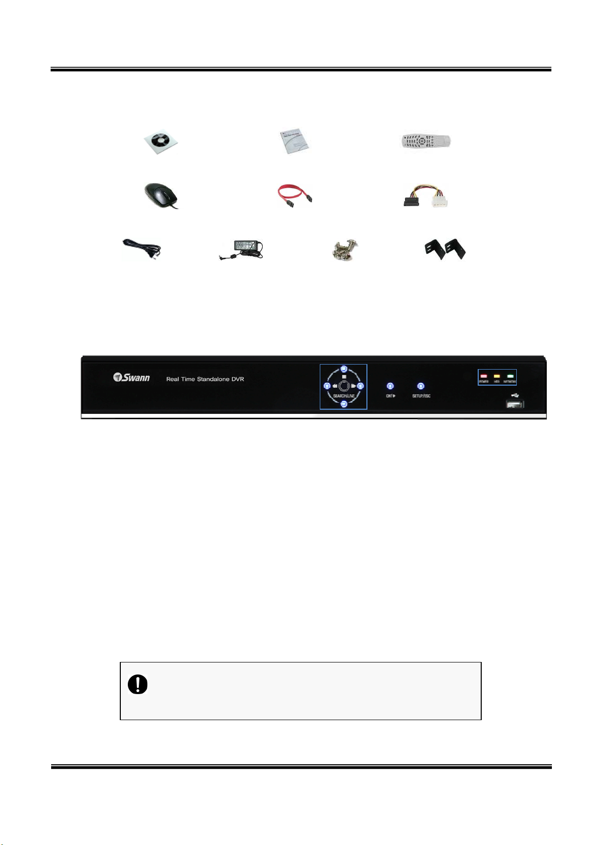
1-2. Contents
USER’S MANUAL
Software Installation CD
User’s Manual
Mouse
Power cable
Reference: The type of components can be applied differently by the option.
Adapter
SATA cable
Screws
Remote Controller
HDD power cable
19” Rack mount
1-3. Front Panel
① Navigation buttons
①
④
⑤
“▼” button is used as navigation key, when menu is shown, on the other hand, it is used for
switching key between SEARCH and LIVE screen when menu not be shown.
② ENTER – This is used to select OSD menu and control playback.
At power off status, it is turned on by pressing “OK” button in some seconds.
At power on status, instant panic recording is executed by pressing “OK” button in some
seconds.
③ SETUP/ESC – This is used to open or close menu.
④ LED
Hard disk LED – This is turned on HDD is accessed.
Power LED – This is turned on when the power is turned on.
Network LED – This is turned on when network is connected.
⑤ USB – This is used to connect USB storage device.
Caution
H.264 REAL TIME DVR
8

USER’S MANUAL
1-4. Rear Panel
① USB port – Used to connect USB storage device, such as a flash drive.
② Main output port – It is used to connect BNC type monitor. (It outputs the same video as MAIN
output.)
③ Camera video input – These are used to connect cameras
④ Audio input port – It is used to connect audio output port of external device.
⑤ External HDD port – It is used to connect e-SATA HDD.
⑥ Sensor/Alarm/RS-485 ports – These are used to connect sensor, alarm and RS-485 serial
communication port
⑦ Mouse port – It is used to connect USB mouse.
⑧ Ethernet port – It is used to connect RJ-45 Ethernet connector. (LAN PORT).
⑨ VGA port – It is used to connect VGA monitor.
⑩ SPOT output port – It is used to connect BNC type monitor.
⑪ Audio output port – It is used to connect audio input port of external device.
⑫ Power connector – It is used to connect power adapter.
H.264 REAL TIME DVR
9

1-5. Remote controller
USER’S MANUAL
Please note: Some DVR models use a remote control with a slightly different shape. The buttons and
their functions are the same.
How to set the ID of remote controller:
1. Press cancel button for about 3 seconds, until the light on the power button lights up.
2. Enter XX, where XX is the two digit numbers which is the ID of remote controller.
※ Remember, when entering a one digit number to input ‘0’ first.
Eg. To set the ID to ‘2’ as ID, input “02”.
3. Each time you press the number key the light of power button will blink.
4. When the power light goes out, the ID is saved.
H.264 REAL TIME DVR
10

1-6. Connection and initial setting
USER’S MANUAL
Caution
Cameras or other external devices can be connected to this device by
When connecting camera(s), ensure that the camera is turned off.
Do not connect power to the DVR until all devices – particularly the
numerous methods. Refer to the user manual of the camera or other
external device(s) for additional information.
monitor – have been properly connected.
H.264 REAL TIME DVR
11

USER’S MANUAL
1-7. RS-485 connection
① This device has 1 data port (RS-485). You can use this
port to connect a PTZ camera or keyboard. (Optional)
② PTZ camera / keyboard connection
i. Connect the PTZ serial communication cable to the
RS-485 port.
ii. When connecting the cable, make sure the polarity
is the right way around. One port is marked “+” and the other marked “-”. See your
PTZ device manual for the correct device polarity, and attach accordingly.
iii. Recommended initial data setting is 9600 baud rate, 8 data bits, 1 stop bit and no
parity. See your PTZ device manual for more information.
iv. When connecting the PTZ camera or keyboard, always change the setting of the DVR
setting menu according the RS-485 setting of the camera, keyboard and this device.
v. If you use a PTZ camera and keyboard together, use the same baud rate for both.
1-8. Control port (output) connection
① To configure the settings for external device use the “Setup Event
Sensor/Motion/Video loss” menu.
② Connect your external output devices to the to the Control Output and Relay ports.
③ Ensure you use the correct port for the devices output status. For example, connect
Normally Open devices (NO) to an NO port, and Normally Closed (NC) devices to an NC port.
See your output device’s manual for more information.
1-9. Sensor (input) connection
① Connect one of the two leads of your sensor(s) (PIR
sensor, magnetic sensor, etc.) to the common
(COM) port and connect the remaining signal cable
to the sensor number you to associate with it.
② Sensor type (“NC” or “NO”) can be set from
Setup
Event Sensor menu.
Note
1 Sensor 1 5 Sensor 5
2 Sensor 2 6 Sensor 6
3 Sensor 3 7 Sensor 7
4 Sensor 4 8 Sensor 8
G Ground G Ground
NC and NO cannot be selected simultaneously.
H.264 REAL TIME DVR
12

USER’S MANUAL
1-10. Internal hard disk installation
To prevent the hard disk in your DVR from being damaged, ensure you handle the DVR carefully. To
prevent any data loss, it is recommended to back up any important data into an external storage device
regularly. When installing or uninstalling the hard disk, you must always disconnect power to the DVR.
If the power is turned on, do not bump, move, knock or drop the DVR.
Do not install this device in a hot and/or humid location, or one where the temperature
changes suddenly.
DO NOT pull out the plug or remove the power supply while this DVR is on.
When there is a power outage while the DVR is turned on, data could be lost.
Do not drop the hard drive or put any metallic object, such as coins, inside the device.
In case of a power outage while recording is in progress, do not replace or move the HDD as
the recorded data can be lost. In this case, turn on the power with the original hard disk that
was used while the power outage occurred and shut down the DVR properly.
Hard disks are precision devices which can be damaged by the smallest of impacts. To ensure
your HDD continues to function reliably:
- Do not directly put the hard disk on the desk or table. Because the parts inside the hard
disk can be damaged at the slightest impact, place suitable padding below the hard disk.
- The parts inside the hard disk can be damaged from excessive vibration. Keep this in mind
when placing or transporting the hard drive and/or DVR.
- When replacing the hard disk, be careful not to cause damage to the other components.
- Be careful not to cause an impact from the tools and hard disk used for the installation.
Protect the hard disk from static electricity. Use a static-free work station when installing or
removing the HDD. Store spare HDDs in static-free bags.
Caution
This device has components which could cause an electric shock, an accident
or a malfunction. If you’re unfamiliar with computer hardware installation
techniques, please consult with a qualified IT or CCTV technician before
attempting any work.
H.264 REAL TIME DVR
13

USER’S MANUAL
1. Hard disk installation of replacement
A. Hard disk installation
After shutting down the DVR, unplug the power from the outlet.
① Loosen the screw on the left, right and rear side of the DVR casing.
② Separate the cover of the main unit.
③ Remove the screws on the bracket holding
the hard disk. Then, separate the bracket
from the hard disk.
④ Install the hard disk to the bracket and tighten the 4 screws.
▶ Connecting bracket to hard disk
Orient the SATA cable connection
port towards the base of the hard
disk bracket, and secure the HDD in
place.
Connect the bracket to hard disk by
tighten the 4 screws
⑤ After installing the bracket on the main unit, tighten the screws.
⑥ Connect the power cable of the hard disk.
⑦ Connect the SATA cable to the hard disk.
⑧ Connect the SATA cable to the SATA port of the main board.
⑨ Close the cover of the main unit.
[Connecting SATA cable] [Connecting power cable]
H.264 REAL TIME DVR
14

USER’S MANUAL
⑩ Tighten the screws on the case.
⑪ After installing the hard disk, you must format the hard disk from the setting
menu.
- The first SATA cable port on the main board must be connected at all times.
If a hard disk is not connected, the DVR may not operate normally (or at all).
B. Hard disk replacement
After shutting down the DVR, disconnect the power supply.
① Loosen the screws on the left, right and rear side of the DVR casing.
② Remove the cover of the main unit.
③ After removing all of power/SATA cable connected to hard disk, separate
hard disk bracket from the body.
④ Loosen the screws on the left and right side of the bracket holding the hard
disk.
⑤ Separate the hard disk from the bracket holding the hard disk.
⑥ In the reverse order of removing the hard disk, assemble the new hard disk.
⑦ After replacing the hard disk, turn on the power of the device.
⑧ Reference
- Each SATA cable must be connected to the connecting port precisely.
- Do not vertically put the hard disk in upright position or put other objects on
top of the hard disk.
- When connecting/disconnecting the hard disk, do not use a motored tool.
- Refer to the following when adding/replacing the hard disk.
H.264 REAL TIME DVR
15

USER’S MANUAL
Manufacturer
Model name
Capacity
ST3250312CS
ST3250310
CS ST35003
12CS 500G
B ST3750330SV
750G
B
ST31
99322CS
1TB
WD1600AAJS
160GB
WD25
2
00AAJS
WD2500AV
VS
WD5000AACS
WD5000AAVS
WD10EACS
1TB WD15EARS
1.5TB
C. Recommended list of hard disk
- Hard disks of below are the ones proved to be compatible through experiment.
- Please refer to when adding or replacing the hard disk.
250GB
Seagate
250G
Western Digital
Caution
When you select the hard drive in use for resetting, the video
data saved previously will be deleted. Therefore you must be
careful.
500G
H.264 REAL TIME DVR
16

C
C
H
APPTTEERR
H
A
2
2
USER’S MANUAL
Maaiinn SSyyssttee
M
2-1 Operation -------------------------------------------------------------------------- 18
Start up ..................................................................................... 18
Shutdown ..................................................................................... 19
2-2 Live Display ----------------------------------------------------------------------- 20
2-3 System setting -------------------------------------------------------------------- 24
System ........................................................................................ 24
Video/Audio ................................................................................. 29
Event .......................................................................................... 34
Network ...................................................................................... 38
User ........................................................................................... 42
m AApppplliiccaattiioonn
m
2-4 PTZ Control ----------------------------------------------------------------------- 45
2-5 Search (playback) & backup ---------------------------------------------------- 47
Time search .................................................................................. 47
Event search ................................................................................. 48
Backup ........................................................................................ 49
H.264 REAL TIME DVR
17

I. “
admin
” means
System Administrator
2-1. Operation
1) Start up
1. Turn on the DVR. The power indicator light will turn on.
2. Once the DVR boots, you’ll need to log in. Until you log in, the DVR will use the LOGOUT id.
USER’S MANUAL
3. Pressing
username and press “OK” button to continue.
①
[USER]
You may select user to login and authority is restricted by kind of user. The access
button, then the login window would be displayed. Select the desired
rights can be set for each user.
⑨
②
[PASSWORD]
The default user and password are set to ‘admin’ and ‘000000’.
Click password input area; you will see the screen keypad as right.
4. Input password by using virtual keypad on screen.
5. Click “OK” button to log in to the DVR system and you will see live screen.
Allows access to: Live Viewing, Search Functions and Setup Options
II. user1/user2/user3 for General Users
Individual users access rights can be set by the Administrator
○12
H.264 REAL TIME DVR
18

2) Shutdown
1. Whilt you are logged in as a user with sufficient rights, press the
logout window will be displayed, as shown below.
USER’S MANUAL
button and the
A. SELECTION: Select Logout or EXIT.
B. USER: Display current user has logged.(admin /user1/user2/user3)
C. PASSWORD: Where you input your password.
2. Click “OK” button to “Log Out” (locks the DVR) or “DVR Shutdown” (shuts down the DVR
completely – it will not record anything whilst in shutdown).
H.264 REAL TIME DVR
19

2-2. Live Display
①
③
USER’S MANUAL
②
④
①
[Camera name]
Shows camera name
If you want to modify camera name, you can do so by selecting [Setup] [Camera]
②
[Status icon] (OSD)
Status icon shows current status of the channel.
The OSD (On-Screen Display) icons are as follows:
[Channel]
Camera
Recording
Item Icon
⑤
Description
Audio icon
Motion icon
PTZ icon
Continuous recording
Immediate recording
Recording by motion
No recording
Recording by sensor
H.264 REAL TIME DVR
20

USER’S MANUAL
⑨ ⑧ ⑦ ⑥ ⑤ ④ ③ ② ①
③
[Channel selection]
The selected channel shows is highlighted by a red rectangle.
Press “OK” button on the remote control to enlarge selected channel to full screen.
④
[Live view]
It shows current live view in real-time.
⑤ [System control toolbar – Live screen]
⑩ ⑪
To hide live toolbar, right click the screen or press “live” button on the remote controller.
1) [Setup]
Click
button to enter the Settings Menu
Refer to Chapter “2-3 System setting” for more information.
2) [Search]
Click
button to enter search screen.
Refer to Chapter “2-5 Search (playback) & backup” for more information.
3) [Divided screen selection]
The screen can be divided into 1, 4, 9, 13 or 16 channel views.
4) [
Auto sequence]
Click button and each channel will be switched automatically.
This function does not work at 16 divided screens.
You can set the switching interval at [Setup] [System] [Overview] [Auto-
switching].
5) [
PTZ control
]
This is the button to control the PTZ camera
Refer to Chapter “2-4 PTZ control” for more information.
6) [
Alarm on/off
]
This button is used to turn the alarm output ON or OFF.
H.264 REAL TIME DVR
21

USER’S MANUAL
7) [
System Log]
This accesses the system log in DVR.
Click the
You can see the log of previous date or next date by using ◀ / ▶ button.
You can see the previous or next log list by using (-) / (+) button.
Click “OK” to close the System Log window.
8) [
Information
It shows the system information.
button to show the System Log list.
]
9) [
Login/Logout
Can be used to login into, logout of or shutdown the DVR.
10) [
Touch button]
It is used to enable/disable the touch buttons on the front of the DVR.
It can protect accidental triggering of the touch-sensitive buttons.
11) [
Network status display
It shows the current status of your network connection.
If you want to modify network settings, you can do so by selecting [Setup]
[Network] [TCP/IP]
]
]
(Black: The network is disconnected.)
(Blue: The network is connected.)
H.264 REAL TIME DVR
22
 Loading...