

Page 1

AlphaPC 164UX/BX Motherboard
Windows NT
User’s Manual
Page 2

Notice
The information in this publication has been carefully checked and is believed to be entirely accurate at the time of publication.
Samsung assumes no responsibi lity, however, for possible errors or omissions, or for an y consequences resulting from the use
of the information cont a ine d herein.
Samsung reserves the rig ht to m ake changes in its products or prod uct specifications with the in tent to improve function or
design at any time and without notic e and is not required to update this docume ntation to reflect s uch changes.
This publication does not convey to a purchaser of semiconductor devices described herein any license under the patent rights of
Samsung or others.
AlphaPC 164UX/BX Motherboard
Windows NT
User’s Manual
©1998 Samsung Electronics
All rights reserved. No part of this publication may be reproduced, stored in a retrieval system, or transmitted in any form or by
any means, electric or mec hanical, by photocopyi ng, rec ordi ng, or otherwise, without the prior written consent of Samsung
Electronics.
Alpha, Digital Semico nduc tor are trademarks of Digit al Equ ipment Corporation.
Samsung and Samsung logo are trademarks of Sams ung Electronics Co., Ltd.
FaxBACK and Intel are registered trademarks of Intel Corporation.
GRAFOIL is a registered trademark of Union Carb ide Cor poration.
Microsoft, MS-DOS, Windows, and Windows 95 are registered tr ade marks and Windows NT is a trademark of Microsoft
Corporation.
QLogic is a registered trademark of QLogic Corpor at ion.
SMC is a registered trademar k of Standa rd Mi crosystems Corporation.
UNIX is a registered trademark in the United States and other countries licensed exclusively through X/Open Company Ltd.
Xilinx is a trademark of Xi li nx, Incorporated.
All other trademarks and registered tradem arks are the property of their respective owners.
San #24 Nongseo-ri , Kiheung-eup
Yongin-city, Kyungki-do, Korea
449-900
FAX : 82-331-209-4492
TEL : 82-331-209-3282
Printed in the Republic of Kore a
Page 3

Contents
1 About This Manual
1.1 Difference between AlphaPC 164UX and 164BX. . . . . . . . . . . . . . . . . . . . . . . . . 1–1
1.2 Manual Conventions and Terminology . . . . . . . . . . . . . . . . . . . . . . . . . . . . . . . . . 1–1
2 Features of the AlphaPC 164UX Motherboard
2.1 Power Requirements . . . . . . . . . . . . . . . . . . . . . . . . . . . . . . . . . . . . . . . . . . . . . . 2–4
2.2 Environmental Requirements . . . . . . . . . . . . . . . . . . . . . . . . . . . . . . . . . . . . . . . . 2–4
2.3 Physical Parameters. . . . . . . . . . . . . . . . . . . . . . . . . . . . . . . . . . . . . . . . . . . . . . . 2–5
2.3.1 Board Measurements and Hole Locations. . . . . . . . . . . . . . . . . . . . . . . . . . . 2–5
2.3.2 Vertical Clearance . . . . . . . . . . . . . . . . . . . . . . . . . . . . . . . . . . . . . . . . . . . . . 2–6
2.3.3 ATX Cutout Information. . . . . . . . . . . . . . . . . . . . . . . . . . . . . . . . . . . . . . . . . 2–8
3 AlphaPC 164UX Jumper Configuration
3.1 CPU Speed Selection (Option 1,2,3,&4). . . . . . . . . . . . . . . . . . . . . . . . . . . . . . . . 3–2
3.2 Bcache Size Jumpers (Option 14,15). . . . . . . . . . . . . . . . . . . . . . . . . . . . . . . . . . 3–3
3.3 Boot Option Jumper (Option 11). . . . . . . . . . . . . . . . . . . . . . . . . . . . . . . . . . . . . . 3–3
4 AlphaPC 164UX Connector Pinouts
4.1 PCI Bus Connector Pinouts . . . . . . . . . . . . . . . . . . . . . . . . . . . . . . . . . . . . . . . . . 4–1
4.2 ISA Expansion Bus Connector Pinouts. . . . . . . . . . . . . . . . . . . . . . . . . . . . . . . . . 4–3
4.3 SDRAM DIMM Connector Pinouts . . . . . . . . . . . . . . . . . . . . . . . . . . . . . . . . . . . . 4–4
4.4 EIDE Drive Bus Connector Pinouts. . . . . . . . . . . . . . . . . . . . . . . . . . . . . . . . . . . . 4–5
4.5 Diskette Drive Bus Connector Pinouts . . . . . . . . . . . . . . . . . . . . . . . . . . . . . . . . . 4–6
4.6 Parallel Bus Connector Pinouts . . . . . . . . . . . . . . . . . . . . . . . . . . . . . . . . . . . . . . 4–6
4.7 COM1/COM2 Serial Line Connector Pinouts . . . . . . . . . . . . . . . . . . . . . . . . . . . . 4–7
4.8 Keyboard/Mouse Connector Pinouts . . . . . . . . . . . . . . . . . . . . . . . . . . . . . . . . . . 4–7
iii
Page 4

4.9 Input Power Connector Pinouts . . . . . . . . . . . . . . . . . . . . . . . . . . . . . . . . . . . . . . 4–8
4.10 Narrow SCSI Bus Connector (UX only) . . . . . . . . . . . . . . . . . . . . . . . . . . . . . . . . 4–8
4.11 Fast and Wide SCSI Bus Connector (UX only). . . . . . . . . . . . . . . . . . . . . . . . . . . 4–9
4.12 10/100 Mbit Ethernet Connector Pinouts (UX only) . . . . . . . . . . . . . . . . . . . . . . . 4–9
4.13 Speaker Connector Pinouts . . . . . . . . . . . . . . . . . . . . . . . . . . . . . . . . . . . . . . . . . 4–10
4.14 Microprocessor Fan Power Connector Pinouts. . . . . . . . . . . . . . . . . . . . . . . . . . . 4–10
4.15 Pin Power LED Connector Pinouts. . . . . . . . . . . . . . . . . . . . . . . . . . . . . . . . . . . . 4–10
4.16 IDE Drive LED Connector Pinouts . . . . . . . . . . . . . . . . . . . . . . . . . . . . . . . . . . . . 4–11
4.17 Reset Button Connector Pinouts. . . . . . . . . . . . . . . . . . . . . . . . . . . . . . . . . . . . . . 4–11
4.18 Soft Power Switch Connector Pinouts . . . . . . . . . . . . . . . . . . . . . . . . . . . . . . . . . 4–11
4.19 SCSI LED Connector Pinouts. . . . . . . . . . . . . . . . . . . . . . . . . . . . . . . . . . . . . . . . 4–11
5 Memory and Microprocessor Configuration
5.1 Configuring SDRAM Memory . . . . . . . . . . . . . . . . . . . . . . . . . . . . . . . . . . . . . . . . 5–1
5.2 Upgrading SDRAM Memory . . . . . . . . . . . . . . . . . . . . . . . . . . . . . . . . . . . . . . . . . 5–3
5.3 Increasing Microprocessor Speed. . . . . . . . . . . . . . . . . . . . . . . . . . . . . . . . . . . . . 5–4
5.3.1 Preparatory Information. . . . . . . . . . . . . . . . . . . . . . . . . . . . . . . . . . . . . . . . . 5–4
5.3.2 Required Tools . . . . . . . . . . . . . . . . . . . . . . . . . . . . . . . . . . . . . . . . . . . . . . . 5–4
5.3.3 Removing the 21164 Microprocessor . . . . . . . . . . . . . . . . . . . . . . . . . . . . . . 5–5
5.3.4 Installing the 21164 Microprocessor . . . . . . . . . . . . . . . . . . . . . . . . . . . . . . . 5–5
6 Interrupts and ISA Bus Addresses
6.1 Interrupts. . . . . . . . . . . . . . . . . . . . . . . . . . . . . . . . . . . . . . . . . . . . . . . . . . . . . . . . 6–1
6.2 ISA I/O Address Map . . . . . . . . . . . . . . . . . . . . . . . . . . . . . . . . . . . . . . . . . . . . . . 6–2
6.2.1 Flash ROM Address Map . . . . . . . . . . . . . . . . . . . . . . . . . . . . . . . . . . . . . . . 6–2
7 Configuring for Windows NT
7.1 ARCSBIOS . . . . . . . . . . . . . . . . . . . . . . . . . . . . . . . . . . . . . . . . . . . . . . . . . . . . . . 7–1
7.1.1 Navigating the ARCSBIOS . . . . . . . . . . . . . . . . . . . . . . . . . . . . . . . . . . . . . . 7 –1
7.1.2 Exploring the ARCSBIOS . . . . . . . . . . . . . . . . . . . . . . . . . . . . . . . . . . . . . . . 7–1
7.2 ARCSBIOS Setup. . . . . . . . . . . . . . . . . . . . . . . . . . . . . . . . . . . . . . . . . . . . . . . . . 7–3
7.2.1 Run a Program . . . . . . . . . . . . . . . . . . . . . . . . . . . . . . . . . . . . . . . . . . . . . . . 7–3
7.2.2 Environment Variables. . . . . . . . . . . . . . . . . . . . . . . . . . . . . . . . . . . . . . . . . . 7–4
7.2.3 Advanced Setup . . . . . . . . . . . . . . . . . . . . . . . . . . . . . . . . . . . . . . . . . . . . . . 7–4
7.2.4 System Time and Date . . . . . . . . . . . . . . . . . . . . . . . . . . . . . . . . . . . . . . . . . 7–5
7.2.5 System Configuration . . . . . . . . . . . . . . . . . . . . . . . . . . . . . . . . . . . . . . . . . . 7–5
7.2.6 Print Configuration. . . . . . . . . . . . . . . . . . . . . . . . . . . . . . . . . . . . . . . . . . . . . 7–6
7.2.7 Add-in Board Utilities. . . . . . . . . . . . . . . . . . . . . . . . . . . . . . . . . . . . . . . . . . . 7–6
7.3 Upgrading the ARCSBIOS Firmware . . . . . . . . . . . . . . . . . . . . . . . . . . . . . . . . . . 7–6
7.4 Installing Windows NT . . . . . . . . . . . . . . . . . . . . . . . . . . . . . . . . . . . . . . . . . . . . . 7–6
iv
Page 5

7.4.1 Requirements . . . . . . . . . . . . . . . . . . . . . . . . . . . . . . . . . . . . . . . . . . . . . . . . 7–6
7.4.2 Before Installing Windows NT . . . . . . . . . . . . . . . . . . . . . . . . . . . . . . . . . . . . 7–7
7.4.3 Windows NT Setup . . . . . . . . . . . . . . . . . . . . . . . . . . . . . . . . . . . . . . . . . . . . 7–9
8 Troubleshooting
8.1 Hardware Startup . . . . . . . . . . . . . . . . . . . . . . . . . . . . . . . . . . . . . . . . . . . . . . . . . 8–1
8.1.1 Troubleshooting steps: No Video. . . . . . . . . . . . . . . . . . . . . . . . . . . . . . . . . . 8–1
8.1.2 Troubleshooting steps: Keyboard error on boot up . . . . . . . . . . . . . . . . . . . . 8–1
8.2 Beep Codes . . . . . . . . . . . . . . . . . . . . . . . . . . . . . . . . . . . . . . . . . . . . . . . . . . . . . 8–2
8.3 Post Codes . . . . . . . . . . . . . . . . . . . . . . . . . . . . . . . . . . . . . . . . . . . . . . . . . . . . . . 8–2
8.4 Safe ARCSBIOS. . . . . . . . . . . . . . . . . . . . . . . . . . . . . . . . . . . . . . . . . . . . . . . . . . 8–3
8.4.1 Starting the Safe ARCSBIOS . . . . . . . . . . . . . . . . . . . . . . . . . . . . . . . . . . . . 8–4
9 Battery Recycle/Disposal Information
A Supporting Products
A.1 Memory. . . . . . . . . . . . . . . . . . . . . . . . . . . . . . . . . . . . . . . . . . . . . . . . . . . . . . . . . A–1
A.2 Thermal Products . . . . . . . . . . . . . . . . . . . . . . . . . . . . . . . . . . . . . . . . . . . . . . . . . A–3
A.3 Power Supply . . . . . . . . . . . . . . . . . . . . . . . . . . . . . . . . . . . . . . . . . . . . . . . . . . . . A–3
A.4 Enclosure . . . . . . . . . . . . . . . . . . . . . . . . . . . . . . . . . . . . . . . . . . . . . . . . . . . . . . . A–4
B Support,Products and Documentation
v
Page 6

Figures
2–1 AlphaPC 164UX Jumper/Connector Location. . . . . . . . . . . . . . . . . . . . . . . . . . . . 2–2
2–2 Board measurement and Hole Position Diagram . . . . . . . . . . . . . . . . . . . . . . . . . 2–6
2–3 Board Vertical Clearance Diagram . . . . . . . . . . . . . . . . . . . . . . . . . . . . . . . . . . . . 2–7
2–4 ATX Back Panel Dimension . . . . . . . . . . . . . . . . . . . . . . . . . . . . . . . . . . . . . . . . . 2–8
3–1 AlphaPC 164UX Configuration Jumpers. . . . . . . . . . . . . . . . . . . . . . . . . . . . . . . . 3–2
5–1 Fan/Heat-Sink Assembly . . . . . . . . . . . . . . . . . . . . . . . . . . . . . . . . . . . . . . . . . . . 5–6
7–1 Main Bios Screen . . . . . . . . . . . . . . . . . . . . . . . . . . . . . . . . . . . . . . . . . . . . . . . . . 7–2
vi
Page 7

Tables
2–1 AlphaPC 164UX Features. . . . . . . . . . . . . . . . . . . . . . . . . . . . . . . . . . . . . . . . . . . 2–1
2–2 AlphaPC 164UX Jumper/Connector List. . . . . . . . . . . . . . . . . . . . . . . . . . . . . . . . 2–3
2–3 Power Supply DC Current Requirements. . . . . . . . . . . . . . . . . . . . . . . . . . . . . . . 2–4
2–4 AlphaPC 164UX Motherboard Environmental Requirements. . . . . . . . . . . . . . . . 2–4
4–1 PCI Bus Connector Pinouts . . . . . . . . . . . . . . . . . . . . . . . . . . . . . . . . . . . . . . . . . 4–1
4–2 ISA Expansion Bus Connector Pinouts (J10) . . . . . . . . . . . . . . . . . . . . . . . . . . . . 4–3
4–3 SDRAM DIMM Connector Pinouts (U3 through U8). . . . . . . . . . . . . . . . . . . . . . . 4 –4
4–4 EIDE Drive Bus Connector Pinouts (J24). . . . . . . . . . . . . . . . . . . . . . . . . . . . . . . 4–5
4–5 Diskette (Floppy) Drive Bus Connector Pinouts (J33). . . . . . . . . . . . . . . . . . . . . . 4–6
4–6 Parallel Bus Connector Pinouts (J13). . . . . . . . . . . . . . . . . . . . . . . . . . . . . . . . . . 4–6
4–7 COM1/COM2 Serial Line Connector Pinouts (J12). . . . . . . . . . . . . . . . . . . . . . . . 4–7
4–8 Keyboard/Mouse Connector Pinouts (J25). . . . . . . . . . . . . . . . . . . . . . . . . . . . . . 4–7
4–9 Input Power Connector Pinouts (J18). . . . . . . . . . . . . . . . . . . . . . . . . . . . . . . . . . 4–8
4–10 Narrow SCSI Bus Connector (J16). . . . . . . . . . . . . . . . . . . . . . . . . . . . . . . . . . . . 4–8
4–11 Fast and Wide SCSI Bus Connector Pinouts (J15). . . . . . . . . . . . . . . . . . . . . . . . 4–9
4–12 10/100 Mbit Ethernet Connector Pinouts (J34). . . . . . . . . . . . . . . . . . . . . . . . . . . 4–9
4–13 Speaker Connector Pinouts (J23). . . . . . . . . . . . . . . . . . . . . . . . . . . . . . . . . . . . . 4–10
4–14 Microprocessor Fan Power Connector Pinouts (J35). . . . . . . . . . . . . . . . . . . . . . 4–10
4–15 Power LED Connector Pinouts (J31) . . . . . . . . . . . . . . . . . . . . . . . . . . . . . . . . . . 4–10
4–16 IDE Drive LED Connector Pinouts (J29). . . . . . . . . . . . . . . . . . . . . . . . . . . . . . . . 4–11
4–17 Reset Button Connector Pinouts (J37) . . . . . . . . . . . . . . . . . . . . . . . . . . . . . . . . . 4–11
4–18 Soft Power Switch Connector Pinouts (J36). . . . . . . . . . . . . . . . . . . . . . . . . . . . . 4–11
4–19 SCSI LED Connector Pinouts (J17) . . . . . . . . . . . . . . . . . . . . . . . . . . . . . . . . . . . 4–11
5–1 AlphaPC 164UX SDRAM Memory Configurations . . . . . . . . . . . . . . . . . . . . . . . . 5–1
6–1 ISA Interrupts . . . . . . . . . . . . . . . . . . . . . . . . . . . . . . . . . . . . . . . . . . . . . . . . . . . . 6–1
6–2 ISA I/O Address Map . . . . . . . . . . . . . . . . . . . . . . . . . . . . . . . . . . . . . . . . . . . . . . 6–2
7–1 Navigation Keys . . . . . . . . . . . . . . . . . . . . . . . . . . . . . . . . . . . . . . . . . . . . . . . . . . 7–1
8–1 Beep Codes . . . . . . . . . . . . . . . . . . . . . . . . . . . . . . . . . . . . . . . . . . . . . . . . . . . . . 8–2
8–2 Post Codes. . . . . . . . . . . . . . . . . . . . . . . . . . . . . . . . . . . . . . . . . . . . . . . . . . . . . . 8–3
A–1 Samsung DIMM Part Number List . . . . . . . . . . . . . . . . . . . . . . . . . . . . . . . . . . . . A–1
A–2 VisionTek DIMM Part Number List . . . . . . . . . . . . . . . . . . . . . . . . . . . . . . . . . . . . A–2
A–3 Viking Components DIMM Part Number List . . . . . . . . . . . . . . . . . . . . . . . . . . . . A–2
A–4 QesTec DIMM Part Number List. . . . . . . . . . . . . . . . . . . . . . . . . . . . . . . . . . . . . . A–2
A–5 Dense-Pac Microsystems DIMM Part Number List. . . . . . . . . . . . . . . . . . . . . . . . A–3
vii
Page 8

1
About This Manual
This manual describes the AlphaPC 164UX/BX motherboard, a module for
computing systems based on the Alpha
Digital Semiconductor 21 174 core logic chip. It describes the mothe rboard’s fe atures
and how to set its configuration jumpers. This manual helps users to install and
populate the AlphaPC 164UX/BX motherboard with memory modules and
peripheral cards.
TM
21164 micr oproce ssor a nd the co mpani on
1.1 Difference between AlphaPC 164UX and 164BX
• AlphaPC 164UX motherboard has the Ethernet LAN Controller and Ultra Wide
SCSI Controller which are not on AlphaPC 164BX motherboard.
• The size of AlphaPC 164BX motherboard’s L3 cache is 2MB.
• The size of AlphaPC 164UX motherboard’s L3 cache is 2MB or 4MB.
• Except the above, AlphaPC 164UX motherboard and 164BX motherboard are
the same.
• The following sections are about AlphaPC 164UX motherboard only.
1.2 Manual Conventions and Terminology
The following conventions are used in this manual.
Caution: Cautions indicate potential damage to equipment, software, or data.
Note: Notes provide additional information about a topic.
Numbering: All numbers a re dec imal or hexade cimal un less otherwi se ind icate d. In
case of ambiguity, a subscript indicates the radix of nondecimal numbers. For
example, 19 is a decimal number, but 19
and 19A are hexadecimal numbers.
16
About This Manual 1–1
Page 9

Manual Conventions and Terminology
Extents: Extents are specified by a single number or a pair of numbers in square
brackets ([ ]) separated by a colon (:), and are inclusive. For example, bits [7:3]
specify an extent including bits 7, 6, 5, 4, and 3. Multiple bit fields are shown as
extents.
Register Figures: Register figures have bit and field position numbering starting at
the right (low-order) and increasing to the left (high-order).
Signal Names: All signal names are printed in boldface type. Signal names that
originate in an indu stry- stand ard spe cifi catio n, such a s PCI or IDE, are p rint ed in t he
case as found in the spe cificat ion ( usuall y u pperca se). Acti ve lo w sign als ha ve either
a pound sign “#” appended, or a “not” overscore bar; for example, DEVSEL# and
RESET
Italic Type: Italic type emphasizes important information and indicates complete
titles of documents.
Terms: The following terms are used in this manual:
This term... Refers to...
Microsoft Windows NT installation
guide
Windows NT The Microsoft Windows NT Workstation and the
.
The Microsoft Windows NT Workstation
Installation Guide and the Windows NT Server
Installation Guide.
Windows NT Server operating systems.
1–2 About This Manual
Page 10

2
Features of the AlphaPC164UX Motherboard
Table 2–1 provides an overview of the AlphaPC 164UX motherboard’s features.
Table 2–1 AlphaPC 164UX Features
Feature Description
Microprocessor Alpha 21164 microprocessor (64-bit RISC)
Core logic chip Digital Semiconducto r 21174 core logi c chip, comprising a single
control chip that provides an interface to system memory and the
PCI bus
Main memory 32MB to 3GB memory array –- Three banks of 128-bit memory;
168-pin unbuffered SDRAM DIMMs with ECC
Caching:
L1 Icache 8KB, direct-mapped instruc tion cache on the CPU chip
L1 Dcache 8KB, direct-mapped data cache on the CPU chip
L2 Scache 96KB, three-way, set-associative, write-back unified instruction
and data cache on the CPU chip
L3 backup cache Onboard 2MB/4MB, direct-mapped, synchronous SSRAM backup
cache with 128-bit data path
I/O and miscellaneous support 32-bit and 64-bit, 33-MHz PCI
One 64-bit and five 32-bit PCI expansion slots
One dedicated ISA expansi on slot
DEC 21052 PCI-to-PCI Bridge chip
Intel 82371SB PCI-to-ISA bridge chip
DEC 21143 10/100 Mb/s Ethernet LAN Controller
Symbios 53C875 Ultra wide SCSI Controller
SMC FDC37C666 co mbination controller chip provides control
for diskettes, two UARTs with modem control, parallel port
1MB flash ROM
Firmware Windows NT ARCSBIOS firmware
Figure 2–1 shows the AlphaPC 164UX motherboard and its components.
Features of the AlphaPC164UX Motherboard 2–1
Page 11
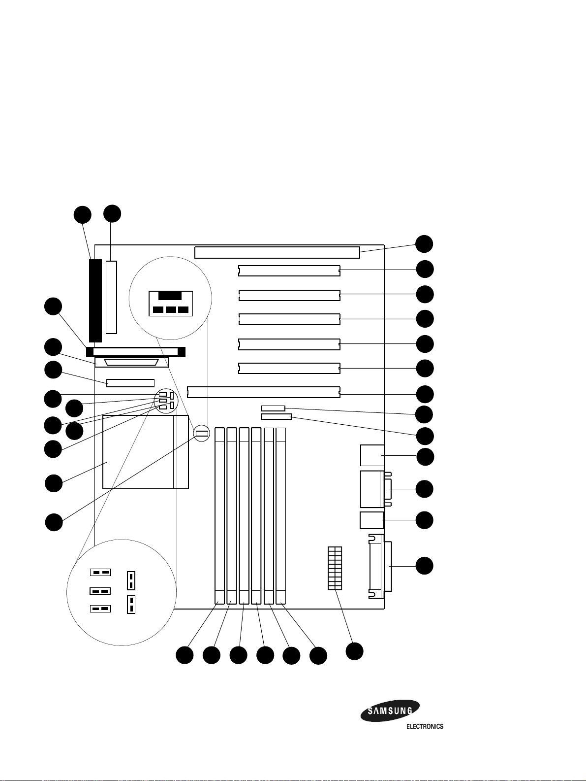
Figure 2–1 AlphaPC 164UX Jumper/Connector Location
J16
J15
J28
J30
J29
J17
U55
J36
J37
J33
J24
Blk
wire
GND
Yellow
wire
FOK
+12
Red
wire
J10
J22
J21
J7
J6
J5
J2
J23
J31
J34
J12
J35
Pwr LED
IDE LED
SCSI LED
Pwr
Switch
Reset
Switch
U7U8
2–2 Features of the AlphaPC164UX Motherboard
J25
J13
U5U6
U3U4
J18
Page 12

Table 2–2 AlphaPC 164UX Jumper/Connector List
Item
No. Description Item No. Description
J2 Full length 64 bit PCI slot U3 DIMM socket 0
J5 Half length 32 bit PCI slot U4 DIMM socket 1
J6 Full length 32 bit PCI slot U5 DIMM socket 2
J7 Full length 32 bit PCI slot U6 DIMM socket 3
J10 Full length ISA slot U7 DIMM socket 4
J12 Serial Port connector U8 DIMM socket 5
J13 Parallel port connector U55 Microprocessor socket(21164 Alpha)
J15 Ultra Fast and Wide SCSI Connector
J16 Narrow SCSI connector
J17 SCSI LED connector
J18 Power connector
J21 Full length 32 bit PCI slot
J22 Full length 32 bit PCI slot
J23 Speaker connector
J24 IDE drive connector
J25 Keyboard/Mouse connector
J28 Configuration jumpers
J29 IDE LED connector
J30 2 pin Power LED connect or
J31 5 pin Power LED connect or
J33 Floppy drive connector
J34 10/100 Mbit ethernet connector
J35 Microprocessor fan/fan sense connector
J36 Power switch connector
J37 Reset switch connector
Features of the AlphaPC164UX Motherboard 2–3
Page 13

Power Requirements
2.1 Power Requirements
The AlphaPC 164UX motherboard requires a minimum of a 300 watt power supply.
The power supply must be ATX-compliant.
Table 2–3 Power Supply DC Current Requirements
Voltage Current
+3.3Vdc,±5% 14 A
+5 Vdc,
-5 Vdc,
+12 Vdc,
-12 Vdc,
Caution: Fan sensor required. The 21164 microprocessor cooling fan must
±5% 25 A
±5% 0.5 A
±5% 10 A
±5% 0.5 A
have a built-in sensor that will drive a signal if the airflow stops. The
sensor is connected to the motherboard connector J35. When the signal
is generated, the speaker generates a tone..
2.2 Environmental Requirements
The 21164 microprocessor is cooled by a small fan blowing directly into the chip’s
heat sink. The AlphaPC 164UX motherboard is designed to run efficiently using
only this fan. Additional fans may be necessary depending upon cabinetry and the
requirements of add-in cards and disk drives.
The AlphaPC 164UX motherboard is specified to run within the environment listed
in T able 2–4.
Table 2–4 AlphaPC 164UX Motherboard Environmental Requirements
Parameter Specification
Operating Temperature 10°C to 40°C (50°F to 104°F)
Storage Temperature -55°C to 125°C ( -67°F to 257°F)
Relative Humidity 10% to 90% with ma ximum wet bulb temperature 28°C
(82°F) and a minimum dew point 2°C (36°F)
Rate of (dry bulb) temperature
change
2–4 Features of the AlphaPC164UX Motherboard
11°C/hour
±2°C/hour (20°F/hour ±4°F/hour)
Page 14

2.3 Physical Parameters
This section has two parts: the first illustrates the distances between the board
mounting holes and the edges of the board; the second shows the vertical clearances
required by the board components at all points within the border of the AlphaPC
164UX.
All holes and board measurements are compliant with the ATX 2.01 specification.
The AlphaPC 164UX exceeds the ATX height indications in two places. The first is
at the location of the 21164 (the 2.5’ region).The second is at the location of the
SCSI connectors(the 1.0’ region to the left of the second PCI slots).
The AlphaPC motherboard is an ATX-size printed wiring board (PWB) with the following dimensions:
• Length: 30.48 cm (12.0 in ( 0.0005 in)
• Width: 24.38 cm (9.6 in ( 0.0005 in)
• Height: 6.86 cm (2.7 in)
The board can be used in certain desktop and deskside systems that have adequate
clearance for the 21164 heat sink and its cooling fan. All ISA and PCI expansion
slots are usable in standard desktop or deskside enclosures.
Physical Parameters
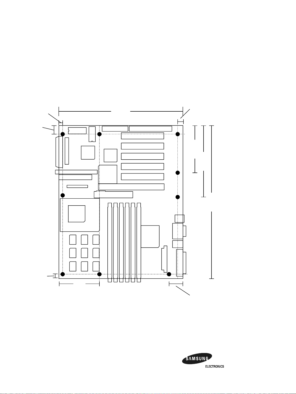
2.3.1 Board Measurements and Hole Locations
Figure 2–2 shows the Board measurements and hole locations for the AlphaPC
164UX
Features of the AlphaPC164UX Motherboard 2–5
Page 15
Physical Parameters
Figure 2–2 Board measurement and Hole Position Diagram
.25 0"
.65 0"
9.600"
.40 0"
3.750"
5.550"
12.00"
.25 0"
3.1"
B oard M easurement s and Hole Locat ion s
2.3.2 Vertical Clearance
Figure 2–3 shows the Board Vertical Clearance for the AlphaPC 164UX
2–6 Features of the AlphaPC164UX Motherboard
1.300"
Page 16

Figure 2–3 Board Vertical Clearance Diagram
0.5"
1.0"
2.5"
Physical Parameters
0.5"
V ert ical Clea rance Requirem ent s
1.5"
1.5"
Features of the AlphaPC164UX Motherboard 2–7
1.0"
Page 17

Physical Parameters
n
2.3.3 ATX Cutout Information
In the event that an OEM or system integrator would like to use a chassis that supports a
standard ATX back-panel cutout, we have included the mechanical drawing used to create
standard cutout.
Figure 2–4 ATX Back Panel Dimension
Standard 9 pin DSUB
connector cutouts
with these center
points
Standard 25 pin
DSUB connector
cutout with this center
point
4.924
.856
.247
Radius = .490 on both
circles. Dimensions
represent center of
.256
circles.
6.250
3.454
2.436
1.774
.640
.990
.240
1.134
0.54
.020
1.60
.150
2–8 Features of the AlphaPC164UX Motherboard
Page 18

3
AlphaPC 164UX Jumper Configuration
The AlphaPC 164UX has one set of jumpers located at J28. These jumpers set the
hardware configuration and boot options. Figure 2–1 shows the jumper location on
the AlphaPC 164UX motherboard. Figure 3–1 shows the jumper functions for each
group.
AlphaPC 164UX Jumper Configura t ion 3–1
Page 19
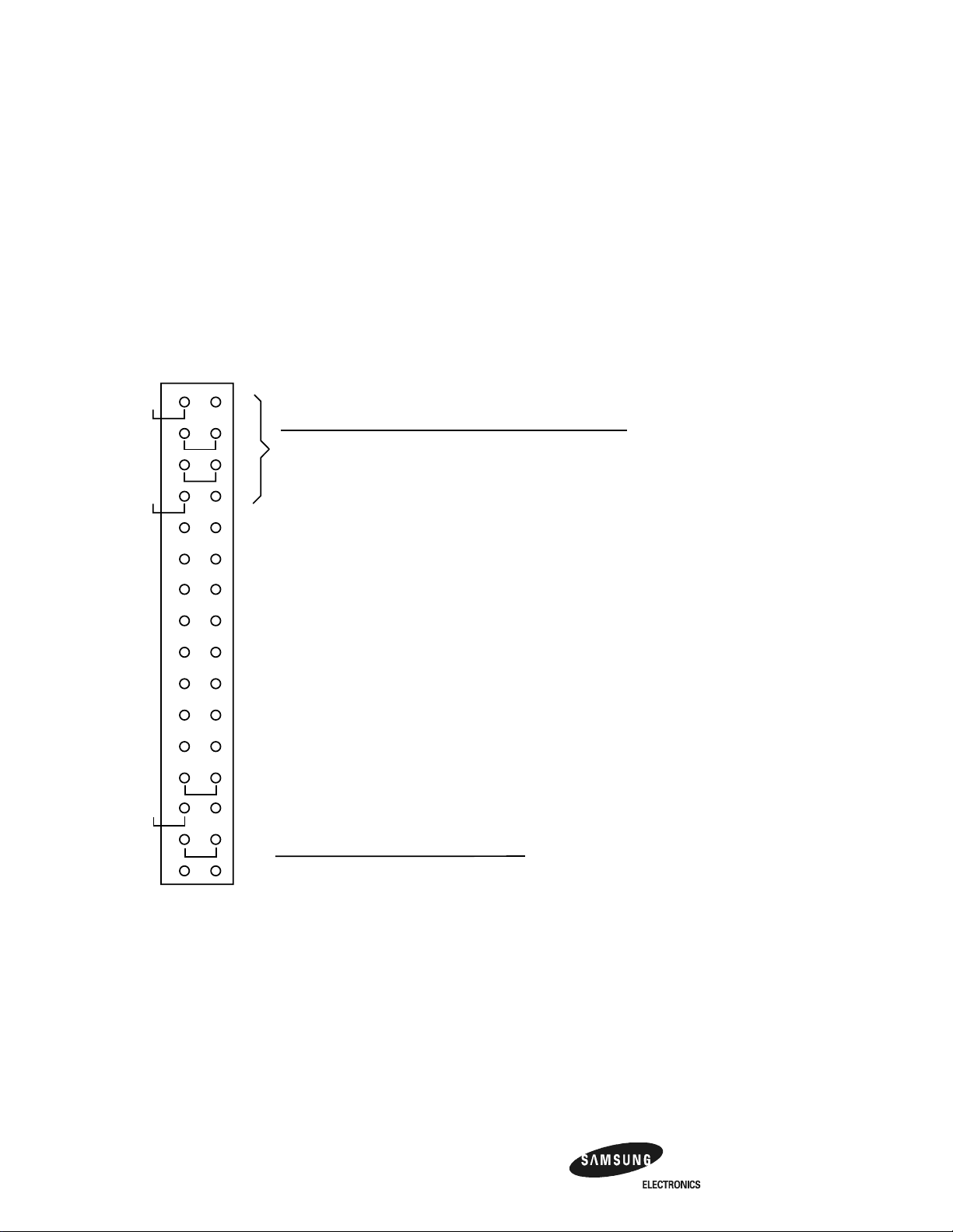
CPU Speed Selection (Option 1,2,3, &4)
)
Figure 3–1 AlphaPC 164UX Configuration Jumpers
J28 System Configuration Jumpers
Option 1
Option 2
Option 3
Option 4
Option 5
Option 6
Option 7
Option 8
Option 9
Option 10
Option 11
Option 12
Option 13
Option 14
Option 15
Option 16
Frequency
300 MHz In In In In
333 MHz
366 MHz
400 MHz Out Out In In
433 MHz
466 MHz
500 MHz In Out Out In
533 MHz
566 MHz
600 MHz Out In In Out
633 MHz
666 MHz
700 MHz In In Out Out
733 MHz
766 MHz
800 MHz Out Out Out Out
Option 5 : Pyxis Bus Speed Select(Default Out)
Option 6 : Reserved Default Out
Option 7 : Enable SROM Debug Mode(Default Out)
Option 8 : Enable Firmware Debug Mode(Default Out)
Option 9 : Enable only 1 set of Scache(Default Out)
Option 10 : Reserved Default Out
Option 11 : Boot SAFE ARCSBIOS Image(Default Out)
Option 12 : Reserved Default Out
Option 13 : Must be In
Bcache Size
0MB
1MB
2MB
4MB
Option1 Option2 Option3 Option4
Out
In
In
Out
Out
In
In
Out
Out
In
Option14 Option15
In
In
Out
Out
In In In
Out In In
In Out In
In Out In
Out Out In
In In Out
Out In Out
Out In Out
In Out Out
Out Out Out
Out
In
Out
In
Option 16 : FAN OK Signal Do not ever populate(Default Out
3.1 CPU Speed Selection (Option 1,2,3, &4)
The clock synthesizer makes it possible to change the frequency of the microproces-
sor’s clock input without having to change the clock crystal. Simply set the speed
jumpers to adjust the fre quency of the micro proces sor’ s cl ock. Thes e speed jumpe rs
are located at J2 8-1/2 (Opt ion 1), J28-3/4 ( Option 2), J28-5 /6 (Optio n 3), and J28-7/8
(Option 4). These four jumpers set speed at power-up as listed in Figure 3–1.
3–2 AlphaPC 164UX Jumper Configuration
Page 20

Bcache Size Jumpers (Option 14,15)
3.2 Bcache Size Jumpers (Option 14,15)
The Bcache size jumpers are located at J28–27/28 (Option14) and J28–29/30
(Option15), as shown in Figure 3–1. The AlphaPC 164UX-2/-4 is configured with
2MB/4MB of Bcache during production ; the other jumpers shown in Figure 3–1
(0,1) are for other implementations.
Note: The standard motherboard is manufactured with 128K X 18 or 256K X
18 data SSRAMs.
3.3 Boot Option Jumper (Option 11)
The boot option jumper is located at J28-21/22 (Option 11). The default position for
this jumper is out (Figure 3–1). This jumper sel ects the image to be loaded into memory from the system flash ROM. With the jumper out the ARCSBIOS firmware is
loaded. With the jumpe r in, the Safe ARCSBIOS is loaded.
AlphaPC 164UX Jumper Configura t ion 3–3
Page 21

AlphaPC 164UX Connector Pinouts
This section lists the pinouts of all AlphaPC 164UX connectors. See Figure 2–1 for
connector locations.
4.1 PCI Bus Connector Pinouts
Table 4–1 shows the PCI bus connector pinouts.
4
Table 4–1 PCI Bus Connector Pinouts
Pin Signal Pin Signal Pin Signal Pin Signal
32-Bit and 64-Bit PCI Connectors (J2, J5, J6, J7, J21, J22)
A1 TRST# A2 +12V A3 TMS A4 TDI
A5 Vdd A6 INTA A7 INTC A8 Vdd
A9 — A10 Vdd A11 — A12 Gnd
A13 Gnd A14 — A15 RST# A16 Vdd
A17 GNT# A18 Gnd A19 — A20 AD<30>
A21 +3V A22 AD<28> A23 AD<26> A24 Gnd
A25 AD<24> A26 IDSEL A27 +3V A28 AD<22>
A29 AD<20> A30 Gnd A31 AD<18> A32 AD<16>
A33 +3V A34 FRAME# A35 Gnd A36 TRDY#
A37 STOP# A38 STOP# A39 +3V A40 SDONE
A41 SBO# A42 Gnd A43 PAR A44 AD<15>
A45 +3V A46 AD<13> A47 AD<11> A48 Gnd
A49 AD<09> A50 Not used A51 Not used A52 C/BE#<0>
A53 +3V A54 AD<06> A55 AD<04> A56 Gnd
A57 AD<02> A58 AD<00> A59 Vdd A60 REQ64#
A61 Vdd A62 Vdd B1 –12V B2 TCK
B3 Gnd B4 TDO B5 Vdd B6 Vdd
B7 INTB B8 INTD B9 PRSNT1# B10 —
(Sheet 1 of 2)
AlphaPC 164UX Connector Pinouts 4–1
Page 22

PCI Bus Connector Pinouts
Table 4–1 PCI Bus Connector Pinouts
Pin Signal Pin Signal Pin Signal Pin Signal
(Sheet 2 of 2)
B11 PRSNT2# B12 Gnd B13 Gnd B14 —
B15 Gnd B16 CLK B17 Gnd B18 REQ#
B19 Vdd B20 AD<31> B21 AD<29> B22 Gnd
B23 AD<27> B24 AD<25> B25 +3V B26 C/BE#<3>
B27 AD<23> B28 Gnd B29 AD<21> B30 AD<19>
B31 +3V B32 AD<17> B33 C/BE#<2> B34 Gnd
B35 IRDY# B36 +3V B37 DEVSEL# B38 Gnd
B39 LOCK# B40 PERR# B41 +3V B42 SERR#
B43 +3V B44 C/BE#<1> B45 AD<14> B46 Gnd
B47 AD<12> B48 AD<10> B49 Gnd B50 Not used
B51 Not used B52 AD<08> B53 AD<07> B54 +3V
B55 AD<05> B56 AD<03> B57 Gnd B58 AD<01>
B59 Vdd B60 ACK64# B61 Vdd B62 Vdd
64-Bit PCI Connectors Only (J2)
A63 Gnd A64 C/BE#<7> A65 C/BE#<5> A66 Vdd
A67 PAR64 A68 D<62> A69 Gnd A70 D<60>
A71 D<58> A72 Gnd A73 D<56> A74 D<54>
A75 Vdd A76 D<52> A77 D<50> A78 Gnd
A79 D<48> A80 D<46> A81 Gnd A82 D<44>
A83 D<42> A84 Vdd A85 D<40> A86 D<38>
A87 Gnd A88 D<36> A89 D<34> A90 Gnd
A91 D<32> A92 — A93 Gnd A94 —
B63 — B64 Gnd B65 C/BE#<6> B66 C/BE#<4>
B67 Gnd B68 D<63> B69 D<61> B70 Vdd
B71 D<59> B72 D<57> B73 Gnd B74 D<55>
B75 D<53> B76 Gnd B77 D<51> B78 D<49>
B79 Vdd B80 D<47> B81 D<45> B82 Gnd
B83 D<43> B84 D<41> B85 Gnd B86 D<39>
B87 D<37> B88 Vdd B89 D<35> B90 D<33>
B91 Gnd B92 — B93 — B94 Gnd
4–2 AlphaPC 164UX Connector Pinouts
Page 23

ISA Expansion Bus Connector Pinouts
4.2 ISA Expansion Bus Connector Pinouts
Table 4–2 shows the ISA expansion bus connector pinouts.
Table 4–2 ISA Expansion Bus Connector Pinouts (J10)
Pin Signal Pin Signal Pin Signal Pin Signal
1 Gnd 2 IOCHCK# 3 RSTDRV 4 SD7
5Vdd 6SD6 7IRQ9 8SD5
9–5V 10 SD4 11 DRQ2 12 SD3
13 –12V 14 SD2 15 ZEROWS# 16 SD1
17 +12V 18 SD0 19 Gnd 20 IOCHRDY
21 SMEMW# 22 AEN 23 SMEMR# 24 SA19
25 IOW# 26 SA18 27 IOR# 28 SA17
29 DACK3# 30 SA16 31 DRQ3 32 SA15
33 DACK1# 34 SA14 35 DRQ1 36 SA13
37 REFRESH# 38 SA12 39 SYSCLK 40 SA11
41 IRQ7 42 SA10 43 IRQ6 44 SA9
45 IRQ5 46 SA8 47 IRQ4 48 SA7
49 IRQ3 50 SA6 51 DACK2# 52 SA5
53 TC 54 SA4 55 BALE 56 SA3
57 Vdd 58 SA2 59 OSC 60 SA1
61 Gnd 62 SA0 63 MEMCS16# 64 SBHE#
65 IOCS16# 66 LA23 67 IRQ10 68 LA22
69 IRQ11 70 LA21 71 IRQ12 72 LA20
73 IRQ15 74 LA19 75 IRQ14 76 LA18
77 DACK0# 78 LA17 79 DRQ0 80 MEMR#
81 DACK5# 82 MEMW# 83 DRQ5 84 SD8
85 DACK6# 86 SD9 87 DRQ6 88 SD10
89 DACK7# 90 SD11 91 DRQ7 92 SD12
93 Vdd 94 SD13 95 MASTER# 96 SD14
97 Gnd 98 SD15 — — — —
AlphaPC 164UX Connector Pinouts 4–3
Page 24

SDRAM DIMM Connector Pinouts
4.3 SDRAM DIMM Connector Pinouts
Table 4–3 shows the SDRAM DIMM connector pinouts.
Table 4–3 SDRAM DIMM Connector Pinouts (U3 through U8)1
Pin Signal Pin Signal Pin Signal Pin Signal
1 Gnd 2 DQ0 3 DQ1 4 DQ2
5 DQ3 6 3.3V 7 DQ4 8 DQ5
9 DQ6 10 DQ7 11 DQ8 12 Gnd
13 DQ9 14 DQ10 15 DQ11 16 DQ12
17 DQ13 18 3.3V 19 DQ14 20 DQ15
21 CB0 22 CB1 23 Gnd 24 NC
25 NC 26 3.3V 27 WE 28 DQMB0
29 DQMB1 30 S0 31 NC 32 Gnd
33 A0 34 A2 35 A4 36 A6
37 A8 38 A10 39 A12 40 3.3V
41 3.3V 42 CK0 43 Gnd 44 NC
45 S2 46 DQMB2 47 DQMB3 48 NC
49 3.3V 50 NC 51 NC 52 CB2
53 CB3 54 Gnd 55 DQ16 56 DQ17
57 DQ18 58 DQ19 59 3.3V 60 DQ20
61 NC 62 NC 63 CKE1 64 Gnd
65 DQ21 66 DQ22 67 DQ23 68 Gnd
69 DQ24 70 DQ25 71 DQ26 72 DQ27
73 3.3V 74 DQ28 75 DQ29 76 DQ30
77 DQ31 78 Gnd 79 CK2 80 NC
81 NC 82 SDA 83 SCL 84 3.3V
85 Gnd 86 DQ32 87 DQ33 88 DQ34
89 DQ35 90 3.3V 91 DQ36 92 DQ37
93 DQ38 94 DQ39 95 DQ40 96 Gnd
97 DQ41 98 DQ42 99 DQ43 100 DQ44
101 DQ45 102 3.3V 103 DQ46 104 DQ47
105 CB4 106 CB5 107 Gnd 108 NC
109 NC 1 10 3.3V 111 CAS 112 DQMB4
113 DQMB5 114 S1 115 RAS 116 Gnd
117 A1 118 A3 119 A5 120 A7
121 A9 122 BA0 123 A13 124 3.3V
(Sheet 1 of 2)
4–4 AlphaPC 164UX Connector Pinouts
Page 25

EIDE Drive Bus Connector Pinouts
1
Table 4–3 SDRAM DIMM Connector Pinouts (U3 through U8)
Pin Signal Pin Signal Pin Signal Pin Signal
125 CK1 126 BA1
2
127 Gnd 128 CKE0
129 S3 130 DQMB6 131 DQMB7 132 PD
3
133 3.3V 134 NC 135 NC 136 CB6
137 CB7 138 Gnd 139 DQ48 140 DQ49
141 DQ50 142 DQ51 143 3.3V 144 DQ52
145 NC 146 NC 147 PD 148 Gnd
149 DQ53 150 DQ54 151 DQ55 152 Gnd
153 DQ56 154 DQ57 155 DQ58 156 DQ59
157 3.3V 158 DQ60 159 DQ61 160 DQ62
161 DQ63 162 Gnd 163 CK3 164 NC
165 SA0 166 SA1 167 SA2 168 3.3V
1
Pins 1 through 84 are on the front side and pins 85 through 168 are on the back side.
2
The AlphaPC 164UX uses BA1 as both BA1 and ADDR12. Therefore, fo ur-bank DIMMs us in g
ADDR<11:0> ar e the maximum siz e. (Tw o-bank DIMMs ca n use ADDR<12:0>.)
3
Pull-down.
4.4 EIDE Drive Bus Connector Pinouts
(Sheet 2 of 2)
Table 4–4 shows the EIDE drive bus connector pinouts.
Table 4–4 EIDE Drive Bus Connector Pinouts (J24)
Pin Signal Pin Signal Pin Signal Pin Signal
1 RESET 2 Gnd 3 IDE_D7 4 IDE_D8
5 IDE_D6 6 IDE_D9 7 IDE_D5 8 IDE_D10
9 IDE_D4 10 IDE_D11 11 IDE_D3 12 IDE_D12
13 IDE_D2 14 IDE_D13 15 IDE_D1 16 IDE_D14
17 IDE_D0 18 IDE_D15 19 Gnd 20 NC (key pin)
21 MARQ 22 Gnd 23 IOW 24 Gnd
25 IOR 26 Gnd 27 CHRDY 28 BALE
29 MACK 30 Gnd 31 IRQ 32 IOCS16
33 ADDR1 34 NC 35 ADDR0 36 ADDR2
37 CS0 38 CS1 39 ACT 40 Gnd
AlphaPC 164UX Connector Pinouts 4–5
Page 26

Diskette Drive Bus Connector Pinouts
4.5 Diskette Drive Bus Connector Pinouts
Table 4–5 shows the diskette (floppy) drive bus connector pinouts.
Table 4–5 Diskette (Floppy) Drive Bus Connector Pinouts (J33)
Pin Signal Pin Signal Pin Signal Pin Signal
1 Gnd 2 DEN0 3 Gnd 4 NC
5 Gnd 6 DEN1 7 Gnd 8 INDEX
9 Gnd 10 MTR0 11 Gnd 12 DR1
13 Gnd 14 DR0 15 Gnd 16 MTR1
17 Gnd 18 DIR 19 Gnd 20 STEP
21 Gnd 22 WDATA 23 Gnd 24 WGATE
25 Gnd 26 TRK0 27 Gnd 28 WRTPRT
29 ID0 30 RDATA 31 Gnd 32 HDSEL
33 ID1 34 DSKCHG —— — —
4.6 Parallel Bus Connector Pinouts
Table 4–6 shows the parallel bus connector pinouts.
Table 4–6 Parallel Bus Connector Pinouts (J13)
Pin Signal Pin Signal Pin Signal Pin Signal
1 STB 2 PD0 3 PD1 4 PD2
5 PD3 6 PD4 7 PD5 8 PD6
9 PD7 10 ACK 11 BUSY 12 PE
13 SLCT 14 AFD 15 ERR 16 INIT
17 SLIN 18 Gnd 19 Gnd 20 Gnd
21 Gnd 22 Gnd 23 Gnd 24 Gnd
25 Gnd —— —— — —
4–6 AlphaPC 164UX Connector Pinouts
Page 27

COM1/COM2 Serial Line Connector Pinouts
4.7 COM1/COM2 Serial Line Connector Pinouts
Table 4–7 shows the COM1/COM2 serial line connector pinouts.
Table 4–7 COM1/COM2 Serial Line Connector Pinouts (J12)
COM1 Pin
(Top) COM1 Signal
1DCD1 1DCD2
2RxD1 2RxD2
3TxD1 3TxD2
4DTR1 4DTR2
5SG1 5SG2
6DSR1 6DSR2
7RTS1 7RTS2
8CTS1 8CTS2
9RI1 9 RI2
COM2 Pin
(Bottom) COM2 Signal
4.8 Keyboard/Mouse Connector Pinouts
Table 4–8 shows the keyboard/mouse connector pinouts.
Table 4–8 Keyboard/Mouse Connector Pinouts (J25)
Keyboard Pin
(Bottom) Keyboard Signal
1KBDATA 1MSDATA
2NC 2NC
3Gnd 3Gnd
4Vdd 4Vdd
5 KBCLK 5 MSCLK
6NC 6NC
Mouse Pin
(Top) Mouse Signal
AlphaPC 164UX Connector Pinouts 4–7
Page 28

Input Power Connector Pinouts
4.9 Input Power Connector Pinouts
Table 4–9 shows the input power connector pinouts.
Table 4–9 Input Power Connector Pinouts (J18)
Pin Voltage Pin Voltage Pin Voltage Pin Voltage
1 +3.3 V dc 2 +3.3 V dc 3 Gnd 4 +5 V dc
5 Gnd 6 +5 V dc 7 Gnd 8 P_DCOK
9 5 V SB 10 +12 V dc 11 +3.3 V dc 12 –12 V dc
13 Gnd 14 PS_ON 15 Gnd 16 Gnd
17 Gnd 18 –5 V dc 19 +5 V dc 20 +5 V d c
1
This pinout is ATX-compliant.
1
4.10 Narrow SCSI Bus Connector (UX only)
Table 4–10 shows the narrow SCSI bus connector pinouts
Table 4–10 Narrow SCSI Bus Connector (J16)
Pin Signal Pin Signal Pin Signal Pin Signal
1 GND 2 SD0 3 GND 4 SD1
5 GND 6 SD2 7 GND 8 SD3
9 GND 10 SD4 11 GND 12 SD5
13 GND 14 SD6 15 GND 16 SD7
17 GND 18 SDPO 19 GND 20 GND
21 GND 22 BUS_PRES 23 GND 24 GND
25 NC 26 TERMPWR 27 GND 28 GND
29 GND 30 GND 31 GND 32 SATN
33 GND 34 GND 35 GND 36 SBSY
37 GND 38 SACK 39 GND 40 SRST
41 GND 42 SMSG 43 GND 44 SSEL
45 GND 46 SCD 47 GND 48 SREQ
49 GND 50 SIO
4–8 AlphaPC 164UX Connector Pinouts
Page 29

Fast and Wide SCSI Bus Connector (UX only)
4.11 Fast and Wide SCSI Bus Connector (UX only)
Table 4–11 shows the Fast and Wide SCSI bus connector pinouts
Table 4–11 Fast and Wide SCSI Bus Connector Pinouts (J15)
Pin Signal Pin Signal Pin Signal Pin Signal
1 GND 2 GND 3 GND 4 GND
5 GND 6 GND 7 GND 8 GND
9 GND 10 GND 11 GND 12 GND
13 GND 14 GND 15 GND 16 GND
17 TERMPWR1 18 TERMPWR1 19 NC 20 GND
21 GND 22 GND 23 GND 24 GND
25 GND 26 GND 27 GND 28 GND
29 GND 30 GND 31 GND 32 GND
33 GND 34 GND 35 SD12
37 SD14 38 SD15 39 SDP1 40 SD0
41 SD1 42 SD2 43 SD3 44 SD4
45 SD5 46 SD6 47 SD7 48 SDP0
49 GND 50 BUS_PRES 51 TERMPWR1 52 TERMPWR1
53 NC 54 GND 55 SA TN
57 SBSY
61 SSEL 62 SCD 63 SREQ 64 SIO
65 SD8 66 SD9 67 SD10 68 SD11
69 GND 70 GND
58 SACK 59 SRST 60 SMSG
36 SD13
56 GND
4.12 10/100 Mbit Ethernet Connector Pinouts (UX only)
Table 4–12 shows the 10/100 Mbit Ethernet connector pinouts
Table 4–12 10/100 Mbit Ethernet Connector Pinouts (J34)
Pin Signal Pin Signal Pin Signal Pin Signal
1 TD_P 2 TD_M 3 RD_P 4 U1
5U2 6RD_M 7U3 8U4
9MP1 10MP2
AlphaPC 164UX Connector Pinouts 4–9
Page 30

Speaker Connector Pinouts
4.13 Speaker Connector Pinouts
Table 4–13 shows the speaker connector pinouts.
Table 4–13 Speaker Connector Pinouts (J23)
Pin Signal Name
1 SPKR Speaker output
2NC —
3 VDD —
4 GND —
4.14 Microprocessor Fan Power Connector Pinouts
Table 4–14 shows the microprocessor fan power connector pinouts.
Table 4–14 Microprocessor Fan Power Connector Pinouts (J35)
Pin Signal Name
1+12V —
2 FAN_OK_L Fan connected
3 GND —
4.15 Pin Power LED Connector Pinouts
Table 4–15 shows the power LED connector pinouts.
Table 4–15 Power LED Connector Pinouts (J31)
Pin Signal Name
1 Powerpullup Power pullup
2NC —
3 GND —
4NC —
5NC —
4–10 AlphaPC 164UX Connector Pinouts
Page 31

IDE Drive LED Connector Pinouts
4.16 IDE Drive LED Connector Pinouts
Table 4–16 shows the IDE drive LED connector pinouts.
Table 4–16 IDE Drive LED Connector Pinouts (J29)
Pin Signal Name
1 ACTIVITY Hard drive active
2 ACTIVUTYPULLUP
4.17 Reset Switch Connector Pinouts
Table 4–17 shows the reset switch connector pinouts.
Table 4–17 Reset Switch Connector Pinouts (J37)
Pin Signal Name
1 GND —
2 RSTSWITCH Reset system
4.18 Soft Power Switch Connector Pinouts
Table 4–18 shows the soft power switch connector pinouts.
Table 4–18 Soft Power Switch Connector Pinouts (J36)
Pin Signal Name
1 GND —
2 PWRSWITCH System power on/off
4.19 SCSI LED Connector Pinouts
Table 4–19 shows the SCSI LED connector pinouts.
Table 4–19 SCSI LED Connector Pinouts (J17)
Pin Signal Name
1 SCSI_BUSY —
2 SCSI_BSY2 —
AlphaPC 164UX Connector Pinouts 4–1 1
Page 32

Memory and Microprocessor Configuration
For higher system speed or greater throughput, you can upgrade SDRAM memory
by replacing DIMMs with those of greater size.
When configuring or upgrading SDRAM, observe the following rules:
• Each DIMM must be a 168-bit unbuffered version and have a frequency of
100 MHz.
• All DIMMs must be of equal size if they are in the same bank.
5.1 Configuring SDRAM Memory
Although not an exhaustive list, Ta ble 5–1 lists the tested SDRAM memory
configurations avail abl e.
For a list of vendors who supply components and accessories for the AlphaPC
164UX, see Appendix A.
Refer to Figure 2–1 for DIMM connector loc ations.
5
Table 5–1 AlphaPC 164UX SDRAM Memory Configurations
Total
Memory
32MB 16MB 16MB
64MB 16MB 16MB 16MB 16MB
96MB 16MB 16MB 16MB 16MB 16MB 16MB
Bank 0 Bank 1 Bank 2
U3 U4 U5 U6 U7 U8
32MB 32MB
32MB 32MB 16MB 16MB
Memory and Microprocessor Configuration 5–1
Page 33

Configuring SDRAM Memory
Table 5–1 AlphaPC 164UX SDRAM Memory Configurations
Total
Memory
128MB 32MB 32MB 16MB 16MB 16MB 16MB
160MB 32MB 32MB 32MB 32MB 16MB 16MB
192MB 32MB 32MB 32MB 32MB 32MB 32MB
192MB 64MB 64MB 32MB 32MB
224MB 64MB 64MB 32MB 32MB 16MB 16MB
256MB 64MB 64MB 32MB 32MB 32MB 32MB
288MB 128MB 128MB 16MB 16MB
320MB 64MB 64MB 64MB 64MB 32MB 32MB
352MB 128MB 128MB 32MB 32MB 16MB 16MB
384MB 64MB 64MB 64MB 64MB 64MB 64MB
416MB 128MB 128MB 64MB 64MB 16MB 16MB
448MB 128MB 128MB 64MB 64MB 32MB 32MB
512MB 128MB 128MB 64MB 64MB 64MB 64MB
544MB 128MB 128MB 128MB 128MB 16MB 16MB
576MB 128MB 128MB 128MB 128MB 32MB 32MB
608MB 256MB 256MB 32MB 32MB 16MB 16MB
640MB 128MB 128MB 128MB 128MB 64MB 64MB
Bank 0 Bank 1 Bank 2
U3 U4 U5 U6 U7 U8
32MB 32MB 32MB 32MB
64MB 64MB
64MB 64MB 16MB 16MB
64MB 64MB 16MB 16MB
64MB 64MB 64MB 64MB
128MB 128MB
128MB 128MB 16MB 16MB 16MB 16MB
128MB 128MB 32MB 32MB
128MB 128MB 32MB 32MB 32MB 32MB
128MB 128MB 64MB 64MB
128MB 128MB 128MB 128MB
256MB 256MB
256MB 256MB 16MB 16MB
256MB 256MB 16MB 16MB 16MB 16MB
256MB 256MB 32MB 32MB
5–2 Memory and Microprocessor Configuration
Page 34

Upgrading SDRAM Memory
Table 5–1 AlphaPC 164UX SDRAM Memory Configurations
Total
Memory
672MB 256MB 256MB 64MB 64MB 16MB 16MB
704MB 256MB 256MB 64MB 64MB 32MB 32MB
768MB 128MB 128MB 128MB 128MB 128MB 128MB
800MB 256MB 256MB 128MB 128MB 16MB 16MB
832MB 256MB 256MB 128MB 128MB 32MB 32MB
896MB 256MB 256MB 128MB 128MB 64MB 64MB
1024MB 256MB 256MB 128MB 128MB 128MB 128MB
1056MB 256MB 256MB 256MB 256MB 16MB 16MB
1088MB 256MB 256MB 256MB 256MB 32MB 32MB
1152MB 256MB 256MB 256MB 256MB 64MB 64MB
1280MB 256MB 256MB 256MB 256MB 128MB 128MB
1536MB 256MB 256MB 256MB 256MB 256MB 256MB
Bank 0 Bank 1 Bank 2
U3 U4 U5 U6 U7 U8
256MB 256MB 32MB 32MB 32MB 32MB
256MB 256MB 64MB 64MB
256MB 256MB 64MB 64MB 64MB 64MB
256MB 256MB 128MB 128MB
256MB 256MB 256MB 256MB
Note: The following are important items to remember
- in order for the ECC memory feature to work, all DIMMs must be 72bit.
- To populate a bank,you must use 2 matched DIMMs.
5.2 Upgrading SDRAM Memory
You can upgrade memory in the AlphaPC 164UX by adding more DIMMs or
replacing the ones that you have with a greater size. Refer to Figure 2–1 for DIMM
connector locations.
Use the following general guidelines:
1. Observe antistatic precautions. Handle DIMMs only at the edges to prevent
damage.
2. Remove power from the system.
3. Open levers and align the DIMM.
Memory and Microprocessor Configuration 5–3
Page 35

Increasing Microprocessor Speed
4. Firmly push the module into the connector. Ensure that the DIMM snaps into the
plastic locking levers on both ends.
5. Restore power to the system.
5.3 Increasing Microprocessor Speed
This section describes how to complete the following actions to increase
microprocessor speed:
• Replace the 21 164 micropro cessor with an Al phaPC chip that ha s a higher speed
rating.
• Reconfigure the CPU speed selection jumpers (J28 Option 1~4).
5.3.1 Preparatory Information
Caution: Static-Sensitive Component – Due to the sensitive nature of electronic
components to static electricity, anyone handling the microprocessor
must wear a properly grounded antistatic wriststrap. Use of antistatic
mats, ESD approved workstations, or exercising other good ESD practices is recommended.
A 21164 microprocessor with a higher speed rating is available from your local
distributor. See Appendix A for information about supporting products.
When replacing the microprocessor chip, also replace the thermal conducting
GRAFOIL pad. See Appendix A for information about the parts kit, which includes
the heat sink, GRAFOIL pad, two hex nuts, heat-sink clips, 60-mm fan, fan guard,
and four screws.
5.3.2 Required Tools
The following tools are required when replacing the microprocessor chip:
A TS30 manual nut/torque driver (or equivalent) with the following attachments is
required to affix the heat sink and fan to the microprocessor’s IPGA package:
• 1/4-inch hex bit
• 7/16-inch socket with 1/4-inch hex drive
• #2 Phillips-head screwdriver bit
5–4 Memory and Microprocessor Configuration
Page 36

Increasing Microprocessor Speed
5.3.3 Removing the 21164 Microprocessor
Remove the microprocessor currently in place at location U55 by performing the
following steps:
1. Unplug the fan power/sensor cable from connector J35 (see Figure 2–1).
2. Remove the four 6-32
the heat sink.
3. Remove the fan and fan guard.
4. If the sink/chip/fan clip is us ed, remove it by unhoo king its end s from around t he
ZIF socket retainers.
5. Using a 7/16-inch socket, remove the two nuts securing the heat sink to the
microprocessor studs.
6. Remove the heat sink by gently lifting it off the microprocessor.
7. Remove and discard the GRAFOIL heat conduction pad.
8. Thoroughly clean the bottom surface of the heat sink before affixing it to the
new microprocessor.
9. Lift the ZIF socket actuator handle to a full 90° angle.
10. Remove the microprocessor chip by lifting it straight out of the socket.
X 0.875-inch screws that secure the fan and fan guard to
5.3.4 Installing the 21164 Microprocessor
Install the new microprocessor in location U55 by performing the following steps:
Note: Install the heat sink on ly after the mi cropro cessor has be en ass embled t o
the ZIF socket.
1. Observe antistatic precautions.
2. Lift the ZIF socket actuator handle to a full 90° angle.
3. Ensure that all the pins on the microprocessor package are straight.
4. The ZIF socket and microprocessor are keyed to allow for proper installation.
Align the microprocessor, with its missing AD01 pin, with the corresponding
plugged AD01 position on the ZIF socket. Gently lower into position.
5. Close the ZIF socket actuator handle to its locked position.
Memory and Microprocessor Configuration 5–5
Page 37

Increasing Microprocessor Speed
6. Install the heat sink and heat-sink fan as directed in the following steps. A heatsink/fan kit is avail able from t he vendor li sted at the begi nning of th is procedur e.
Refer to Figure 5–2 for heat-sink and fan assembly details.
Figure 5-1 shows the Fan/Heat-Sink Assembly on AlphaPC 164UX.
Figure 5–2 Fan/Heat-Sink Assembly
Screw, 6-32 x 0.875 in
Qty 4
Guard, Fan
Fan
Clip, Heat Sink/Chip/Fan
Nut, Hex, 1/4-20, 2011-T3
Aluminum, 0.438 in Across
Flats, Qty 2
Torque to 20 +/- 2 in-lbs
Heat Sink, with Fan
Mounting Holes
Airflow
a. Put the GRAFOIL thermal pad in place. The GRAFOIL pad is used to
improve the thermal conductivity between the chip package and the heat
sink by replacing micro air pockets with a less insulative material. Perform
the following steps to position the GRAFOIL pad:
1. Perform a visual inspection of the package slug to ensure that it is free of
contamination.
2. Wearing clean gloves, pick up the GRAFOIL pad. Do not perform this
with bare hands because skin oils can be transferred to the pad.
5–6 Memory and Microprocessor Configuration
Thermal Pad
Alpha 21164
Page 38

Increasing Microprocessor Speed
3. Place the GRAFOIL pad on the gold-plated slug surface and align it with
the threaded studs.
b. Attach the microprocessor heat sink. The heat-sink material is clear anod-
ized, hot-water-sealed, 6061-T6 aluminum. The nut material is 2011-T3 aluminum (this grade is critical). Perform the following steps to attach the heat
sink:
1. Observe antistatic precautions.
2. Align the heat-sink holes with the threaded studs on the ceramic package.
3. Handle the heat sink by the edges and lower it onto the chip package,
taking care not to damage the stud threads.
4. Set a calibrated torque driver to 20 in-lbs, ±2 in-lbs (2.3 Nm, ±0.2 Nm).
The torque driver should have a mounted 7/16-inch socket.
5. Insert a nut into the 7/16-inch socket, place on one of the studs, and
tighten to the specified torque. Repeat for the second nut.
6. If the sink/chip/fan clip is used, properly install it by positioning it over
the assembly and hooking its ends around the ZIF socket retainers.
c. Attach the heat-sink fan assembly:
1. Place the fan assembly on top of the heat sink, aligning the fan mounting
holes with the corresponding threaded heat-sink holes. Align the fan so
that the fan power/sensor wires exit the fan closest to connector J35 (see
Figure 2–1). Fan airflow must be directed into the heat sink (fan label
facing down toward the heat sink).
2. Place the fan guard on top of the fan. Orient the guard so that the corner
mounting areas lay flush against the heat sink.
3. Secure the fan and fan guard to the heat sink with four 6-32
X 0.875-inch
screws.
4. Plug the fan power/sensor cable in to connecto r J35.
Important: When installing the microprocessor, you must change the frequency of
its clock output by setting the CPU speed sele cti on jumpers (J28 Option
1~4), as described in Section 3.1.
Memory and Microprocessor Configuration 5–7
Page 39

This section lists the system and I/O interrupt assignments. It also lists the physical
Alpha 164UX I/O space assignments.
6.1 Interrupts
Table 6–1 lists each Alpha 164UX ISA interrupt and its source.
6
Interrupts and ISA Bus Addresses
Table 6–1 ISA Interrupts
Interrupt Number Interrupt Source
IRQ0 Internal timer
IRQ1 Keyboard
IRQ2 Interrupt from controller 2
IRQ3 COM2
IRQ4 COM1
IRQ5 Available
IRQ6 Diskette (floppy)
IRQ7 Parallel port
1
IRQ8#
IRQ9 Available
IRQ10 Available
IRQ11 Available
IRQ12 Mouse
Reserved
(Sheet 1 of 2)
Interrupts and ISA Bus Addresses 6–1
Page 40

ISA I/O Address Map
Table 6–1 ISA Interrupts
Interrupt Number Interrupt Source
IRQ13 Available
IRQ14 IDE
IRQ15 IDE
1
The # symbol indicates an active low signal.
6.2 ISA I/O Addre s s Map
Table 6–2 lists the Alpha 164UX ISA I/O space address mapping.
Table 6–2 ISA I/O Address Map
Range (hex) Usage
060-060 i8042 PRT
064-064 i8042 PRT
1F0-1F7 ATAPI
2F8-2FE Serial port—COM2
378-37B Parallel Port—LPT2
3F0-3F5 Floppy
(Sheet 2 of 2)
3F6-3F6 ATAPI
3F7-3F7 Floppy
3F8-3FE Serial port—COM1
6.2.1 Flash ROM Address Map
The flash ROM is mapped to thr ee regions of memory. Access to the first two
regions is RO. The first two regions provide the software necessary to initialize the
system and transfer execution to the next level of software. When power is turned
on, address ranges 0 to 00.00FF.FFFF and 0F.FC00.0000 to 0F.FFFF.FFFF are
enabled. After the s yst em has b een ini tial ized, these two add ress r anges are disa bled.
Byte mode is then enabled in the 21164 and 21174. Byte mode is the only way to
access the flash ROM in address range 87.C000.0000 to 87.FFFF.FFFF. 21164 byte
6–2 Interrupts and ISA Bus Addresses
Page 41

ISA I/O Address Map
instructions LDBU and STB must be used to access this region. Any other
instructio n will produc e UNDEFINED results with the possibility of damagi ng the
flash ROM.
Interrupts and ISA Bus Addresses 6–3
Page 42

Configuring for Windows NT
This chapter describes the ARCSBIOS and gives in struc tion to be gin the in stall atio n
of Windows NT.
7.1 ARCSBIOS
The AlphaPC 164UX motherboard ships with the ARCSBIOS firmware. This firmware initializes the system and enables you to boot the Windows NT operating system. The ARCSBIOS firmware resides in the flash ROM on the AlphaPC 164UX
motherboard.
7.1.1 Navigating the ARCSBIOS
Table 7–1 shows the keys used to navigate the ARCSBIOS and their function
Table 7–1 Navigation Keys
Press... To...
ENTER Select a highlighted option in a menu
or Move highlight within a menu.
or Cycle through available field values.
SPACE Cycle through available field values.
ESC Move up one level in the menu structure
7
7.1.2 Exploring the ARCSBIOS
The main screen of the ARCSBIOS is displayed when the motherboard is booted. It
displays information about the processor, memory, serial ports, parallel port, mouse,
and drives attached to the system. Figure 7–0 shows the main bios screen.
Configuring for Windows NT 7–1
Page 43

ARCSBIOS
Figure 7–1 Main Bios Screen
ARCSBios 1.3.060/SN 3010000,510026
(C) Copyright 1993-1998 Deskstation Technology
Boot Options
Windows NT Workstation 4.0
Enter Setup
CPU REV Primary Secondary External Total Free
Cache Cache Cache Memory Memory
21164A 5 8/8 KB 96KB 4096KB 131072KB 130008KB
ECC Mem : Yes
DIMM Size
Bank1 64/64
Bank 2 0/0
Bank 3 0/0
Adaptor ID Type Model Size
FDC0 A: Floppy 3 1/2" 1.44MB
SCSI0 6 DISK SAMSUNG WNR-32501S 020 2.41GB
SCSI0 7 HA Symbios 53C8XX SCSI Adapter
SCSI1 0 CDROM SAMSUNG SCR-2430 MS102 1.0 520MB
SCSI1 255 HA ATAPI IDE Controller
Serial Port IRQ
COM 1(0) 03F8 4
COM 2(0) 02F8 3
Parallel Port IRQ
LPT2(0) 0378 7
APC 164UX/BX
67MHz/600MHz
Mouse : PS/2(0)
The upper left hand corner of the s creen di splay s th e revis ion of th e ARCSBIOS and
the system serial number. The upper right hand corner of the screen displays the
speed that the AlphaPC 164UX i s runn ing. The fir st numbe r is th e c lock speed of t he
system bus. The seco nd number i s the clock speed o f the 21164 microprocessor . The
remaining section of the bios screen are discussed below.
a. Boot Options. The boot options section is the only interactive part of the main
bios screen. It al lows you t o selec t which NT install ation y ou would like to boot o r
it allows you to enter setup.
b. Processor Information. The next l ine disp lays information about the micr opr oce s-
sor. It also displays the sizes of the primary, secondary, and external caches. The
primary and secondary cac hes are bu ilt in to the Alpha 21164 microprocesso r. The
external cache is built onto the AlphaPC 164UX motherboard.
7–2 Configuring for Windows NT
Page 44

ARCSBIOS Setup.
c. Memory Information. The Total Memory section displays the total amount of
memory in the system in Kilobytes. The Free Memory section displays the
amount of memory available to the operating system. The ECC Mem indicator
tells if the memory in the system allows the system to use error correcting codes.
The DIMM table shows what banks are populated with DIMMS and what size
they are.
d. I/O Section. The serial port section show what serial ports were detected in the
system. The Mouse section shows the type of mouse that was detected on the system. The type of mouse to be detected is set in the Set Device Option portion of
Advanced Setup (see Section 7.2.3). The Parallel section shows the parallel port
that is detected on the system. The IRQ of the parallel port can be set in the Set
Device Options section of Advanced Setup (see Section 7.2.3).
e. The Drive Section. The drive sec tion di splays the fl oppy dri ves, IDE devi ces, an d
SCSI devices attached to the motherboard. In Figure 7–0 the type section is left
blank for th e hard drive and CD-ROM drive. In a real system the manufacturer
and model of the drives would be displayed.
7.2 ARCSBIOS Setup.
If you choose the enter setup option on the main scr een, you will be taken to another
screen with the setup menu in the foregr ound and the system configu ration tree in th e
background. The following selections are listed on the menu: Run a Program, Environment Variables, Set Time & Date, System Configuration, Print Configuration,
and Add-in Board Utilities.
7.2.1 Run a Program
Selecting the Run a Program option will bring up a window that says Enter full path
of program to run -->. This allows you to run programs from floppy, hard disk, or
CD-ROM drive. This option is used to begin the installation of Windows NT or to
run a system configuratio n utility. The path is composed of the drive letter (use CD
for the CD-ROM drive) followed by a colon and a backslash and the name of the
directory it is in, if any, followed by a back slash and the file name.
7.2.2 Environment Variables
The environment variab les te ll the syste m where to l ook to bo ot Windows NT. They
are created when Windows NT is installed. They should not be changed under nor-
mal circumstances.
Configuring for Windows NT 7–3
Page 45

ARCSBIOS Setup.
Caution : Changing the environment variables may cause Windows NT to fail to
boot.
There are 4 selections on the Environment Variable menu. Edit Environment Vari-
able Set allows you to change an existing environment variable set. Select Default
Environment Variable Set allows you to select whi ch bo ot s election will boot auto-
matically if the autoload feature is enabled. Create Environment Variable Set
allows you to create a new environment variable set. You will be prompted to enter
the system partition, the OS partition, and then select the version of Windows NT
you are trying to boot. Delete Environment Variable Set allows you to delete an
existing en vironment variable set.
7.2.3 Advanced Setup
This option brings up a submenu with 6 options. These options are described below.
a. Display Disk Resources. This option displays the drive section of the main
ARCSBIOS screen.
b. Display Device Resources. This option brings up a menu that allows you to
decide which device resources you wish to view. The following options are available: Interrupt Resources, DMA Channel, I/O Port Resources, and Memory
Resources.
c. Set NVRAM Options. This opti on brings up another menu wit h t h re e s el ect io ns.
These selections are described below.
1. Set Device Options. This selection brings up a screen that allows you to set the
following options. Floppy Drive 0 is used set the size of the first floppy drive
installed in the system. Fl oppy Drive 1 is us ed t o set the si ze of the seco nd fl opp y
drive installed in the system. The default is for Floppy Drive 0 to be set to 1.44M
3 1/2" Drive and Floppy Drive 1 to be set to Not Installed. The next section
allows you to set the interrupt level of the parallel port. The default is for LPT1
and LPT 3 to be set to Not installed and LPT 2 to be set to IRQ 7. The Pointing
Device setting allows you to set the type of pointing device the system tries to
detect. The default is Autodetect. The next 3 setting give you the option of
enabling or disabling the onboard Network, SCSI, and IDE controllers. The
default for all of these is Yes to enable them. Load Embedded SCSI Drivers
should be set to Yes. This loads the SCSI drivers built into the ARCSBIOS. Load
Soft SCSI Drivers and Enable SCSI Delays should both be set to No. The Enabl e
IDE Hard Drive Driver option is set defau lt to No. This option should only be set
to Yes if you are using an old IDE drive tha t does not work wit h the ATAPI driver.
7–4 Configuring for Windows NT
Page 46

ARCSBIOS Setup.
The option to Enable X8 6 Emulation is set default to Yes. This option allows an
operating system to use the X86 emulato r built into the ARCSBIOS t o emulate the
video BIOS built into most video adapters. The DIMM Bank Memory type settings can allow you t o get a p erformance increas e if you know the man ufacture r of
the SDRAM chips on your DIMMs. If the Manufacturer is NEC, or Toshiba use
the setting for t hem. I f the re it is an oth er ma nufact urer use ei th er the Other Mode
or the Safe Mode. If you don’t know the SDRAM manufacturer t hen use th e Safe
Mode.
2. SCSI Miniport Order. This section allows you to set the order in which SCSI
and ATAPI devices are detected. The default settings are as follows:
Symbios 53C8xx SCSI Adapter: 0
ATAPI IDE Controller : 1
<Empty SCSI Miniport Driver Slot> : Disabled
3. Configure PCI devices. This section should not be used. The ARCSBIOS will
automatically configure PCI devices.
d. Upgrade Firmware. The section allows you to upgrade the ARCSBIOS firm-
ware (see Section 7.3).
e. Show Firmware Revision. This option displays the revision of the ARCSBIOS
firmware and shows if it is a valid image or not.
7.2.4 System Time and Date
The option allows you to set the time and date for the real time clock. Times should
be entered in military time. Press the ENTER key after typing in each entry. Press
ESC to exit the section.
7.2.5 System Configuration
This option allows you to look at the system configuration tree. You can move
around the tree by using th e arrow keys . If you move the highlight to a disk an d press
ENTER, you will be given a menu of options. The first option is Configure Com-
ponent. This option should not be used. The next option is Directory. With this
option you will be prompted to select which partition’s directory you wish to see.
Note: The ARCSBIOS cannot read the NTFS file system. It can only give
directories of FAT partitions.
The third option is Copy Files. When this is selected you will be prompted to enter
the path of the source file, then the path of the de stination file. The file will then be
copied.
Configuring for Windows NT 7–5
Page 47

Upgrading the ARCSBIOS Firmware.
7.2.6 Print Configuration
This option will dump the information in the configuration tree to the parallel port so
that it may be printed.
7.2.7 Add-in Board Utilities
This option allows you to run configuration utilities for add-in cards that have been
ported to the AlphaPC 164UX motherboard. At the time of printing there are no utilities available.
7.3 Upgrading the ARCSBIOS Firmware.
To upgrade the ARCSBIOS firmware, you will need to have an ARCSBIOS Firmware Upgrade floppy. To upgrade the firmware follow the following steps.
1. Insert the Firmware Upgrade for AlphaPC 164UX disket te int o the fl oppy driv e.
2. Get the moth erboard to the b ios level.
3. From the main ARCSBIOS screen select Enter Setup.
4. From the Setup Menu, select Advanced Setup.
5. From the Advanced Setup Menu, select Upgrade Firmware.
6. Press ENTER to begin the upgrade.
7.4 Installing Windows NT
This section supplements the Micr osoft W i ndows NT insta llation guide for in stalling
Windows NT on a AlphaPC 164UX system.
7.4.1 Requirements
You need the follo wing hardware and software to install the Windows NT operating
system on a AlphaPC 164UX system:
• A 100MB or larger hard drive
• 32 MB or more of memory
• The Microsoft Windows NT compact disk
• The Install Floppy for Windows NT 4.0 for AlphaPC 164UX diskette
Note: The Install Floppy for Windows NT 4.0 for AlphaPC 164UX diskette is
required for W i ndows NT 4.0 op erating s ystem. Future v ersions may not
require diskette. Contact your OEM or system vendor for details.
7–6 Configuring for Windows NT
Page 48

7.4.2 Before Installing Windows NT
Before installing Windows NT, ensure that you have completed the following tasks:
• In the Setup sect ion of t he bios use the T ime and Date optio n to veri fy the c orrec t
time and date. (see Section 7.2.4).
Note: Some programs look at the dates on all files on the system to determine
if their lice nse i s expired or not. I f the date and ti m e a re not set correctly
before installation some programs may not run.
• Determine the type o f drives installed in your sy stem. You can do this by looki ng
at the main ARCSBIOS screen. In the drive section, in the adapter column you
will see a list of the S C SI bu sse s. Not e what SCSI bus your hard drives a nd CDROM drive are on. Next locate the host adapter entry for each bus. They have
HA in the type column. Read the description in the model column. This will tell
you whether the drives on that bus are IDE or SCSI.
• Use the Arcinstall utility to create a system partition. Follow the steps below:
1. Insert the Windows NT CD into the CD-ROM drive.
2. From the main ARCSBIOS screen select Enter Setup.
3. Select Run a Program from the setup menu.
4. Type in: CD:\alpha\arcinst.exe
5. Press ENTER
6. The Arci nstall Utility will start. In the menu shown select C onfigure Partitions
and press ENTER.
7. On the next menu that comes up select Create System Partition and press
ENTER.
8. If you have more than one har d drive, yo u will be as ked to sel ect the har d drive on
which you wish to create the system partition. Select the appropriate drive and
press ENTER.
9. You will be prompted to enter the si ze in MB of the pa rtition . Type in 10 and press
ENTER.
10. The system will format the par tition. When it is finish ed you will be prompt ed to
press any key to continue. Press a key.
11. Select Exit on the menu that comes up and press ENTER.
12. Select Exit on the next menu and press ENTER.
Installing Windows NT
• If you want to install Windows NT using with other SCSI device (or on
BX),Follow the steps below:
Configuring for Windows NT 7–7
Page 49

Installing Windows NT
1.Insert the Windows NT4.0 install Floppy for the AlphaPC 164UX diskette into
drive A:
2.From the main ARCSBIOS screen select Enter Setup.
3.select Run a Program from the setup menu and press Enter.
4.Type in: A:\miniport.exe and press Enter.
5.Maintain Flash Device will star t.In the Menu sh own sel ect Add SCSI Mini port t o
Flash and press Enter
6.Remove the W in dows NT4.0 install Floppy for t he Al pha PC 164UX diskette from
drive A:
7.Insert the disk labeled manufacturer supplied hardware support disk into drive A:
8.Type SCSI Driver File Name for SCSI card.
ex)Type A:\xxxx.sys and press Enter
9.The next screen disp layed will say what woule you like to call the Flash file?-->
press ENTER to accept : [xxxx.sys]
If you want to accept, press Enter
Please enter a description of the FLASH file-->
Type description and press Enter
ex) Adaptec
10.In Maintain Flash Device Menu select save changes to Flash and Exit and
Enter
11.If upgrade Firmware completed,press Enter
12.Restart your computer
13.From the main ARCSBIOS sereen select Enter Setup
14.In Advanced setup->Set NVRAM options->SCSI miniport order press Enter
15.In SCSI Miniport Detection Order Menu select Adaptec(description)
16.Change Disa b l e to 0 with <-- key and --> key.
17.press ESC Twice
18.In Save Configuration Menu displayed will say Save changes to Non-Volatile
RAM(Y/N)
19.Press Y and Enter.
20.if you restart your computer,your SCSI Device will be detected.
21.If you want to delete SCSI Device file,In Maintain Flash device Menu select
Delete SCSI Miniport from Flash
7.4.3 Windows NT Setup
Windows NT setu p, located on th e Microsoft W indows NT CD, installs th e W indows
NT operating system. Windows NT setup provides a brief description of the available key functions at the bottom of the screen.
7–8 Configuring for Windows NT
Page 50

Installing Windows NT
The following procedure supersedes the Starting Setup on a RISC-based computer
section of the Microsoft Windows NT Installation Guide.
To start the Windows NT Setup program:
1. Insert the Windows NT CD in the CD-ROM drive.
2. Restart your computer.
3. Select Enter Setup and Run a Program.
4. Type CD:\alpha\setupldr and press ENTER
The Windows NT Setup program will start. It will begin copying files to memory.
Setup will come up with the message: Setup could not determine the type of computer you have. There will be a list of computer types in a list box. Highlight the
Other option and press ENTER. You will be prompted to "Please insert the disk
labeled manufacturer supplied hardware support disk into drive A:. *Press enter
when ready *." Make sure that the Windows NT 4.0 Install Floppy for the Alpha PC
164UX diskette is in drive A: and press ENTER. A list box with APC 164UX
Alpha 56/xxx in it will be dis played. Press ENTER. Setup will begin copying files
again.
Note: The next steps depend on the type of drives that you have.
You must have determined if you have IDE , SCSI, or a combination of
drives.
Setup will come up with a screen that says: "Setup could not determine the type of
one or more mass stora ge devi ce(s )". Point 1 bel ow descr ibes what t o do i f you have
only SCSI drives. Point 2 describes what to do if you have only IDE drives. Point 3
describes what to do if you have a combination of IDE and SCSI drives.
1. If you have only SCSI drives, then press S. A list box of adapters will be displayed. Other should be highlighted. Press ENTER. You will be prompted to
"Please insert the disk labeled manufacturer supplied hardware support disk into
drive A:. *Press enter when ready *." Make sur e that th e W ind ows NT 4.0 Inst all
Floppy for the AlphaPC 164UX diskette is in drive A: and press ENTER. A list
box will be displayed. It will contain 2 entries, AlphaPC 164UX PCI Ultra SCSI
(Symbios Logic 53C875), and AlphaPC 164UX PCI IDE (ATAPI). Highlight
AlphaPC 164UX PCI Ultra SCSI and press ENTER. The next screen disp layed
will say "Setup will load support for the following device(s). AlphaPC 164UX
PCI Ultra SCSI (Symbios Logic 53C875)". Press the ENTER key to continue
with setup.
Configuring for Windows NT 7–9
Page 51

Installing Windows NT
2. If you have only IDE drives, press S. A list box of adapters will be displayed.
Other should be highlighted. Press ENTER. You will be prompted to "Please
insert the disk labeled manuf actur er supplie d hardwar e suppor t disk int o drive A:.
*Press enter when ready *." Make sure that the Windows NT 4.0 Install Floppy
for the AlphaPC 164UX diskette is in drive A: and press ENTER. A list box will
be displayed. It will c ont ain 2 entries, AlphaPC 1 64UX PCI Ul tr a SCSI ( S ymbio s
Logic 53C875), and AlphaPC 164UX PCI IDE (ATAPI). Highlight AlphaPC
164UX PCI IDE (ATAPI). And press ENTER. The next screen displayed will
say "Setup will load support for the following device(s). AlphaPC 164UX PCI
IDE (ATAPI)". Press the ENTER key to continue with setup.
3. If you have a combination of IDE an d SCSI driv es, press S. A li st box of ada pte rs
will be displayed. Other should be highlighted. Press ENTER. You will be
prompted to "Please insert the disk labeled manufacturer supplied hardware support disk into drive A:. *Press enter when ready *." Make sure that the Windows
NT 4.0 Install Floppy for the AlphaPC 164UX diskette is in drive A: and press
ENTER. A list box will be displayed. It will contain 2 entries, AlphaPC 164UX
PCI Ultra SCSI (Symbios Logic 53C875), and AlphaPC 164UX PCI IDE
(ATAPI). Highlight AlphaPC 164UX PCI Ultra SCSI and press ENTER. The
next screen displayed will say "Setup will load support for the following
device(s). AlphaPC 164UX PCI Ultra SCSI (Symbios Logic 53C875)". Press S.
You will return to the list box of drives with other highlighted. Press ENTER.
You will be prompted to "Please insert the disk labeled manufacturer supplied
hardware support disk into drive A:. *Press enter when ready *." Make sure that
the Windo ws NT 4.0 Inst all Flo ppy for the Al phaPC 164UX di skette is in drive A:
and press ENTER. The list box of AlphaPC 164UX drivers will be displayed
again. Highlight AlphaPC 164UX PCI IDE (ATAPI) and press ENTER. The
next screen displayed will say "Setup will load support for the following
device(s). AlphaPC 164UX PCI Ultra SCSI (Symbios Logic 53C875) and
AlphaPC 164UX PCI IDE (ATAPI)". Press the ENTER key to continue with
setup.
Setup will copy more file s. Then it will initialize the kernel. This will be seen as a
blue screen with AlphaPC 164UX in large letters on it. After this a screen titled
"Welcome to Setup" will be displayed. Press ENTER.
The next screen will say "Setup has recognized th e following mass st orage devices i n
your computer." And it will displa y the driver s you se lecte d of f the Windows NT 4.0
Install Floppy for the AlphaPC 164UX diskette earlier. Press ENTER.
7–10 Configuring for Windows NT
Page 52

Installing Windows NT
The next screen will display the Microsoft Windows NT license agreement. Press
page down to scroll through it as you read it. When you get to the end press F8 to
accept the terms and conditions.
The next screen display will say: " Setup has deter mined tha t your compu ter con tains
the following hardware and software components". All of these selections should be
OK unless you are using a video card that requires a driver that is not on the Win-
dows NT CD-ROM. Point 1 below describes the steps to follow if your video card’s
driver is on the Windows NT CD-ROM. Point 2 describes the steps if your video
card’s driver is not on the Windows NT CD-ROM.
1. If your video card’s driver is on the Windows NT CD-ROM, the make sure that
the highlight is on The above configuration matches my system and press
ENTER.
2. If your video card’s driver is not on the Windows NT CD-ROM, then move the
highlight to the Display option. Press ENTER. A list of video cards will be displayed with other highlighted. Press ENTER. You will be prompted to "Please
insert the disk labeled manuf actur er suppl ied har dware sup port dis k into dr ive A:.
*Press enter when ready *." Put the video card’s driver disk in drive A: and press
ENTER. A list of drivers on the disk will be displayed. Select the appropriate
driver and press ENTER. The display will return to the hardware and software
component screen. Highlight The above list matches my c omputer and press
ENTER.
The next screen displayed will say: "The list below shows existing partitions and
spaces available for creating new partitions". Select the location on the hard drive
you wish to install Windows NT and press ENTER. Do not try to install Windows
NT on the 10 MB partition you created earlie r . There is not eno ugh room on it. Setup
limits you to installing Windows NT to a 3 GB or smaller partition.500 MB is the
smallest partition recommended.
The next screen displayed will say: "A new partition for Windows NT has been created". Select the file system that you would like to have on the partition and press
ENTER. Setup will format the partition.
After the formatting is complete the next screen will say: "Setup Installs Windows
NT files on your hard disk. Choose where you want these files to be installed". The
default selection is \winnt. If you wish to change it do so. Press ENTER. You will
then be prompted that "Setup will now examine your disk for corruption". Press
ENTER. Setup will check the disk and then begin copying files. You may be
prompted to insert different floppies if you installed video drivers off a floppy.
Configuring for Windows NT 7–11
Page 53

Installing Windows NT
After setup finishes copying files a screen will be displayed that says:" This portion
of setup has completed successfully. Press enter to restart your computer." Press
ENTER.
The system will reboot and begin to boot the graphical portion of Windows NT
Setup. If you formatted the partiti on to NTFS, then the syst em will run check dis k on
the partition and convert the file system then reboot the system.
The system will boot into the graphical portion of Windows NT Setup. Setup will
begin by copying files. Then a screen will be displayed that says "Windows NT
Setup. 1) Gathering information about your system". Click on the NEXT button.
The Setup Options screen will be displayed next. Select the type of installation you
wish to do. Typical is re commended. Click on the NEXT button.
The next screen displayed will prompt you to "Enter the name and organization."
Enter these into the fields specified and click the NEXT button.
The CD key screen is the next screen di spl ayed. It will prompt you to "Enter the CD
Key." That can be found on the jewel case or cardboard sleeve that your Windows
NT CD-ROM came in. Enter the number into the field and click the NEXT button.
The next screen prompts you to "Enter the computer name." This is the name it will
use on the network. It must be a unique name that no other machine on the network
has. Enter the name and click the NEXT button.
The administrator account screen prompts you to "Enter the administrator password." Enter it into the field provided then type it in the other field to con firm it.
Click on the NEXT button.
The next screen asks "Do yo u want to cr eate an emer genc y repair d isk." Sele ct yes or
no and then click on the NEXT button.
The Windows NT Components screen is the next displayed. It asks "Would you like
to install the most common components or would you like to select which components get installed." Make you r selection and click on the NEXT butto n. If yo u chose
to select the components a list will be displayed. Select the components you wish to
install and click on the NEX T Button.
The next screen will say "Windows NT Setup. 2) Installing Windows NT Networking". Click on the NEXT button.
The next screen will prompt you with: " Windows NT needs to know how this computer will participate on the network." Select This computer will participate on a
network and select wired to a network. Click the NEXT Button.
7–12 Configuring for Windows NT
Page 54

Installing Windows NT
The next window that comes prompts you: "To have setup start searching for a network adapter click the start search button." Do not click the start search button.
Click on the Select from List button. A pop-up window titled Select Network
Adapter will come up. Make sure the Windows NT 4.0 Installation Floppy for the
AlphaPC 164UX diskette is in A:. Click on the Have Disk button. Another pop-up
window will come up prompting you to enter the path to the drivers. Press ENTER
A window titled Select Oem Option will come up. The only dri ver dis played will be
AlphaPC 164UX PCI Fast Ethernet DEC21 143. Click the OK button. You will go
back to the screen that prompts you to click the start search button. Click NEXT.
The next window allows you to setup the networking protocols. Select the proto col s
you wish to use. Click the NEXT button.
The next window allows you to select which services will be installed. Select the
ones you wish and click NEXT.
A window saying "W ind ows NT is now rea dy to inst all networ king compone nts that
you selected," will be displayed. Click the OK button.
A pop-up window titled DEC DC21143 based adapter setup will come up. Scroll
down the list to Autodetect. Click the OK button.
Setup will now copy files to the hard drive. The next screen that is displayed will
say: Windows NT is now ready to start the network so that you can complete the
installation of the network. Click on the NEXT button. There will be a pause. This
may take up to 2 minutes while Windows NT starts the network.
The next screen displayed will tell you: "Select whether your computer will participate in a workgroup or a domain and enter the name of the workgroup or domain".
Fill in the appropriate information and click the NEXT button.
The next screen will display "Windows NT 3) Finishing Setup". Click the FINISH
button.
The Date and Time Properties screen is the next to be displayed. Set the time zone.
Click on the CLOSE button.
The next screen that is dis pla yed is the Display Properties scr een . A po p-u p wind ow
will be displayed in front of it. It will either display the type of video adapter
detected or it will say that an unknown video type was detected. Point 1 below
describes the steps to take if the video adapter was detected. Point 2 describes the
steps to take if it was not.
1. Click the OK button on the pop-up window.
2. Click the OK button on the pop-up window. On the Display Properties screen
Configuring for Windows NT 7–13
Page 55

Installing Windows NT
click the Display Type button. In the Display Type windows click the Change
button. Insert the driver disk for the video card in A:. In the Change Display window click the Have Disk button. Sel ect the appropriate driver f rom the disk . Click
the OK button. Click the Close button on the Display Type window.
Make any changes to the settings in the Display Properties window that you want
and then press the Test button. A pop-up window will come up saying "the test pat-
tern will be displayed for 5 seconds." Click the OK button. The test pattern will be
displayed. After the test pattern is done, a pop-up windows will ask if you saw the
pattern OK. If the pattern appeared ri ght click the YES button. If i t did n ot, t hen clic k
the NO button and change the display properties and click the Test button again.
After you see t he test patter n cor rectly, click the OK butt on on the Display Pr opertie s
window .
Setup will copy files and then display a screen saying: "Windows NT 4.0 has been
installed successful ly Restart your computer." Press the Restart Computer button.
The system will reboot. You may now boot Windows NT.
You will want to install Service Pa k 3 af ter i n st al la ti on is co mp let e.I f you hav e a sy stem with IDE drives as you are installing Service Pak 3 you will be prompted " The
file ATAPI.sys has been identified as an OEM-installed file. Would you like to overwrite the version of the file with the version on the service pak ?" Click YES.
Reboot your system after the service pak is installed. Log into Windows NT, make
sure the Windows NT 4.0 Inst allat ion Flo ppy for the AlphaPC 164UX is in A:. Press
the Start button. Select Run from the star t me nu. Enter A:\i dedma.r eg i nto th e f ield
and click the OK button. This will enabl e the IDE driver to use DMA and result in
better performance if your hard drive supports DMA. You will need to reboot the
system before these changes can take effect.
7–14 Configuring for Windows NT
Page 56

This chapter con tai ns i nformation about trouble shooting ha rd ware and software dur ing AlphaPC 164UX startup. Technical support is available through e-mail.
The address is huedoc@sec.samsung.com.
8.1 Hardware Startup
Use the following troubleshooting steps if video is not working on your system. If
you still have no video after reviewing these steps, please call your system vendor.
8.1.1 Troubleshooting steps: No Video
1. Check the connection to the ac outlet.
2. Check the voltage setting on the power supply.
3. Check that the frequency/jumper selection matches the speed of the Alpha chip.
4. Check that the CPU fan is connected and spinning.
5. Ensure that the flash ROM update procedure was performed correctly.
8
Troubleshooting
6. Reseat the video card and ensure that it is connected to the monitor.
7. Reseat the DIMMs.
8. Replace the DIMMs.
8.1.2 Troubleshooting steps: Keyboard error on boot up.
1. Verify that the keyboard is plugged securely into the proper connector.
2. Verify that the cable to all IDE drives and the IDE connector on the AlphaPC
164UX motherboard is oriented properly.
Troubleshooting 8–1
Page 57

Beep Codes
3. Replace the keyboard.
Note: If you have the network drivers installed, but do not have the AlphaPC
164UX connected to a network, there will be a noticable increase in the
time it takes for NT to start-u p after the login . This is caused by the network drivers having to wait for a time out.
8.2 Beep Codes
The beep codes provide error information about the AlphaPC 164UX system. Table
8–1 lists and describes the beep codes.
Table 8–1 Beep Codes
Beep Code Description
1 Very long beep No Fan. Shut down the system immediately.
1 Long, 1 short Cannot measure CPU speed.
1 Long, 2 short Invalid DIMM configuration
1 Long, 3 short Cached Memory Error
1 Long, 4 short Noncached Memory Error
1 Long, 5 short SROM had bad che cksum
1 Long, 6 short PAL has bad checksum
1 Long, 7 short Error copying FLASH to memory.Failed noncached verify
1 Long, 8 short Error copying FLASH to memory.Failed refill from DIMM verify
1 Long, 9 short Error copying FLASH to memory.Failed refill from Bcache verify
2 Long, 1 short ARCSBIOS has bad checksum, will boot safe ARCSBIOS.
2 Long, 2 short Safe ARCSBIOS has bad checksum
3 Long No video
4 Long No keyboard
Continuous No Fan,shut down system immediately
8.3 Post Codes
The post codes indicate the progress of the SROM and the ARCSBIOS firmware.
Table 8–2 lists and describes the post codes.
8–2 Troubleshooting
Page 58

Table 8–2 Post Codes
Source Post Codes Description
SROM 00 Initialize Chipsets, Measure CPU speed
01 Normal Beep, Compute external cache parameters
Normal 02 Initialize memory controller
Srom 03 Initialize external cache
Codes 04 Test memory cached
05 Test memory noncached
07 Verify SROM checksum, PAL checksum, copy PAL to
memory
08 Initialize registers for PAL,jump into PAL
ARCSBIOS 80 No Fan
81 Can not measure CPU speed
82 Invalid DIMM configuration
83 Cached memory error
84 Noncached memory error
Error Codes 85 SROM has bad checksum
86 PAL has bad checksum
87 Error copying FLASH to memory, Failed noncached verify
88 Error copying FLASH to memory, Failed refill from DIMM
verify
89 Error copying FLASH to memory, Failed refill from Bcache
verify
8A Standard ARCSBIOS has a bad checksum
Error Codes 8B Safe ARCSBIOS has a bad Codeschecksum
8C No video
8D No keyboard
Safe ARCSBIOS
8.4 Safe ARCSBIOS
The safe ARCSBIOS provides an emerge ncy recover y mechanism when the primary
firmware image contained in the flash has been corrupted. When the flash memory
has been corrupted, and no image can be loaded safely from the flash, you can run
the safe ARCSBIOS to reprogram the flash.
Troubleshooting 8–3
Page 59

Safe ARCSBIOS
8.4.1 Starting the Safe ARCSBIOS
You can start the safe ARCSBIOS in one of two ways:
• · If the primary fir mware imag e is un avail able whe n the s ystem is powered on or
reset, the safe ARCSBIOS runs automatically. When the safe ARCSBIOS runs,
the system will emit 1 long bee p and 2 shor t be eps . Foll ow th e pro cedure in Section 7.3 for updating the flah ROM.
• · You can also start the safe ARCSBIOS manually as follows:
1. Power off your system.
2. Add jumper to Option 11 as described in Section 3.3
3. Power on the system
4. Proceed to section 7.3 and follow procedures.
5. Remove the jumper from Option 11 after upgrade.
8–4 Troubleshooting
Page 60

9
Battery Recycle/Disposal Information
NOTICE
Recycle or dispose of batteries promptly in accordance with your organization’s
environmental policies. If this is a LITHIUM battery, the following additional precautions may apply:
• Replace batteries correctly to prevent possible explosion.
• Replace batteries with the same or equivalent type.
• Prior to disposal or recycling, protect all batteries against accidental short
circuiting by aff ixing nonconductive tape across batte ry te rmi nal s or cond uct ive
surfaces.
• Keep batteries away fro m small children.
Battery Recycle/Disposal Information 9–1
Page 61

This appendix lists sources for components and accessories that are not included
with the AlphaPC 164UX.
A.1 Memory
Dual inline memory modules (DIMMs) are available from the follow ing sources:
Samsung Semiconductor Inc.
3566 North First St.
San Jose, CA 95134 USA
Phone: 1-408-544-4322
Table A–1 Samsung DIMM Part Number List
Size Part Number (# of Bank) Width ECC
16MB KMM374S203BTN (2 Bank)
32MB KMM374S403ATN (2 Bank)
64MB KMM374S803AT (2 Bank)
128MB KMM374S1600AT (2 Bank)
A
Supporting Products
72bit Yes
KMM374S203BTL (2 Bank)
72bit Yes
KMM374S403BTN (2 Bank)
KMM374S403BTL (2 Bank)
72bit Yes
KMM374S823AT (4 Bank)
KMM374S823ATL (4 Bank)
72bit Yes
KMM374S1623AT (4 Bank)
KMM374S1623ATL (4 Bank)
VisionTek
1175 Lakeside Dr.
Gurnee,IL 60031
Phone: 847-360-7500
Fax: 847-360-7403
Supporting Products A–1
Page 62

Memory
Table A–2 VisionTek DIMM Part Nu mber List
Size Part Number Width ECC
16MB VT16455.0 72bit Yes
64MB VT164.0 72bit Yes
128MB VT164V6.0 72bit Yes
Viking Components
11 Columbia
Laguna Hills,Ca 92656
Phone: 800-338-2361
Fax : 408-643-7250
Table A–3 Viking Components DIMM Part Number List
Size Part Number Width ECC
16MB VE2721U4SN3-DC01 72bit Yes
32MB VE4721U4SN3-DC01 72bit Yes
64MB VE8721U4SN3-DC01 72bit Yes
128MB VE16722U4SN3-DC01 72bit Yes
QesTec, Inc.
23 Midstate D rive, Suite 104
Midstate Office Park
Auburn,Ma 01501
Phone: 508-832-5006
Fax: 508-832-5441
Table A–4 QesTec DIMM Part Number List
Size Part Number Width ECC
16MB QS272SG 72bit Yes
32MB QS472SG 72bit Yes
64MB QS872SG 72bit Yes
A–2 Supporting Products
Page 63

DeskStation Technology - Dist. for Dense-Pac
15729 College Blvd
Lenexa, KS 66219
Phone: 800-793-3375
Table A–5 Dense-Pac Microsystems DIMM Part Number List
Size Part Number Width ECC
64MB DN06408x72-00 72bit Yes
128MB DN12816x72-00 72bit Yes
256MB DN25632x72-00 72bit Yes
A.2 Thermal Products
Thermal Products Components included in this heat-sink and fan solution are heat
sink, GRAFOIL pad, two hex nuts, heat-sink clips, 60-mm fan, and four screws.
These are available from:
United Machine and Tool Design
River Road
Fremont, NH 03044
Phone: 603-642-5040
Fax: 603-642-5819
PN 70-32810-02
Thermal Products
A.3 Power Supply
An ATX form-factor power supply, suitable for use with the AlphaPC 164UX
(+3.3 V, +5 V, –5 V, +12 V, –12 V), is available from:
Emacs Electronics USA , Inc.
1410 Gail Borden Place C-4
El Paso, TX 79935
Phone: 915-599-2688
PN AP2-5300F (300 W)
Supporting Products A–3
Page 64

Enclosure
A.4 Enclosure
An enclosure, suitable for housing the AlphaPC 164UX and its power supply, is
available from:
Axxion
11 B Leigh Fisher
El Paso,Tx. 79906
Phone: 915-772-0360
Fax: 915-778-3200
PN: DL17
Addtronics Industrial
43263 Osgood Road
Fremont, Ca 94539
Phone: 510-490-9898
Fax: 510-490-7132
PN EX-6890A
California PC Products
205 Apollo Way
Hollister,Ca. 95023
Phone: 408-637-2250
Fax: 510-490-7132
PN: 6D3APD,6C6APD
A–4 Supporting Products
Page 65

B
Support,Products and Documentation
If you need technical support, an Alpha CPU brochure, or help deci din g whi ch docu-
mentation best meets your needs, visit the Samsung Semico ndcutor World Wide Web
Internet site:
http://www.samsungsemi.com
You can also call or e-mail to Samsung CPU Marke ti ng Team. Please use the following information lines for support.
For documentation and general information:
Korea 82-331-209-3285
United States and Canada: 1-408-544-4510
Europe 49-6196-663410
Electronic mail address: alphainfo@sec.samsung.com
For technical support:
Phone 82-331-209-3282
Fax 82-331-209-4492
Electronic mail address: al phatech@sec.samsung.com
Support,Products and Documenta-
Page 66

Samsung Alpha Products
To order the AlphaPC 164UX motherboard, contact your local distributor. The following tables list some of the semi cond uct o r produc ts avai la ble from Samsung Electronics.
Chips Order Number
Samsung Electronics 21164 Alpha microprocessor (466 MHz) KP21164-466CN
Samsung Electronics 21164 Alpha microprocessor (500 MHz) KP21164-500CN
Samsung Electroncis 21164 Alpha microprocessor (533 MHz) KP21164-533CN
Samsung Electronics 21164 Alpha microprocessor (566 MHz) KP21164-566CN
Samsung Electroncis 21164 Alpha microprocessor (600 MHz) KP21164-600CN
Samsung Electronics 21164 Alpha microprocessor (633 MHz) KP21164-633CN
Samsung Electroncis 21164 Alpha microprocessor (667 MHz) KP21164-667CN
Motherboard kits include the motherboard and motherboard user’s manual.
Motherboard Kits Order Number
Samsung Electroncis AlphaPC 164LX Motherboard Kit for Windows NT MB164LX
Samsung Electroncis AlphaPC 164UX Motherboard Kit for Windows NT MB164UX
Samsung Electroncis AlphaPC 164BX Motherboard Kit for Windows NT MB164BX
B–2 Support,Products and Documentation
Page 67

Samsung Alpha Documentation
The following table lists some of the available documentation.
Title Order Number
21164 Alpha Microprocessor Hardware Reference Manual KP164-HR-1
21164 Alpha Microprocessor Data Sheet KP164-DS-1
AlphaPC 164LX Motherboard Technical Reference Manual MB164LX-TM1
AlphaPC 16 4LX Motherboa rd Windows NT User’s Manual MB164LX-UM2
AlphaPC 164UX/BX Motherboard Technical Reference Manual MB164UX/BX-TM1
AlphaPC 164UX/BX Motherboard Windows NT User’s Manual MB164UX/BX-UM1
You can order the following associated documentation directly from the vendor.
Title Vendor
Alpha AXP Architecture Reference Manual
PN EY–T132E–DP
Alpha Architecture Handbook
1
PN EC–QD2KB–TE
Samsung 21164 Alpha
Microprocessor Hardware Reference Manual
KP164-HR1-0397
Samsung 21164 Alpha
Microprocessor Data Sheet
KP164-DS1-0397
Digital Semiconductor 21174 Core Logic Chip
Technical Reference Manual
PN EC–R12GB–TE (Available Summer, 1997)
Support,Products and Documentation B–3
Call your local distributor or call
Butterworth-Heinemann (Digital Press)
at 1-800-366-2665
See previous entry
Samsung Electronics Ltd.
San #24, Nongseo-ri, Kiheung-eup
Yongin-city, Kyungki-do, Korea 449-900
Online, World Wide Web access at URL
http://www.sec.samsung.com
See previous entry
Digital Equipment Corporation
Digital Semiconductor
77 Reed Road
Hudson, MA 01749 USA
Online, W orld Wide Web access at URL:
http://www.digital.com/semiconductor
Page 68

Title Vendor
PCI Local Bus Specification, Revision 2.1
PCI Multimedia Design Guide, Revision 1.0
PCI System Design Guide
PCI-to-PCI Bridge Architecture Specification,
PCI Special Interest Group
U.S. 1–800–433–5177
International 1–503–797–4207
Fax 1–503–234–6762
Revision 1.0
PCI BIOS Specification, Revision 2.1
82420/82430 PCIset ISA and EISA Bridges
(includes 82371SB)
Intel Corporation
Literature Sales
P.O. Box 7641
Mt. Prospect, IL 60056
Phone: 1-800-628-8686
FaxBACK Service: 1-800-628-22 83
BBS: 1-916-356-3600
Super I/O Combination Controller
(FDC37C666) Data Sheet
Standard Microsystems Corpora tion
80 Arkay Drive
Hauppauge, NY 11788
Phone: 1-516-435-6000
Fax: 1-516-231-6004
1
This handbook provides information subsequent to the Alpha AXP Architectur e Refer e nce Manual .
B–4 Support,Products and Documentation
 Loading...