

Page 1
INSTRUCTION MANUAL
HPR
LIQUID RING PUMP
®
TRUCK MASTER
INSTRUCTION MANUAL FOR SAMSON LIQUID RING PUMP
TRUCK MASTER 2500
• Technical data
• Design of a system
• Installation and start-up
• Service
• Troubleshooting
• Spare parts
2500
DOC9056J
Page 2

CONTENTS
1 Introduction .............................................................................................................................. 4
1.1 Declaration of conformity ........................................................................................................ 4
1.2 Explanation of warning symbols .............................................................................................. 5
1.3 Field of application .................................................................................................................. 5
1.4 Disposal .................................................................................................................................. 5
2 Technical data .......................................................................................................................... 6
2.1 Dimensions ............................................................................................................................. 6
2.2 Specifications .......................................................................................................................... 7
2.3 Power consumption and output ............................................................................................... 8
2.3.1 Vacuum .................................................................................................................................. 8
2.3.2 Pressure .................................................................................................................................. 8
2.3.3 Correction factor - Temperature ............................................................................................. 9
2.3.4 Correction factor - Wet and dry gas ......................................................................................... 9
2.4 Handling and transport ......................................................................................................... 10
2.5 Pump storage and draining procedure ................................................................................... 11
3 Design of a system ..............................................................................................................12
3.1 Function and design of a liquid separator .............................................................................. 13
3.2 Air cooling with fan cooler .................................................................................................... 14
3.3 Fan cooler ............................................................................................................................. 15
3.4 Water consumption ............................................................................................................... 16
3.5 Dome valve system ............................................................................................................... 16
3.6 Cavitation ............................................................................................................................. 17
3.7 Service liquid requirement ..................................................................................................... 17
4 Installation and start-up ...................................................................................................18
4.1 Securing the pump ................................................................................................................ 18
4.2 Connections to the pump ...................................................................................................... 18
4.3 Connecting the service liquid ................................................................................................ 19
4.4 Transmission ........................................................................................................................ 19
4.5 Prior to start-up .................................................................................................................... 20
4.6 Direction of rotation ............................................................................................................. 20
2
Page 3

5 Service, operation, maintenance and inspection intervals............................................. 21
5.1 Draining the liquid separator ................................................................................................. 21
5.2 Check grease cartridges ....................................................................................................... 21
5.3 Winterization ......................................................................................................................... 21
5.4 Lubrication of bearings ......................................................................................................... 22
5.5 Inspection and cleaning of service liquid’s supply pipe .......................................................... 22
5.6 Inspection and cleaning of internal channels ........................................................................ 22
6 Troubleshooting ...................................................................................................................23
7 Spare parts and tools ..........................................................................................................24
7.1 Marking and identification ..................................................................................................... 24
7.2 How to order ......................................................................................................................... 25
7.3 Spare parts ............................................................................................................................ 26
7.4 Adaptor ................................................................................................................................. 30
7.5 Gasket set ............................................................................................................................. 31
7.6 Special tool set ...................................................................................................................... 32
Truck Master 2500
3
Page 4
E-Mail
Web www.samson-pumps.com Phone | +45 87 50 95 70 DK-8800 Viborg
1 INTRODUCTION
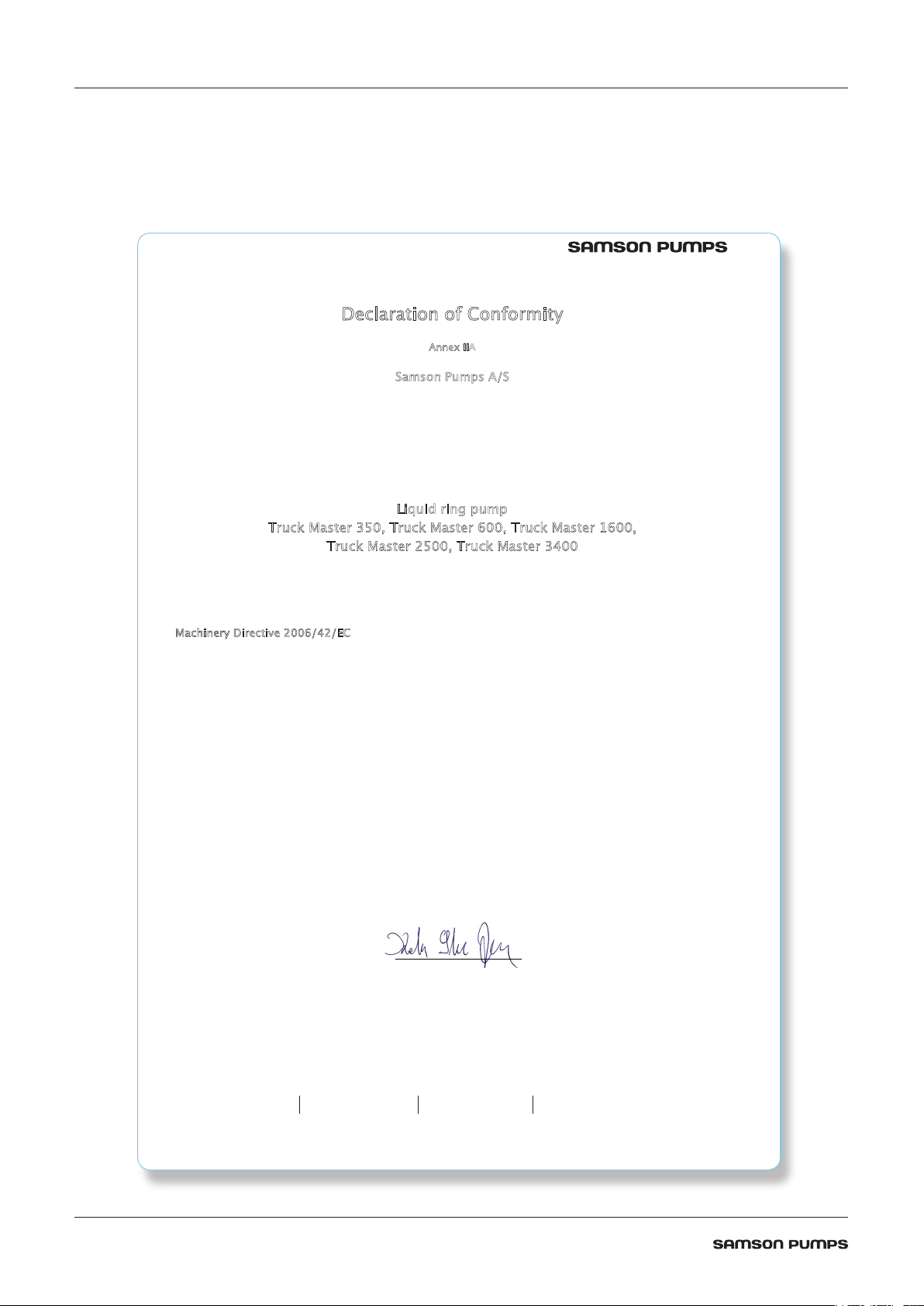
1.1 Declaration of conformity
Dec
Hereby declares that the following products:
ruck Master 350, Truck Master 600, Truck Master 1600,
T
ruck Master 2500, Truck Master 3400
T
laration of Conformity
Annex IIA
Samson Pumps A/S
Petersmindevej 21
DK-8800 Viborg
Liquid ring pump
Conforms to the directive:
Machinery Directive 2006/42/EC
I hereby declare that the liquid ring pumps are in conformity with the following harmonized standards:
DS/EN ISO 12100:2011 Safety of machinery - General principles for design - Risk assessment and risk
DS/EN 1012-2 + A1:2009 Compressors and Pumps - Safety requirements - Part 2: Vacuum pumps
The standards above only apply to the extent that it is relevant for the purpose of the pump.
The product must not be used before the complete system, which it must be incorporated in, has been conformity
assessed and found to comply with all relevant health and safety requirements of 2006/42/EC and other relevant
directives. The product must be included in the overall risk assessment.
Viborg, 03.10.2018 _______________________
Kelvin Storm Jensen
R&D Manager
Samson Pumps A/S
reduction
DOC4044
DOC4044
info@samson-pumps.com Samson Pumps A/S Petersmindevej 21
4
Page 5
1.2 Explanation of warning symbols
Important technical and safety instructions are shown by symbols. If the instructions are not performed
correctly, it can lead to personnel injuries or incorrect function of the pump.
To be used with all safety instructions that must be followed. A failure to follow the
instructions may result in injuries and/or incorrect machine operation
1.3 Field of application
Inlet of foreign objects can damage the pump
The pump is designed exclusively to pump gases, including atmospheric air
WARNING!
Avoid cavitation of the pump! For further information, see instruction manual for the
Samson Pumps vacuum limiter
It must be ensured that the inlet gas cannot react with the service liquid and create aggressive bonds that
break down the pump's components.
For other operating data, see specifications.
• The pump must only be used with media that is not aggressive to the pump's materials. See section 7
for components and materials.
1.4 Disposal
Samson’s liquid ring pump is manufactured so that most of the device can be reused/recycled.
Samson Pumps offer users of the company’s pumps the option of returning used pumps to be restored or
scrapped.
Alternatively, the pump must be taken apart and sorted into its separate components, by the customer
(see section 7 for the pump’s material).
These components must be disposed of in accordance with national regulations.
Truck Master 2500
5
Page 6
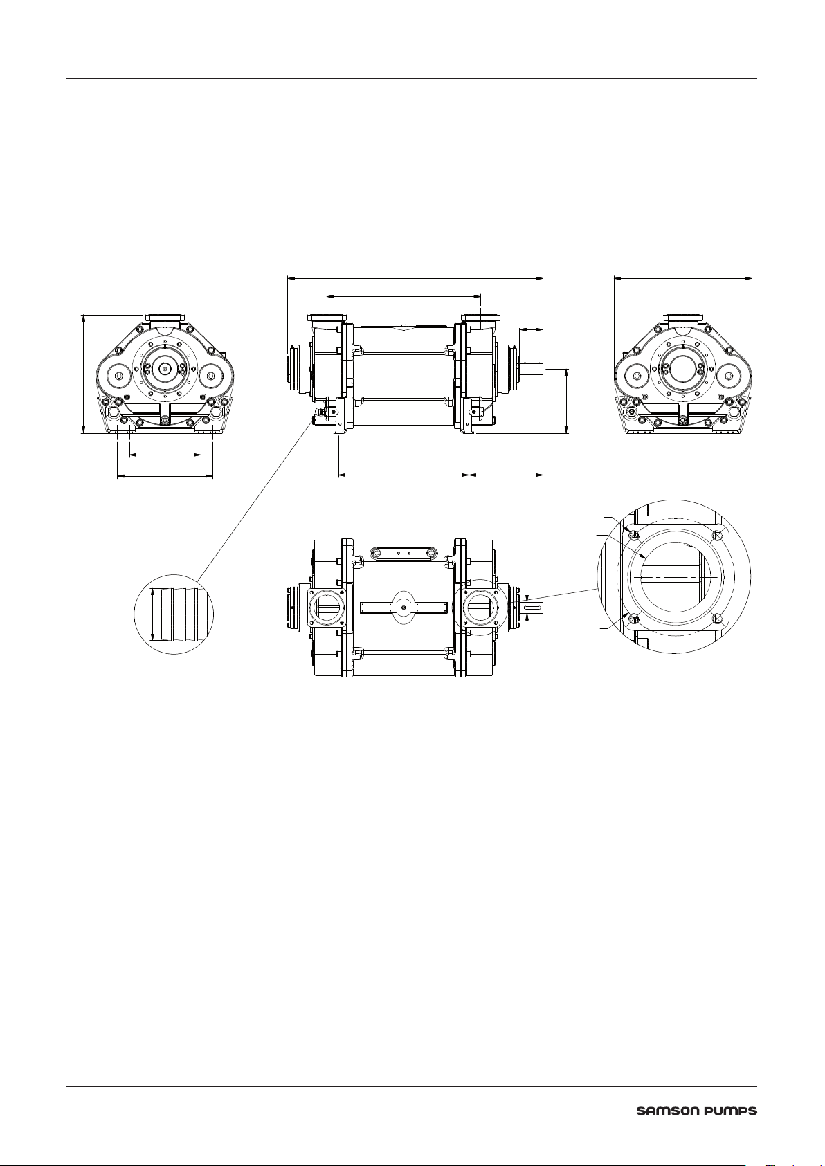
2 TECHNICAL DATA
498
48 k6Ø
270
20Ø
2.1 Dimensions
300
400
1074
647
100
579
549 312
M16x2
Ø107
Ø180
DOC1627354_1D
6
Page 7

2.2 Specifications
A failure to meet these specifications may result in damage to the pump
Description Minimum Maximum
Ambient temperature, operation Below 0°C - see chapter 5.3 -20°C 55°C
Ambient temperature, storage -20°C 55°C
Humidity - 100%
Intake temperature, suction side - 60°C
Intake temperature, service liquid - 60°C
Service liquid pipe connection, dimension ¾” -
Service liquid pipe connection, length - 6 m
Noise level - 80 dB(A)
Water volume - 34 L
Maximum radial load on drive shaft - 3480 N
1200 rpm 33 kW -
Heat input for cooler calculation
Revolutions 1200 rpm 1500 rpm
Pressure 150 mbar abs. 1 bar(g)
Lubricating grease
Weight 321 kg
1300 rpm 36 kW -
1400 rpm 41 kW -
1500 rpm 48 kW -
Type of grease SKF LGWA2
Automatic lubrication SKF LAGD 125/WA2
Truck Master 2500
7
Page 8
2.3 Power consumption and output
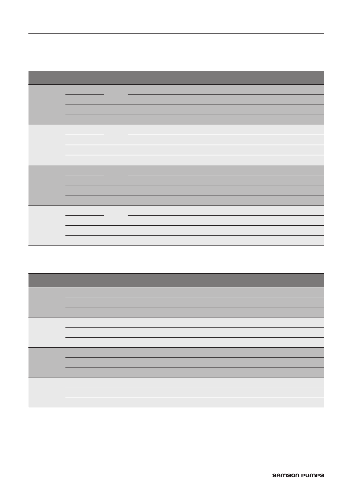
2.3.1 Vacuum
Vacuum [%] 80 70 60 50 40 30 20
1200 [rpm]
1300 [rpm]
1400 [rpm]
1500 [rpm]
Flow
Flow
Wet
Dry
[m³/h]
1261 1846 1777 1803 1852 1846 1860
941 1442 1545 1596 1699 1709 1738
Consumption [kW] 45
Torque [Nm] 358
Flow
Flow
Wet
Dry
[m³/h]
1522 1941 1914 1963 1972 1980 1965
1136 1517 1665 1737 1809 1833 1837
Consumption [kW] 48
Torque [Nm] 353
Flow
Flow
Wet
Dry
[m³/h]
1655 2126 2055 2159 2137 2205 2075
1235 1661 1787 1910 1960 2042 1939
Consumption [kW] 56
Torque [Nm] 382
Flow
Flow
Wet
Dry
[m³/h]
1962 2389 2361 2423 2445 2465 2322
1464 1866 2053 2144 2243 2282 2170
Consumption [kW] 64
Torque [Nm] 407
2.3.2 Pressure
Pressure [bar(g)] 0 0.25 0.5 0.75 1
Flow [m³/h] 1300 1226 1179 1070 993
1200 [rpm]
1300 [rpm]
1400 [rpm]
1500 [rpm]
The data Flow
• Air temperature 20°C
• Service liquid temperature 15°C
• Test performed with dry air and 1,013 mbar absolute pressure
• Tolerance ±10%
Consumption [kW] 39 43 49 54 59
Torque [Nm] 310 342 390 430 470
Flow [m³/h] 1425 1328 1261 1171 1097
Consumption [kW] 41 49 55 61 67
Torque [Nm] 301 360 404 448 492
Flow [m³/h] 1605 1569 1433 1341 1271
Consumption [kW] 54 55 61 68 74
Torque [Nm] 368 375 416 464 505
Flow [m³/h] 1824 1636 1633 1531 1390
Consumption [kW] 62 64 70 76 82
Torque [Nm] 395 407 446 484 522
is based on the following parameters:
Dry
8
Page 9
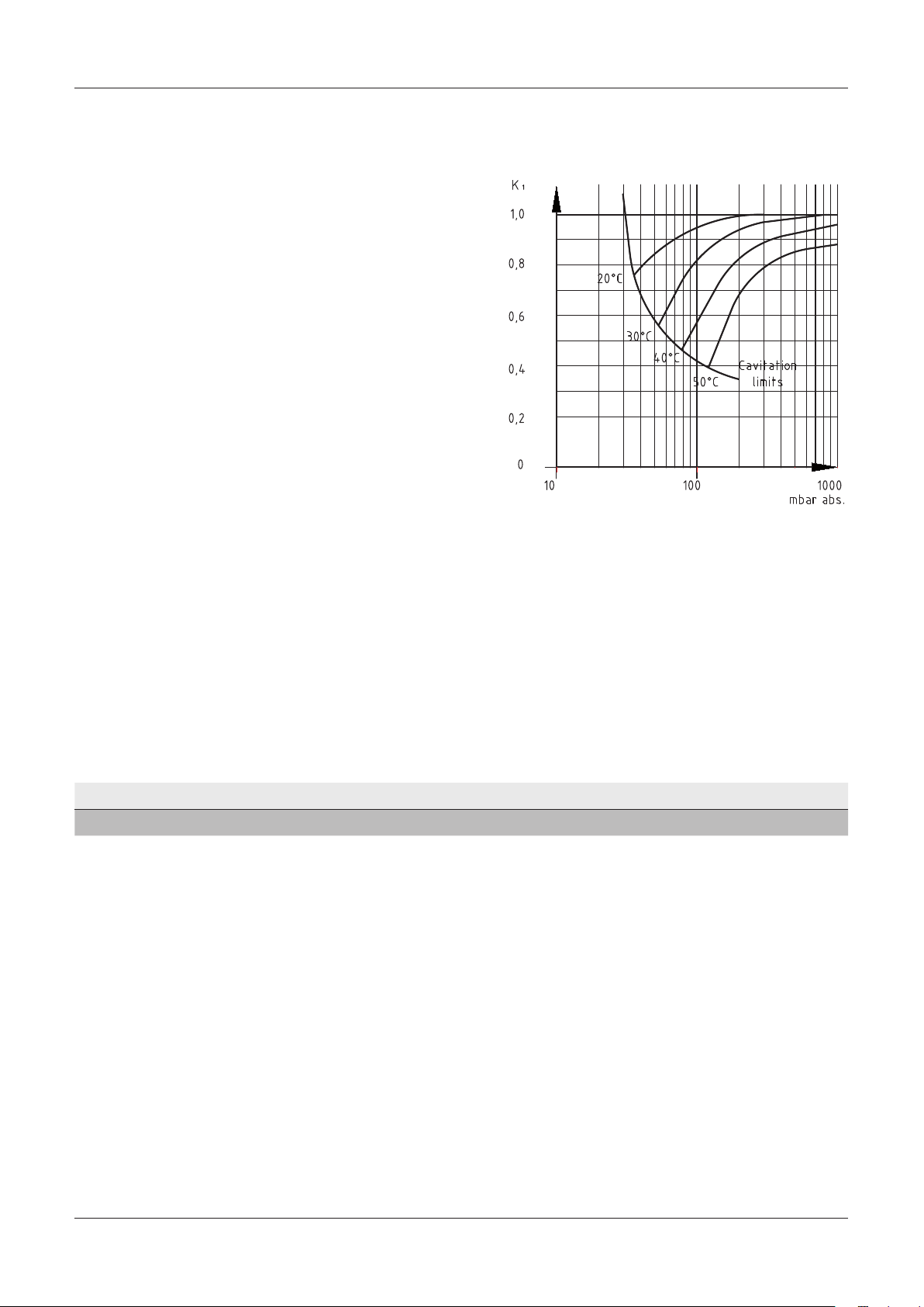
2.3.3 Correction factor - Temperature
When the temperature of the service liquid
exceeds 15°C, the pump’s capacity will be affected
with respect to the specified values.
To determine the output at a higher temperature,
the correction factor can be used.
Capacity at service liquid temperature
higher than 15°C :
= Q
x K
Q
t>15
15
1
DOC1628005_1A
2.3.4 Correction factor - Wet and dry gas
Normal atmospheric air contains water vapor. In this case water will condense inside the pump and will
create a higher flow.
Below you can find a correction factor table for the performance based on condensing gas with an inlet
temperature of 50°C 100% saturated and service liquid temperature of 15°C.
Suction pressure % Vacuum 80 70 60 50 40 30 20
Correction factor wet gas
K
1,34 1,28 1,15 1,13 1,09 1,08 1,07
Wet
The performance of the pump can thereby be calculated as:
V
= V
Dry
x K
Wet
Wet
Truck Master 2500
9
Page 10
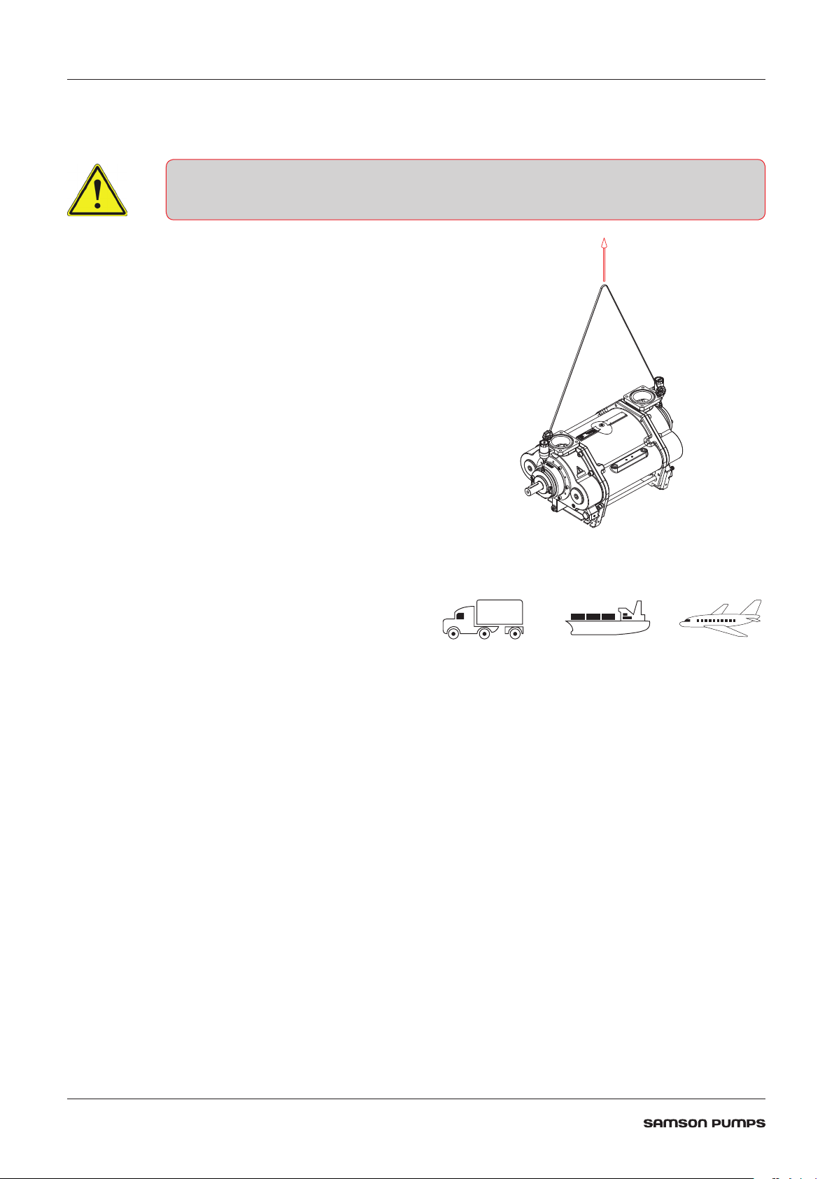
2.4 Handling and transport
The pump must not be used if it is damaged or the identification plate is missing
The pump must be transported in such way that
it is not exposed to vibrations and impacts that
can overload the bearings.
The pump must be inspected for damages upon
delivery. If the pump is damaged, it must not be
used and the damage must be reported to the
manufacturer.
Ensure that the pump’s identification plate
is intact and that the marking of the pump
corresponds to its use.
The pump must only be handled using approved
lifting eyes, in accordance with nationally
applicable regulations and only in a vertical
motion.
DOC1627355_1
The pump can be transported in the following
ways:
DOC11093A
10
Page 11
2.5 Pump storage and draining procedure
A failure to comply with the requirements for storing the pump may result in internal
damage to the device
If the temperature is below freezing point of the service liquid, it could damage the pump
Under these conditions, the pump must be drained completely
All plugs and protective covers must be fitted during storage
The pump’s service liquid is drained on delivery, and the pump can be immediately stored in accordance
with the technical specifications.
After operation, the pump can be stored for 30 days without further action.
If the pump remains out of operation for a longer period of time after use, its service liquid must be
drained, and the liquid supply to the pump must be shut off.
When emptying the pump, it is important that all chambers inside the pump are emptied.
The pump can be fitted with valves in the draining connections. See below.
Truck Master 2500
DOC1627356_1
11
Page 12

3 DESIGN OF A SYSTEM
Pos. Description
1
2
3
4
5
6
7
8
Liquid ring pump
Non return valve
4-way valve
Vacuum limiter
Service liquid valve
Fan cooler
Liquid separator
Dome valve
12
DOC1627390
Page 13

3.1 Function and design of a liquid separator
Together with the air there will be a water flow out of the pump up to 6 m3/h.
The water will be separated from the air in the liquid separator.
Depending of the size of particles, water will be carried with the water when the air velocity is more than
3-4 m/s.
The inlet speed to the separator can be more than 50 m/s and this must be reduced to 3 m/s.
Below you find an illustration showing how to reduce the speed and control that no water will be in contact
with the high velocity air stream. The round velocity reducer can be placed inside any tank geometry.
Air flow [m³/h] øD minimum [mm]
2500 540
2400 530
2300 520
2200 510
2100 500
2000 490
DOC1627391
øD so the velocity is below 3 m/s
H=4 to 6*d depending on the geometry. A smooth diameter conversion will give a low factor.
Truck Master 2500
13
Page 14

3.2 Air cooling with fan cooler
Compression of air inside the liquid ring pump will create heat that is transferred to the service liquid.
Therefore, it can be necessary to install a fan cooler depending on the expected use, the climate etc. The
time it takes to heat up the water also depends on for example ambient temperature, suction pressure,
amount of water and the cooling effect in the truck itself.
The operation temperature will go up until there is a balance between the heat input and the heat output.
So basically, there are only two things that can lower the operation temperature. Reduce the heat input or
increase the heat output.
The amount of water has no or only a little influence on the final operating temperature. The truck itself
will work as a big radiator and if there is a huge amount of water in the liquid separator and thereby good
contact area between the water and the steel tank, it will give a higher cooling effect. This in combination
with low ambient temperature and short time of operation, could mean that the truck can operate without
any additional cooling.
In general, the time it takes to heat up the water can be calculated from the formula below.
x m x Δt
C
=
p
Q
t
sec
t
C
Δt
m
Q
Example:
We have a tank with 300 litres of water corresponding to 300 kg. The heat input is 30 kW.
How long will it take to heat it up from 20°C to 40°C ?
The temperature will continue to go up until the steel construction can absorb the heat and transfer it to
the surroundings.
With a temperature difference on 20°C it is typical to have a radiator affect in a truck on somewhere
between 5 to 20 kW depending on the construction.
Time in seconds
=
sec
Heat capacity of the media. Water= 4,2
=
p
Temperature difference
=
Mass of the media heating up [Kg]
=
Heat input in [kW] See specifications, chapter 2.2
=
x 300 x 20
4,2
t
=
sec
30
= 840 s
= 14 min
The table below shows truck radiator effect at a temperature difference of 20°C.
5 kW 10 kW 20 kW
Small liquid separator mounted
external from the truck tank
Water content below 100 L
Small liquid separator inside
slurry tank. Located with only
minor contact to the product
Water content 300 L
Normal liquid separator inside
slurry tank with good contact to
the product
Water content 400 L
14
Page 15

3.3 Fan cooler
The fan cooler will increase the heat output from the construction and thereby stabilize the temperature
at a lower level. However, this cooler will use the air to cool down the water and therefore we will always
see that the temperature will be stabilized above the ambient temperature. It’s very simple to find the right
cooler based on the curves from the cooler manufacturer. Typically you will find the cooler capacity as kW/
Δt meaning for example 1.5 kW cooler capacity each °C in temperature difference between the water and
the air. Note that the water flow through the cooler will also affect the cooling capacity.
Typical fan cooler characteristic.
Practical calculation example:
The truck is used mostly to work with an operation pressure around 70% vacuum. From the technical data
sheet, we find the heat input from the pump to be 35 kW.
The liquid separator is built inside the slurry tank with a good contact to the product and a radiator effect
estimated to 20 kW with a temperature difference of 20°C.
The truck will work with ambient temperature up to 28°C during the summer and we will accept a maximum
temperature on 40°C.
First, we have to reduce the radiator effect based on a temperature difference of 12°C.
DOC1627392
12
Q
out Truck
The total cooling effect required is thereby:
= 20 x
= 12 kW
20
Q
out Pump
- Q
Truck Master 2500
out Truck
= 35 - 12 = 23 kW
15
Page 16

Summary
Pump model Description Truck Master 2500
Heat input from technical specifications Q
Ambient temperature t
in Pump
amb
35 kW
28°C
Maximum Working Temperature of the water.
This is determined by you. The temperature
t
op
40°C
has influence on the pump performance
Temperature difference Δ
Truck radiator effect based on 20 °C in
temperature difference
Truck radiator effect based on 12 °C in
temperature difference
Total cooling requirement from fan cooler Q
t
Q
out Truck 20
Q
out Truck 12
fan cooler
tOp- t
20 kW
12/20*20 = 12 kW
Q
= 12°C
amb
in Pump-Qout Truck 12
= 35-12 = 23 kW
We need to find a fan cooler that can transfer 23 kW with a temperature difference on 12°C.
That is 1,92 kW/°C.
If we for example accept a higher temperature, for instance 48°C, we will have full cooling effect from the
truck on 20 kW and a cooling requirement on 15 kW. The fan cooler we need to find is thereby on 15/20 =
0,75 kW/°C and a big difference to the bigger model calculated above.
3.4 Water consumption
It is possible to design the liquid separator so that almost 100% of the water is separated from the air.
However, the air will be heated up and thereby it can content more water. Also, the relative humidity will go
up and end near 100%.
So, the air will flow into the pump with maybe 50% relative humidity at a low temperature and be
discharged at a higher temperature and humidity. Therefore, there will be an evaporation from the system.
Choose your water temperature
Temp.
20°C 30°C 40°C 50°C 55°C
Vacuum
50% 18 27 53 93 152
70% 10 16 32 56 91
80% 5 11 21 37 60
Water consumption Liters per hour
3.5 Dome valve system
The liquid ring pump can handle liquid and particles in the inlet but it is of course
recommendable to avoid this.
A dome valve or floating valve will ensure that the suction will be closed when the liquid
level reaches the top of the tank.
In many situations there will be foam on the liquid surface inside the tank. It can be
difficult to avoid that this will be transported into the suction line before the dome valve
will close.
Therefore, it will be recommended to make a combination of a filter and dome valve as
illustrated below.
The filter will prevent particles lifted by the foam to enter the pump.
DOC1627393
16
Page 17

3.6 Cavitation
When the temperature reaches the boiling point of the water, steam bobbles will be created in the liquid
ring.
These bobbles cannot exist when they enter the discharge side of the pump and therefore they will
collapse. The impact force on the surface of the rotor and flow plate will damage the pump and can lead to
a total breakdown. It is a very harmful situation that must be avoided.
It is the combination of the pressure and the temperature that will lead to the cavitation. Therefore, it is
recommended to install a cavitation valve, see illustration below that shows a clockwise rotating pump.
If counter-clockwise rotating pump, mount in opposite manifold.
DOC1627417
Below you find the boiling point of water as a function of the pressure.
Vacuum 50% 75% 80% 90%
Temperature °C 80 64 59 44
Maximum discharge temperature 70 50 40 30
Note that the temperature of the gas inside the pump will heat up the water and the water surface therefore
will become a higher temperature than the measured temperature on the discharge side of the pump.
Cavitation will therefore start at a lower temperature and the maximum discharge temperature of the water
must be kept lower.
3.7 Service liquid requirement
During operation it is normal that small amount of product will enter the pump, or the gas will react with
the water which becomes aggressive.
A normal recommendation is to add glycol to the water in order to protect the liquid ring pump. Glycol will
protect the pump and for example the aluminum cooler, but shall only be used in periods with temperature
below freezing point.
Due to economical aspect it is more efficient to drain the liquid separator and refill with fresh water instead
of protecting with glycol and drain the separator more rarely.
Truck Master 2500
17
Page 18

4 INSTALLATION AND START-UP
4.1 Securing the pump
Installation requirements must be observed, otherwise there is a risk of damage
The pump must be installed on a stable foundation, which must be level and stable, so that the pump is not
twisted or exposed to a profile distortion.
The pump must be installed with M16 bolts on all four legs, which must be tightened to 180 Nm (A).
A
A
DOC1627358_5
4.2 Connections to the pump
• Check for foreign objects in the pump and physical damage on pump
• Gaskets to be handeled with highest degree of caution
• Gasket and sealing surfaces must be cleaned before assembly
Immediate before connecting the pipes, remove protective covers. Connection of the pump’s suction and
pressure pipe connections must be made with a gasket in between (C).
The M16 bolts must be tightened with 180 Nm (B).
In order to prevent tensions in the pump, the pipe connections (A) must be tensionless while tightening the
bolts.
C
A
B
18
DOC1627358_2
Page 19

4.3 Connecting the service liquid
The service liquid must be connected to the pump at the hose connection, see illustration below.
DOC1627356_5
4.4 Transmission
The pump can be connected direct or through belt transmission. For belt transmission, it must be ensured
that the permissible radial force is not exceeded. See specifications.
For belt transmission, note the direction of rotation, see illustration below.
DOC1627416_1
Truck Master 2500
19
Page 20

4.5 Prior to start-up
• Do not start the pump without service liquid, as this will damage the mechanical shaft
seals
• Do not start the pump if it is completely filled with service liquid
• Do not start the pump before the grease cartridges have been activated, as this can
damage the pump (if equipped)
• Stop the pump immediately if the rotational direction does not correspond to the
directional arrow
• A failure to follow the above guidelines may result in damage to the pump
Activating the grease cartridges (Accessories)
Turn the handle in NDE clockwise to position 12.
Turn the handle in DE clockwise to position 12.
The pump has been lubricated from factory and is ready to start.
NDE
DOC1627356_6
DE
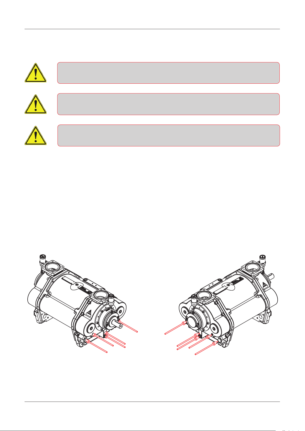
4.6 Direction of rotation
Check the direction of rotation by briefly starting the pump.
The direction of rotation of the rotor must correspond to the direction arrow!
Below left, a right-side pump is shown which has a clockwise direction of rotation (CW)
Below right, a left-side pump is shown which has a counter-clockwise direction of rotation (CCW)
DOC3707
20
DOC1627357_1 DOC1627414_1
Page 21

5 SERVICE, OPERATION, MAINTENANCE AND INSPECTION INTERVALS
A failure to observe the inspection intervals described in table below may result in
damage to the pump
Section Operation Interval
5.1 Drain liquid separator to remove contaminants Weekly
5.2 Check grease cartridges (if equipped) Weekly
5.3 Winterization When below 0°C
5.4 Lubrication of bearings Per 500 duty hours
5.5 Inspection and cleaning of service liquid’s supply pipe Monthly
5.6 Inspection and cleaning of internal channels Monthly
5.1 Draining the liquid separator
While the pump is stopped, the liquid separator must be drained to remove contaminants.
5.2 Check grease cartridges
If the pump is equipped with an automatic lubrication feature. It must be inspected and
replaced as needed.
When the pump is commissioned for the first time, the cartridges must be activated by
turning the arrow in the clockwise direction.
The cartridge is set to 12, which corresponds to an emptying time of 12 months.
The cartridge must be replaced when empty.
It is only allowed to use automatic lubricator of type LAGD 125/WA2.
DOC3707
5.3 Winterization
If the pump needs to be used at a temperature below freezing point of the service liquid, it is necessary to
protect the liquid from freezing by adding anti freeze liquid.
Truck Master 2500
21
Page 22

5.4 Lubrication of bearings
Over-lubrication of bearings may result in bearing damage! Do NOT exceed the
amount of grease specified below!
The bearings must be lubricated with grease of type SKF LGWA2, per 500 duty hours.
It is recommended to lubricate the bearings while pump is running.
Lubrication interval per 500 duty hours
Drive end (DE) 4 g
Non drive end (NDE) 3 g
NDE
DOC1627356_7
5.5 Inspection and cleaning of service liquid’s supply pipe
The pipe connection between the liquid separator and pump must be inspected at least once a month, and
any contaminants must be removed.
5.6 Inspection and cleaning of internal channels
The pump is designed with internal water channels for lubrication of the mechanical shaft seals.
Remove the plug as illustrated below and clean the channel using a ø5 mm 150 mm long screw driver or
similar.
DE
22
DOC1627356_8
Page 23

6 TROUBLESHOOTING
Problem Cause Effect Corrective measure
The pump is unable to
create a vacuum
The start-up power is
too high
Noise during operation • Cavitation • Severe damage to the
Leakage from the
bearing housing’s drain
holes
• Service liquid valve is
closed
• The pump is not
receiving enough
service liquid
• The temperature of the
service liquid is too
high
• Too much service liquid
in the pump prior to
start-up
• Damaged shaft seal • Bearings may become
• Reduced output
• The pump can become
damaged during
cavitation
• Noise at start-up and
possible overload of
the power supply
pump and potential risk
of breakdown
damaged
• Potential risk of
explosive gas leak
• Check service liquid
valve
• Check the liquid
supply
• Stop the pump
and wait until
the temperature
has dropped to
a sufficient level,
or lower the
temperature of the
service liquid inlet
• Check the stop valves
in the liquid supply
for leakage
• Increase the suction
pressure or lower the
temperature of the
service liquid
• Stop the pump
and contact the
manufacturer
Truck Master 2500
23
Page 24

7 SPARE PARTS AND TOOLS
7.1 Marking and identification
The pump is equipped with an identification plate as shown below.
CE CONFORMITY MARK
ORDER CONFIRMATION NO. / A NO.
Configuration example:
Type:
Model:
Rotation:
Rotor type:
Pump housing:
Shell:
Flow plates:
Mechanical shaft seals:
Gaskets:
Colour:
MANUFACTURING DATE / SERIAL NO.
PRODUCT CODE
TM 2500 R 0 S S B 0 0 T SD
Documentation:
24
Location of ID plate
DOC107939
Page 25

7.2 How to order
Example:
Model:
2500
Rotation:
Clockwise
Counter clockwise
Rotor type:
Welded AISI 316
Pump housing:
Cast iron EN-GJL-250; EN1561
Shell:
Cast iron EN-GJL-250; EN1561
Flow plates:
Cast iron EN-GJL-250; EN1561
Bronze GC-CU Sn10 DIN1705
TM 2500 R 0 S S S 0 0 P SD
2500
R
L
0
S
S
S
B
Mechanical shaft seals:
NBR / AISI 316
Gaskets:
Oakenstrong
Colour:
Grey primer
Truck Master Orange
On request
Documentation:
Samson standard
ATEX Zone 1
ATEX Zone 0
Truck Master 2500
0
0
P
T
X
SD
X1
X5
25
Page 26

8
11
9
26
31
7.3 Spare parts
56
53
52
51
35
1
5
6
*
13
44
50
49
16
45
12
2
24
*
48
3
36
22
34
*
17
32
15
4
26
41
58
47
*
Page 27

8
1
26
10
19
21
55
57
54
40
*
14
33
23
31
18
20
7
43
38
25
*
26
30
27
42
29
39
*
37
*
46
28
*
1
9
*
*
- Included in gasket set.
*
DOC1627359_1
Truck Master 2500
27
Page 28

Pos. Part number Description Qty. Material
1 - Identification plate 1 Stainless steel
2 - Direction arrow 1 Aluminum
3 1615002 Pump housing 2 Cast iron
4 1615003 Bearing housing 2 Cast iron
5*
6*
7 1615045 Gasket set Truck Master 2500 1 -
8 1615012 Shell 1 Cast iron
9 1615045 Gasket set Truck Master 2500 1 -
10*
11 1615045 Gasket set Truck Master 2500 1 -
12 1615017 Retainer 2 Stainless steel
13 1615019 Bearing cover DE 1 Cast iron
14 1615020 Bearing cover NDE 1 Cast iron
15 1615021 Rear cap 2 Stainless steel
16 1615022 Foot bracket 2 Steel
17 1615024 Pipe fitting 1 Brass
18 1615025 Pipe for water supply 1 Stainless steel
19 1615030 Plug 2 Brass
1615005 Rotor R 1 Stainless steel
1615034 Rotor L 1 Stainless steel
1615010 Flow plate 1 Cast iron
1615036 Flow plate 1 Bronze
1615014 Flow plate 1 Cast iron
1615038 Flow plate 1 Bronze
20 1620203 Bush 4 Sintered Bronze
21 910300102 Allen screw 16 Steel
22 910100148 Washer 24 Stainless steel
23 910300072 Allen screw 4 Steel
24 910300075 Allen screw 16 Steel
25 910300080 Allen screw 4 Steel
26 910300182 Plug 6 Steel
27 910300184 Plug 2 Steel
28 910300185 Plug 4 Steel
29 1615040 Mounting sleeve 1 Brass
30 910300188 Plug 5 Steel
31 910300281 Plug 4 Steel
32 915000023 Parallel key 1 Steel
33* 915000050 Grease nipple 2 Steel
34 922000265 Mechanical shaft seal 2 Steel
35 1615045 Gasket set Truck Master 2500 1 -
* -See section 7.1 for identification of pump.
**-Optional. Not equipped as standard.
28
Page 29

Pos. Part number Description Qty. Material
36 1615045 Gasket set Truck Master 2500 1 -
37 1615045 Gasket set Truck Master 2500 1 -
38 1615045 Gasket set Truck Master 2500 1 -
39 1615045 Gasket set Truck Master 2500 1 -
40 1615045 Gasket set Truck Master 2500 1 -
41 1615045 Gasket set Truck Master 2500 1 -
42 925000246 Hose nipple 1 Brass
43 930000314 Ball bearing 1 Steel
44 1615045 Gasket set Truck Master 2500 1 -
45 910300455 Allen screw 6 Steel
46 910300476 Allen screw 8 Steel
47 930200020 Shaft nut 2 Steel
48 1624020 Sticker Warning! 2 Plastic foil
49** 1634773 Thread nipple 2 Brass
50** 915000215 Push-in nipple 2 Brass
51** 915000232 Clamp for automatic lubricator 2 Plastic
52** 915000225 Automatic lubricator LAGD 125/WA2 2 Plastic / grease
53** 915000214 Push-in nipple 2 Brass
54** 910300447 Allen screw 2 Stainless steel
55** 910100125 Washer 2 Stainless steel
56** 915000217 Plastic pipe 0,1 m Plastic
57** 915000217 Plastic pipe 0,1 m Plastic
58 930000317 Roler bearing spherical 1 Steel
* -See section 7.1 for identification of pump.
**-Optional. Not equipped as standard.
Truck Master 2500
29
Page 30

7.4 Adaptor
DBI dut for grease nipple cap, yellow
194830001614
HRC rubber element 180
193240004913
Half coupling HRC-F 180 For Taperlock 2517
293240004812
Taperlock bush 2517-48193230000411
Taperlock bush 2517-45193230000310
Sealing ring 50x7x8 DIN 3760A NBR TYpe: OA
19222002669
Grease nipple M8x1,25 H1
19150000508
Plug 3/4
” black conical hexagon.
3910300186
7
M12x55 Allen bolt DIN 912 stainless steel A4
4
9103000796
M20x75 Steel Bolt ISO 4014 8.8 FZV
2910000508
5
M20 Washer DIN 125-A 8.8 FZV
4
910000423
4
M20 Nut DIN 934 8.8 FZV29100004223
Flange for adapter and Parker motor model: F12-110/125 ISO, Machinined
116346232
Adapte; Machined
116150321
Title
Qty
Part numberPos
7
148
5
4
2
12
10
13
11
1 3
4
9
6
DOC1627361_2
Pos. Part number Description Qty. Material
1 1615032 Adaptor 1 Cast iron
2 1634623
3 910000422 M20 Nut 2 Steel
4 910000423 M20 Washer 4 Steel
5 910000508 M20x75 Bolt 2 Steel
6 910300080 M12x55 Allen bolt 4 Steel
7 910300186 Plug 3/4” 3 Steel
8 915000050 Grease nipple 1 Steel
9 922200266 Radial shaft seal 1 Rubber / Steel
10 932300003 Taperlock bush 1 Cast iron
11 932300004 Taperlock bush 1 Cast iron
12 932400048 Half coupling 2 Cast iron
13 932400049 Rubber element 1 Rubber
14 948300016 DBI dut for grease nipple cap 1 Plastic
Flange for adaptor
Parker motor model: F12-110/125 ISO
1 Cast iron
30
Page 31

7.5 Gasket set
DOC11587
Pos. Part number Description Qty. Material
7 1615011 Gasket for pump housing / flow plate 1 mm 2 Paper
1615013 Gasket for shell / flow plate 0,5 mm 2 Paper
9
11 1615015 Gasket for pump cover / housing 5 mm 2 Rubber
35 922100085 O-ring Ø134,30x5,70 2 Rubber
36 922100370 O-ring Ø20,0x2,5 2 Rubber
37 922100371 O-ring Ø23,39x3,53 4 Rubber
38 922100368 O-ring Ø113,97x2,62 3 Rubber
39 922100369 O-ring Ø30,0x3,0 4 Rubber
40 922200225 Radial shaft seal 60x80x8 2 Rubber / Steel
41 922200266 Radial shaft seal 50x72x8 1 Rubber / Steel
44 930200016 Lock washer 2 Steel
1615023 Gasket for shell / flow plate 0,8 mm 2 Paper
1615029 Gasket for shell / flow plate 1 mm 2 Paper
See spare parts drawing (DOC1627359_1) for positions.
Truck Master 2500
31
Page 32

2
6
1
3
5
4
7.6 Special tool set
Pos. Part number Description Qty. Material
1 1629239 Mandrel radial shaft seal Ø50 + Ø60 1 Plastic
2 1629237 Machined bearing cap complete 1 Steel
3 1629190 Bearing mounting tool set NDE 1 Steel
4 1629191 Bearing mounting tool set DE 1 Steel
5 1629235 Bearing tool set 1 Steel
6 1629240 Mounting sleeve for Ø60 mechanical shaft seal 2 Plastic
DOC1629241_1
32
Page 33

Notes:
Truck Master 2500
33
Page 34

Notes:
34
Page 35

Notes:
Truck Master 2500
35
Page 36

SAMSON PUMPS
Samson Pumps is the only company in the world to specialise exclusively in
liquid ring vacuum pumps. Samson pumps are made in Denmark and used
around the globe. We offer worldwide delivery, and we export to more than 80
countries around the world.
For over 40 years, our name has been synonymous with the strongest pumps
for vacuum trucks and tankers. We constantly adapt our products to meet the
changing needs of our customers. Today, it is not enough to simply produce a
pump. Products must be refined so the customer can concentrate on what they
do best. We therefore offer a wide range of standardised components that allow
our customers to build vacuum systems without the need for specialist in-house
expertise.
Strength and durability are our hallmarks! We have often heard from customers
that our pumps are working in many years, and in most cases without the need
for maintenance or repair. This emboldens us to say that we have the strongest
program of pumps on the market.
E-Mail info@samson-pumps.com Samson Pumps A/S Petersmindevej 21
Web www.samson-pumps.com Phone | +45 87 50 95 70 DK-8800 Viborg
 Loading...