

Samson TROVIS SAFE 3730 Series, TROVIS SAFE 3730-6, 3730 Series, 3730-6 Operating Instructions Manual
Page 1
Series 3730
TROVIS SAFE 3730-6 Electropneumatic
Positioner
EXPERTplus Valve Diagnostics
Operating Instructions
EB 8389-1S EN
Firmware version 1.1x
Edition May 2015
Page 2
Denition of signal words
DANGER!
Hazardous situations which, if not
avoided, will result in death or serious
injury
WARNING!
Hazardous situations which, if not
avoided, could result in death or serious injury
2 EB 8389-1S EN
NOTICE
Property damage message or malfunction
Note:
Additional information
Tip:
Recommended action
Page 3

Contents
1 Description ....................................................................................................7
1.1 General ........................................................................................................7
1.2 Start-up .........................................................................................................9
1.3 Diagnostic functions .....................................................................................10
1.3.1 Type of application.......................................................................................11
1.3.2 Assessment ..................................................................................................11
2 Monitoring ..................................................................................................13
2.1 Status messages ...........................................................................................13
2.1.1 Resetting status messages .............................................................................13
2.1.2 Condensed state ..........................................................................................17
2.2 Logging .......................................................................................................18
3 Data logger ................................................................................................21
3.1 Permanent data logging ...............................................................................21
3.2 Triggered data logging ................................................................................. 22
3.2.1 Triggered by condensed state ........................................................................22
3.2.2 Triggered by set point, valve position, set point deviation or signal pressure ......23
3.2.3 Triggered by binary input .............................................................................24
3.2.4 Triggered by internal solenoid valve/forced venting ........................................25
3.2.5 Triggered by set point or internal solenoid valve/forced venting .......................25
4 Valve signature ...........................................................................................27
4.1 Reference graphs .........................................................................................28
4.1.1 Analysis and monitoring ...............................................................................28
4.2 Valve signature, signal pressure(x) .................................................................29
4.2.1 Analysis and monitoring ...............................................................................30
4.3 Course of supply pressure .............................................................................31
4.3.1 Analysis and monitoring ...............................................................................32
4.4 Valve signature, friction(x) ............................................................................33
4.4.1 Analysis and monitoring ...............................................................................34
4.5 Resetting single status messages ....................................................................34
5 On/off valve ...............................................................................................37
5.1 Diagnostics for on/off valve ..........................................................................38
5.2 Analysis and monitoring ...............................................................................39
5.3 Resetting single status messages ....................................................................40
EB 8389-1S EN 3
Page 4

Contents
6 Valve position x histogram ..........................................................................41
6.1 Analysis and monitoring ...............................................................................42
6.2 Resetting single status messages ....................................................................42
7 Set point deviation e histogram ....................................................................44
7.1 Analysis and monitoring ...............................................................................45
7.2 Resetting single status messages ....................................................................46
8 Cycle counter histogram ..............................................................................49
8.1 Analysis and monitoring ...............................................................................50
8.2 Resetting single status messages ....................................................................50
9 Leakage sensor ...........................................................................................53
9.1 Start-up of the leakage sensor .......................................................................54
9.1.1 Manufacturer reference ................................................................................54
9.1.2 Process reference .........................................................................................57
9.2 Short-term monitoring ..................................................................................62
9.2.3 Resetting single status messages ....................................................................63
9.3 Long-term monitoring ...................................................................................63
9.3.1 Resetting single status messages ....................................................................63
9.4 Sound level(x) ..............................................................................................64
9.4.2 Resetting single status messages ....................................................................64
10 Course of end position .................................................................................67
10.1 Analysis and monitoring ...............................................................................68
10.2 Resetting single status messages ....................................................................68
11 Valve dead band ......................................................................................... 69
11.1 Resetting single status messages ....................................................................70
12 Partial stroke test (PST) ................................................................................73
12.1 Start triggered by the set point ......................................................................78
12.2 Start triggered by the binary input.................................................................78
12.3 Analysis and monitoring ...............................................................................79
12.4 Resetting single status messages ....................................................................80
13 Full stroke test (FST) .....................................................................................83
13.1 Analysis and monitoring ...............................................................................87
4 EB 8389-1S EN
Page 5

Contents
13.2 Resetting single status messages ....................................................................87
14 SIL operator test ..........................................................................................88
14.1 Analysis and monitoring ...............................................................................90
15 Binary input ................................................................................................ 91
®
16 Dynamic HART
variables ............................................................................93
17 Appendix ....................................................................................................95
17.1 Code list ......................................................................................................95
17.2 Error messages and recommended corrective action .....................................102
17.3 Diagnostic data points saved in a non-volatile memory ................................. 107
17.4 Resetting parameters ..................................................................................108
EB 8389-1S EN 5
Page 6
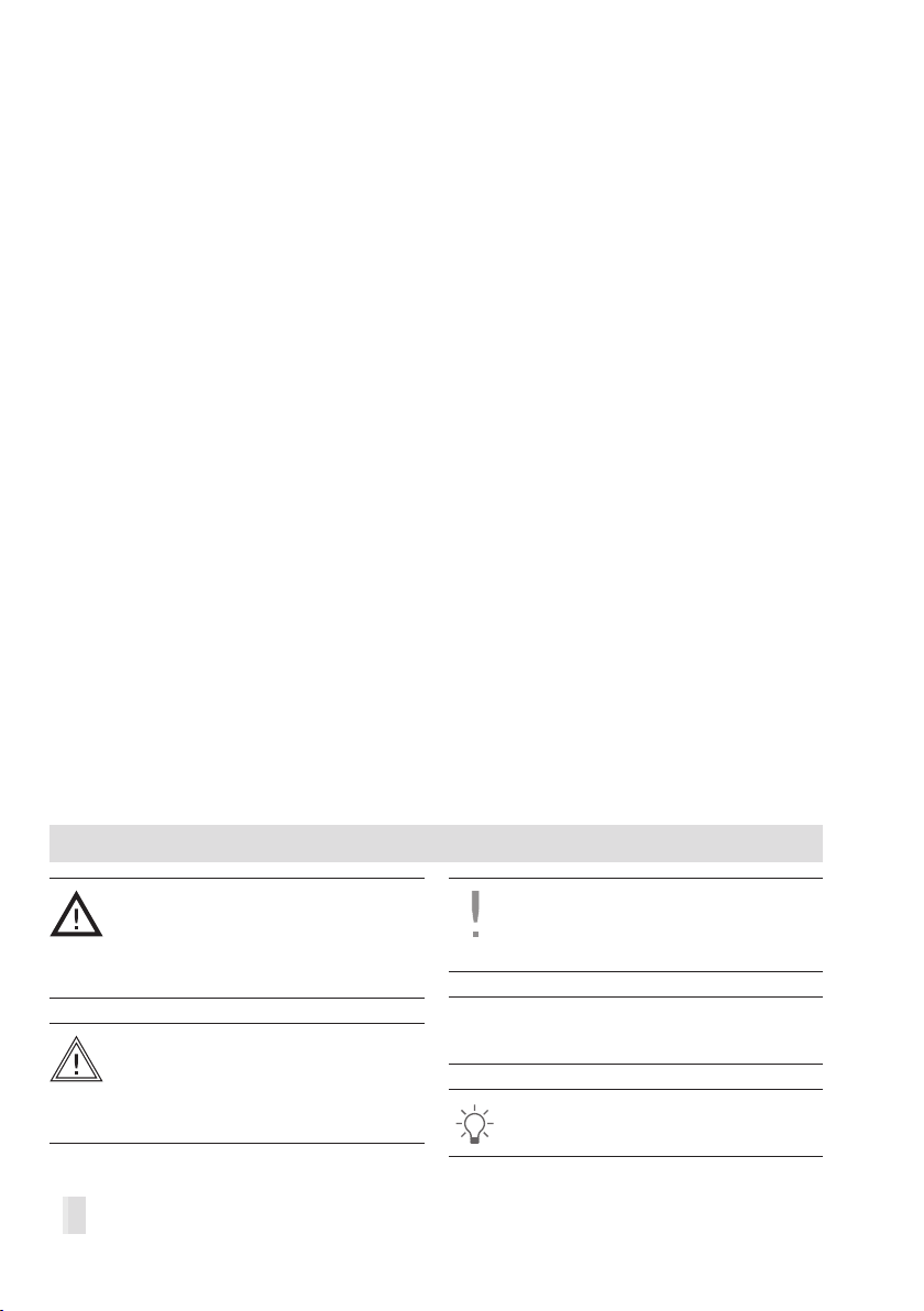
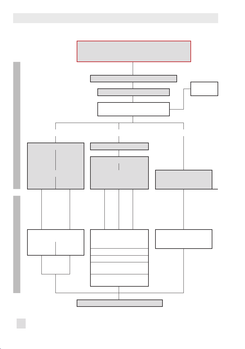
Overview
Throttling service
On/off service
No conguration
required for
monitoring
Travel histogram
u Section 6
Set point deviation
histogram e
u Section 7
Cycle counter
histogram
u Section 8
Course of end
position
u Section 10
Note:
− Tests highlighted in red border require an initialization with valve signature
− Tests highlighted in gray can optimize the proper functioning of safety equipment according to IEC61508 and IEC61511,
provided these tests are performed regularly.
Conguration
required for
diagnosis
Data logger
u Section 3
Valve signature
u Section 4
Packing
u Section 8
Leakage sensor
u Section 9
Valve dead band
u Section 11
Full stroke test (FST)
u Section 13
No conguration
required for
monitoring
Travel histogram
u Section 6
Set point deviation
histogram e
u Section 7
Cycle counter
histogram
u Section 8
Course of end
position
u Section 10
Conguration
required for
diagnosis
Data logger
u Section 3
On/off diagnosis
u Section 5
Packing
u Section 8
Leakage sensor
u Section 9
Valve dead band
u Section 11
Partial stroke test
(PST)
u Section 12
Full stroke test (FST)
u Section 13
6 EB 8389-1S EN
Page 7

Description
1 Description
1.1 General
These instructions supplement the standard
Mounting and Operating Instructions for the
TROVIS SAFE3730-6 Positioner
(uEB8384-6S EN).
EXPERTplus is a diagnostic rmware inte-
grated into the positioner which allows the
predictive, status-oriented maintenance of
valves with pneumatic actuators.
EXPERTplus records the valve condition while
the process is running (in automatic mode)
and generates messages on the required
maintenance work. In addition, numerous
tests can be performed in manual mode to
pinpoint emerging faults.
The diagnostic functions of EXPERTplus are
completely integrated into the positioner. Diagnostic data are compiled, saved and ana-
lyzed in the positioner itself. Classied status
messages on the state of the valve are generated from the analysis.
All the parameter settings that are changed
must also be downloaded onto the positioner to allow them to become effective.
Local operation
Some parameters can be changed at the positioner as well as over the operator interface.
T
he positioner code of these parameters are
written in parentheses. Refer to the Mounting
and Operating Instructions of the TROVIS
SAFE3730-6 Positioner (EB8384-6SEN) for
a list of all parameters that can be changed
at the positioner.
The operation described in the following
sections illustrates operation using TROVISVIEW4. The default settings of the positioner and TROVIS-VIEW4 are written in
square brackets [ ]. Settings highlighted in
gray refer to operation using TROVISVIEW4.
Operation using TROVIS-VIEW 4/DD/DTM/
eDD
EXPERTplus allows the parameters to be
viewed or changed using the TROVIS-
VIEW4 software or DD/DTM/eDD.
TROVIS-VIEW4 · SAMSON operator inter-
face used to congure various SAMSON de-
vices
− DTM · Device type manager to describe
the device and communication properties
− DD/eDD · Device description/enhanced
device description
EB 8389-1S EN 7
Page 8
DescriptionDescription
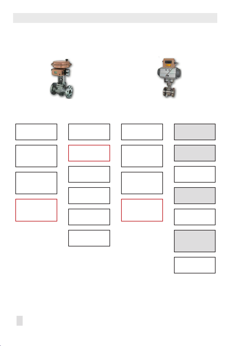
Initialization mode
â â â
MAX NOM MAN/MAN2
â
Initialization including valve
signature
ß à
Yes
START-UP
â â
Zero
Valve signature (D1)
Code 81 Code 81
ß Not successful
ß Successful
Automatic change to
AUTO operating mode
à
No
Throttling or on/off service
Later recording of
reference graphs
â
Operating mode = MAN
Valve signature (D1)
All reference values are overwritten!
ß Not successful
â
Operating mode = AUTO
ß
8 EB 8389-1S EN
Page 9

Description
1.2 Start-up
The positioner must be initialized to use the
full scope of the valve diagnostics. During initialization the positioner adapts itself optimally to the friction conditions and the signal
pr
essure required by the control valve. The
positioner can be initialized using one of the
following initialization modes: maximum
range (MAX), nominal range (NOM), manual
setting 1 (MAN) and manual setting 2
(MAN2).
− Maximum range (MAX)
Initialization mode for simple start-up of
valves with two clearly dened mechanical end positions, e.g. three-way valves
− Nominal range (NOM)
Initialization mode for all globe valves
− Manual setting 1 (MAN)
Initialization mode for globe valves re-
quiring OPEN position to be entered
manually
− Manual setting 2 (MAN2)
Initialization mode for globe valves re-
quiring the end positions (OPEN and
CLOSED positions) to be entered manually
The type of application, pressure limit and
the start-up parameters required for the selected initialization must be entered to initialize the positioner.
Note:
Positioner start-up is described in detail
in the associated Mounting and Operating Instructions (
uEB8384-6S EN
).
The monitoring of friction, supply pressure,
leakage, actuator springs, course of end position and zero point shift requires additional
reference tests of the valve signature to be
performed. Refer to Section 4. The reference
tests required for the diagnostic functions
cannot be performed if the positioner has
been initialized in the substitute calibration
(SUB) mode. By setting 'Initialization including valve signature' = Yes, the positioner re-
cords the reference data automatically after
initialization.
Start-up
− Type of application (Code 49 - h0): Control
valve, [On/off valve]
− Initialization mode (Code 6): [Maximum
range(MAX)], Nominal range (NOM), Manual
setting 1 (MAN) or Manual setting 2 (MAN2)
− Initialization including valve signature
(Code 48 - h0): [Yes]
− Pin position (Code 4): [Off], 17, 25, 35, 50,
70, 100, 200 mm, 90°
− Pressure limit (Code 16): 1.4 to [7.0] bar
During positioner initialization, the 'Kp level'
and 'Tv level' are optimally set. If the posi-
tioner tends to overshoot impermissibly due
to other disturbances, the proportional-action coefcient (Kp level) and derivative-action time (Tv level) can be adapted accordingly. Increment the derivative-action time
until the desired behavior is reached. When
the maximum value of 4 is reached for the
derivative-action time, the proportional-ac-
tion coefcient can be reduced in steps.
EB 8389-1S EN 9
Page 10

Description
NOTICE
Kp level changes affect the set point
deviation.
After changing the proportional-action coef-
cient 'Kp level', we recommend to recalibrate the ne lter in the positioner. Use the
'Fine-tuning after Kp change' function for
this.
Start-up > Control parameters
− Proportional-action coefcient Kp level
(Code 17): 0 to 17, [7]
− Derivative-action time Tv level (Code 18): Off, 1
to 4, [2]
− Fine-tuning after Kp change
1.3 Diagnostic functions
There are two different types of diagnostic
functions:
1. Monitoring functions
Data are compiled, saved and analyzed
by the positioner while the process is
running without disrupting the process.
The positioner follows the set point to po-
sition the valve. A classied status alarm
or fault alarm is generated if the positioner detects an event.
2. Dynamic tests
Similar to the monitoring function, data
are compiled, saved and analyzed by
the positioner. However, in this case, the
valve position is not determined by the
set point, but by the settings of the test.
The dynamic tests can only be started
when the conditions in the plant allow it
(e.g. plant shutdown or service work in
the workshop). For reasons of safety, the
dynamic tests, except for partial stroke
testing, can only be performed in the
MAN operating mode.
A dynamic test is stopped and the positioner changes to the fail-safe position
when the electrical signal falls below a
certain level or when the solenoid valve
is triggered or the forced venting function is activated.
10 EB 8389-1S EN
Page 11

1.3.1 Type of application
Different diagnostic functions are available
depending on the type of application selected in EXPERTplus. The types of application
'Control valve' and 'On/off valve' are
available. Depending on the type of application selected, the positioner behaves differently in the automatic mode (AUTO):
− Control valve
The positioner uses the set point to position the valve.
The valve position (current position) appears in % on the display.
− On/off valve
Discrete analysis of the set point
The valve position (current position) in %
and O/C (Open/Close) appear in alternating sequence on the display. See
uSection 5.
Description
1.3.2 Assessment
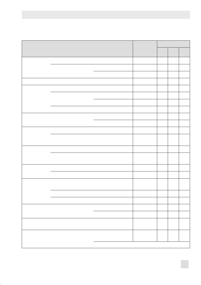
Table 1 shows the diagnostic functions and
their statements on the condition of the valve
depending on the type of application.
EB 8389-1S EN 11
Page 12

Description
Description
Table 1: Diagnostic functions and test analysis
Control
Diagnostic functions
valve
Monitoring
Data logger • • Depending on trigger status
Valve signature •
On/off valve – • − Breakaway time
Valve position
histogram
Set point deviation
histogram
Cycle counter
histogram
Leakage sensor • • − Seat leakage u 9 on page 53
Course of end
position
Dynamic tests
Valve dead band • • − Dead band u 11 on page 69
Partial stroke test
(PST)
Full stroke test (FST) • • − Overshooting
• Full scope of functions
U Function is performed, but not analyzed
– Function is not performed
On/off
valve Assessment See section
selected
U
− Change in friction
− Supply pressure
− Defective actuator springs
− Pneumatic leakage
− Transit time
− Valve end position
•
U
− Change in manipulated variable
range
− Manipulated variable range
• • − Manipulated variable range
limitation
− Seat leakage
− Positioner-valve linkage
− Average set point deviation
• • − Packing leakage
− Dynamic stress factor
• • − Course of end position
− Zero shift
• • − Overshooting
− Dead time
− T86
− Settling time
− Dead time
− T86
− Settling time
u 3 on page 21
u 4 on page 27
u 5 on page 37
u 6 on page 41
u 7 on page 44
u 8 on page 49
u 10 on page 67
u 12 on page 73
u
13 on page 83
12 EB 8389-1S EN
Page 13

Monitoring
2 Monitoring
2.1 Status messages
The valve diagnostics integrated into the po-
sitioner generates classied status messages.
Messages generated from the analysis of the
diagnosis can be classied according to the
possible causes. See u Section 4 to 13.
The following classications are possible:
− No message
If an event is classied as “No message”,
this event does not have any affect on the
condensed state.
− Function check
Test or calibration procedures are performed in the positioner. The positioner is
temporarily unable to perform its control
task as long as the procedure is taking
place.
− Maintenance request/maintenance re-
quired
The positioner still performs its control
task (with restrictions). A maintenance
demand or above average wear has
been determined. The wear tolerance will
soon be exhausted or is reducing at a
faster rate than expected. Maintenance is
necessary in the medium term.
− Out of specication
The positioner is running outside the
specied operating conditions.
− Failure
The positioner cannot perform its control
task due to a functional fault in the positioner itself or in one of its peripherals or
an initialization has not yet been successfully completed.
You can view these messages in TROVIS-
VIEW4 in the Diagnostics folder (> Monitor-
ing) and its subfolders. The 'Positioner status', 'Valve status', 'Actuator status' and
'Valve position status' messages provide a
condensed state of the status messages of
each subfolder.
2.1.1 Resetting status messages
When a status message is generated, you
should rst locate the source of the fault and
take action to remedy it.
For recommended action concerning the sta-
tus messages see u Section 17.2.
Status messages can be reset individually or
using the reset function. Table 2 on page
15 contains an overview on how the diagnosis can be reset. Resetting is performed
in the Diagnostics folder (> Service/maintenance > Reset).
If you want to keep measured data and the
analysis after resetting the positioner, it is
possible to upload them onto a computer.
Resetting single status messages
− Status messages represented by a code
in the positioner can be conrmed at the
positioner itself. Select the error code
and conrm it by pushing the rotary
pushbutton. See the standard instructions
of the positioner u EB 8384-6S EN.
− On resetting histograms and diagrams,
the data for short-term monitoring are
also reset.
EB 8389-1S EN 13
Page 14

Monitoring
− Resetting measured data does not cause
the diagnostic parameters and reference
value to be reset as well.
− The positioner does not need to be re-ini-
tialized after resetting.
Reset measured diagnostic data
Code 36 - Diag
− Parameters are reset as described in u
Section 17.4.
− Resets diagnostics assessment.
− Reference values remain unchanged.
− Status classication and data logs re-
main saved.
− The positioner does not need to be re-ini-
tialized after resetting.
− If the diagnostic data are to be reset at
regular intervals, enter the time in "Desired time until ‘Reset measured diagnostic data" (Code 48 - h3). The setting
"00:00:00" causes the resetting at regular intervals to be deactivated.
Reset start-up parameters
Code 36 - Std
− Parameters are reset as described in
u Section 17.4.
− Resets diagnostics assessment.
− Reference values are deleted.
− Status classication remains unchanged.
− Data logs are reset.
− The positioner must be re-initialized after
resetting.
Reset to default settings
Code 36 - DS
− Parameters are reset as described in
u Section 17.4.
− Resets diagnostics assessment.
− Reference values are deleted.
− Status classication and data logs are
deleted.
− The positioner must be re-initialized after
resetting.
Note:
Before mounting the positioner on a
new control valve, perform a reset by
selecting the command 'Reset to de-
fault settings' (Code 36 - DS) and re-
initialize the positioner.
14 EB 8389-1S EN
Page 15
Monitoring
Monitoring
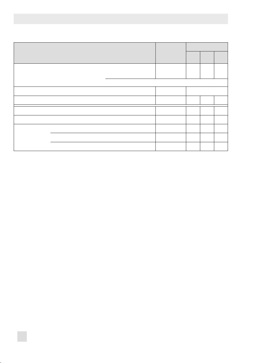
Table 2: Resetting the diagnosis
Resetting
single status
messages
Reference
graphs
Data logger Conguration and measured values NO YES YES YES
Valve signature Signal pressure(x) Measured values YES YES YES YES
On/off valve Conguration YES NO YES YES
Valve position x histogram Measured values YES YES YES YES
Set point deviation e histogram Measured values YES YES YES YES
Cycle counter histogram Measured values YES YES YES YES
Leakage sensor Short-term monitoring 'Sensitivity sound level'
Course of lower end position Measured values YES YES YES YES
Valve dead band Conguration and
Partial stroke test (PST) Conguration and
Valve signature NO NO YES YES
Leakage sensor Manufacturer reference YES NO YES YES
Process reference YES NO YES YES
Course of supply pressure Conguration NO NO YES YES
Measured values YES YES YES YES
Friction(x) Measured values YES YES YES YES
Measured values YES YES YES YES
Short-term monitoring 'Sampling time' and
measured values
Short-term monitoring 'Sampling time' and
measured values
Short-term monitoring Measured values YES YES YES YES
and measured values
Long-term monitoring Measured values YES YES YES YES
Sound level(x) Measured values YES YES YES YES
Reference value YES NO YES YES
measured values
measured values
* Except for 'Sampling time' parameter
YES YES YES YES
YES YES YES YES
YES YES YES YES
YES YES YES YES
YES NO* YES YES
Code 36
Diag Std DS
EB 8389-1S EN 15
Page 16
Monitoring
Resetting
single status
messages
Full stroke test (FST) Conguration and
measured values
* Except for 'Sampling time' and 'Max. test duration' parameters
Alarm settings NO See uSec.17.4
Status classication according to NAMUR107 NO NO NO YES
All logged messages, see u Section 2.2 YES NO YES YES
Operating hours counter NO NO NO NO
Device in operation NO NO YES YES
Device switched on since initialization NO NO YES YES
Device in operation since initialization NO NO YES YES
YES NO* YES YES
Code 36
Diag Std DS
16 EB 8389-1S EN
Page 17
Monitoring
2.1.2 Condensed state
To provide a better overview on the condition of the positioner, all status messages are
summarized in a condensed state which is
made up from a summary of all classied
messages in the positioner. The status message with the highest priority determines
which condensed state is set.
The condensed state appears in TROVIS-
VIEW4 on the right-hand side of the info
bar and in the Measured process values
folder. See u Table 3 for a description of the
icons and their meaning.
Additionally, the condensed state can be
used to trigger the data logger. See uSection 3.2.1.
Note:
The condensed state is marked by
until the positioner data have been uploaded.
The condensed state can be read in the positioner display in Code 48 - d6. See u Table
3.
Condensed state at the fault alarm output
The condensed state also be read out at the
fault alarm output if one of the following
conditions occurs:
1. Condensed state 'Failure' is activated.
2. Condensed state 'Function check' is activated and the fault alarm output is activated.
3. Condensed state 'Maintenance required'
or 'Out of specication' is activated and
the fault alarm output is activated.
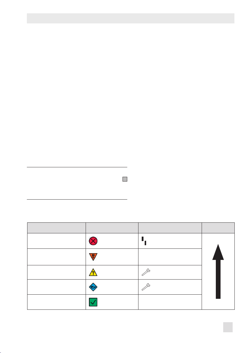
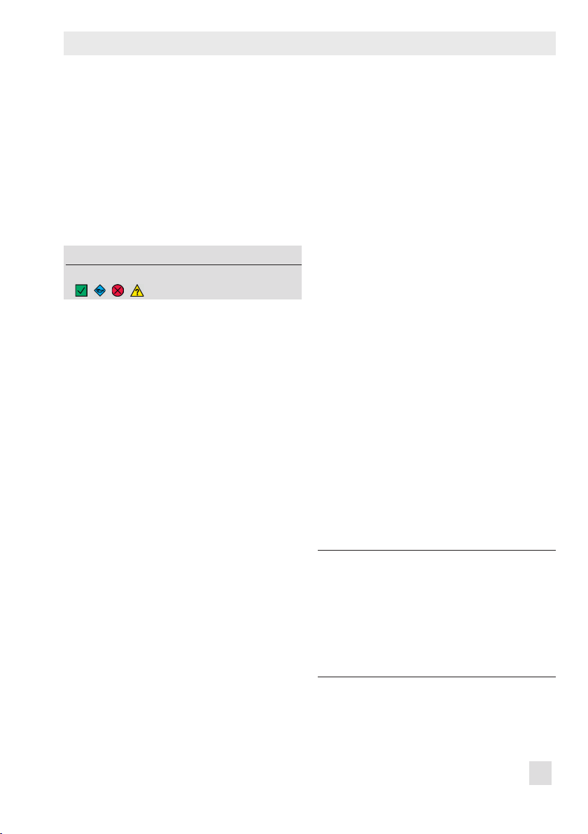
Table 3: Condensed state reading
Status message TROVIS-VIEW 4/DTM Positioner Priority
Failure
Function check
Out of specication
Maintenance request/
maintenance required
No message, OK
EB 8389-1S EN 17
red
orange
yellow
blue
green
Text e.g. TESTING, TUNE or
TEST
blinking
Page 18

Monitoring
Device settings > Alarm settings
− Fault alarm at condensed state 'Function
2.
check' (Code 32): Yes
3. − Error message in case of 'Maintenance re-
quired' and 'Out of specication' con-
densed states (Code 33): Yes
2.2 Logging
The last 30 generated messages are saved in
the positioner with a time-stamp (logged by
the operating hours counter) and with details
on how long the message exists.
You can view these messages in TROVISVIEW4 in the Diagnostics folder (> Monitor-
ing > Logging).
Logging starts automatically 15 minutes after
initialization. It does not need to be activated
by the user.
Messages are logged when:
− Their status classication is not 'No mes-
sage'.
− Their recording in the logging is activat-
ed.
− The 'Internal solenoid valve/forced vent-
ing/supply pressure' message is only additionally logged when the time entered
in 'Min. interval for new logging of internal solenoid valve' has elapsed between
the generation of two 'Internal solenoid
valve/forced venting/supply pressure'
messages.
Note:
Logging can only be deactivated when
the associated status classication is
set to 'No message'.
Device settings > Alarm settings > Status
classication > Logging
− Supply pressure: [Yes], No
− Change in friction: [Yes], No
− Seat leakage: [Yes], No
− Packing leakage: [Yes], No
− Pneumatic leakage: [Yes], No
− Defective actuator springs: [Yes], No
− Manipulated variable range limitation: [Yes],
No
− Course of end position: [Yes], No
− Positioner-valve linkage: [Yes], No
− Manipulated variable range: [Yes], No
− Change in manipulated variable range: [Yes],
No
− Partial stroke test (PST) [Yes], No
− Full stroke test (FST): [Yes], No
− On/off valve: [Yes], No
− Code 50-58, 61, 63, 76, 81: [Yes], No
− Binary input: [Yes], No
− Data logger: [Yes], No
− Internal solenoid valve/forced venting/supply
pressure: [Yes], No
− Min. interval for new logging of internal
solenoid valve: 0 to 5000 s, [300 s]
18 EB 8389-1S EN
Page 19

The following messages are not logged if
they are generated due to a hardware error:
− Packing leakage
− Pneumatic leakage
− Manipulated variable range limitation
− Course of end position
− Positioner-valve linkage
− Manipulated variable range
− Change in manipulated variable range
In this case, only the original hardware error
is logged:
− x > range (Code 50)
− Internal solenoid valve/forced venting/
supply pressure (Code 54)
− Transit time not reached (Code55)
− Inconsistent data memory (Code 59)
− Internal device error (Code 60)
− x signal (Code 62)
− i/p converter (Code 64)
− Hardware (Code 65)
Monitoring
EB 8389-1S EN 19
Page 20

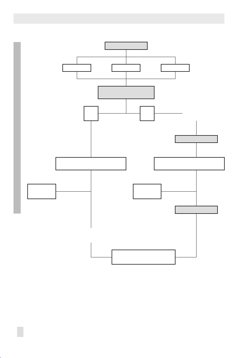
Monitoring
Data logger
â â
Permanent Triggered
â â
Sampling time
â
Start
START-UP
â
100 measured val-
(w, x, e, p
Function
1)
â â â â â
Con-
densed
state
â â â
Trigger condition
ues
) â
out
Triggered by
, x, e
w
or p
out
Trigger value
Trigger band
Trigger condition
Trigger lead time
Sampling time
Start
Solenoid
BE
valve/
forced
venting
w or solenoid
valve/forced
venting
Trigger value
Trigger band
Trigger condition
â
1)
â
Trigger event
â
Logged by operating hours
counter
â â
PROCESS
Measured values (w, x, e, pout) before trigger
event
(Number = Trigger lead/Sampling time)
Measured values (w, x, e, pout) after trigger event
+
(Number = 100 – Trigger lead/Sampling time)
â
Total 100 measured values (w, x, e, pout)
1)
The data logger is started by the software, e.g. TROVIS-VIEW 4
20 EB 8389-1S EN
Page 21
Data logger
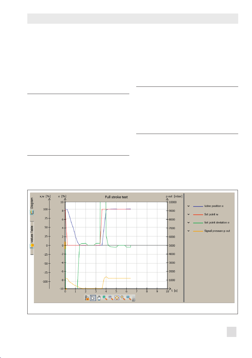
3 Data logger
The data logger records the measured variables (valve position x, set point w, set point
deviation e and signal pressure p
corded data are plotted against time in a
graph.
Note:
The data logger is interrupted and
must be reactivated when one of the
following events occurs:
−
Failure of power supply of the positioner
−
Failure of power supply of the external solenoid valve
). The re-
out
3.1 Permanent data logging
The measured variables are logged at the
rate dened in 'Sampling time' and saved in
a circular buffer, which holds 100 data
points per measured variable at one time.
Note:
You can read the measured data
logged over the past 24 hours from
the 'Data logger' graph when the Diagnostics folder (> Data logger) is left
open over this period.
Fig. 1: Diagnostics > Data logger
EB 8389-1S EN 21
Page 22

Data logger
Dening parameters
1. Select 'Permanent' (Function).
2. Enter sampling time.
3. Start data logger.
The 'Test information' status indicates
'Test active'.
Diagnostics > Data logger
1.
− Function: [Permanent]
2. − Sampling time: 0.2 to 3600.0 s, [1.0 s]
3. − Start data logger
Note:
Right-click 'Cancel data logger' and
select 'Execute' to stop the data logger
('Test information' = 'Test not active').
3.2 Triggered data logging
Measured values are saved in a circular buf-
fer after the event dened in 'Triggered by'
has occurred (see u Section 3.2.1 to 3.2.5).
The event that has triggered data logging is
recorded. Data logging is terminated after
100 measured values per measured variable
have been saved in the circular buffer. The
'Sampling time' determines the time between
recordings. A 'Trigger lead time' greater
than 0 also leads to the measuring values
before the triggering event for the time selected being included in the 100 measured
values per measured variable. The 'Trigger
lead time' may include the value 100 x
'Sampling time' at the maximum.
Dening parameters
1. Select 'Triggered' (Function).
2. Select the triggering event.
3. Enter sampling time.
4. Start data logger.
The 'Test information' status indicates
'Test active'.
When the data logging is nished, the
Progress bar indicates 'Memory full, data
recording completed'.
Note:
Right-click 'Cancel data logger' and
select 'Execute' to stop the data logger
('Test information' = 'Test not active').
3.2.1 Triggered by condensed
state
The measured values are included in the triggered event when the condensed state dened in 'Triggered by condensed state' arises.
Note:
If 'Function check' is selected as the
condensed state ('Triggered by condensed state'), data are logged when
a dynamic test starts. Data from each
test start are logged.
Diagnostics > Data logger
1.
− Function: Triggered.
2. − Sampling time: 0.2 to 3600.0 s, [1.0 s]
3. − Triggered by: Condensed state
22 EB 8389-1S EN
Page 23
Data logger
rigger band
gg
w, x, y, e
ger band
w, x, y, e
rigger band
rigger band
w, x, y, e
− Trigger lead time:
0.0 s to 100 x 'Sampling time', [20.0 s]
− Triggered by condensed state: No message,
Function check [Maintenance required],
Maintenance demanded, Out of specication, Failure
4. − Start data logger
3.2.2 Triggered by set point,
valve position, set point
deviation or signal pressure
The measured values are included in the triggered data logging when the conditions for
the selected measured variable (set point w,
valve position x, set point deviation e or signal pressure p
'Trigger band' and 'Trigger condition' are
met.
'Trigger condition' = Decreasing signal/
lower band value undercut
) dened in 'Trigger value',
out
'Trigger condition' = Increasing signal/
upper band value exceeded
Upper band limit =
Trigger value
Trigger value
Trigger band
+ ½ Trig
The conditions for starting a trigger event
are met when the value falls below the limit
('Trigger value' – ½ 'Trigger band').
'Trigger condition' = Band exit
Upper band limit =
Trigger value + ½ T
Trigger value
Lower band limit =
Trigger value - ½ T
Trigger band
Trigger value
Lower band limit =
Trigger value – ½ T
er band
Tri
The conditions for starting a trigger event
are met when the value falls below the limit
('Trigger value' – ½ 'Trigger band') or exceeds the limit ('Trigger value' + ½ 'Trigger
band').
The conditions for starting a trigger event
are met when the value falls below the limit
This function is only active when 'Trigger
band' ≠ 0.
('Trigger value' – ½ 'Trigger band').
EB 8389-1S EN 23
Page 24

Data logger
ger band
w, x, y, e
'Trigger condition' = Band entry
Upper band limit =
Trigger value
Trigger value
Lower band limit =
Trigger value - ½ Trigger band
Trigger band
+ ½ Trig
The conditions for starting a trigger event
are met when the value exceeds the limit
('Trigger value' – ½ 'Trigger band') or falls
below the limit ('Trigger value' + ½ 'Trigger
band').
This function is only active when 'Trigger
band' ≠ 0.
Diagnostics > Data logger
1.
− Function: Triggered
2. − Triggered by: Valve position, set point devi-
ation, signal pressure or set point
− Trigger value:
0.0 to 100.0 %, [99.0 %] (set point, valve
position, set point deviation)
0.0 to 7000.0 mbar, [99.0 mbar] (signal
pressure)
− Trigger band:
0.0 to 100.0 %, [99.0 %] (set point, valve
position, set point deviation)
0.0 to 10000.0 1/s, [99.0 1/s] (drive signal)
− Trigger lead time:
0.0 s to 100 x 'Sampling time', [20.0 s]
− Trigger condition: [Decreasing signal/lower
band value undercut], Increasing signal/up-
per band value exceeded, Band exit, Band
entry
3. − Sampling time: 0.2 to 3600.0 s, [1.0 s]
4. − Start data logger
3.2.3 Triggered by binary input
This setting is only active when a binary input is installed in the positioner. If this is not
the case, the Progress bar indicates 'Cannot
start data logger – trigger cannot be set'.
The measured values are included in the triggered data logging when the state of the binary input changes.
Diagnostics > Data logger
1.
− Function: Triggered
2. − Triggered by: Binary input
− Trigger lead time:
0.0 s to 100 x 'Sampling time', [20.0 s]
3. − Sampling time: 0.2 to 3600.0 s, [1.0 s]
4. − Start data logger
24 EB 8389-1S EN
Page 25

Data logger
3.2.4 Triggered by internal solenoid valve/forced
venting
This setting is only active when an internal
solenoid valve/forced venting is installed in
the positioner. See 'Internal solenoid valve/
forced venting' reading. If this is not the
case, the Progress bar indicates 'Cannot start
data logger – trigger cannot be set'.
The measured values are included in the triggered data logging when the solenoid valve
is triggered or the forced venting is activated.
Diagnostics > Data logger
1.
− Function: Triggered
2. − Triggered by: Internal solenoid valve/
forced venting
− Trigger lead time:
0.0 s to 100 x 'Sampling time', [20.0 s]
3. − Sampling time: 0.2 to 3600.0 s, [1.0 s]
4. − Start data logger
tions dened in 'Triggered by internal solenoid valve/forced venting“ or 'Triggered by
set point' are met.
Diagnostics > Data logger
1.
− Function: Triggered
− Triggered by: Set point or internal solenoid
valve/forced venting
− Trigger value: 0.0 to 100.0 %, [99.0%]
− Trigger band: 0.0 to 100.0 %, [99.0 %]
− Trigger lead time:
0.0 s to 100 x 'Sampling time', [1.0 s]
− Trigger condition: [Decreasing signal/lower
band value undercut], Increasing signal/up-
per band value exceeded, Band exit, Band
entry
3. − Sampling time: 0.2 to 3600.0 s, [20.0 s]
4. − Start data logger
3.2.5 Triggered by set point or
internal solenoid valve/
forced venting
This setting is only active when an internal
solenoid valve/forced venting is installed in
the positioner. See 'Internal solenoid valve/
forced venting' reading. If this is not the
case, the Progress bar indicates 'Cannot start
data logger – trigger cannot be set'.
The measured values are included in the triggered data logging when one of the condi-
EB 8389-1S EN 25
Page 26
Data logger
Valve signature
Requirements:
– Actuator: Single-acting
– Type of application: Control valve
Only applies to rst start-up after reset with Code 36 –
DS or Std.
â
Initialization including valve signature
â à
Start initialization
â
Valve signature recording
â
START-UP
Valve signature, signal pressure(x) Course of supply pressure Valve signature, friction(x)
â â
Alarm settings Recording threshold
Alar
â
m settings
ATC ATO and ATC
Zero limit,
lag time
Lower limit Upper limit
Status classication (NE 107) Status classication (NE 107) Status classication (NE 107)
Zero
x0 >
(ZP
+ Zero limit)
Init
x0 < (– Zero limit)
Spring pre-load
-
ing
Reduced spring
pre-loading
essure Change in friction
Supply pr
Not
available
Too low
Perm.
Too high
limit
exceeded
â â â â â â
Analysis (NE 107)/logged by
operating hours counter
PROCESS
Zero
Defective actuator
springs
Analysis (NE 107)/logged by
operating hours counter
Analysis (NE 107)/logged by
operating hours counter
Supply pressure status Change in friction
Min. supply pressure
Max. supply pressure
Dwell time (supply pressure
< 1.0bar)
l time (supply pressure
Dwel
> 7.0bar)
Valve signature
canceled
Not successful
â
Lower in total range
Lower/higher in mid-
position
Lower/higher near
max. OPEN position
Lower/higher near
CLOSED position
â
R
eset 'Pressure sensor monitoring values'
26 EB 8389-1S EN
Page 27
Valve signature
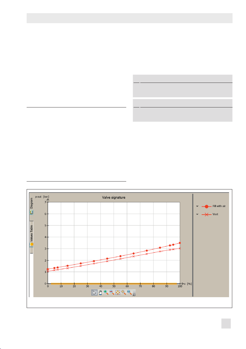
4 Valve signature
The valve signature plots the signal pressure
p
as a function of valve position x.
out
All diagnostic functions dependent on the
signal pressure are based on the valve signature, e.g. to detect pneumatic leakage or
to reveal an excessively high or low supply
pressure.
Note:
Additionally, the pneumatics are monitored using the 'Leakage limit' param
eter, which is adjustable between 0
and 100% in the Device settings fold-
er (> Alarm settings). The positioner
generates the 'Pneumatic leakage'
message whenever the leakage ex
ceeds this limit value. 'No message' is
assigned by default.
Requirements
1. A single-acting actuator is mounted on
the valve.
2. The valve operates as a control valve.
Device settings > Actuator
1.
− Principle of operation (Code 48 - d11):
Single-acting
Start-up
2.
− Type of application (Code 49 - h0):
Control valve
-
To perform monitoring while the process is
running, the reference graph must rst be
plotted.
-
Fig. 2: Start-up > Reference graphs > Valve signature
EB 8389-1S EN 27
Page 28

Valve signature
4.1 Reference graphs
During the plotting of the reference graph
(Fig. 2), the valve is moved very slowly from
the end position at which no pressure is applied to the actuator to the position at which
the maximum air signal is applied to the actuator. The valve is then moved back again
to its end position. During which, the positioner switches to open-loop control (control
without feedback).
The sensitivity of reference graph plotting de-
nes at which speed the valve is moved. The
time span how long the reference graph is to
be plotted depends on the sensitivity select-
ed. Select 'High' for valves with small bench
ranges and/or high friction.
After the reference graph has been plotted,
the recorded data points for signal pressure
p
and valve position x are converted into
out
xed points.
Note:
The valve positions cannot be predicted in open-loop control (control without feedback). The reference graph
may differ for the same valve after
each logging.
Dening parameters
The reference graph is automatically plotted
after initialization when 'Initialization including valve signature' = Yes.
Start-up
− Initialization including valve signature
(Code 48 - h0): [Yes]
The reference graph can also be plotted separately outside initialization.
1. Switch to manual mode.
2. Select 'Sensitivity' from the drop-down
list.
3. Start test.
The 'Test information' status indicates
'Test active'. 'D1' and 'TEST' are indicat-
ed in alternating sequence on the positioner display.
'Function check'
is activated as the
condensed state.
Start-up
1.
− Enter operating mode (Code 0): Manual
2.Start-up > Reference graphs > Valve
signature
− Sensitivity: Low, [Medium], High
3. − Start test
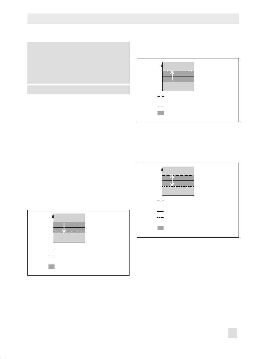
4.1.1 Analysis and monitoring
The positioner records the data for lling and
venting the actuator. It then determines the
characteristic values listed below:
− 'Mean hysteresis': Average hysteresis
(average signal pressure change Δp
relation to the spring range)
− 'Min. hysteresis': Lowest possible hystere-
sis (minimum signal pressure change
Δp
in relation to the spring range)
out
− 'Max. hysteresis': Highest possible hys-
teresis (maximum signal pressure change
Δp
in relation to the spring range)
out
in
out
28 EB 8389-1S EN
Page 29
Valve signature
− 'Detected lower spring range value': Sig-
nal pressure p
lled with the minimum amount of air
− 'Detected upper spring range value': Sig-
nal pressure p
lled with the maximum amount of air
The 'Valve signature canceled' message is
generated if the test is canceled.
Start-up > Initialization result
− Valve signature canceled (Code 81):
, , ,
The 'Test status' reading indicates the reason
why the test was canceled:
− No supply pressure: The supply pressure
was under 500mbar during the test.
− Valve moved too quickly. Recommended
action: Increase sensitivity
− Position at p
air):
(1) Even though the pressure was in-
creased in steps from 0bar to the maximum amount of air for lling the actua-
tor, the valve was not able to reach the
maximum position in closed-loop operation.
(2) The minimum valve position without
tight-closing is below 96%.
Recommended action: Increase supply
pressure.
− Position at p
(1) Even though the pressure was reduced in steps from the maximum
amount of air for lling the actuator, the
valve was not able to reach the minimum
when the actuator is
out
when the actuator is
out
not reached (lling with
max
not reached (venting):
min
position in closed-loop operation. The
valve might be jammed.
(2) The minimum valve position without
tight-closing is above 4%.
− Time-out
− Double-acting actuator
− Internal error
− Current too low
− Internal solenoid valve/forced venting
triggered
− SUB initialization
4.2 Valve signature, signal
pressure(x)
The positioner records the data for lling and
venting the actuator during closed-loop operation. The recorded data can be directly
compared with the reference graph. Additionally, the minimum, maximum and current
supply pressure are shown in the graph.
Data are recorded in the background regardless of the operating mode selected if a
reference graph has already been plotted.
Data logging does not need to be activated.
Note:
The positioner determines the minimum and maximum supply pressure
while plotting the reference graph. The
current supply pressure may fall below
the minimum supply pressure and exceed the maximum supply pressure.
Dening parameters
1. Record reference graph. u Section 4.2.
EB 8389-1S EN 29
Page 30

Valve signature
2. Set the limit for zero monitoring in control valves with closed position ATC (air
to close).
3. Select classication for status messages.
See u Section 4.2.1.
Device settings > Alarm settings
2.
− Zero limit (Code 48 - d5):
0.0 to 100.0 %, [5.0 %]
− Lag time: 1 to 9999 s, [30 s]
3.Device settings > Alarm settings > Status
classication > Positioner
− Zero (Code 58):
Device settings > Alarm settings > Status
classication > Actuator
Defective actuator springs
− Reduced spring pre-loading:
, [ ], ,
[ ], , ,
4.2.1 Analysis and monitoring
If the monitoring line has a smaller gradient
than the reference line, this pinpoints to a reduced compression of the actuator springs.
Diagnostics > Monitoring > Actuator
− Defective actuator springs:
Valves with ATC (air to close) closed position
In valves with ATC closed position, the positioner generates a zero error when the valve
position in the tight-closing position is larger
than the sum of the initialization zero points
and 'Zero limit' or smaller than the negative
'Zero limit' after the adjusted 'Lag time' has
elapsed.
Diagnostics > Monitoring > Positioner
− Zero (Code 58):
, , ,
, , ,
Fig. 3: Diagnostics > Monitoring/tests > Valve signature > Valve signature, signal pressure(x)
30 EB 8389-1S EN
Page 31

Valve signature
4.3 Course of supply pressure
During control-loop operation, ve values of
the supply pressure are recorded and saved
in a circular buffer. A new supply pressure is
recorded and saved in the circular buffer
when it deviates from the last value plotted in
the graph by the amount entered in 'Recording threshold'.
Data are recorded in the background regardless of the operating mode selected. Data logging does not need to be activated. To
monitor the limits ('Lower limit' and 'Upper
limit'), the corresponding limit must be activated rst. The limits are automatically deter-
mined while the valve signature is being
plotted. Alternatively, user-dened limits can
be entered.
Dening parameters
1. Dene 'Recording threshold'.
2. Enter limits for monitoring. See u Section 4.3.1.
3. Select classication for status messages.
See u Section 4.3.1.
1.Diagnostics > Monitoring/tests > Valve
signature > Course of supply pressure
− Recording threshold:
0.10 to 14.00 bar, [0.50 bar]
Device settings > Alarm settings
2.
− Activate lower limit: [Yes], No
− Lower limit: [0.0] to 7.0 bar
− Activate upper limit: Yes, [No]
− Upper limit: [0.0] to 7.0 bar
Fig. 4: Diagnostics > Monitoring/tests > Valve signature > Course of supply pressure
EB 8389-1S EN 31
Page 32

Valve signature
3.Device settings > Alarm settings > Status
classication > Supply pressure
− Permissible limit exceeded:
, , , [ ]
− Too high: , [ ], ,
− Fluctuates: [ ], , ,
− Too low: , [ ], ,
− Not available: , , , [ ]
4.3.1 Analysis and monitoring
The positioner generates the 'Supply pressure status' message with the dened status
classication.
− 'Too high' if the supply pressure exceeds
the 'Upper limit'.
− 'Not available' if the supply pressure falls
below 0.1bar.
− 'Too low' if the supply pressure exceeds
the 'Lower limit'.
− 'Permissible limit exceeded' if the supply
pressure exceeds 7.0bar.
A uctuating supply pressure is recognized
by the positioner whenever the supply pres-
sure continuously falls below the 'Lower limit'
and rises above the 'Upper limit'. In such
cases, the positioner generates the 'Supply
pressure status' message with the dened
status classication.
− Min. supply pressure
− Time stamp of min. supply pressure
− Max. supply pressure
− Time stamp of max. supply pressure
− Dwell time (supply pressure < 1.0 bar)
− Dwell time (supply pressure > 7.0 bar)
Diagnostics > Monitoring > Actuator
− Supply pressure status:
− Supply pressure (Code 48 - d7)
, , ,
32 EB 8389-1S EN
Page 33

Valve signature
4.4 Valve signature, friction(x)
The positioner calculates the friction during
closed-loop operation and compares it with
the friction determined when the reference
graph was plotted.
Data are recorded automatically 15 minutes
after initialization (regardless of the operating mode selected) if a reference graph has
already been plotted. Data logging does not
need to be activated.
Dening parameters
1. Record the reference graph. See u Section 4.1.
2. Select classication for status messages.
See uSection 4.2.1.
2.Device settings > Alarm settings > Status
classication > Valve
Change in friction
− Higher in total range: [
− Lower in total range: [ ], , ,
− Higher in mid-position: [ ], , ,
− Lower in mid-position: [ ], , ,
− Higher near max. OPEN position:
[ ], , ,
− Lower near max. OPEN position:
[ ], , ,
− Higher near CLOSED position:
[ ], , ,
− Lower near CLOSED position:
[ ], , ,
], , ,
Fig. 5: Diagnostics > Monitoring/tests > Valve signature > Valve signature, friction(x)
EB 8389-1S EN 33
Page 34

Valve signature
4.4.1 Analysis and monitoring
The positioner generates the 'Change in friction' message with the selected status classi-
cation. The friction for the total range of the
valve, the mid valve position and for the
ranges near to the end positions are compared.
The positioner calculates the friction during
closed-loop operation from the actuator lling and venting graphs at the point where a
directional change in valve travel takes
place. The positioner converts the friction data into xed points close to the point of directional change and compares them to the
reference friction.
If the friction at a xed point increases to
more than double of the reference friction,
the friction is regarded to be higher.
If the friction at a xed point drops to less
than half of the reference friction, the friction
is regarded to be lower.
Note:
To ensure that sufcient data points
are available for calculating the friction, the valve must not be moved too
quickly.
4.5 Resetting single status messages
All messages generated by the valve signature can be reset together by selecting and
executing "Reset 'Pressure sensor monitoring
values". These messages include:
− Change in friction
− Supply pressure status
− Defective actuator springs
− Zero
At the same time, the supply pressure data
(supply pressure, min. supply pressure and
max. supply pressure) are reset as well.
Diagnostics > Service/maintenance > Reset
− Reset 'Pressure sensor monitoring values'
Diagnostics > Monitoring > Valve
− Change in friction:
34 EB 8389-1S EN
, , ,
Page 35

Page 36

Valve signature
On/off valve
START-UP
Prerequisite:
– Type of application: On/off valve
â
Operating point, Limit fail-safe position, Limit operating point
â
Travel time assessment limit
Valve end position limit
Status classication (NE 107)
Breakaway time increasing/decreasing
Transit time increasing/decreasing
Final travel/angle value not reached
Final travel/angle value increasing/
easing
decr
â â
On/off diagnosis Discrete set point analysis PST
Dene parameters for partial stroke
test, see u Section 12
â
First analysis after dening parameters =
Breakaway time, transit
time, valve end position
(increasing/decreasing)
logged by operating hours counter
PROCESS
Reset measured 'On/off valve' values
Reset all 'On/off valve' parameters
Reference
â â
Analysis (NE 107)/
On/off valve status
â
Analysis, see
u Section 12.3
36 EB 8389-1S EN
Page 37

On/off valve
Operating point limit
Fail-safe action limit
x [%]
Operating point limit
Fail-safe action limit
x [%]
Lower range value (PST)
Upper range value (PST)
x [%]
5 On/off valve
The travel range of open/close (on/off) is
dened by the fail-safe position and the operating point. As a result, the following parameters to determine the working range
and set point range are not analyzed and
cannot be changed.
− Lower travel/angle range value
− Upper travel/angle range value
− Lower travel/angle limit
− Upper limit for travel/angle
− Lower set point range value
− Upper set point range value
The discrete analysis of the reference variable is performed in automatic mode.
If the set point ( ) is below 'Operating point
limit' when the automatic mode starts, the
valve (
the set point increases and exceeds 'Operating point limit', the valve moves to the 'Operating point'. The valve moves back to the
fail-safe position (0% in the example) if the
set point then falls below 'Fail-safe action
limit'.
) moves to the fail-safe position.
w [%]
Operating point
If
If the set point ( ) is above 'Operating
point limit' when the automatic mode
starts, the valve (
) moves to the operating
point. The valve moves back to the fail-safe
position (0% in the example) if the set point
then falls below 'Fail-safe action limit'.
w [%]
Operating point
50
25
Fail-safe position
t <6s
t [s]
Starting the partial stroke test (PST)
A partial stroke test is started when the set
point ( ) moves in the range between 25
and 50% of the travel range and remains
there for longer than six seconds. See
uSection 12.1.
w [%]
Operating point =
Operating point limit
Stop PSTStart PST
50
25
>6s
t
t [s]
Fail-safe position
50
25
∆t > 6 s
Fail-safe action limit
Fail-safe position
t [s]
EB 8389-1S EN 37
Page 38

On/off valve
The PST diagnostic parameter 'Lower range
value' must be within the dened position ±
'Tolerance limit' for the partial stroke test to
start.
After the partial stroke test is completed, the
valve moves back to its last position (fail-safe
position or operating point).
Canceling the partial stroke test (PST)
The partial stroke test is canceled whenever
the set point (
'Fail-safe action limit' and 'Operating point
limit', falling below 'Operating point limit'.
After the partial stroke test is canceled, the
valve moves back to its last position (fail-safe
position or operating point).
Dening parameters
Note:
The parameters can only be dened in
TROVIS-VIEW4 after the 'Type of ap-
plication' has been set to 'On/off
valve'.
1. Select the type of application.
2. Dene parameters for on/off valve.
3. Dene parameters for partial stroke test
(PST). See u Section 12.
Start-up
1.
− Type of application (Code 49 - h0): On/off
valve
2.Device settings > Positioner > Transfer
characteristic on/off
− Operating point (Code 49 - h1): 0.0 to
100%, [100 %]
) leaves the range between
− Fail-safe action limit (Code 49 - h2): 0.0 to
20.0 %, [12.5 %]
− Operating point limit (Code 49 - h5):
55.0 to 100.0 %, [75.0 %]
3.Diagnostics > Monitoring/tests > Dynamic
tests > Partial stroke test (PST)
See u Section 12
5.1 Diagnostics for on/off
valve
The diagnostics for on/off valve provide
statements on the valve end positions, transit
times (increasing/decreasing) and breakaway times (increasing/decreasing).
The data are recorded automatically for the
diagnostics for on/off valve in automatic
mode. Data logging does not need to be activated.
The positioner compares the current breakaway time, transit time and valve position
with the values recorded during the reference
measurement (rst analysis) while the plant is
running.
Dening parameters
Note:
The parameters can only be dened in
TROVIS-VIEW4 after the 'Type of ap-
plication' has been set to 'On/off
valve'.
1. Enter limits for monitoring. See u
5.2.
2. Select classication for status messages.
Section
38 EB 8389-1S EN
Page 39

On/off valve
(decreasing)
(increasing)
x [%]
t [s]
Device settings > Alarm settings
1.
− Travel time assessment limit (Code 49 - h7):
[0.6] to 30.0 s
− Valve end position limit (Code 49 - h8):
[0.3] to 100.0 %
2.Device settings > Alarm settings > Status
classication > On/off valve
− Increasing breakaway time: [
− Decreasing breakaway time:
[ ], , ,
− Transit time increasing: [ ], , ,
− Transit time (decreasing): [ ], , ,
− Final travel/angle value not reached:
[ ], , ,
− Increasing nal travel/angle value:
[ ], , ,
− Decreasing nal travel/angle value:
[ ], , ,
5.2 Analysis and monitoring
The analysis pinpoints to a fault when at
least one of the following conditions is met
while the valve is moving:
− The current 'Increasing breakaway time'
differs from the reference value by the
amount entered in 'Travel time assessment limit'.
− The current 'Decreasing breakaway time'
differs from the reference value by the
amount entered in 'Travel time assessment limit'.
− The current 'Transit time increasing' dif-
fers from the reference value by the
amount entered in 'Travel time assessment limit'.
], , ,
− The current 'Transit time (decreasing)' dif-
fers from the reference value by the
amount entered in 'Travel time assessment limit'.
− The current 'Transit time increasing' dif-
fers from the reference value by the
amount entered in 'Valve end position
limit'.
− The current 'Transit time (decreasing)' dif-
fers from the reference value by the
amount entered in 'Valve end position
limit'.
− The valve end position is not reached.
w [%]
Valve end position
(increasing)
Valve end position
(decreasing)
Breakaway time
(decreasing)
Transit time
Breakaway time
(increasing)
Transit time
Fig. 6: Analysis of diagnostics for on/off valve
If one of these conditions is met, the position-
er generates an 'On/off valve status' message according the selected status classica-
tion.
Diagnostics > Monitoring
− On/off valve status (Code 85):
, , ,
EB 8389-1S EN 39
Page 40

On/off valve
5.3 Resetting single status messages
The message and the limit values are reset
by selecting and executing "Reset measured
'On/off valve' values".
The positioner saves the reference analysis
and two further test analyses. The analysis of
the oldest test is deleted when another test is
performed.
Diagnostics > Service/maintenance > Reset
− Reset measured 'On/off valve' values
40 EB 8389-1S EN
Page 41

Valve position x histogram
6 Valve position x histogram
The valve position histogram is a statistical
analysis of the plotted valve positions. The
histogram provides information about where
the valve mainly spends the majority of its
time during its service life and whether it
shows a recent trend concerning changes in
its operating range.
Data are recorded automatically 15 minutes
after initialization (regardless of the operating mode selected). Data logging does not
need to be activated.
The positioner records the valve position every second and assigns the data into predened valve position classes. The distribution showing how often the sound level occurred within a valve position class is shown
in a bar graph.
− 'Mean value': Average class assignment
of valve positions throughout 'Monitoring
duration'.
− 'Number of measurement points': Total
number of values recorded during the
'Monitoring duration'.
− 'Monitoring duration'
The measured data are saved every 24
hours in the positioner.
Short-term monitoring
In order to be able to recognize any shortterm changes in valve position, the positioner records the valve positions according to
the adjusted 'Sampling time' and analyses
the last 100 measured values.
− 'Mean time': Contains the average class
assignment of valve positions for the last
100 measured values.
− 'Adjusted monitoring duration': 100 x
'Sampling time'
The positioner saves the valve positions in a
circular buffer, which holds 100 measured
values at one time.
Fig. 7: Diagnostics > Monitoring/tests > Histograms > Valve position x histogram
EB 8389-1S EN 41
Page 42

Valve position x histogram
Note:
Changing 'Sampling time' causes all
existing measured values to be deleted from the circular buffer.
Dening parameters
1. Set the 'Sampling time' for the short-term
monitoring.
2. Select classication for status messages.
See u Section 6.1.
Diagnostics > Monitoring/tests > Histograms
> Valve position x histogram > Short-term
monitoring
1.
− Sampling time: Adjustable as required,
[00:14:24 d.h:min:s]
2.Device settings > Alarm settings > Status
classication > Valve position
Manipulated variable range
− Mainly near CLOSED position:
], , ,
[
− Mainly near max. OPEN position:
[ ], , ,
− Mainly in CLOSED position:
[ ], , ,
− Mainly near max. OPEN position:
[ ], , ,
Change in manipulated variable range:
− Operating range shifted to CLOSED
position: [ ], , ,
− Operating range shifted to max. OPEN
position: [ ], , ,
− Short-term change: [ ], , ,
6.1 Analysis and monitoring
Analysis of the histogram for control valves
starts one hour after the monitoring period
begins. No analysis is performed for on/off
valves.
If the control valve mainly works during the
monitoring duration near or in one of the
end positions, the positioner generates the
'Manipulated variable range' message with
the selected status classication.
For analysis of the short-term monitoring, a
complete set of data (100 measured values)
is required. The analysis is only active when
the sampling time setting is greater or equal
to one minute.
The positioner generates the 'Change in manipulated variable range' message with the
selected status classication whenever a
trend showing a change in the operating
range is found from the analysis of the histogram and the short-term monitoring.
Diagnostics > Monitoring > Valve position
− Manipulated variable range:
− Change in manipulated variable range: ,
, ,
, , ,
6.2 Resetting single status messages
The 'Manipulated variable range' and the
'Change in manipulated variable range'
messages can be reset by selecting and executing the command "Reset 'Reset valve position x histogram". This command resets all
diagnostic parameters and measured data
42 EB 8389-1S EN
Page 43

of the histogram and the short-term monitoring.
By selecting and executing the command
"Reset 'Short-term valve position x histo-
gram", the diagnostic parameters and measured data in the Short-term monitoring
folder are reset.
Diagnostics > Service/maintenance > Reset
− Reset 'Valve position x histogram'
− Reset 'Short-term valve position x histogram'
Valve position x histogram
EB 8389-1S EN 43
Page 44

Set point deviation e histogram
7 Set point deviation e histo-
gram
The set point deviation histogram contains a
statistical analysis of any set point deviations
recorded. It provides information on to which
extent a set point deviation has occurred
during the valve service life and whether
faults may occur due to a restricted operating range or due to seat leakage.
Data are recorded automatically 15 minutes
after initialization (regardless of the operating mode selected). Data logging does not
need to be activated.
The positioner records the set point deviation
every second and assigns the data into pre-
dened classes. The distribution showing
how often the set point deviation remained
within a class is shown in a bar graph.
− 'Mean value': Average class assignment
of set point deviation throughout 'Monitoring duration'.
− 'Number of measurement points': Total
number of values recorded during the
'Monitoring duration'.
− 'Monitoring duration'
The measured data are saved every 24
hours in the positioner.
Short-term monitoring
In order to be able to recognize any shortterm changes in set point deviation, the positioner records the set point deviation accord-
ing to the adjusted 'Sampling time' and
analyses the last 100 measured values.
− 'Mean time': Contains the average class
assignment of set point deviations for the
last 100 measured values.
− 'Adjusted monitoring duration': 100 x
'Sampling time'
The positioner saves the set point deviations
in a circular buffer, which holds 100 measured values at one time.
Fig. 8: Diagnostics > Monitoring/tests > Histograms > Set point deviation e histogram
44 EB 8389-1S EN
Page 45

Set point deviation e histogram
Note:
Changing 'Sampling time' causes all
existing measured values to be deleted from the circular buffer.
Dening parameters
1. Set the 'Sampling time' for the short-term
monitoring.
2. Select classication for status messages.
See u Section 7.1.
Diagnostics > Monitoring/tests > Histograms
> Set point deviation e histogram > Shortterm monitoring
1.
− Sampling time: Adjustable as required,
[00:14:24 d.h:min:s]
2.Device settings > Alarm settings > Status
classication > Valve
Seat leakage
− May exist: [
Device settings > Alarm settings > Status
classication > Valve position
Manipulated variable range limitation
− Lower: [
− Upper: [ ], , ,
− No change possible: [ ], , ,
Positioner-valve linkage
− Travel transmission not optimal:
[ ], , ,
], , ,
], , ,
7.1 Analysis and monitoring
Ideally, the set point deviation should be
nearly 0%.
Set point deviations greater than 1% follow-
ing in quick succession pinpoint to a limitation of the upper operating range. In this
case, the positioner generates the 'Manipulated variable range limitation' and 'Positioner-valve linkage' messages with the selected status classications.
Set point deviations smaller than 1% follow-
ing in quick succession pinpoint to a limitation of the lower operating range or to seat
leakage. The positioner generates the 'Manipulated variable range limitation', 'Positioner-valve linkage' and 'Seat leakage'
messages with the selected status classica-
tions.
If almost all set point deviations during the
short-term monitoring are greater than 1%
or smaller than –1%, this may indicated that
the actuator or valve stem is jammed. The
positioner generates the 'Manipulated variable range limitation' and 'Positioner-valve
linkage' messages with the selected status
classications.
Diagnostics > Monitoring > Valve
− Seat leakage:
Diagnostics > Monitoring > Valve position
− Manipulated variable range limitation:
, ,
− Positioner-valve linkage: , , ,
, , ,
,
EB 8389-1S EN 45
Page 46

Set point deviation e histogram
7.2 Resetting single status messages
The 'Seat leakage', 'Manipulated variable
range limitation' and 'Positioner-valve linkage' messages can be reset by selecting and
executing the command "Reset 'Set point deviation e histogram" or "Reset 'Short-term set
point deviation e histogram".
By selecting and executing the "Reset 'Set
point deviation e histogram" command, all
diagnostic parameters and measured data
of the histogram and the short-term monitoring are reset.
By selecting and executing the command
"Reset 'Short-term set point deviation e histo-
gram", the diagnostic parameters and measured data in the Short-term monitoring
folder are reset.
Diagnostics > Service/maintenance > Reset
− Reset 'Set point deviation histogram e'
− Reset 'Short-term set point deviation e histo-
gram'
46 EB 8389-1S EN
Page 47

Page 48

Set point deviation e histogram
t [s]
x [%]
t [s]
x [%]
Cycle counter histogram
Stem seal
â
â â â â
Self-adjusting Adjustable Other, -/- Bellows seal
â
Max. cycle count
START-UP
PROCESS
â â â
â â
Status classication (NE 107)
External leakage possibly to be
expected soon
â â
Determining the cycle spans
1
3
2
4
â â
Dynamic stress factor Dynamic stress factor
Dynamic stress factor > 90
%
â â
Analysis (NE 107)/
logged by operating hours counter
acking leakage
P
Status classication (NE 107)
External leakage possibly to be
expected soon
Determining the cycle height
2
1
4
3
Dynamic stress factor > 90
%
Analysis (NE 107)/
logged by operating hours counter
Packing leakage
â
Reset 'Cycle counter histogram'
48 EB 8389-1S EN
Page 49

Cycle counter histogram
8 Cycle counter histogram
The cycle counter histogram provides a statistical analysis of the cycles. As a result, the
cycle c
ounter also provides information on
the dynamic stress of a bellows seal and/or
packing.
Data are recorded automatically 15 minutes
after initialization (regardless of the operating mode selected). Data logging does not
need to be activated.
The positioner records the number of cycle
spans when the stem seal setting is set to
'Live-loaded', 'Adjustable', 'Other' or '-/-'.
A valve cycle span starts at the point where
the valve stroke changes direction until the
point where it changes direction again. The
valve stroke between these two changes in
direction is the cycle span.
The positioner records the cycle height when
the 'Stem seal’ setting is set to 'Bellows seal'.
The cycle height is the travel performed between two changes in direction.
The cycle spans or cycle heights are assigned to classes. The distribution showing
how often the cycle span or height occurred
within a class is shown in a bar graph.
− 'Mean value': Average class assignment
of cycle height calculated from the 'No.
of cycles'
− 'No. of cycles'
The measured data are saved every 24
hours in the positioner.
Dening parameters
1. Select the type of stem seal.
(*When 'Other' is selected as the stem
seal, the additional parameter 'Max. cycle count' must also be set).
Device settings > Alarm settings
1.
− Stem seal: [-/-], Live-loaded, Adjustable,
Bellows seal, Other
* − Max. cycle count:
1 to 1000000000, [1000000]
Fig. 9: Diagnostics > Monitoring/tests > Histograms > Cycle counter histogram
EB 8389-1S EN 49
Page 50

Cycle counter histogram
Short-term monitoring
To recognize short-term changes in the cycle
spans or cycle height, the positioner analyzes the last 100 cycle heights or cycle spans.
The positioner saves the cycle heights or cycle spans in a circular buffer, which holds
100 measured values at one time.
− 'Mean time': Contains the average class
assignment for the last 100 measured
values.
Dening parameters
1. Select classication for status messages.
1.Device settings > Alarm settings > Status
classication > Valve
Packing leakage
− Possibly to be expected soon: [
,
], ,
8.1 Analysis and monitoring
The load on the bellows and/or packing can
be read from the 'Dynamic stress factor' parameter. The value is determined from the cycle spans or cycle heights and takes into account the type of packing used in the valve.
A 'Packing leakage' message is generated
with the selected status classication whenev-
er:
− The number of measured cycle spans ex-
ceeds 450000 when 'Live-loaded' is selected as the stem seal.
− The number of measured cycle spans ex-
ceeds 180000 when 'Adjustable' is selected as the stem seal.
− The number of measured cycle spans ex-
ceeds 90% of the 'Max. cycle count'
when 'Other' is selected as the stem seal.
− The number of measured cycle heights
exceeds 180000 when 'Bellows seal' is
selected as the stem seal.
Measured process values
− Dynamic stress factor
Diagnostics > Monitoring > Valve
− Packing leakage:
, , ,
8.2 Resetting single status messages
The 'Packing leakage' message is reset by
selecting and executing the command "Reset
'Cycle counter histogram" or "Reset 'Short-
term cycle counter histogram".
By selecting and executing the "Reset 'Cycle
counter histogram" command, all measured
data of the histogram and the short-term
monitoring as well as the 'Dynamic stress
factor' are reset.
By selecting and executing the command
"Reset 'Short-term cycle counter histogram",
the measured data in the Short-term monitoring folder are reset.
Diagnostics > Service/maintenance > Reset
− Reset 'Cycle counter histogram'
− Reset 'Short-term cycle counter histogram'
50 EB 8389-1S EN
Page 51

Page 52

Cycle counter histogram
x [%]
t [s]
Leakage sensor
Requirements
– Positioner accessories identication:
Leakage sensor
– Activate CLOSED end position: On
â
START-UP
Manufacturer reference
with specied standard conditions
Level (x)
diagram
ß
Phase 3
â â
Reset 'Leakage sensor
manufacturer reference'
Settling time before sound level
measurement
à
Set points, sensitivity sound level
Start
ß Not successful
Phase 2
Alarm settings
Response time, preset alarm limits
Status classication (NE 107)
Alarm limit 2
exceeded
Process reference
with process conditions
User-dened
á
â
Sensitivity sound
â
level lower
á
Cancel
â
â á
ß Successful
Successful
Phase 1
Reset 'Leakage sensor process
reference'
â â
ß
Alarm limits 1,
2, 3
Recommended:
10 dB, 15 dB, 25 dB
Alarm limit 3
exceeded
Determining the mean sound levels while the
valve is tightly shut
Cyclic analysis of sensor level, e.g. over
dynamic HART® variables
0
PROCESS
Mean sound level exceeds
alarm limit 2
â â
Mean sound level exceeds
alarm limit 3
Analysis (NE 107)/logged by operating hours counter
Seat leakage
â
Reset 'Leakage sensor process reference'
52 EB 8389-1S EN
Page 53

Leakage sensor
9 Leakage sensor
By upgrading the positioner with a leakage
sensor, it is possible to detect seat leakage
when the valve is in the closed position. To
achieve this, the leakage sensor measures
the sound pressure level (dB) while the valve
is tightly shut and compares the current
sound pressure level with predened alarm
limits. The positioner generates a message if
the current sound pressure level exceeds one
of the alarm limits.
Requirements for using the seat leakage
sensor:
1. A leakage sensor is mounted to the
valve. Refer to the standard mounting
and operating instructions of the positioner uEB8384-6 EN
Alarm limit 3
2. The leakage sensor option has been selected.
3. The tight-closing function has been activated.
4. The leakage sensor has been put into operation. See u Section 9.1.
2.Start-up > Reference graphs > Leakage
sensor
− Positioner accessories identication:
Leakage sensor
Device settings > Positioner > Transfer
characteristic or Transfer characteristic on/
off
3.
− Activate CLOSED end position (Code 14):
On
− CLOSED end position (Code 14):
0.0 to 49.9 %, [1.0 %]
Alarm limit 2
Fig. 10: Start-up > Reference graphs > Leakage sensor > Manufacturer reference
Alarm limit 1
EB 8389-1S EN 53
Page 54

Leakage sensor
9.1 Start-up of the leakage
sensor
To be able to use the full scope of functions,
the response of the leakage sensor to standardized conditions and to the prevailing
process conditions must be measured. Furthermore, the limit to activate the alarm must
be entered.
9.1.1 Manufacturer reference
The manufacturer reference (u Fig. 10) measures the response of the leakage sensor. We
recommend performing the manufacturer
reference test. On request, it can also be
performed by SAMSON and must not be
performed again. In this case, the standard
conditions are:
• Medium = air
• Input pressure = 4 bar
• Output pressure = atmosphere
Default values of alarm limits are A2 = 15
dB and A3 = 25 dB. If the leakage sensor
has been tted later onto the valve, the
alarm limits must be manually congured
or adjusted by performing a manufacturer
or process reference test before the leakage
sensor can be used. See u Section 9.1.2.
While the manufacturer reference test is running, the parameters listed below are automatically deactivated:
− Activate CLOSED end position
− Activate ramp function
Phase 1: The valve moves to eleven dened
set points one after the other. After reaching
a set point and after the 'Settling time before
sound level measurement' has elapsed, the
leakage sensor measures the sound pressure
level.
If the difference between two neighboring set
points is larger or equal to the adjusted 'Sensitivity sound level', the valve does not move
to the next set points. Instead, Phase 2 starts.
Phase 1 successful: The sound pressure level
exceeded the adjusted 'Sensitivity sound level'
(10dB) between set points 4 and 5. Phase 2
starts.
If the 'Sensitivity sound level' is not reached
after the valve has moved to all eleven set
points, the test is canceled. The canceled test
is logged with a time stamp. The 'Test information' reading indicates 'Test failed: sound
level change too small'.
Phase 1 not successful: The difference in sound
pressure level between two neighboring set points
is smaller than the 'Sensitivity sound level'
(10dB). The reference test is canceled.
54 EB 8389-1S EN
Page 55

Phase 2: A 0.30 % band is placed around
the last set point that the valve moved to.
One third of this band lies in front of the set
point that the valve moved to and two thirds
of the band lies behind it. The band itself is
subdivided into eleven xed points. Each
xed point is located at a distance of 0.03%
to the next point. The valve moves to the new
xed points one after the other. After reaching a xed point and after the 'Settling time
before sound level measurement' has
elapsed, the leakage sensor measures the
sound pressure level.
The manufacturer reference test is successful
when the difference between the rst and last
newly dened points is larger or equal to the
adjusted 'Sensitivity sound level'.
Leakage sensor
Phase 2 not successful: The difference in sound
pressure level between the rst and last newly
dened points is lower than 'Sensitivity sound
level' (10 dB). Phase 3 starts.
Phase 3: The valve moves to the set points
valid for phase 1 one after the other. This is
plotted in a sound level vs. travel graph. The
graph shows where the point of activation is
and to which value the 'Sensitivity sound level' must be reduced to allow the test to be
completed successfully.
Dening parameters
Note:
The parameters can only be dened in
TROVIS-VIEW4 after the 'Positioner
Phase 2 successful: The 'Sensitivity sound level'
(10 dB) is reached between the rst and last
newly dened points. The manufacturer test is
successfully completed.
If the 'Sensitivity sound level' is not reached
after the valve has moved to all eleven newly
dened points, then the change in sound
pressure level is too low. In this case, phase
3 starts.
EB 8389-1S EN 55
accessories identication' has been set
to 'Leakage sensor'.
1. Switch to manual mode.
2. Dene the parameters for the manufacturer reference test. Refer to Note con-
cerning editing set points.
3. Start manufacturer reference test.
The start of the reference test is documented in the Time stamp.
'D8' and 'TEST' are indicated in alternating sequence on the positioner display.
Page 56

Leakage sensor
Start-up
1.
− Enter operating mode (Code 0): Manual
2.Start-up > Reference graphs > Leakage
sensor > Manufacturer reference
− Settling time before sound level measure-
ment: 1 to 255 s, [5 s]
− Sensitivity sound level: 3 to 255 dB, [10 dB]
− Edit set points: 0.00 to 100.00 %
[1: 0.00 %; 2: 0.10 %; 3: 0.20 %;
4: 0.30%; 5: 0.40 %; 6: 0.50 %; 7: 0.60 %;
8: 0.70 %; 9: 0.80 %; 10: 0.90 %,
11: 1.00%]
3. − Start manufacturer reference
Note:
By selecting and executing 'Cancel
manufacturer reference' or by pressing the rotary pushbutton, the manufacturer reference test is canceled (Test
information = 'Test canceled manually'). After canceling the manufacturer
reference test, the positioner remains
in the manual mode.
In TROVIS-VIEW4 the test information and
progress ag of the manufacturer reference
test are displayed. When the manufacturer
reference test has been successfully completed, the Test information reading indicates
'Test completed successfully'.
Note concerning editing set points
− The entered set points must continuously
increase from 'Set point 1' to 'Set point
11'.
− The valve moves to the set points in steps
of 0.1%. Set points must be rounded up
to two decimal places.
− User-dened settings can be saved for
other functions (e.g. process reference
test) in a le.
9.1.1.1 Assessment
While the manufacturer reference test is
running, the positioner determines three
alarm limits. The relation between Valve
position x [%] and Sound level [dB] is shown
in TROVIS-VIEW 4:
− Relation 1: Valve position and sound lev-
el at 0% position
− Relation 2: Valve position and sound lev-
el at the point where the curve in the
'Leakage sensor manufacturer reference'
graph starts to rise monotonously
− Relation 3: Valve position and sound lev-
el at the last measurement
9.1.1.2 Resetting single status
messages
The short-term monitoring (parameters, measured data and analysis) can be reset by selecting and executing the command "Reset
'leakage sensor manufacturer reference".
If the test is restarted and a test analysis has
already been performed, the analysis of the
old manufacturer reference test is overwritten.
Diagnostics > Service/maintenance > Reset
− Reset 'Leakage sensor manufacturer reference'
56 EB 8389-1S EN
Page 57

Leakage sensor
9.1.2 Process reference
The process reference test (Fig. 11) measures
the response of the leakage sensor to process conditions. Process medium, inlet and
outlet pressures as well as the process envi-
ronment can have an effect on the sensor's
response. The alarm limits are determined
from the measured data.
The process reference test is performed and
analyzed in the same manner as the manufacturer reference test described in u Section
9.1.1. This test must be performed after the
valve has been installed and the plant has
been commissioned.
If it is not possible to perform the process ref-
erence test, the user-dened alarm limits can
be entered. See u Section 9.1.2.2.
Alarm limit 3
While the process reference test is running,
the parameters listed below are automatically deactivated:
− Activate CLOSED end position
− Activate ramp function
Phase 1: The valve moves to eleven dened
set points one after the other. After reaching
a set point and after the 'Settling time before
sound level measurement' has elapsed, the
leakage sensor measures the sound pressure
level.
If the difference between two neighboring set
points is larger or equal to the adjusted 'Sensitivity sound level', the valve does not move
to the next set points. Instead, Phase 2 starts.
Alarm limit 2
Alarm limit 1
Fig. 11: Start-up > Reference graphs > Leakage sensor > Process reference
EB 8389-1S EN 57
Page 58

Leakage sensor
Phase 1 successful: The sound pressure level
exceeded the adjusted 'Sensitivity sound level'
(10 dB) between set points 4 and 5. Phase 2
starts.
xed points one after the other. After reaching a xed point and after the 'Settling time
before sound level measurement' has
elapsed, the leakage sensor measures the
sound pressure level.
If the 'Sensitivity sound level' is not reached
after the valve has moved to all eleven set
points, the test is canceled. The canceled test
is logged with a time stamp and the 'Test information' reading indicates 'Test failed:
sound level change too small'.
Phase 1 not successful: The difference in sound
pressure level between two neighboring set points
is smaller than the 'Sensitivity sound level'
(10dB). The process reference test is canceled.
Phase 2: A 0.30 % band is placed around
the last set point that the valve moved to.
One third of this band lies in front of the set
point that the valve moved to and two thirds
of the band lies behind it. The band itself is
subdivided into eleven xed points. Each
xed point is located at a distance of 0.03%
to the next point. The valve moves to the new
Phase 2 successful: The 'Sensitivity sound level'
(10 dB) is reached between the rst and last
newly dened points. The process reference test is
successfully completed.
The process reference test is successful when
the difference between the rst and last newly dened points is larger or equal to the adjusted 'Sensitivity sound level'.
If the 'Sensitivity sound level' is not reached
after the valve has moved to all eleven newly
dened points, then the change in sound
pressure level is too low. In this case, phase
3 starts.
Phase 2 not successful: The difference in sound
pressure level between the rst and last newly
dened points is lower than 'Sensitivity sound
level' (10 dB). Phase 3 starts.
58 EB 8389-1S EN
Page 59

Leakage sensor
Phase 3: The valve moves to the set points
valid for phase 1 one after the other. This is
plotted in a sound level vs. travel graph. The
graph shows where the point of activation is
and to which value the 'Sensitivity sound level' must be reduced to allow the test to be
completed successfully.
Dening parameters
Note:
The parameters can only be dened in
TROVIS-VIEW4 after the 'Positioner
accessories identication' has been set
to 'Leakage sensor'.
1. Switch to manual mode (Code0 =
MAN).
2. Dene the parameters for the process
reference test. Refer to Note concerning
editing set points.
3. Start process reference test.
The start of the reference test is documented in the Time stamp.
'D9' and 'TEST' are indicated in alternating sequence on the positioner display.
Start-up
1.
− Enter operating mode (Code 0): Manual
2.Start-up > Reference graphs > Leakage
sensor > Process reference
− Settling time before sound level measure-
ment: 1 to 255 s, [5 s]
− Sensitivity sound level: 3 to 255 dB, [10 dB]
− Edit set points: 0.00 to 100.00 %
[1: 0.00 %; 2: 0.10 %; 3: 0.20 %; 4: 0.03%;
5: 0.04 %; 6: 0.05 %; 7: 0.06 %; 8: 0.07 %;
9: 0.08 %; 10: 0.09 %, 11: 1.00 %]
3. − Start process reference
Note:
By selecting and executing 'Cancel reference reference' or by pressing the
rotary pushbutton, the process reference test is canceled (Test information
= 'Test canceled manually'). After the
test has been canceled, the positioner
remains in manual mode.
In TROVIS-VIEW4 the test information and
progress ag of the test are displayed. When
the process reference test has been successfully completed, the Test information reading
indicates 'Test completed successfully'.
Note concerning editing set points
− The entered set points must continuously
increase from 'Set point 1' to 'Set point
11'.
− The valve moves to the set points in steps
of 0.1%. Set points must be rounded up
to two decimal places.
− User-dened settings can be saved for
other functions (e.g. another process ref-
erence test) in a le.
9.1.2.1 Assessment
While the process reference test is running,
the positioner determines three alarm limits.
The relation between Valve position x [%]
and Sound level [dB] is shown in TROVISVIEW4:
− Relation 1: Valve position and sound lev-
el at 0% position
EB 8389-1S EN 59
Page 60

Leakage sensor
33
x
[%]
t [s]
− Relation 2: Valve position and sound lev-
el at the point where the curve in the
'Leakage detection process reference'
graph starts to rise monotonously
− Relation 3: Valve position and sound lev-
el at the last measurement
9.1.2.2 Alarm settings
After connecting the leakage sensor and
performing the manufacturer and process
reference tests, the positioner is able to pinpoint any seat leakage. To do this, it records
the sound level in closed-loop operation
while the valve is tightly shut. The seat leakage monitoring is performed automatically
while the process is running.
The alarm limits detected in the manufacturer
reference test, process reference test or user-
dened settings can be selected. When userdened limits are entered, the alarm limits
must rise continuously from 'Alarm limit 1' to
'Alarm limit 3'.
During closed-loop operation, the mean
sound levels while the valve is tightly shut are
compared to the alarm limits. Which mean
sound level is to be used for comparison can
be selected in 'Response time':
− Very quick: The mean value calculated
from the current sound level and from the
last four sound levels measured while the
valve is tightly shut is used for monitoring
(Fig. 12: Tight-closing event 31 and
sound level E to I).
− Quick: The mean value calculated from all
sound levels measured while the valve is
tightly shut is used for monitoring (Fig. 12:
Tight-closing event 31 and sound level A
to I).
4 … 29
[dB]
031
H
G
D
F
A
B
C
I
E
t [s]
1
0
Fig. 12:
Tight-closing process and calculated mean values for analysis of the process reference test
2
60 EB 8389-1S EN
Page 61

Leakage sensor
− Slow: The mean value calculated from
the last 30 sound levels measured during
short-term monitoring (see uSection 9.2)
is used for monitoring (Fig. 12: Tightclosing event 2 to Tight-closing event 31
with all sound levels).
− Very slow: The mean value calculated
from all the sound levels measured during long-term monitoring (see u Section
9.3) is used for monitoring (Fig. 12:
Tight-closing event 1 to Tight-closing
event 31 with all sound levels).
The 'No alarm triggering' setting deactivates
the alarm function.
Dening parameters
1. Dene alarm parameters.
2. Select classication for status messages.
See u Section 9.1.2.3.
1.Start-up > Reference graphs > Leakage
sensor > Process reference
− Response time: [No alarm triggering], Very
quick, Quick, Slow, Very slow
1)
− Preset alarm limits
reference], Process reference, User-dened
2.Device settings > Alarm settings > Status
classication > Valve
− Alarm limit 2 exceeded:
], , ,
[
− Alarm limit 3 exceeded:
[ ], , ,
1)
On selecting the alarm limit 'User-dened', we
recommend checking the correct setting of the
alarm limits using an operating time of one to
three months based on the measured data in
'Sound level monitoring' diagram (see
u Section 9.4).
: [Manufacturer
9.1.2.3 Monitoring
If the determined mean sound level exceeds
the 'Alarm limit 2', the positioner generates
a 'Seat leakage' message with status classication selected for 'Alarm limit 2 exceeded'.
If the determined mean sound level exceeds
the 'Alarm limit 3', the positioner generates
a 'Seat leakage' message with status classication selected for 'Alarm limit 3 exceeded'.
Diagnostics > Monitoring > Valve
− Seat leakage:
, , ,
9.1.2.4 Reset
The process reference test (diagnostic parameters, measured data and analysis) and the
'Seat leakage' message can be reset by selecting and executing the command "Reset
'leakage sensor process reference".
If the test is restarted and a test analysis has
already been performed, the analysis of the
old process reference test is overwritten.
Diagnostics > Service/maintenance > Reset
− Reset 'Leakage sensor process reference'
EB 8389-1S EN 61
Page 62

Leakage sensor
9.2 Short-term monitoring
Short-term monitoring provides an insight into short-term changes in the sound level
while the valve is tightly shut.
Data are recorded in the background regardless of the operating mode selected. Data logging does not need to be activated.
The leakage sensor records the sound level
when the valve leaves the tightly shut position or whenever the sound level changes by
2 dB. A mean value is calculated from the
recorded sound level and last four recorded
sound levels.
If this value deviates from the previous mean
value by 'Sensitivity sound level', the new
mean value is saved in the short-term monitoring.
The last 'Mean value' recorded in the short-
term monitoring is indicated.
The positioner saves the mean values of the
sound level and valve travel in a circular buffer, which holds 30 measured values at one
time together with a time stamp. The saved
values can be read in the Measured data
assessment folder.
Dening parameters
1. Enter the sensitivity sound level.
1.Diagnostics > Monitoring/tests > Leakage
sensor > Short-term monitoring
− Sensitivity sound level: 3 to 255 dB, [3 dB]
Fig. 13: Start-up > Reference graphs > Leakage sensor > Short-term monitoring
62 EB 8389-1S EN
Page 63

Leakage sensor
9.2.3 Resetting single status
messages
The short-term monitoring (diagnostic parameters, measured data and analysis) can be reset by selecting and executing the command
"R
eset 'Short-term leakage sensor monitor-
ing". The data in the Measured data assessment folder are reset as well.
Diagnostics > Service/maintenance > Reset
− Reset 'Short-term leakage sensor monitoring'
9.3 Long-term monitoring
To obtain a sound level trend over a long period of time, the long-term monitoring contains all the mean values saved in the shortterm monitoring since the last reset:
− 'Mean value': The average sound level
calculated from 'No. of measuring
points'
− 'No. of measuring points'
Data are recorded in the background regardless of the operating mode selected. Data logging does not need to be activated.
9.3.1 Resetting single status
messages
The measured data of the long-term monitoring are reset by selecting and executing the
command "Reset 'Leakage detection - Long-
term monitoring".
Diagnostics > Service/maintenance > Reset
− Reset 'Leakage sensor - Long-term monitoring'
EB 8389-1S EN 63
Page 64

Leakage sensor
9.4 Sound level(x)
The sound level monitoring is shown in a histogram. The distribution of recorded sound
levels within xed classes of valve position x
is revealed.
The leakage sensor records the sound level
every second and assigns the data into predened valve positions classes. The distribution showing how often the sound level occurred within a valve position class is shown
in a bar graph.
Data are recorded in the background regardless of the operating mode selected. Data logging does not need to be activated.
9.4.2 Resetting single status
messages
The measured data of the sound level monitoring are reset by selecting and executing
the command "Reset 'Leakage sensor sound
level(x)".
Diagnostics > Service/maintenance > Reset
− Reset 'Leakage sensor sound level(x)'
Fig. 14: Start-up > Reference graphs > Leakage sensor > Level(x)
64 EB 8389-1S EN
Page 65

Page 66

Leakage sensor
x [%]
t [s]
Course of end position
Prerequisite
– Activate CLOSED end position: On
â
START-UP
PROCESS
à
à
irst zero point =
F
Reference
Zero calibration
Recording threshold
â
Alarm settings (NE 107)
Course of end position
0
Valve signature complete?
u Section 4.1
ß NO
YES
â
à
ß
Zero shifted monotonically increasing/decreasing,
alternating
Subsequent zero calibration over
Code 6 - ZP
â
Status classication (NE 107)/logged by operating hours counter
Course of end position
â â
á
Reset 'Reference values for course of
lower end position'
66 EB 8389-1S EN
Reset 'Course of lower end position'
Page 67

Course of end position
10 Course of end position
The course of end position is used to detect
an alternating zero point or a creeping zero
point shift due to seat and plug wear or dirt
between the seat and plug.
Data are recorded in the background regardless of the operating mode selected if
the tight-closing function (Code 14) is active.
Data logging does not need to be activated.
The course of the end position records the
valve position x and the signal pressure p
together with the time stamp by the operating hours counter when the valve moves to
the lower end position. The new recorded
valve position is compared to the last saved
zero point. If it differs by the 'Recording
out
threshold' from the last value, the data of the
new zero point are saved.
A graph of the recorded valve positions at
the lower end position is plotted over time.
The positioner saves the valve positions in a
circular buffer, which holds 30 measured
values at one time. The recorded measured
data are listed in the Lower end position
folder.
Dening parameters
1. Activate tight-closing function.
2. Dene 'Recording threshold'.
3. Select classication for status messages.
Fig. 15: Diagnostics > Monitoring/tests > Course of end position
EB 8389-1S EN 67
Page 68

Course of end position
Device settings > Positioner > Transfer
characteristic or Transfer characteristic on/
off
1.
− Activate CLOSED end position (Code 14):
On
− CLOSED end position (Code 14):
0.0 to 49.9 %, [1.0 %]
Device settings > Alarm settings
2.
− Recording threshold:
0.10 to 5.00 %, [0.25 %]
3.Device settings > Alarm settings > Status
classication > Valve position
Course of end position
− Monotonically increasing: [
− Monotonically decreasing: [ ], , ,
− Alternating: [ ], , ,
], , ,
10.1 Analysis and monitoring
A reference zero point must be recorded to
analyze the course of the end position. This
is recorded during the valve signature reference test (see u Section 4.1). In case a refer-
ence test has not been performed, the rst
zero point that the valve moved to serves as
the reference value. The reference value is
represented by a straight line in the course
of end position graph.
not exceed the 'Zero limit' (Code 48 -
d5).
If the analysis of course of the end position
pinpoints to a fault, the positioner generates
the 'Course of end position' message with
the selected status classication.
Diagnostics > Monitoring > Valve position
− Course of end position:
, , ,
10.2 Resetting single status mes-
sages
The 'Course of end position' message and
the measured data for the course of the end
position can be reset by selecting and exe-
cuting "Reset 'Course of lower end position".
If only the reference zero point is to be reset,
select and execute "Reset 'Reference values
for course of lower end position".
Diagnostics > Service/maintenance > Reset
− Reset 'Course of lower end position'
− Reset 'Reference values for course of lower end
position'
Note:
If the reference value has been reset
by selecting and executing "Reset
'Reference values for course of lower
end position" (see
u Section 2.1.1
),
the rst zero point that the valve
moves to after the reset serves as the
new reference value, provided it does
68 EB 8389-1S EN
Page 69

Valve dead band
11 Valve dead band
The difference in set point w that causes a
minimal change in the valve position x is
termed ‘dead band’.
The valve dead band is affected by the friction hysteresis and the elastic processes in
the valve stem packing.
The test is started in the manual mode.
The positioner species the set point w in a
dened test range ('Lower range value' and
'Stop') in small steps and records the re-
sponse of the valve position x after waiting a
'Waiting time after step change'. The step
height is determined automatically from the
number of measured values ('No. until reversing') and the dened test range. The as-
cendent and descendent are plotted within
the test range. The response of the valve po-
sition x to the change in set point (∆w) is
plotted in a graph.
The dead band is analyzed in the positioner
when a step height is smaller than 0.2%.
− 'Mean dead band': Average change in
set point that causes a minimal change
in the valve position.
− 'Min. dead band': Minimum change in
set point that causes a minimal change
in the valve position.
− 'Max. dead band': Maximum change in
set point that causes a minimal change
in the valve position.
Fig. 16: Diagnostics > Monitoring/tests > Dynamic tests > Valve dead band
EB 8389-1S EN 69
Page 70

Valve dead band
Dening parameters
1. Switch to manual mode (Code0 = MAN).
2. Select test parameters.
3. Start test.
The 'Test information' status indicates
'Test active'. 'D3' and 'TEST' are indicat-
ed in alternating sequence on the positioner display.
'Function check'
condensed state.
Diagnostics > Service/maintenance >
Operating mode
1.
− Enter operating mode (Code 0): Manual
2.Diagnostics > Monitoring/tests > Dynamic
tests > Valve dead band
− Lower range value: 0.0 to 100.0 %,
[50.0%]
− Stop: 0.0 to 100.0 % [52.0 %]
− Waiting time after step change:
0.1 to 25.0 s, [1.0 s]
− No. until reversing: 1 to [50]
3. − Start test
is activated as the
11.1 Resetting single status messages
The diagnostic parameters and measured
data of the last test are reset by selecting and
executing the command "Reset 'Valve dead
band".
If the test is restarted and a test analysis has
already been performed, the analysis of the
old test is overwritten.
Diagnostics > Service/maintenance > Reset
− Reset 'Valve dead band'
Note:
Cancel the test by right-clicking 'Cancel test' and selecting 'Execute' or by
pressing the rotary pushbutton at the
positioner. After the test has been canceled, the positioner remains in manual mode.
In TROVIS-VIEW4 the test information and
progress ag of the test are displayed. The
'Test information' status indicates 'Test not
active' after the test is nished.
70 EB 8389-1S EN
Page 71

Page 72

Valve dead band
x [%]
t [s]
x [%]
x [%]
t [s]
Partial stroke test (PST)
Step response settings: Lower range value, Stop, Tolerance limit, Settling time
before starting test, Waiting time after step change, Sampling time, Number of
100
90
Max. test
duration
Max. break-
away time
START-UP
not moved
before
reaching the
max.
breakaway
time.
The valve has
before 'Perm.
step end' has
â
not reached
The valve has
Max. test
duration
exceeded
â
Other cancelation causes: solenoid valve trig-
gered/forced venting active; Supply pressure too
low; Too much friction; Step start too large;
Change in set point; Current too low
â â â â â â â
TEST/PROCESS
step responses
Activate ramp function
â
â â
No Yes
Ramp time (increasing)
Ramp time (decreasing)
â
elation conditions
Canc
erm. time until
P
step end
x monitoring value
Status classication (NE 107)
PST/FST
â
Observe start conditions
Table 4
(see
)
â
Test interval
â â
Test start
â â
the 'Stop'
position
time until
elapsed.
â
Immediately
â
T start
PS
â â
Time-con
trolled*
First PST after dening parameters =
Reference
â
Start further PST
Analysis (NE 107)/logged by operating hours counter
PST/FST
â
Reset 'PST parameters'
â
100
Δp out moni
90
-
toring value
The signal
-
The valve
position has
fallen below
the
monitoring
value.
â
Other cancelation causes: solenoid valve triggered/forced venting active; Supply pressure too
low; Too much friction; Step start too large;
Change in set point; Current too low
pressure
change has
exceeded or
fallen below
the
reference
value.
â
PST tolerance
band
The valve
position
deviation
exceeds the
PST tolerance
band.
â
* Note! The positioner is write-protected when tests are performed according to a schedule (local operation and operating software).
72 EB 8389-1S EN
Page 73

Partial stroke test (PST)
12 Partial stroke test (PST)
The partial stroke test (PST) is particularly
suitable for the status-oriented detection of
malfunctions in pneumatic shut-off valves. As
a result, the probability of failure on demand
(PFD) can be reduced and it may be possible
to extend maintenance intervals.
A shut-off valve normally in its end position
can be prevented from seizing up or getting
jammed. The breakaway torque must be
overcome when the plug starts to move out
of its open position. This breakaway torque
depends on the seal, deposits on the seat
and plug, the process medium and friction in
the valve trim. After the breakaway torque
has been overcome, it can be assumed that
the valve is able to completely close. Recording the test results additionally allows an
analysis of the dynamic control response.
The partial stroke test can be performed
once (test immediately started) or, with an
on/off valve in automatic mode, regularly
(time-controlled), provided the start conditions are met (see u Table 4):
− A control valve is in the manual mode.
− An on/off valve is in the manual or auto-
matic mode. In automatic mode, the test
is only started when the Set point w is
greater than the 'Fail-safe action limit'
(Code49 - h2).
The following listed parameters are activated
while the partial stroke test is being performed:
− Characteristic selection (Code 20): Linear
− Required transit time OPEN (Code 21):
Variable
− Required transit time CLOSED (Code 22):
Variable
Fig. 17: Diagnostics > Monitoring/tests > Dynamic tests > Partial stroke test (PST)
EB 8389-1S EN 73
Page 74

Partial stroke test (PST)
Operating point –
Start PST
t [s]
During the partial stroke test, the valve
moves from its current operating point to a
dened 'Stop' value and back to the initial
position again.
The change in travel can be performed ei-
ther in steps or in a ramp function (Fig. 18).
For the test in a ramp function, additionally
the ramp times for the increasing and de-
creasing ramps need to be dened.
To perform a partial stroke test, the 'Lower
range value' must be near the current operating point ± 'Tolerance limit'.
After being activated, the test does not start
until the 'Settling time before starting test'
has elapsed. Based on the operating point,
the valve moves until reaching the 'Stop'
x [%]
Operating point + Tolerance limit
Lower range value
Tolerance limit
Operating point
valve position. The valve remains in this po-
sition for the time dened by the 'Waiting
time after step change' before performing a
second step change in the opposite direction
from 'Stop' to the operating position. The
'Sampling time' denes the time interval be-
tween which the measured values are recorded during the test.
Test cancelation conditions
Various cancelation conditions provide additional protection against the valve slamming
shut or moving past the end position. The
positioner cancels the partial stroke test
when one of the following cancelation condi-
tions is fullled:
Start PST
Stop
∆t
decreasing
∆t
increasing
Settling time before
starting test
Waiting time after
‘Lower range value’ – ‘Stop’
‘Lower range value’ – ‘Stop’
step change
100
100
Settling time before
starting test
x ‘Ramp time (decreasing)’
x ‘Ramp time (increasing)’
Waiting time after
∆t
decreasing
step change
∆t
Fig. 18: Course of the partial stroke test with step response (left) and ramp function (right)
74 EB 8389-1S EN
increasing
Page 75

Partial stroke test (PST)
Cancelation conditions, time-out
− 'Max. test duration': The test is canceled
when the maximum permissible test duration is reached.
− 'Max. breakaway time': The test is can-
celed when the valve position has
reached less than 10% of the PST target
travel after the dened time has elapsed.
This cancelation condition only becomes
effective after it has been activated ("Ac-
tivate 'Max. breakaway time" = [Yes]).
− 'Perm. time until step end': The test is
canceled when the time entered in 'Settling time before starting test' has
elapsed before the valve has reached its
'Stop' position. This cancelation condition only becomes effective after it has
been activated ("Activate 'Perm. time until step end" = [Yes]).
Cancelation condition - valve position x (to
check the valve position)
− 'x monitoring value': The test is canceled
as soon as the valve position falls below
the adjusted value. This cancelation condition only becomes effective after it has
been activated ('Activate x monitoring' =
Yes).
Cancelation condition, signal pressure Δp
out
− '∆p out monitoring value': The test is
canceled if the change in signal pressure
exceeds or falls below the reference value.
The reference value is made up of 'Δp
out reference value' and 'Δp out monitoring value'. This cancelation condition
only becomes effective after it has been
activated ('Activate Δp out monitoring' =
Yes).
The positioner determines the '∆p out
reference value' from both signal pres-
sures issued at the start and end of the
step. It only applies to adjusted step
change and ramp values.
Cancelation condition, tolerance band
− 'PST tolerance band': The test is canceled
as soon as the deviation of the valve position (in relation to the step end value
(Stop)) exceeds the adjusted PST tolerance band. This cancelation condition
only becomes effective after it has been
activated ('Activate PST tolerance band
monitoring' = Yes).
Note:
−
The partial stroke test must be performed with deactivated cancelation
conditions for valves with doubleacting actuator and pneumatic
booster as well as for valves that
have been initialized using the SUB
mode (substitute calibration).
−
Excessive overshooting may occur in
valves tted with boosters. In this
case, the cancelation conditions 'x
monitoring value' and 'PST toler
ance band' must be increased accordingly.
Additionally, the partial stroke test is canceled when one of the following events arises:
-
EB 8389-1S EN 75
Page 76

Partial stroke test (PST)
− Cancel internal solenoid valve/forced
venting: The test was canceled by the activation of the solenoid valve/forced
venting function.
− Canceled by control loop error: A control
loop error has occurred.
− Set point start difference too high: During
the step change, 'Lower range value' is
outside the range (operating point ± 'Tolerance limit').
− Set point change: Time-controlled start of
the test. Due to a set point change before
the step change, 'Lower range value' is
outside the range (operating point + 'Tolerance limit').
− Current too low
− Supply pressure too low
− Electric current change: The partial stroke
test of a control valve is canceled when
the change in electric current ≥ 'Tolerance
band' (Code 19) arises.
The partial stroke test of an on/off valve
is canceled when the valve moves from
the operating position to the fail-safe position or from the fail-safe position to the
operating position due to a change in
electric current.
Note:
The 'Measured data storage out of
memory' reading (Failure) is generat-
ed when the 'Sampling time' is too
low. After recording 100 measured
values per variable, logging is
stopped, but the test continues until it
is completed.
After the partial stroke test is canceled, the
'PST status' reading indicates 'Not successful'. The reason for cancelation is marked by
the 'Failure' message in the Measured data
assessment folder (> Current test).
Dening parameters
1. Dene parameters for the partial stroke
test. See also u Note concerning setting
the PST diagnostic parameters. (The default settings partly depend on the closing position ATO/ATC.)
2. Dene parameters for cancelation conditions.
3. Select classication for status messages.
4. Start the partial stroke test.
The 'Test information' status indicates
'Test active'. 'D4' and 'TEST' are indicat-
ed in alternating sequence on the posi-
tioner display. 'Function check'
is ac-
tivated as the condensed state.
1. Diagnostics > Monitoring/tests > Dynamic
tests > Partial stroke test (PST)
− Lower range value (Code 49 - d2): 0.0 to
100.0 %, [ATO: 100.0 %; ATC: 0.0 %]
− Stop (Code 49 - d3): 0.0 to 100.0 %
[ATO:90.0 %; ATC: 10 %]
− Tolerance limit: 0.1 to 10.0 %, [2.0 %]
− Activate ramp function (Code 49 - d4):
[Yes], No
− Settling time before starting test
(Code 49 - d7): 1 to 240s, [2 s]
− Waiting time after step change
(Code 49 - d8):
1.0 to 240.0 s, [2.0 s]
− Sampling time (Code 49 - d9):
0.2 to 250.0s, [0.8s}
76 EB 8389-1S EN
Page 77

Partial stroke test (PST)
Only when the ramp function is activated:
− Ramp time (decreasing) (Code 49 - d5):
0 to 9999 s, [600 s]
− Ramp time (increasing) (Code 49 - d6):
0 to 9999 s, [60 s]
2. − Max. test duration (Code 49 - E7):
30 to 25000 s, [90 s]
− Activate 'Max. breakaway time' [Yes], No
− Max. breakaway time: 0.0 to 25000 s,
[30.0s]
− Activate 'Perm. time until step end' [Yes], No
− Perm. time until step end:
0.0 to 25000 s, [70.0 s]
− Activate x monitoring (Code 49 - E0): [Yes],
No
− x monitoring value (Code 49 - E1):
–10.0 to 110.0 %, [ATO: 0.0 %; ATC: 85 %]
− Activate Δp out monitoring (Code49 - A8):
[Yes], No
− Δp out monitoring value (Code 49 - A9):
0.00 to 7.00bar, [1.00 bar]
− Activate PST tolerance band monitor-
ing(Code 49 - E5): Yes, [No]
− PST tolerance band (Code 49 - E6):
0.1 to 100.0 %, [5.0 %]
3.Device settings > Alarm settings > Status
classication > PST/FST
− x cancelation: [
− Δp out cancelation: [ ], , ,
− Tolerance band exceeded: [ ], , ,
− Max. test duration exceeded:
], , ,
[
− Test canceled manually: [ ], , ,
− Measured data memory full:
[ ], , ,
], , ,
− Cancel internal solenoid valve/forced
venting: [ ], , ,
− Canceled by control loop error:
[ ], , ,
− Set point start difference too high:
[ ], , ,
− Set point change: [ ], , ,
− Current too low: [ ], , ,
− Max. breakaway time exceeded:
[ ], , ,
− Perm. time until step end exceeded:
[ ], , ,
− Canceled by supply pressure:
[ ], , ,
4.Diagnostics > Monitoring/tests > Dynamic
tests > Partial stroke test (PST)
Either:
− Enter test start (Code 49 - A2) =
[Immediately]
− Start test
Or:
(only when 'Type of application' = On/off
valve)
− Enter test interval (Code 49 - A3):
[1 h] to 2345 d
− Enter test start (Code 49 - A2) = Time-
controlled
NOTICE! The positioner is write-protected
when tests are performed according to a
schedule (local operation and operating
software).
Code 0 reading: "O/C" and "PST" in
alternating sequence
Code 3 reading: "PST" blinks.
EB 8389-1S EN 77
Page 78

Partial stroke test (PST)
Note:
Cancel the test by right-clicking 'Cancel test' and selecting 'Execute' or by
pressing the rotary pushbutton at the
positioner. After the test has been canceled, the positioner remains in select-
ed mode. The 'PST status' reading in
dicates 'Not successful'.
In TROVIS-VIEW4 the test information and
progress ag of the test are displayed. The
'Test information' status indicates 'Test not
active' after the test is nished.
Note concerning setting the PST diagnostic
parameters
− We recommend only to start the partial
stroke test when the valve is in the end
position. In on/off valves, the start value
must be the same as the operating point.
− The 'Ramp time (increasing)' must be
greater than the corresponding value for
'Min. transit time CLOSED' (Code 41)
determined during initialization.
− The 'Ramp time (decreasing)' must be
greater than the corresponding value for
'Min. transit time OPEN' (Code 40) determined during initialization.
− The 'Sampling time' must not be lower
than the indicated 'Recommended min.
sampling time'. The 'Recommended min.
sampling time' is calculated from the 'Expected duration of test'.
12.1 Start triggered by the set
point
The partial stroke test of on/off valves is triggered when the set point w moves in the
range between 25 and 50% of the travel
and remains there for longer than six sec-
-
onds. See u Section 5 and chart u page
72.
The PST diagnostic parameter 'Lower range
value' must be within the dened position ±
'Tolerance limit' for the partial stroke test to
start.
The test and its cancelation are described in
section 12, while the test assessment is described in u Section 12.3.
12.2 Start triggered by the
binary input
If the positioner is tted with the optional binary input, the partial stroke test can be
started by the binary input when the conditions to start the partial stroke test are met:
− A control valve is in the manual mode.
− An on/off valve is in the manual or auto-
matic mode. In automatic mode, the test
is only started when the 'Safety set point'
is greater than the 'Fail-safe action limit'
(Code 49 - h2).
The test and its cancelation are described in
section 12, while the test assessment is described in u Section 12.3.
It is important to make sure that the diagnostic parameter 'Lower range value' of the
78 EB 8389-1S EN
Page 79

Partial stroke test (PST)
partial stroke test is within the range of the
'Safety set point' ± 'Tolerance limit'.
Dening parameters
1. Select 'Binary input' in 'Positioner accessories identication'.
2. Congure the binary input.
3. Select classication for status message.
Device settings > Positioner > Options
1.
− Positioner accessories identication: Binary
input
2.Device settings > Positioner > Options >
Conguration, binary input
− Binary input conguration: [For oating
contact (switch function)], For non-oating
contact (0-24 V)
− Select function: Start PST
− Binary input control: Activate function:
switch open, [Activate function: switch
closed]
− Safety set point: 0.0 to 100.0 %, [50.0%]
3. − Binary input classication:
], , ,
[
Note:
Further details on optional binary input u Section 15.
12.3 Analysis and monitoring
The analysis of the last three partial stroke
tests are saved with a time stamp in the PST
measured data assessment folder. A graph
of the last partial stroke test is shown in the
Partial stroke test (PST) folder.
Test completed successfully
When a partial stroke test has been completed successfully, the analyzed parameters are
displayed separately for the increasing and
decreasing characteristics.
Analysis of measured data (step response
test):
− 'Overshooting' (relative to the step
height) [%]
− 'Dead time' [s]
− 'T86' [s]
− 'Settling time' [s]
Analysis of measured data (ramp test):
− 'Overshooting' (relative to the step
height) [%]
The results of the rst partial stroke test are
used as the reference measurement.
Note:
Changes in the diagnostic parameters listed below affect the test. The
results of the next following partial
stroke test is used as the new reference measurement:
− 'Lower range value'
− 'Stop'
− 'Activate ramp function'
− 'Ramp time (increasing)'
− 'Ramp time (decreasing)'
− 'Waiting time after step change'
− Test not completed
If the test was not completed, the reason for
cancelation is indicated in the corresponding
reading by the 'Failure' message. The posi-
EB 8389-1S EN 79
Page 80

Partial stroke test (PST)
tioner generates a 'PST/FST' message with
the selected status classication.
Diagnostics > Monitoring
− PST/FST status (Code 84):
Note:
The ‘No test available’ status remains
active until a partial stroke is completed successfully.
, , ,
12.4 Resetting single status messages
The diagnostic parameters and measured
data analysis of the partial stroke test are reset by selecting and executing the command
“Reset ‘PST parameters”.
The positioner saves the measured data
analysis of the last three partial stroke tests.
The analysis of the penultimate test is deleted
when another test is performed.
Diagnostics > Service/maintenance > Reset
− Reset 'PST parameters'
80 EB 8389-1S EN
Page 81

Table 4: Start options for the partial stroke test (PST)
Operating
mode
Type of application
PST start
Rotary pushbut-
by
ton or operating
software
See page 73 See page 73 See section12.1 See section12.2
Manual Automatic Automatic Automatic
Test interval
(time-controlled) Set pointw Binary input
Partial stroke test (PST)
Automatic
mode AUTO
Manual mode
Control valve
MAN
Automatic
mode AUTO
Manual mode
On/off valve
MAN
Triggering event
Not possible Not possible – Not possible
Possible Not possible – Possible
Possible Possible Possible Possible
Possible Possible Not possible Possible
Code 49 - A0 =
YES or
'Start test'
parameter
activated
'Test interval'
elapsed
Set point is six
seconds long in
the range
between 25 and
50% of travel
Binary input
changes to ‘Switch
open’ or ‘Switch
closed’ (see ‘Binary
input control’
parameter
EB 8389-1S EN 81
Page 82

Partial stroke test (PST)
x [%]
t [s]
x [%]
t [s]
Full stroke test (FST)
100
START-UP
0
Solenoid valve
triggered/forced
venting active;
Control loop
error; Set point
start difference
too high; Current
too low; Supply
pressure too low
Max. test duration
exceeded
â â â â â
Manual mode (TEST)
Prerequisite
– Operating mode: Manual
â
Tolerance limit, Settling time before starting test,
Waiting time after step change, Sampling time
ivate ramp function
Act
â
â â
1)
No
Yes
â
Ramp time (increasing)
Ramp time (decreasing)
â
elation condition
Canc
Max. test duration Max. breakaway time
Status classication
PST/FST
â
Start FST
The valve has not
moved before reaching
the max. breakaway
time.
Analysis (NE 107)/logged by operating hours counter
PST/FST
â
Reset 'FST parameters'
100
0
Perm. time until
CLOSED position
The valve
has not
reached the
'Stop'
position
before
'Perm. time
until
CLOSED
position' has
elapsed.
1)
Recommended
82 EB 8389-1S EN
Page 83

Full stroke test (FST)
13 Full stroke test (FST)
The dynamic valve performance can be evaluated by performing this test.
The full stroke test is started in the manual
mode.
The following listed parameters are activated
while the full stroke test is being performed:
− Characteristic selection (Code 20): Linear
− Required transit time OPEN (Code 21):
Variable
− Required transit time CLOSED (Code 22):
Variable
During the full stroke test, the valve moves
through its entire working range.
The rst step ends in the fail-safe position. As
a result, the second step starts from the failsafe position.
The change in travel can be performed either
in steps or in a ramp function (Fig. 20). For
the test in a ramp function, additionally the
times for the increasing and decreasing
ramps need to be dened.
After being activated, the test does not start
until the 'Settling time before starting test'
has elapsed. This ensures that the valve has
reached the start position.
Starting from the start position, the valve
moves to the fail-safe position. The valve re-
mains in this position for the time dened by
the 'Waiting time after step change' before
performing a second step change in the opposite direction from the fail-safe position to
the start position of the rst step. After the
'Waiting time after step change' has
elapsed, the valve moves back to its operating point.
Fig. 19: Diagnostics > Monitoring/tests > Dynamic tests > Full stroke test (FST)
EB 8389-1S EN 83
Page 84

Full stroke test (FST)
Operating point +
Operating point –
t [s]
x [%]
The 'Tolerance limit' parameter denes the
permitted valve positions for the start value
and the end value for the step.
The 'Sampling time' denes the time interval
between which the measured values are recorded during the test.
Test cancelation conditions
Various cancelation conditions provide additional protection against the valve slamming
shut or moving past the end position. The
positioner cancels the full stroke test when
one of the following cancelation conditions is
fullled:
Tolerance limit
Tolerance limit
100
Operating point
− 'Max. test duration': The test is canceled
when the maximum permissible test duration is reached.
− 'Max. breakaway time': The test is can-
celed when the time entered in 'Settling
time before starting test' has elapsed and
the valve has still not changed its position. This cancelation condition only becomes effective after it has been activat-
ed ("Activate 'Max. breakaway time" =
[Yes]).
∆t
∆t
decreasing
increasing
Settling time before
starting test
‘Lower range value’ – ‘Stop’
100
‘Step start’ – ‘Step end’
100
Waiting time after
step change
Waiting time after
step change
x ‘Ramp time (decreasing)’
x ‘Ramp time (increasing)’
Settling time before
starting test
Waiting time after
∆t
decreasing
step change
∆t
increasing
Fig. 20: Course of the full stroke test with step response (left) and ramp function (right), fail-close
84 EB 8389-1S EN
Waiting time after
step change
Page 85

Full stroke test (FST)
− 'Perm. time until CLOSED position': The
test is canceled when the valve does not
reach the CLOSED position before the
adjusted time has elapsed. This cancelation condition only becomes effective
after it has been activated ("Activate
'Perm. time until step end" = [Yes]).
Additionally, the full stroke test is canceled
when one of the following events arises:
− Cancel internal solenoid valve/forced
venting: The test was canceled by the activation of the solenoid valve/forced
venting function.
− Canceled by control loop error: A control
loop error has occurred.
− Set point start difference too high: During
the step change, 'Lower range value' is
outside the range (operating point ± 'Tolerance limit').
− Current too low
− Supply pressure too low
Note:
The 'Measured data storage out of
memory' reading (Failure) is generat-
ed when the 'Sampling time' is too
low. After recording 100 measured
values per variable, logging is
stopped, but the test continues until it
is completed.
After the full stroke test is canceled, the 'FST
status' reading indicates 'Not successful'. The
reason for cancelation is marked by the
'Failure' message in the Measured data assessment folder (> Current test).
Dening parameters
1. Switch to manual mode (Code0
=MAN).
2. Dene parameters for full stroke test. See
also u Note concerning setting the FST
diagnostic parameters.
3. Dene parameters for cancelation conditions.
4. Select classication for status messages.
5. Start full stroke test.
The 'Test information' status indicates
'Test active'. 'D6' and 'TEST' are indicat-
ed in alternating sequence on the posi-
tioner display. 'Function check'
is ac-
tivated as the condensed state.
Diagnostics > Service/maintenance >
Operating mode
− Enter operating mode (Code 0): Manual
2.Diagnostics > Monitoring/tests > Dynamic
tests > Full stroke test (FST)
− Tolerance limit: 0.1 to 10.0 %, [2.0 %]
− Activate ramp function: [Yes], No
− Settling time before starting test:
[1] to 240s
− Waiting time after step change:
[2.0] to 25.0s
− Sampling time: 0.2 to 250.0 s, [1.4s]
Only when the ramp function is activated:
− Ramp time (increasing): 0 to 9999 s, [60 s]
− Ramp time (decreasing): 0 to 9999 s, [60 s]
3. − Max. test duration: 30 to 25000 s, [140 s]
− Activate 'Max. breakaway time': Yes, [No]
− Max. breakaway time: 0.0 to 25000 s,
[30.0s]
EB 8389-1S EN 85
Page 86

Full stroke test (FST)
− Activate 'Perm. time until CLOSED position
exceeded': Yes, [No]
− Perm. time until CLOSED position exceeded:
0.0 to 25000 s, [70.0 s]
Device settings > Alarm settings > Status
classication > PST/FST
− Max. test duration exceeded:
], , ,
[
− Test canceled manually: [ ], , ,
− Measured data memory full:
[ ], , ,
− Cancel internal solenoid valve/forced
venting: [ ], , ,
− Canceled by control loop error:
[ ], , ,
− Set point start difference too high:
[ ], , ,
− Set point change: [ ], , ,
− Current too low: [ ], , ,
− Max. breakaway time exceeded:
[ ], , ,
− Perm. time until CLOSED position exceeded:
[ ], , ,
− Canceled by supply pressure:
[ ], , ,
− The 'Ramp time (decreasing)' must be
greater than the corresponding value for
'Min. transit time OPEN' (Code 40) determined during initialization.
− The 'Sampling time' must not be lower
than the indicated 'Recommended min.
sampling time'. The 'Recommended min.
sampling time' is calculated from the 'Expected duration of test'.
4.Diagnostics > Monitoring/tests > Dynamic
tests > Full stroke test (FST)
Start test
Note concerning setting the FST diagnostic
parameters
− The 'Ramp time (increasing)' must be
greater than the corresponding value for
'Min. transit time CLOSED' (Code 41)
determined during initialization.
86 EB 8389-1S EN
Page 87

Full stroke test (FST)
13.1 Analysis and monitoring
The analysis of the last three full stroke tests
are saved with a time stamp in the FST mea-
sured data assessment folder.
Test completed successfully
When a full stroke test has been completed
successfully, the analyzed parameters are
displayed separately for the increasing and
decreasing characteristics.
Analysis of measured data (step response
test):
− 'Overshooting' (relative to the step
height) [%]
− 'Dead time' [s]
− 'T86' [s]
− 'Settling time' [s]
Analysis of measured data (ramp test):
− 'Overshooting' (relative to the step
height) [%]
The results of the rst full stroke test are used
as the reference measurement.
Note:
Changes in the diagnostic parameters listed below affect the test. The
results of the next following full stroke
test is used as the new reference
measurement:
− 'Activate ramp function'
− 'Ramp time (increasing)'
− 'Ramp time (decreasing)'
− 'Waiting time after step change'
Test not completed
If the test was not completed, the reason for
cancelation is indicated in the corresponding
reading by the 'Failure' message. The positioner generates a 'PST/FST' message with
the selected status classication.
Diagnostics > Monitoring
− PST/FST status (Code 84):
Note:
The 'No test available' status remains
active until a full stroke is completed
successfully.
, , ,
13.2 Resetting single status messages
The diagnostic parameters of the full stroke
test are reset by selecting and executing the
command 'Reset FST parameters'. The measured data analysis and the 'PST/FST status'
message cannot be reset.
The positioner saves the measured data
analysis of the last three full stroke tests. The
analysis of the penultimate test is deleted
when another test is performed.
Diagnostics > Service/maintenance > Reset
− Reset 'FST parameters'
EB 8389-1S EN 87
Page 88

SIL operator test
G
+81 -82 +11 -12
+83
-84 +51
-52
A2A3 A1
+41 -42
+31 -32
A
+31 -32
G
+31 -32
14 SIL operator test
The SIL operator ensures that the safety function of the positioner is working. The safety
function is based on the shutdown of the i/p
converter (6, Fig. 22). This causes the pneumatic actuator to be vented and the valve to
move to its fail-safe position.
Monitoring of the input signal
The i/p converter is switched off when the
input signal of the positioner at terminals
+11/
–12 falls below 3.8mA or 4.4mA depend-
ing on the positioner version (a signal range
of 4 to 20mA is required). See Fig. 21.
Optional Optional Optional Optional
Monitoring the voltage supply
(version with forced venting and solenoid
valve)
The i/p converter and the solenoid valve
(when installed) are shut down whenever the
voltage at terminals +81/–82 falls below
12V (an input voltage of 24V DC is re-
quired). See Fig. 21.
The SIL operator test checks the emergency
shutdown by the integrated safety function
(SIL). It can be started in the manual or automatic mode of control valves.
The positioner generates a permanent message in the event that an error occurs during
the operator test. All control properties of the
positioner remain kept. Only the emergency
shutdown function of the positioner is no longer guaranteed.
A2A3 A1
G
G
+81 -82 +11 -12
24 V DC
Forced
venting/
solenoid valve
(optional)
mA
control
signal
-84 +51
+83
Switching amplier according to
EN 60947-5-6
ault
A3 F
alarm
output
-52
Limit switches
A2
Softwar
e
+41 -42
A1
Software
optionally
ive
induct
+31 -32
A
Two-wire
transmitter
Supply unit
only for
optional
ansmitter
tr
+31 -32
Leakage
sensor
+31 -32
Binary input
Fig. 21: Electrical connections
88 EB 8389-1S EN
Page 89

BE
21
w
24 V DC
Serial
20
Interface
FSK
4
>12 V
1)
x
16
&
17 18
12 25
SIL operator test
SIL operator test
22
19
13
15
14
14
2
9
A3
A2
A1
11
GG
%
mm
5
6
mm
%
S
w
PD
x
3
10
24
Q
1
y
x
8
23
7
1 Control valve 14 Software limit switches A1/A2
2 Travel sensor 15 Störmeldeausgang A3
3 PD controller 16 LCD
4 A/D converter 17* Actuation of solenoid valve
5 Microcontroller 18* Electrical insulation
6 i/p converter 19 D/A converter
7 Air capacity booster 20 Communication interface
®
8 Pressure regulator 21 HART
connection
9 Flow regulator 22 Binary input BE*
10 Volume restriction 23 Pressure sensor for supply air ps
11* Inductive limit switch 24 Pressure sensor for signal pressure p
out
12* Solenoid valve 25* Forced venting
13* Analog position transmitter or
binary input * Options
Fig. 22: Functional diagram
EB 8389-1S EN 89
Page 90

SIL operator test
NOTICE
The SIL operator test causes the valve
to automatically move. It must only be
started when the plant allows it.
Dening parameters
1. Set Type of application to Control valve.
2. Apply an external set point:
4.0 to 4.5 mA for 3.8 mA emergency
shutdown
4.8 to 5.5 mA for 4.4 mA emergency
shutdown
3. Start SIL operator test.
S001 to S030 appear on the positioner
display one after the other.
Start-up
1.
− Type of application (Code 49 - h0): Control
valve
3.Diagnostics > Service/maintenance > SIL
operator test
− Start SIL operator test
The emergency shutdown function of the positioner is no longer guaranteed. The positioner needs to be returned immediately to
SAMSON.
Diagnostics > Service/maintenance > SIL
operator test
− SIL test:
,
14.1 Analysis and monitoring
SIL operator test completed successfully
OK appears on the positioner display.
SIL operator test not completed
Possible error code E001 to E030 appears
on the positioner display. The positioner
generates the permanent error code 86 (Fail-
ure - this status classication cannot be
changed).
90 EB 8389-1S EN
Page 91

Binary input
15 Binary input
TROVIS SAFE 3730-6xxxxx3x00x0x00
The positioner has an optional binary input
to activate various functions:
− [Transmit switching state]
The switching state of the binary input is
logged.
− Activate local write protection
After the rst initialization, a local write
protection can be activated. While the
binary input is active, no settings can be
changed at the positioner. The positioner
cannot be restarted. Enabling conguration over Code 3 is not active.
− Start PST
The positioner starts a single partial
stroke test. The test is performed using
the settings in Code 49 - d2 to Code 49
- d9. See u Section 12.
− Move valve to safety set point
An on/off valve moves to the predetermined safety set point when the positioner is in automatic mode. This function is
not performed if the positioner is in the
manual mode or fail-safe position mode.
− Switch AUTO/MAN
The positioner changes from the automatic mode to the manual mode or vice
versa. This function is not performed if
the positioner is in the fail-safe position
mode.
− Start data logger
Activation of the binary input causes the
data logger to start. See u Section 3.
− Reset diagnostics
Active monitoring and dynamic tests are
stopped and the diagnostic data is reset
once.
Note:
The optional binary input can only be
congured using the TROVIS-VIEW4
software and using the DD parameters. In the default setting, the switch
state is logged with a closed switch.
Dening parameters
Note:
− The parameters can only be dened
in TROVIS-VIEW4 after the 'Positioner accessories identication' has
been set to 'Binary input'.
−
The 'Safety set point' can only be set
when the 'Type of application' is set
to 'On/off valve'.
1. Select 'Binary input' in 'Positioner accessories identication'.
2. Congure the binary input.
Device settings > Positioner > Options
1.
− Positioner accessories identication: Binary
input
EB 8389-1S EN 91
Page 92

Binary input
2.Device settings > Positioner > Options >
Conguration, binary input
− Binary input conguration: [For oating
contact (switch function)], For non-oating
contact (0-24 V)
− Select function: [Transmit switching state],
Activate local write protection, Start PST,
Move valve to safety set point, Switch
AUTO/MAN, Start data logger, Reset
diagnostics
− Binary input control: Activate function:
switch open, [Activate function: switch
closed]
− Safety set point: 0.0 to 100.0 %, [50.0 %]
(only when Type of application = On/off
valve)
− Binary input classication: [
], , ,
92 EB 8389-1S EN
Page 93

Dynamic HART® variables
16 Dynamic HART® variables
The HART® specication denes four dynamic variables consisting of a value and an engineering unit. These variables can be assigned to device parameters as required. The
universal HART
namic variables out of the device. This allows manufacturer-specic parameters to also be transferred using a universal command.
In the TROVIS SAFE3730-6 Positioner, the
dynamic variables can be assigned in the
Device settings folder (> Positioner > HART
communication) as listed in uTable 5:
Device settings > Positioner > HART
communication
− Primary variable assignment: [Set point],
Direction of action set point, Set point after
transit time specication, Valve position, Set
point deviation e, Absolute total valve travel,
Binary input status, Internal solenoid valve/
forced venting status, Condensed state,
Temperature, Leakage sensor sound level,
Ambient pressure, Signal pressure p out, Supply
pressure, Flow rate, Differential pressure, All
active errors
− Secondary variable assignment: Set point,
Direction of action set point, Set point after
transit time specication, [Valve position], Set
point deviation e, Absolute total valve travel,
Binary input status, Internal solenoid valve/
forced venting status, Condensed state,
Temperature, Leakage sensor sound level,
Ambient pressure, Signal pressure p out, Supply
pressure, Flow rate, Differential pressure, All
active errors
®
command 3 reads the dy-
− Tertiary variable assignment: Set point,
Direction of action set point, Set point after
transit time specication, Valve position, [Set
point deviation e], Absolute total valve travel,
Binary input status, Internal solenoid valve/
forced venting status, Condensed state,
Temperature, Leakage sensor sound level,
Ambient pressure, Signal pressure p out, Supply
pressure, Flow rate, Differential pressure, All
active errors
− Quaternary variable assignment: Set point,
Direction of action set point, Set point after
transit time specication, Valve position, Set
point deviation e, [Absolute total valve travel],
Binary input status, Internal solenoid valve/
forced venting status, Condensed state,
Temperature, Leakage sensor sound level,
Ambient pressure, Signal pressure p out, Supply
pressure, Flow rate, Differential pressure, All
active errors
EB 8389-1S EN 93
Page 94

Dynamic HART® variables
Table 5: Dynamic HART® variables assignment
Variable Meaning Unit
Set point Set point %
Direction of action set point Direction of action set point %
Set point after transit time
specication
Valve position Valve position %
Set point deviation e Set point deviation e %
Absolute total valve travel Absolute total valve travel –
Binary input status 0 = Not active
Internal solenoid valve/forced
venting status
Condensed state 0 = No message
Temperature Temperature °C
Leakage sensor sound level Leakage sensor sound level dB
Ambient pressure Ambient pressure mbar
Signal pressure p out Signal pressure p
Supply pressure Supply pressure bar
Flow rate Flow rat m³/h
Differential pressure Differential pressure bar
All active errors 0 = No errors
Set point after transit time specication %
1 = Active
255 = –/–
0 = De-energized
1 = Energized
2 = Not installed
1 = Maintenance required
2 = Maintenance request
3 = Failure
4 = Out of specication
7 = Function check
out
1 = Control loop
2 = Zero
4 = w too low
8 = PST/FST status
16 = On/off error activated
32 = SIL test
64 = Set point outside range
128 = Total valve travel exceeded
256 = Operating mode not AUTO
–
–
–
bar
–
94 EB 8389-1S EN
Page 95

Appendix
Appendix
17 Appendix
17.1 Code list
Code
Parameter – Readings/
no.
values [default setting]
Note: Codes with marked with an asterisk (*) must be enabled with Code3 prior to conguration.
48* Diagnostic parameters
Description
d0 Temperature
Read only
d1 Min. temperature
Read only
d2 Max. temperature
Read only
d3 No. of zero calibra-
tions
Read only
d4 No. of initializations
Read only
d5* Zero limit
0.0 to 100.0%,
[5.0%] of the nominal
range, ESC
d6 Condensed state
Read only
Current operating temperature [°C] inside the positioner (accuracy
±3%)
Lowest temperature [°C] recorded inside the positioner since starting the operating hours counter
Highest temperature [°C] recorded inside the positioner since starting the operating hours counter
The number of zero calibrations performed since last initialization
Number of initializations performed since last start with default
values
Valve position limit relating to nominal range
'Zero point' message (Code58) triggered depending on selected
status classication if limit is exceeded.
Note: The 'Zero point' message (Code58) has the default status
classication 'Maintenance required'. This classication can only
be changed in the operator software (e.g. TROVIS-VIEW).
Summary of all status messages classied according to NAMUR
Recommendation NE107
OK: No message
C: Maintenance required
CR: Maintenance demanded
S: Out of specication
B: Failure
I: Function check
EB 8389-1S EN 95
Page 96

Appendix
Appendix
Code
Parameter – Readings/
no.
values [default setting]
Description
Note: Codes with marked with an asterisk (*) must be enabled with Code3 prior to conguration.
48* d7 Supply pressure p
Current supply pressure [bar]
s
Read only
d8 Signal pressure p
out
Read only
d9 Flow rate
Read only
d10 Differential pressure
Read only
d11*
Direction of action (actuator)
[-/-], SA, DA, ELSE,
ESC
Diagnostic parameters h
h0* Initialization including
valve signature
No, [YES], ESC
h1, h2
Current signal pressure [bar]
Current valve ow rate
Note: – – – – appears on the display when the ow rate calcula-
tion is not active or has failed.
Current differential pressure [bar]
Indicates the actuator's direction of action
SA: Single-acting
DA: Double-acting
ELSE: Other
Initialization with [YES] or without [No] plotting the valve signature
The valve signature involves the signal pressure p
being plotted
out
in relation to the valve position.
Regardless of the adjusted settings, the valve signature is recorded
automatically when initializing a positioner that has not yet been
initialized (e.g. after initialization was reset (Code36 - Std and
Code36 - DS)), after each further initialization if the settings for
'Initialization mode', 'Pin position', 'Direction of action', 'Pressure
limit', 'Proportional-action coefcient Kp level' or 'Derivative-action
time Tv level' were changed, and when the switch position (ATO/
ATC) was changed.
Note: The valve signature is required to perform diagnostic functions.
Unassigned
96 EB 8389-1S EN
Page 97

Appendix
Code
Parameter – Readings/
no.
values [default setting]
Note: Codes with marked with an asterisk (*) must be enabled with Code3 prior to conguration.
48* h3* Desired time until 'Re-
set measured diagnostic data'
[0] to 365 days, ESC
h4 Remaining time until
'Reset measured diagnostic data'
Read only
49* Partial stroke test (PST)
A Partial stroke test (PST)
A0* Start test
[No], YES, ESC
A1 Time until next test
Read only
Description
Time interval for scheduled resetting of measured diagnostic data
Remaining time (time and unit of time displayed in alternating sequence) until the next scheduled reset of the diagnosis data
Starts partial stroke test (test D4).
The valve moves through the test range (Lower range value
(Code49 - d2) to Upper range value (Code49 - d3)) and back
again in a ramp or in steps.
Recorded variables: time, set point, valve position, set point devia-
tion, control signal.
Remaining time (time and unit of time displayed in alternating sequence) until the the next time-controlled test starts
A2* Test start
AUTO, [MAN], ESC
The write protection is
active in the AUTO setting (local operation
and operation over
software locked).
A3* Test interval Time interval (time and unit of time displayed in alternating se-
A4 Unassigned
A5 Recommended min.
sampling time
Read only
Activates (AUTO) or deactivates (MAN) the time-controlled partial
stroke test.
quence) between time-controlled tests
Sampling time [s] used to record entire step response in the graph
of the partial stroke test
Page 98

Appendix
Appendix
Code
Parameter – Readings/
no.
values [default setting]
Note: Codes with marked with an asterisk (*) must be enabled with Code3 prior to conguration.
49* A6 Unassigned
A7 Δp_out reference val-
ue
Read only
A8* Activate Δp_out moni-
toring
[NO], YES, ESC
A9* Δp_out monitoring
value
0.00 to 7.00bar,
[1.00bar,] ESC
d Step parameters for the partial stroke test (PST)
d0, d1
d2* Lower range value
0.0 to [100.0]%, ESC
d3* Upper range value
0.0 to 100.0%,
[90.0%], ESC
d4* Activation of ramp
function
No, [YES]
d5* Ramp time (decreas-
ing)
0 to 9999s, (600s],
ESC
Description
The valve moves to the lower range value (Code49 - d2) and upper range value (Code49 - d3) with a certain signal pressure.
These signal pressures are used to form the Δp_out reference value
[bar].
Note: The reference value only applies to the adjusted step and
ramp values.
Activates Δp_out monitoring (YES) or deactivates it (No)
Test canceled if signal pressure change exceeds or falls below the
reference value. The reference value is made up of Δp_out reference value Δp_out reference value (Code49 - A7) and the Δp_out
monitoring value.
Unassigned
Start value of the test range
Note: To perform a partial stroke test, the 'Lower range value' must
be near the current operating point ± 'Tolerance limit'.
The Tolerance limit is 2.0% by default. It can be changed in the
operator software, e.g. TROVIS-VIEW.
End value of the test range
YES: The valve is moved through the test range within the ad-
No:
The time required by the valve to move through the range from
CLOSED to OPEN position.
The time to move from Lower range value (Code49 - d2) to Upper
range value (Code49 - d3) is calculated:
|Upper range value – Lower range value| / 100 x Ramp time (increasing)
justed ramp time.
The valve is moved in steps through the test range (step
response).
98 EB 8389-1S EN
Page 99

Appendix
Appendix
Code
Parameter – Readings/
no.
values [default setting]
Note: Codes with marked with an asterisk (*) must be enabled with Code3 prior to conguration.
49* d6* Ramp time (increas-
ing)
0 to 9999s, [60s],
ESC
d7* Settling time before
starting test
1 to 240s, [2s], ESC
Description
The time required by the valve to move through the range from
OPEN to CLOSED position.
The time to move from Upper range value (Code49 - d3) to Lower
range value (Code49 - d2) is calculated:
|Lower range value – Upper range value| / 100 x Ramp time
(decreasing)
Settling time between reaching the upper range value (Code49 -
d3) and the valve moving through the test range in the reverse direction
d8* Waiting time after
step change
1.0 to 240.0s, [2.0s],
ESC
d9* Sampling time
0.2 to 250.0 s, [0.8s],
ESC
E Cancelation conditions of the partial stroke test (PST)
E0* Activate x monitoring
No, [YES]
E1* x monitoring value
–10.0 to 110.0%,
[85.0%] of total travel,
ESC
E2, E3, E4 Unassigned
E5* Activate PST tolerance
band monitoring
[No], YES
E6* PST tolerance band
0.1 to 100.0%,
[5.0%], ESC
Waiting time between step change from Lower range value
(Code49 - d2) to Upper range value (Code49 - d3) and vice versa
Interval for measured data recording
Activates x monitoring (YES) or deactivates it (No)
The test is canceled when the valve position
– falls below the adjusted value (step end < step start)
– exceeds the adjusted value (step end > step start)
Activates PST tolerance band monitoring (YES) or deactivates it
(No)
The test is canceled when the valve position's deviation (relating to
step end) exceeds the adjusted value.
EB 8389-1S EN 99
Page 100

Appendix
Appendix
Code
Parameter – Readings/
no.
values [default setting]
Note: Codes with marked with an asterisk (*) must be enabled with Code3 prior to conguration.
49* E7* Max. test duration
30 to 25000s, [90 s],
ESC
E8
E9* Reset 'PST parame-
ters'
F Partial stroke test (PST) information · Read only
F0 No test available
F1
F2 x cancelation The test was canceled.
F3 Δp_out cancelation The test was canceled.
F4 Tolerance band ex-
ceeded
F5 Max. test duration ex-
ceeded
F6 Test canceled manual-
ly
F7 Measured data mem-
ory full
F8 Cancel internal sole-
noid valve/forced
venting
Description
Test canceled when max. test duration is reached.
Unassigned
Resets partial stroke test parameters.
Unassigned
The valve position fell below the x monitoring value (Code49 -
E1).
The signal pressure change Δp_out exceeded or fell below the reference value.
The valve position deviation exceeds the PST tolerance band
(Code49 - E6).
The test was canceled.
The Max. test duration (Code49 - E7) was reached.
The Sampling time (Code49 - d9) is too low. After recording 100
measured values per variable, logging is stopped, but the test continues until it is completed.
The test was canceled.
The internal solenoid valve has been energized/the forced venting
has been activated.
100 EB 8389-1S EN
 Loading...