

Page 1
Mounting and
Operating Instructions
EB 6611-2 EN
Firmware version 3.53
Translation of original instructions
Edition October 2017
TROVIS 6600 Automation System
TROVIS6611-2 Control and Automation
Unit
Page 2
2 EB 6611-2 EN
Note on these mounting and operating instructions
These mounting and operating instructions assist you in mounting and operating the device
safely. The instructions are binding for handling SAMSON devices.
Î For the safe and proper use of these instructions, read them carefully and keep them for
later reference.
Î If you have any questions about these instructions, contact SAMSON‘s After-sales Service
Department (aftersalesservice@samson.de).
The mounting and operating instructions for the devices are included in
the scope of delivery. The latest documentation is available on our website
(www.samson.de) > Product documentation. You can enter the document
number or type number in the [Find:] eld to look for a document.
Denition of signal words
Hazardous situations which, if not avoided,
will result in death or serious injury
Hazardous situations which, if not avoided,
could result in death or serious injury
Property damage message or malfunction
Additional information
Recommended action
DANGER
!
WARNING
!
NOTICE
!
Note
Tip
Page 3

Contents
EB 6611-2 EN 3
1 Safety instructions and measures ...................................................................5
1.1 Notes on possible property damage ................................................................8
2 Markings on the device .................................................................................9
3 Design and principle of operation ..................................................................9
3.1 Operating controls .......................................................................................10
3.1.1 Front panel ..................................................................................................10
3.1.2 Back of device .............................................................................................12
3.2 Accessories .................................................................................................14
3.3 Technical data .............................................................................................14
3.4 Dimensions in mm ........................................................................................15
4 Measures for preparation ............................................................................16
4.1 Unpacking ..................................................................................................16
4.2 Transporting ................................................................................................16
4.3 Storage .......................................................................................................16
5 Mounting and start-up ................................................................................. 16
5.1 Installation ...................................................................................................16
5.2 Electrical connection .....................................................................................17
5.3 Start-up ....................................................................................................... 17
5.3.1 User login ...................................................................................................17
5.3.2 Loading a project .........................................................................................17
5.3.3 Setting the system time .................................................................................18
5.3.4 Network settings ..........................................................................................18
5.3.5 Assigning modules .......................................................................................19
5.3.6 Calibrating the touch screen..........................................................................19
5.4 Quick check ................................................................................................19
6 Operation ...................................................................................................21
6.1 User administration ......................................................................................21
6.2 Operating the system ...................................................................................21
6.3 Reset unit.....................................................................................................21
6.4 Setting up a WiFi hotspot .............................................................................21
7 Servicing.....................................................................................................22
7.1 Updating the rmware .................................................................................22
Page 4

4 EB 6611-2 EN
Contents
7.2 Preparation for return shipment .....................................................................22
8 Malfunctions ...............................................................................................22
9 Decommissioning and disassembly ..............................................................22
9.1 Decommissioning .........................................................................................22
9.2 Disposal ......................................................................................................23
10 Annex.........................................................................................................23
10.1 After-sales service ........................................................................................23
10.2 Licenses .......................................................................................................24
10.2.1 GNU GENERAL PUBLIC LICENSE, Version 2, June 1991 .................................24
10.2.2 GNU GENERAL PUBLIC LICENSE, Version 3, 29 June 2007 ............................29
10.2.3 GNU LESSER GENERAL PUBLIC LICENSE, Version 3, 29 June 2007 ................40
10.3 EU declaration of conformity .........................................................................43
Page 5

EB 6611-2 EN 5
Safety instructions and measures
1 Safety instructions and measures
Intended use
The TROVIS6611-2 Control and Automation Unit is freely programmable and allows autonomous operation and management of six I/O modules. It has an integrated color touch screen
for visualization.
To allow the control and automation unit to access the I/O modules in the required manner,
the I/O modules must be mapped logically as a project in the unit. For this purpose,
SAMSON provides ready-made applications. Alternatively, a project can be programmed
using the
SAMSON graphical project management tool (logic circuits, menu navigation,
visualization and start-up).
The control and automation unit as well as the I/O modules are designed to operate under
exactly dened conditions (e.g. power supply, ambient conditions). Therefore, operators must
ensure that the unit is only used in applications where the operating conditions correspond to
the technical data. In case operators intend to use the unit in other applications or conditions
than specied, contact SAMSON.
SAMSON does not assume any liability for damage resulting from the failure to use the device for its intended purpose or for damage caused by external forces or any other external
factors.
Î Refer to the technical data for limits and elds of application as well as possible uses. See
section3.3.
The operator is responsible for the physical and logical project management, if not agreed
otherwise.
Reasonably foreseeable misuse
The control and automation unit is not suitable for the following applications:
− Use outside the limits dened during sizing and by the technical data
Furthermore, the following activities do not comply with the intended use:
− Use of non-original spare parts
− Performing service and repair work not described in these instructions
Page 6

6 EB 6611-2 EN
Safety instructions and measures
Qualications of operating personnel
− The unit must be mounted, started up, serviced and repaired by fully trained and quali-
ed personnel only; the accepted industry codes and practices are to be observed.
− The projects must be congured and set by trained and experienced personnel only.
According to these mounting and operating instructions, trained personnel refers to individuals who are able to judge the work they are assigned to and recognize possible hazards due
to their specialized training, their knowledge and experience as well as their knowledge of
the applicable standards.
Personal protective equipment
No personal protective equipment is required.
Revisions and other modications
Revisions, conversions or other modications to the product are not authorized by SAMSON.
They are performed at the user's own risk and may lead to safety hazards, for example. Furthermore, the product may no longer meet the requirements for its intended use.
Safety features
The operation of the unit is password-protected to protect it from unauthorized access. A user
role with individual privileges and password is assigned to each user.
Warning against residual hazards
The control and automation unit has direct inuence on controlled plant components (e.g.
control valves and pumps) over the I/O modules. To avoid personal injury or property damage, plant operators and operating personnel must prevent hazards that could be caused in
the plant components by the process medium, the operating pressure, the signal pressure or
by moving parts by taking appropriate precautions. They must observe all hazard statements, warning and caution notes in the referenced documents.
Responsibilities of the operator
The operator is responsible for proper operation and compliance with the safety regulations.
Operators are obliged to provide these mounting and operating instructions to the operating
personnel and to instruct them in proper operation. Furthermore, the operator must ensure
that operating personnel or third persons are not exposed to any danger.
Page 7

EB 6611-2 EN 7
Safety instructions and measures
Responsibilities of operating personnel
Operating personnel must read and understand these mounting and operating instructions as
well as the specied hazard statements, warning and caution notes. Furthermore, the operating personnel must be familiar with the applicable health, safety and accident prevention
regulations and comply with them.
Referenced standards and regulations
The control and automation unit fullls the requirements of the Directives 2014/30/EU and
2011/65/EU. The declaration of conformity includes information about the applied conformity assessment procedure. This declaration of conformity is included in the appendix of
these instructions.
The control and automation unit is designed for use in low voltage installations.
Î For wiring, maintenance and repair, observe the relevant safety regulations.
Referenced documentation
The following documents apply in addition to these mounting and operating instructions:
uAB6600: System integration guidelines for electrical technicians
uT6620-1 for TROVIS6620-1 I/O Module
uT6625 for TROVIS6625 Input Module
uT6630 for TROVIS6630 AO Module
uT6640 for TROVIS6640 AI Module
− Technical documentation for the room panel in use
Page 8

8 EB 6611-2 EN
Safety instructions and measures
1.1 Notes on possible property damage
NOTICE
!
Damage due to water entering the device.
The front pane of the control and automation unit is protected against vertically falling
drops of water (IP41).
Î Avoid drops, sprays and jets of water.
Manipulation of settings due to unauthorized access.
The TROVIS6611-2 Control and Automation Unit supports various communications
protocol (e.g. a web server). This allows remote access. To protect it from unauthorized
access, the onsite and remote operation of the unit is password-protected:
Î Change the initial administrator password after rst start-up.
Î Regularly change all user passwords.
Î Do not pass login data on to unauthorized persons. Keep them in a safe place in-
accessible to unauthorized persons.
Page 9
EB 6611-2 EN 9
Design and principle of operation
2 Markings on the device
SAMSON
TROVIS 6611
Power supply
24 V AC / DC 8 VA / W
Model 6611 - 2000
Var.-ID
Serial no.
Made in Germany
Fig.1: Nameplate
3 Design and principle of oper-
ation
TROVIS 6611-2 is a freely programmable
control and automation unit for autonomous
operation and management of six I/O mod
ules (up to 120 physical data points). It has
an integrated color touch screen for visual
ization. The SAMSON graphical project
management tool is required to create appli
-
cations.
The control and automation unit does not
contain any applications in the delivered
state.
System-specic applications can be ordered
from SAMSON.
Max. number of units
Modules
− 6x I/O modules (TROVIS6620,
6625, 6630 or 6640) per
TROVIS6611-2
− 32x TROVIS6611-2 per application
(graphical project management
tool)
Cable length without repeaters, hubs, etc.
− Ethernet 100BASE-T type: LAN
− I/O bus 1200m
− 24VAC/DC Max. 1.5mm² strand
(12mm-long wire end
ferrule)
− Ethernet Min. Cat 5 cable, shielded
(STP)
− I/O bus Jy(St) Y 2 x 2 x 0.8
(12mm-long wire end
ferrule)
Note
Page 10
10 EB 6611-2 EN
Design and principle of operation
3.1 Operating controls
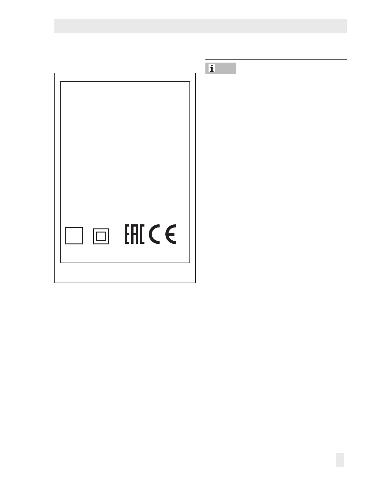
3.1.1 Front panel
F1
F2
F1
Display
F2
USB port
(USB ash drive not included in the scope of delivery)
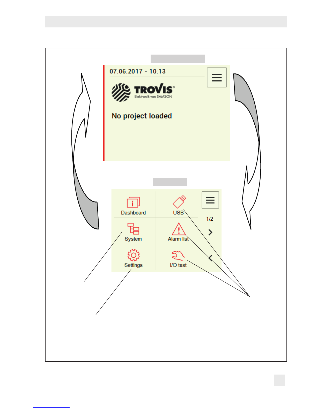
Fig.2: Operating controls located on the front panel of the device
Touch screen (
F1
)
The touch screen is the main operating element.
Tap the menu button on the top right-hand corner of the screen to open various levels. Depending on the level, various functions can be executed by tapping the dis-
played buttons (see Fig.3).
USB port (
F2
)
The USB port is accessible after opening the lid. Data can be transferred from a USB ash
drive inserted into the port to the unit and vice versa.
− USB ash drive requirements: 2.0 with FAT32
Page 11
EB 6611-2 EN 11
Design and principle of operation
Dashboard
Main menu
Main menu or
login
Buttons for frequent
actions
Menu structure de-
pending on project
System settings
Appearance varies depending on the program and the user privileges.
Fig.4: Structure of the TROVIS6611-2 Control and Automation Unit
Page 12
12 EB 6611-2 EN
Design and principle of operation
3.1.2 Back of device
R1
R8
R7
R6
R5
R4
R3
R2
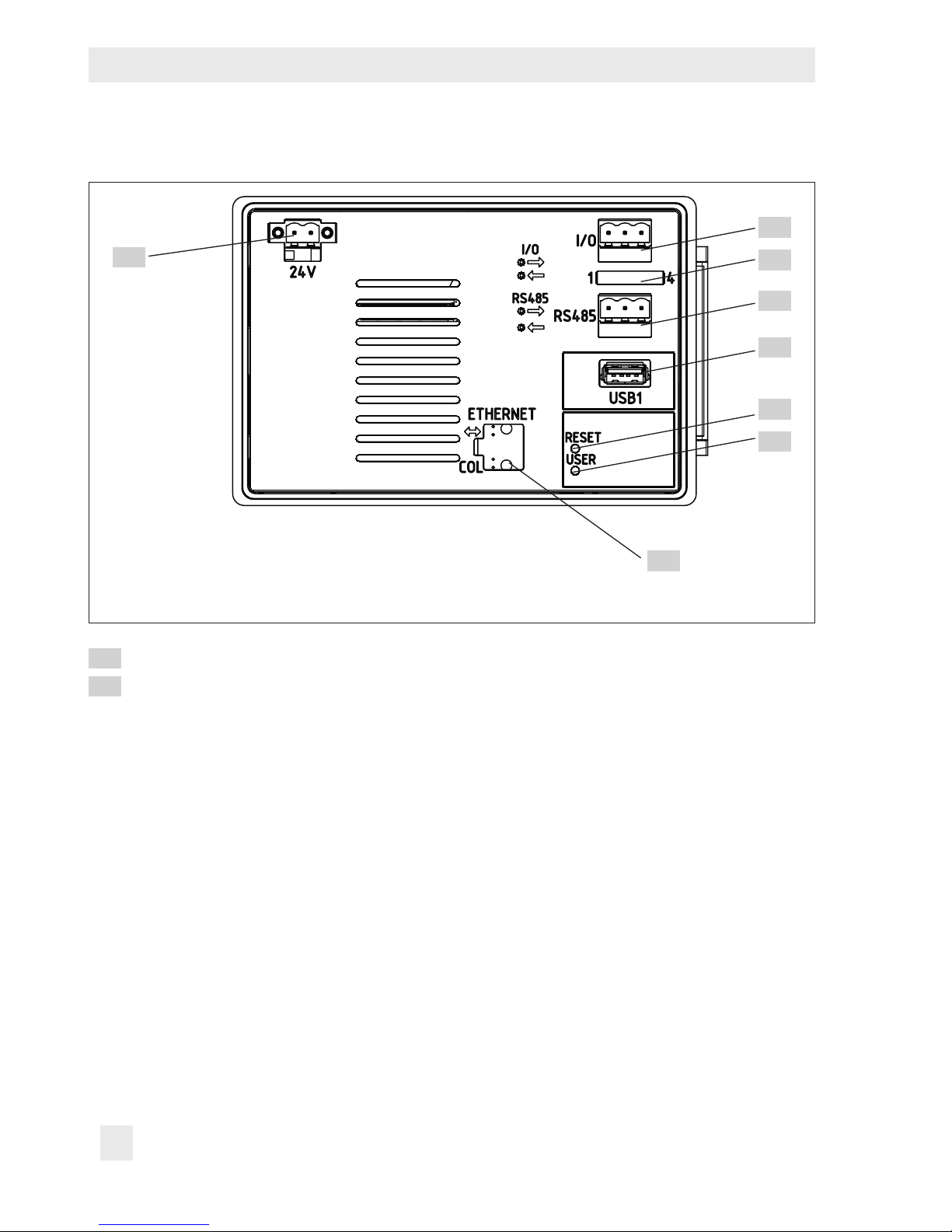
Fig.3: Operating controls located on the back of the device
Power supply (see section5.2)
Connection for I/O bus (physical inputs on the input/output modules)
Distributed I/O modules are required to connect the physical input and outputs. The
two terminals are labeled "lA" and "lB" and must be wired consistently in exactly the
same way.
Maximum cable core length: 1200m
A maximum of six I/O modules (e.g. TROVIS6620, 6625, 6630 or 6640) can be
connected to one TROVIS6611-2 Control and Automation Unit.
R1
R2
Page 13
EB 6611-2 EN 13
Design and principle of operation
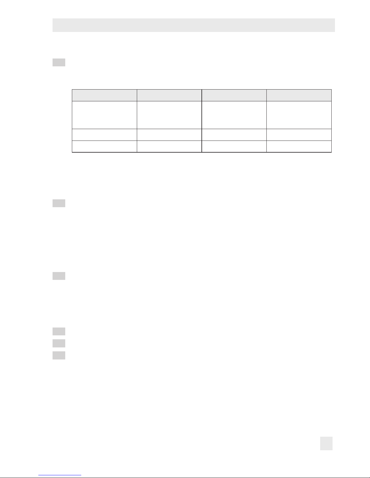
Jumper for RS-485 conguration
The jumpers are not set in the delivered state. Refer to the following table for the required setting.
1 2 3 4
Bus termination fur
I/O bus
Bus bias voltage for
Modbus (jumper3
must be closed)
Bus bias voltage for
Modbus (jumper2
must be closed)
Bus termination fur
Modbus
Closed = Active Closed = Active Closed = Active Closed = Active
Open = Not active Open = Not active Open = Not active Open = Not active
Close jumper1 if TROVIS6611-2 is at the end of the I/O bus line.
Close jumpers 2 and 3 to activate the Modbus bias voltage (if TROVIS6611-2 is used as a
Modbus RTU master).
Close jumper4 if TROVIS6611-2 is at the end of the bus.
Connection for Modbus (RS-485 2W)
The TROVIS6611-2 Control and Automation Unit supports the Modbus-RTU eldbus
protocol with two-wire system. The corresponding jumpers must be set for the terminating resistors or bias voltage. Bus properties, such as master or slave operation, data
bits, parity and stop bits must be congured in the SAMSON Graphical Project Management Tool software. The two terminals are labeled "RA" and "RB" and must be
wired consistently in exactly the same way.
USB port
Functions:
− Load and save data
− Memory extension for historical data
USB ash drive requirements: 2.0 with FAT32
Reset key for restart
User key
Ethernet connection
Data transmission rate: 100Mbit/s
Host name: Fallback IP-Adresse 172.30.66.11
The Ethernet connection can be congured and activated on site at the device. The services (SSH, FTPES, HTTPS, AVAHI (see section5.3.4) are deactivated in the delivered
state. However, the TROVIS6611-2 Control and Automation Unit in the default state
obtains the IP addresses over DHCP.
R3
R4
R5
R6
R7
R8
Page 14
14 EB 6611-2 EN
Design and principle of operation
3.2 Accessories
Accessories
− Terminal and installation set (included in the scope of delivery) ........ Item no. 1402-1561
− TROVIS6620-1 I/O Module ........................................................ Conf. ID: 4829008
− TROVIS6625 Input Module
1)
....................................................... Conf. ID: 2649861
− TROVIS 6630 AO Module ............................................................Conf. ID: 3714719
− TROVIS 6640 AI Module ..............................................................Conf. ID: 3714720
− Room panel depending on application .......................................... On request
− TROVIS6690 Graphical Project Management Tool (demo version) .. Conf. ID: 3004922
− TROVIS6690 Graphical Project Management Tool (1 AS version) ... Conf. ID: 3004921
− TROVIS6690 Graphical Project Management Tool (3 AS version) ... Conf. ID: 3004920
− TROVIS6690 Graphical Project Management Tool (full version) ...... Conf. ID: 2039168
1)
Only with 24VAC power supply (not DC)
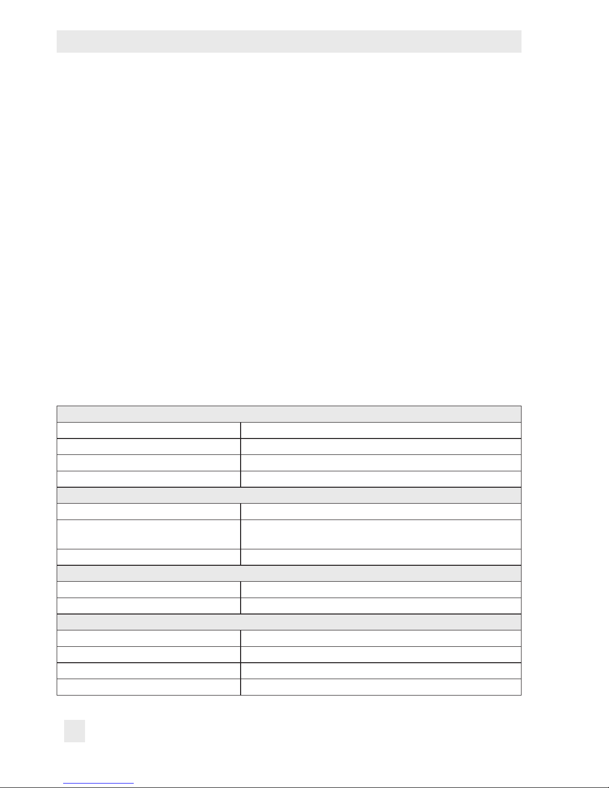
3.3 Technical data
Auxiliary power
Power supply 24VAC/DC
Power consumption 8VA/W
Connection 2-pin screw clamp terminal (orange)
Wire cross-section Up to 1.5mm²
Permissible ambient conditions
Operating temperature 0 to 55°C
Transportation and storage
temperature
–20 to +70°C
Relative humidity 5 to 95%, no dew formation
Electromagnetic compatibility
Noise emission According to EN 61000-6-3
Noise immunity According to EN 61000-6-2
Device safety
Degree of protection II according to DINEN61140
Overvoltage category II according to DINEN60664-1
Degree of contamination 2 according to DINEN60664-1
Degree of protection With seal for panel mounting: IP41 according to IEC60529
Page 15

EB 6611-2 EN 15
Design and principle of operation
Display
Key gures 3.5“ QVGA, resistive touch screen
Resolution 320 x 240 pixel
Installation
Dimensions W x H x D including terminals: 147 x 96 x 50mm
Mounting Panel mounting
Panel cutout W x H: 138 x 92mm (recommended installation depth: min.
80mm)
Weight Approx. 0.4kg
Interfaces
Serial interfaces 1x RS-485 Modbus-RTU (3-pin screw clamp terminal)
1x RS-485 I/O bus (3-pin screw clamp terminal) for
TROVIS6620
Ethernet 1x RJ-45 10/100Mbit, BACnet IP (AMEV Prole AS-A,
AS-B)
USB 2x USB 2.0A, (FAT32)
Compliance
·
3.4 Dimensions in mm
Required mounting
depth: min. 80mm
147
9650
10
Page 16

16 EB 6611-2 EN
Mounting and start-up
4 Measures for preparation
After receiving the shipment, proceed as follows:
1. Check the scope of delivery. Compare
the shipment received against the delivery note.
2. Check the shipment for transportation
damage. Report any damage to
SAMSON and the forwarding agent
(refer to delivery note).
4.1 Unpacking
Do not remove the packaging until immediately before mounting and start-up.
1. Remove the packaging from the control
and automation unit.
2. Dispose of the packaging in accordance
with the valid regulations.
4.2 Transporting
− Protect the unit against external inuenc-
es (e.g. impact).
− Protect the unit against moisture and dirt.
− Observe the permissible transportation
temperature of –20 to +70°C.
4.3 Storage
Risk of damage to the unit due to improper
storage.
− Observe storage instructions.
− Avoid long storage times.
− Contact SAMSON in case of different stor-
age conditions or long storage periods.
We recommend regularly checking the unit
and the prevailing storage conditions during
long storage times.
Storage instructions
− Protect the unit against moisture, dirt and
other external inuences (e.g. impact).
− Make sure that the ambient air is free of
acids or other corrosive media.
− Observe the permissible storage tem-
perature from –20 to +70°C.
− Do not place any objects on the unit.
5 Mounting and start-up
5.1 Installation
The control and automation unit is mainly
designed for panel mounting.
Panel cut-out (W x H): 138 x 92mm
Required mounting depth: min. 80mm
Î Make the panel cut-out.
Note
NOTICE
!
Note
Page 17

EB 6611-2 EN 17
Mounting and start-up
Î Push the unit from the front through the
panel cut-out.
Î Slide the supplied screw rails into the
guide rails: the clamps on the screw rails
must face towards the control panel.
Î Fasten the screw rails with the supplied
screws: the tips of the screws must point
towards the control panel.
Î Connect the wiring as described in sec-
tion5.2.
5.2 Electrical connection
Malfunction due to incorrect electrical connection.
− Upon installation of the electric cables, you
are required to observe the VDE regulations as well as the regulations of your local power supplier.
− Do not ground the power supply (trans-
former or switch-mode power supply).
− The wiring must be performed by properly
trained and experienced personnel only.
Surge protection
Î If signal lines are installed outside build-
ings or over large distances, make sure
appropriate surge or overvoltage protection measures are taken. Such measures
are indispensable for bus lines.
Î The shield of signal lines installed outside
buildings must have current conducting
capacity and must be grounded on both
sides.
Î Install surge diverters at the control cabi-
net inlet.
Electrical connection
The terminals have reverse polarity protection:
Î Connect the unit to the power
supply (24V).
5.3 Start-up
5.3.1 User login
Î Select "Login" in the menu ( button).
Î Enter your user name and password
("admin").
Insufcient security due to generally accessible password.
Change the administrator password
("admin") after rst login.
5.3.2 Loading a project
Î Insert the USB ash drive containing the
project into the front USB port.
Î Go to the main menu ( button).
Î Select "Load project" in "USB" and select
the required project.
Select "USB" to perform further actions:
− Save project
− Update the rmware
NOTICE
!
NOTICE
!
NOTICE
!
Page 18

18 EB 6611-2 EN
Mounting and start-up
5.3.3 Setting the system time
Î Go to the main menu ( button).
Î Select "Date and time" in "Settings".
Î Change the time and date.
Î Select "Apply" in the menu (
button) to
save changes.
5.3.4 Network settings
The unit has an integrated web server
(TROVIS MOBILE), which can be simply accessed over the network and browser
through the IP address. It must have the same
address as the end device (smartphone,
notebook, tablet computer, computer, etc.)
and an active HTTPS.
TROVIS MOBILE is designed for modern web
browsers, e.g. Mozilla Firefox in version
V.45 and higher. Access to the Internet requires port forwarding using a router (e.g.
VPN) to be set up on site.
The LAN setting is set to DHCP in the default
setting. In this setting, it is assumed that the
TROVIS6611-2 Control and Automation
Unit is assigned to an IP address, e.g.
belonging to a router. However, the IP
address is not assigned, for example, when
the TROVIS6611-2 unit is directly connected
to a laptop using a network cable. In this
case, DHCP must be deactivated to allow the
preset static IP address to be used. The
currently used and active IP address can be
found in [Main menu > Device information >
Network: eth0]. This information is available
regardless of the user role.
Î Go to the main menu ( button).
Î Select "Network settings" in "Settings".
Î Set the "LAN port" to ON.
Î Select "Back one level" in the menu (
button) to exit the level.
Î Set all other parameters in "LAN set-
tings":
− DHCP: ON (= default)
− IP address: 172.30.66.11 (= default)
− Subnet mask:
255.255.0.0
(= default)
− Host name: TROVIS-6111-2-xxx (xxx
= device-specic MAC address)
− DNS server
− NTP server
Î If necessary, select "Services" in "Net-
work":
− Activate FTPS for use with graphical
project management (default = OFF)
− Activate HTTPS for the use of the inte-
grated TROVIS-MOBILE web server
(default = OFF)
− SSH for console access using the
"root" user role
Impaired device function and loss of warranty through the improper use of the "root"
user role.
− Only activate SSH for troubleshooting and
administration activities performed by
trained personnel.
− Do not leave the SSH constantly activated.
− Assign a "root" password to protect its ac-
cess.
Note
NOTICE
!
Page 19

EB 6611-2 EN 19
Mounting and start-up
Î Select "Apply" in the menu ( button) to
save changes.
5.3.5 Assigning modules
Î Go to the main menu ( button).
Î Select "Module assignment" in "Set-
tings".
The logical modules are listed.
Î Select one physical module for each logi-
cal module one after the other.
Î The LEDs of a physical module blink after
it has been selected. Conrm selection by
checking the box (top right) or repeat selection procedure until the correct physical module has been selected.
Î Select "Apply" in the menu (
button) to
save changes.
We recommend performing the restore
function (“Restoring the system” in “Settings”)
after assigning the module. This ensures that
the settings remain saved even after a power
failure.
5.3.6 Calibrating the touch
screen
Î Go to the main menu ( button).
Î Select "Touch screen calibration" in "Set-
tings". Select "Start touch screen calibration".
Î Tap the crosshair with a pointed item
each time it appears on the screen.
5.4 Quick check
"I/O test" allows the unit's ability to function
to be checked. It allows you to check all the
connected modules and the physical inputs
and outputs.
Î After changing to the main menu (
but-
ton), select "I/O test".
Î Manually switch the outputs one after the
other to check that they function.
Note
Page 20

20 EB 6611-2 EN
Mounting and start-up
User
Load project
Set system time
Set network
Assign modules
Calibrate touch screen
Operate system on site
Reset unit
Create new user
Update the rmware
Default user NO NO NO NO NO YES NO NO NO
User NO YES NO NO NO YES NO NO NO
Service YES YES YES YES YES YES YES NO NO
Administrator YES YES YES YES YES YES YES YES YES
Fig.5: User roles
Fig.6: TROVIS MOBILE
Page 21

EB 6611-2 EN 21
Operation
6 Operation
6.1 User administration
User administration is performed over the
TROVIS MOBILE web server (see sec-
tion5.3.4 and Fig.6).
Four different user roles can be assigned to
users (see Fig.5).
6.2 Operating the system
The system is operated in "System". It depends on the loaded project.
Î After changing to the main menu ( but-
ton), select "System".
6.3 Reset unit
Resetting to rst start-up
By resetting to rst start-up, all system parameters are set to the state upon delivery of
the project.
Î Press the reset key on the back of the de-
vice.
Restoring the system
The "Restore system" command in "Settings"
allows the system to be restored to a certain
point. Once set, settings can be reset to this
point again at any time.
Î Go to the main menu (
button).
Î Select "Restore system" in "Settings".
Resetting to default settings
Resetting to default settings causes all settings made during start-up (project, system
time, network, module assignment) to be deleted.
Î Save data to a USB ash drive before re-
setting to default settings.
Î Press reset and user keys on the back of
the device simultaneously. Hold the user
key pressed until the reading indicates a
reset to default settings.
6.4 Setting up a WiFi hotspot
External hardware (e.g. computer, laptop,
smartphone, tablet computer) can be used to
establish a WiFi connection to the
TROVIS6611-2 Control and Automation
Unit. The unit's released services (e.g. web
server, connection to the graphical project
management tool) can be accessed over a
WiFi hotspot. It can only be established
using a WiFi stick
1)
, within wireless
coverage and when the end devices have
been connected properly to the WiFi
provided by the stick.
1)
WiFi sticks must support the approved chips
with appropriate drives, e.g. Edimax EW7811Un.
Page 22

22 EB 6611-2 EN
Decommissioning and disassembly
7 Servicing
The control and automation unit was
checked by SAMSON before it left the factory.
− The product warranty becomes void if
service or repair work not described in
these instructions is performed without
prior agreement by SAMSON's After-sales
Service department.
− Only use original spare parts by
SAMSON, which comply with the original
specications.
7.1 Updating the rmware
The unit's rmware needs to be updated after certain applications and functions have
been revised. The rmware is updated using
a USB ash drive
1)
containing the latest rm-
ware.
1)
The USB ash drive must have the FAT32 format, assigned the name "TROVIS6611" and
have the same folder structure.
This procedure requires administrator privileges.
Î Insert the USB ash drive containing the
rmware into the front USB port.
Î Go to the main menu ( button).
Î Select "Update rmware" in "USB" and
select the required project.
7.2 Preparation for return shipment
Defective units can be returned to SAMSON
for repair.
Proceed as follows to return devices to
SAMSON:
1. Put the unit out of operation.
2. Send the unit to your nearest SAMSON
subsidiary. SAMSON subsidiaries are
listed on our website at
uwww.samson.de > Contact.
8 Malfunctions
Î Troubleshooting (see Table1)
Contact SAMSON's After-sales Service department for malfunctions not listed in the ta-
ble.
9 Decommissioning and disas-
sembly
9.1 Decommissioning
1. Disconnect the unit from the power sup-
ply.
2. Undo the screws on the guide rails and
remove the unit.
Note
Note
Page 23

EB 6611-2 EN 23
Annex
9.2 Disposal
Î Observe local, national and internation-
al refuse regulations.
Î Do not dispose of components, lubri-
cants, and hazardous substances together with your other household waste.
10 Annex
10.1 After-sales service
Contact SAMSON's After-sales Service department for support concerning service or
repair work or when malfunctions or defects
arise.
E-mail
You can reach the After-sales Service Department at aftersalesservice@samson.de.
Addresses of SAMSONAG and its subsidiaries
The addresses of SAMSON AG, its subsidiaries, representatives and service facilities
worldwide can be found on the SAMSON
website (www.samson.de) or in all SAMSON
product catalogs.
Required specications
Please submit the following details:
− Order number and position number in
the order
− Type, serial number, rmware version,
device version
Table1: Troubleshooting
Error Possible reasons Recommended action
Screen remains black. No or incorrect power supply
connected.
Check the power supply and con-
nections (see section5.2).
Readings on screen not
legible.
No or incorrectly set reading
area of the screen.
Recalibrate screen (see sec-
tion5.3.6).
System components do not
perform the required actions.
Wrong project loaded or project
deleted.
Reload project (see section5.3.2).
Modules incorrectly/not
assigned.
Perform quick check (see sec-
tion5.4) and reassign modules, if
necessary (see section5.3.5).
TROVIS MOBILE web server
cannot be used.
Network settings are incorrect. Check settings and change, if
necessary (see section5.3.4).
Page 24

10.2 Licenses
10.2.1 GNU GENERAL PUBLIC LICENSE, Version 2, June 1991
Copyright (C) 1989, 1991 Free Software Foundation, Inc.
51 Franklin Street, Fifth Floor, Boston, MA 02110-1301, USA
Everyone is permitted to copy and distribute verbatim copies of this license document, but changing it is
not allowed.
Preamble
The licenses for most software are designed to take away your freedom to share and change it. By contrast, the GNU General Public License is intended to guarantee your freedom to share and change free
software--to make sure the software is free for all its users. This General Public License applies to most of
the Free Software Foundation‘s software and to any other program whose authors commit to using it.
(Some other Free Software Foundation software is covered by the GNU Lesser General Public License instead.) You can apply it to your programs, too.
When we speak of free software, we are referring to freedom, not price. Our General Public
Licenses are designed to make sure that you have the freedom to distribute copies of free
software (and charge for this service if you wish), that you receive source code or can get it if
you want it, that you can change the software or use pieces of it in new free programs; and
that you know you can do these things.
To protect your rights, we need to make restrictions that forbid anyone to deny you these
rights or to ask you to surrender the rights. These restrictions translate to certain responsibilities for you if you distribute copies of the software, or if you modify it.
For example, if you distribute copies of such a program, whether gratis or for a fee, you must
give the recipients all the rights that you have. You must make sure that they, too, receive or
can get the source code. And you must show them these terms so they know their rights.
We protect your rights with two steps: (1) copyright the software, and (2) offer you this license which gives you legal permission to copy, distribute and/or modify the software.
Also, for each author‘s protection and ours, we want to make certain that everyone under-
stands that there is no warranty for this free software. If the software is modied by someone
else and passed on, we want its recipients to know that what they have is not the original, so
that any problems introduced by others will not reect on the original authors‘ reputations.
Finally, any free program is threatened constantly by software patents. We wish to avoid the
danger that redistributors of a free program will individually obtain patent licenses, in effect
24 EB 6611-2 EN
Annex
Page 25

making the program proprietary. To prevent this, we have made it clear that any patent must
be licensed for everyone‘s free use or not licensed at all.
The precise terms and conditions for copying, distribution and modication follow.
TERMS AND CONDITIONS FOR COPYING, DISTRIBUTION AND MODIFICATION
0. This License applies to any program or other work which contains a notice placed by the copyright
holder saying it may be distributed under the terms of this General Public License. The „Program“,
below, refers to any such program or work, and a „work based on the Program“ means either the
Program or any derivative work under copyright law: that is to say, a work containing the Program
or a portion of it, either verbatim or with modications and/or translated into another language.
(Hereinafter, translation is included without limitation in the term „modication“.) Each licensee is
addressed as „you“.
Activities other than copying, distribution and modication are not covered by this License; they are
outside its scope. The act of running the Program is not restricted, and the output from the Program is
covered only if its contents constitute a work based on the Program (independent of having been
made by running the Program). Whether that is true depends on what the Program does.
1. You may copy and distribute verbatim copies of the Program‘s source code as you receive it, in any
medium, provided that you conspicuously and appropriately publish on each copy an appropriate
copyright notice and disclaimer of warranty; keep intact all the notices that refer to this License and
to the absence of any warranty; and give any other recipients of the Program a copy of this License
along with the Program.
You may charge a fee for the physical act of transferring a copy, and you may at your option offer
warranty protection in exchange for a fee.
2. You may modify your copy or copies of the Program or any portion of it, thus forming a work based
on the Program, and copy and distribute such modications or work under the terms of Section 1
above, provided that you also meet all of these conditions:
a) You must cause the modied les to carry prominent notices stating that you changed the les
and the date of any change.
b) You must cause any work that you distribute or publish, that in whole or in part contains or is
derived from the Program or any part thereof, to be licensed as a whole at no charge to all third
parties under the terms of this License.
c) If the modied program normally reads commands interactively when run, you must cause it,
when started running for such interactive use in the most ordinary way, to print or display an
announcement including an appropriate copyright notice and a notice that there is no warranty
(or else, saying that you provide a warranty) and that users may redistribute the program under
these conditions, and telling the user how to view a copy of this License. (Exception: if the Pro-
EB 6611-2 EN 25
Annex
Page 26

gram itself is interactive but does not normally print such an announcement, your work based on
the Program is not required to print an announcement.)
These requirements apply to the modied work as a whole. If identiable sections of that work are
not derived from the Program, and can be reasonably considered independent and separate works
in themselves, then this License, and its terms, do not apply to those sections when you distribute
them as separate works. But when you distribute the same sections as part of a whole which is a
work based on the Program, the distribution of the whole must be on the terms of this License, whose
permissions for other licensees extend to the entire whole, and thus to each and every part regardless of who wrote it.
Thus, it is not the intent of this section to claim rights or contest your rights to work written entirely by
you; rather, the intent is to exercise the right to control the distribution of derivative or collective
works based on the Program.
In addition, mere aggregation of another work not based on the Program with the Program (or with
a work based on the Program) on a volume of a storage or distribution medium does not bring the
other work under the scope of this License.
3. You may copy and distribute the Program (or a work based on it, under Section 2) in object code or
executable form under the terms of Sections 1 and 2 above provided that you also do one of the following:
a) Accompany it with the complete corresponding machine-readable source code, which must be
distributed under the terms of Sections 1 and 2 above on a medium customarily used for soft-
ware interchange; or.
b) Accompany it with a written offer, valid for at least three years, to give any third party, for a
charge no more than your cost of physically performing source distribution, a complete machine-readable copy of the corresponding source code, to be distributed under the terms of Sec-
tions 1 and 2 above on a medium customarily used for software interchange; or.
c) Accompany it with the information you received as to the offer to distribute corresponding
source code. (This alternative is allowed only for noncommercial distribution and only if you received the program in object code or executable form with such an offer, in accord with Subsection b above.)
The source code for a work means the preferred form of the work for making modications to it. For
an executable work, complete source code means all the source code for all modules it contains, plus
any associated interface denition les, plus the scripts used to control compilation and installation
of the executable. However, as a special exception, the source code distributed need not include
anything that is normally distributed (in either source or binary form) with the major components
(compiler, kernel, and so on) of the operating system on which the executable runs, unless that component itself accompanies the executable.
26 EB 6611-2 EN
Annex
Page 27

If distribution of executable or object code is made by offering access to copy from a designated
place, then offering equivalent access to copy the source code from the same place counts as distribution of the source code, even though third parties are not compelled to copy the source along with
the object code.
4. You may not copy, modify, sublicense, or distribute the Program except as expressly provided under
this License. Any attempt otherwise to copy, modify, sublicense or distribute the Program is void, and
will automatically terminate your rights under this License. However, parties who have received copies, or rights, from you under this License will not have their licenses terminated so long as such parties remain in full compliance.
5. You are not required to accept this License, since you have not signed it. However, nothing else
grants you permission to modify or distribute the Program or its derivative works. These actions are
prohibited by law if you do not accept this License. Therefore, by modifying or distributing the Program (or any work based on the Program), you indicate your acceptance of this License to do so,
and all its terms and conditions for copying, distributing or modifying the Program or works based
on it.
6. Each time you redistribute the Program (or any work based on the Program), the recipient automatically receives a license from the original licensor to copy, distribute or modify the Program subject to
these terms and conditions. You may not impose any further restrictions on the recipients‘ exercise of
the rights granted herein. You are not responsible for enforcing compliance by third parties to this License.
7. If, as a consequence of a court judgment or allegation of patent infringement or for any other reason (not limited to patent issues), conditions are imposed on you (whether by court order, agreement
or otherwise) that contradict the conditions of this License, they do not excuse you from the conditions of this License. If you cannot distribute so as to satisfy simultaneously your obligations under
this License and any other pertinent obligations, then as a consequence you may not distribute the
Program at all. For example, if a patent license would not permit royalty-free redistribution of the
Program by all those who receive copies directly or indirectly through you, then the only way you
could satisfy both it and this License would be to refrain entirely from distribution of the Program.
If any portion of this section is held invalid or unenforceable under any particular circumstance, the
balance of the section is intended to apply and the section as a whole is intended to apply in other
circumstances.
It is not the purpose of this section to induce you to infringe any patents or other property right
claims or to contest validity of any such claims; this section has the sole purpose of protecting the integrity of the free software distribution system, which is implemented by public license practices. Many people have made generous contributions to the wide range of software distributed through that
system in reliance on consistent application of that system; it is up to the author/donor to decide if
EB 6611-2 EN 27
Annex
Page 28

he or she is willing to distribute software through any other system and a licensee cannot impose
that choice.
This section is intended to make thoroughly clear what is believed to be a consequence of the rest of
this License.
8. If the distribution and/or use of the Program is restricted in certain countries either by patents or by
copyrighted interfaces, the original copyright holder who places the Program under this License may
add an explicit geographical distribution limitation excluding those countries, so that distribution is
permitted only in or among countries not thus excluded. In such case, this License incorporates the
limitation as if written in the body of this License.
9. The Free Software Foundation may publish revised and/or new versions of the General Public License from time to time. Such new versions will be similar in spirit to the present version, but may
differ in detail to address new problems or concerns.
Each version is given a distinguishing version number. If the Program species a version
number of this License which applies to it and „any later version“, you have the option of
following the terms and conditions either of that version or of any later version published
by the Free Software Foundation. If the Program does not specify a version number of this
License, you may choose any version ever published by the Free Software Foundation.
10. If you wish to incorporate parts of the Program into other free programs whose distribution conditions are different, write to the author to ask for permission. For software which is copyrighted by the
Free Software Foundation, write to the Free Software Foundation; we sometimes make exceptions for
this. Our decision will be guided by the two goals of preserving the free status of all derivatives of
our free software and of promoting the sharing and reuse of software generally.
NO WARRANTY
11. BECAUSE THE PROGRAM IS LICENSED FREE OF CHARGE, THERE IS NO WARRANTY FOR THE
PROGRAM, TO THE EXTENT PERMITTED BY APPLICABLE LAW. EXCEPT WHEN OTHERWISE STATED IN WRITING THE COPYRIGHT HOLDERS AND/OR OTHER PARTIES PROVIDE THE PROGRAM
„AS IS“ WITHOUT WARRANTY OF ANY KIND, EITHER EXPRESSED OR IMPLIED, INCLUDING, BUT
NOT LIMITED TO, THE IMPLIED WARRANTIES OF MERCHANTABILITY AND FITNESS FOR A PARTICULAR PURPOSE. THE ENTIRE RISK AS TO THE QUALITY AND PERFORMANCE OF THE PROGRAM IS WITH YOU. SHOULD THE PROGRAM PROVE DEFECTIVE, YOU ASSUME THE COST OF
ALL NECESSARY SERVICING, REPAIR OR CORRECTION.
12. IN NO EVENT UNLESS REQUIRED BY APPLICABLE LAW OR AGREED TO IN WRITING WILL ANY
COPYRIGHT HOLDER, OR ANY OTHER PARTY WHO MAY MODIFY AND/OR REDISTRIBUTE THE
PROGRAM AS PERMITTED ABOVE, BE LIABLE TO YOU FOR DAMAGES, INCLUDING ANY GENERAL, SPECIAL, INCIDENTAL OR CONSEQUENTIAL DAMAGES ARISING OUT OF THE USE OR
INABILITY TO USE THE PROGRAM (INCLUDING BUT NOT LIMITED TO LOSS OF DATA OR DATA
28 EB 6611-2 EN
Annex
Page 29

BEING RENDERED INACCURATE OR LOSSES SUSTAINED BY YOU OR THIRD PARTIES OR A FAILURE OF THE PROGRAM TO OPERATE WITH ANY OTHER PROGRAMS), EVEN IF SUCH HOLDER
OR OTHER PARTY HAS BEEN ADVISED OF THE POSSIBILITY OF SUCH DAMAGES.
END OF TERMS AND CONDITIONS
10.2.2 GNU GENERAL PUBLIC LICENSE, Version 3, 29 June 2007
Copyright © 2007 Free Software Foundation, Inc. <http://fsf.org/>
Everyone is permitted to copy and distribute verbatim copies of this license document, but changing it is
not allowed.
Preamble
The GNU General Public License is a free, copyleft license for software and other kinds of works.
The licenses for most software and other practical works are designed to take away your freedom to
share and change the works. By contrast, the GNU General Public License is intended to guarantee your
freedom to share and change all versions of a program--to make sure it remains free software for all its
users. We, the Free Software Foundation, use the GNU General Public License for most of our software;
it applies also to any other work released this way by its authors. You can apply it to your programs,
too.
When we speak of free software, we are referring to freedom, not price. Our General Public Licenses
are designed to make sure that you have the freedom to distribute copies of free software (and charge
for them if you wish), that you receive source code or can get it if you want it, that you can change the
software or use pieces of it in new free programs, and that you know you can do these things.
To protect your rights, we need to prevent others from denying you these rights or asking you to surrender the rights. Therefore, you have certain responsibilities if you distribute copies of the software, or if
you modify it: responsibilities to respect the freedom of others.
For example, if you distribute copies of such a program, whether gratis or for a fee, you must pass on to
the recipients the same freedoms that you received. You must make sure that they, too, receive or can get
the source code. And you must show them these terms so they know their rights.
Developers that use the GNU GPL protect your rights with two steps: (1) assert copyright on the software,
and (2) offer you this License giving you legal permission to copy, distribute and/or modify it.
For the developers‘ and authors‘ protection, the GPL clearly explains that there is no warranty for this
free software. For both users‘ and authors‘ sake, the GPL requires that modied versions be marked as
changed, so that their problems will not be attributed erroneously to authors of previous versions.
Some devices are designed to deny users access to install or run modied versions of the software inside
them, although the manufacturer can do so. This is fundamentally incompatible with the aim of protect-
EB 6611-2 EN 29
Annex
Page 30

ing users‘ freedom to change the software. The systematic pattern of such abuse occurs in the area of
products for individuals to use, which is precisely where it is most unacceptable. Therefore, we have designed this version of the GPL to prohibit the practice for those products. If such problems arise substantially in other domains, we stand ready to extend this provision to those domains in future versions of the
GPL, as needed to protect the freedom of users.
Finally, every program is threatened constantly by software patents. States should not allow patents to
restrict development and use of software on general-purpose computers, but in those that do, we wish to
avoid the special danger that patents applied to a free program could make it effectively proprietary. To
prevent this, the GPL assures that patents cannot be used to render the program non-free.
The precise terms and conditions for copying, distribution and modication follow.
TERMS AND CONDITIONS
0. Denitions.
“This License” refers to version 3 of the GNU General Public License.
“Copyright” also means copyright-like laws that apply to other kinds of works, such as semiconduc-
tor masks.
“The Program” refers to any copyrightable work licensed under this License. Each licensee is ad-
dressed as “you”. “Licensees” and “recipients” may be individuals or organizations.
To “modify” a work means to copy from or adapt all or part of the work in a fashion requiring copy-
right permission, other than the making of an exact copy. The resulting work is called a “modied
version” of the earlier work or a work “based on” the earlier work.
A “covered work” means either the unmodied Program or a work based on the Program.
To “propagate” a work means to do anything with it that, without permission, would make you directly or secondarily liable for infringement under applicable copyright law, except executing it on a
computer or modifying a private copy. Propagation includes copying, distribution (with or without
modication), making available to the public, and in some countries other activities as well.
To “convey” a work means any kind of propagation that enables other parties to make or receive
copies. Mere interaction with a user through a computer network, with no transfer of a copy, is not
conveying.
An interactive user interface displays “Appropriate Legal Notices” to the extent that it includes a convenient and prominently visible feature that (1) displays an appropriate copyright notice, and (2)
tells the user that there is no warranty for the work (except to the extent that warranties are provided), that licensees may convey the work under this License, and how to view a copy of this License. If
the interface presents a list of user commands or options, such as a menu, a prominent item in the
list meets this criterion.
30 EB 6611-2 EN
Annex
Page 31

1. Source Code.
The “source code” for a work means the preferred form of the work for making modications to it.
“Object code” means any non-source form of a work.
A “Standard Interface” means an interface that either is an ofcial standard dened by a recognized standards body, or, in the case of interfaces specied for a particular programming language,
one that is widely used among developers working in that language.
The “System Libraries” of an executable work include anything, other than the work as a whole, that
(a) is included in the normal form of packaging a Major Component, but which is not part of that
Major Component, and (b) serves only to enable use of the work with that Major Component, or to
implement a Standard Interface for which an implementation is available to the public in source
code form. A “Major Component”, in this context, means a major essential component (kernel, win-
dow system, and so on) of the specic operating system (if any) on which the executable work runs,
or a compiler used to produce the work, or an object code interpreter used to run it.
The “Corresponding Source” for a work in object code form means all the source code needed to
generate, install, and (for an executable work) run the object code and to modify the work, including scripts to control those activities. However, it does not include the work‘s System Libraries, or
general-purpose tools or generally available free programs which are used unmodied in performing those activities but which are not part of the work. For example, Corresponding Source includes
interface denition les associated with source les for the work, and the source code for shared libraries and dynamically linked subprograms that the work is specically designed to require, such
as by intimate data communication or control ow between those subprograms and other parts of
the work.
The Corresponding Source need not include anything that users can regenerate automatically from
other parts of the Corresponding Source.
The Corresponding Source for a work in source code form is that same work.
2. Basic Permissions.
All rights granted under this License are granted for the term of copyright on the Program, and are
irrevocable provided the stated conditions are met. This License explicitly afrms your unlimited permission to run the unmodied Program. The output from running a covered work is covered by this
License only if the output, given its content, constitutes a covered work. This License acknowledges
your rights of fair use or other equivalent, as provided by copyright law.
You may make, run and propagate covered works that you do not convey, without conditions so
long as your license otherwise remains in force. You may convey covered works to others for the sole
purpose of having them make modications exclusively for you, or provide you with facilities for
running those works, provided that you comply with the terms of this License in conveying all material for which you do not control copyright. Those thus making or running the covered works for you
EB 6611-2 EN 31
Annex
Page 32

must do so exclusively on your behalf, under your direction and control, on terms that prohibit them
from making any copies of your copyrighted material outside their relationship with you.
Conveying under any other circumstances is permitted solely under the conditions stated below. Sub-
licensing is not allowed; section 10 makes it unnecessary.
3. Protecting Users‘ Legal Rights From Anti-Circumvention Law.
No covered work shall be deemed part of an effective technological measure under any applicable
law fullling obligations under article 11 of the WIPO copyright treaty adopted on 20 December
1996, or similar laws prohibiting or restricting circumvention of such measures.
When you convey a covered work, you waive any legal power to forbid circumvention of technolog-
ical measures to the extent such circumvention is effected by exercising rights under this License with
respect to the covered work, and you disclaim any intention to limit operation or modication of the
work as a means of enforcing, against the work‘s users, your or third parties‘ legal rights to forbid
circumvention of technological measures.
4. Conveying Verbatim Copies.
You may convey verbatim copies of the Program‘s source code as you receive it, in any medium,
provided that you conspicuously and appropriately publish on each copy an appropriate copyright
notice; keep intact all notices stating that this License and any non-permissive terms added in accord
with section 7 apply to the code; keep intact all notices of the absence of any warranty; and give all
recipients a copy of this License along with the Program.
You may charge any price or no price for each copy that you convey, and you may offer support or
warranty protection for a fee.
5. Conveying Modied Source Versions.
You may convey a work based on the Program, or the modications to produce it from the Program,
in the form of source code under the terms of section 4, provided that you also meet all of these conditions:
a) The work must carry prominent notices stating that you modied it, and giving a relevant date.
b) The work must carry prominent notices stating that it is released under this License and any con-
ditions added under section 7. This requirement modies the requirement in section 4 to “keep
intact all notices”.
c) You must license the entire work, as a whole, under this License to anyone who comes into pos-
session of a copy. This License will therefore apply, along with any applicable section 7 additional terms, to the whole of the work, and all its parts, regardless of how they are packaged.
This License gives no permission to license the work in any other way, but it does not invalidate
such permission if you have separately received it.
32 EB 6611-2 EN
Annex
Page 33

d) If the work has interactive user interfaces, each must display Appropriate Legal Notices; howev-
er, if the Program has interactive interfaces that do not display Appropriate Legal Notices, your
work need not make them do so.
A compilation of a covered work with other separate and independent works, which are not by their
nature extensions of the covered work, and which are not combined with it such as to form a larger
program, in or on a volume of a storage or distribution medium, is called an “aggregate” if the
compilation and its resulting copyright are not used to limit the access or legal rights of the compilation‘s users beyond what the individual works permit. Inclusion of a covered work in an aggregate
does not cause this License to apply to the other parts of the aggregate.
6. Conveying Non-Source Forms.
You may convey a covered work in object code form under the terms of sections 4 and 5, provided
that you also convey the machine-readable Corresponding Source under the terms of this License, in
one of these ways:
a) Convey the object code in, or embodied in, a physical product (including a physical distribution
medium), accompanied by the Corresponding Source xed on a durable physical medium customarily used for software interchange.
b) Convey the object code in, or embodied in, a physical product (including a physical distribution
medium), accompanied by a written offer, valid for at least three years and valid for as long as
you offer spare parts or customer support for that product model, to give anyone who possesses
the object code either (1) a copy of the Corresponding Source for all the software in the product
that is covered by this License, on a durable physical medium customarily used for software interchange, for a price no more than your reasonable cost of physically performing this conveying of source, or (2) access to copy the Corresponding Source from a network server at no
charge.
c) Convey individual copies of the object code with a copy of the written offer to provide the Cor-
responding Source. This alternative is allowed only occasionally and noncommercially, and only
if you received the object code with such an offer, in accord with subsection 6b.
d) Convey the object code by offering access from a designated place (gratis or for a charge), and
offer equivalent access to the Corresponding Source in the same way through the same place at
no further charge. You need not require recipients to copy the Corresponding Source along with
the object code. If the place to copy the object code is a network server, the Corresponding
Source may be on a different server (operated by you or a third party) that supports equivalent
copying facilities, provided you maintain clear directions next to the object code saying where
to nd the Corresponding Source. Regardless of what server hosts the Corresponding Source,
you remain obligated to ensure that it is available for as long as needed to satisfy these requirements.
EB 6611-2 EN 33
Annex
Page 34

e) Convey the object code using peer-to-peer transmission, provided you inform other peers where
the object code and Corresponding Source of the work are being offered to the general public
at no charge under subsection 6d.
A separable portion of the object code, whose source code is excluded from the Corresponding
Source as a System Library, need not be included in conveying the object code work.
A “User Product” is either (1) a “consumer product”, which means any tangible personal property
which is normally used for personal, family, or household purposes, or (2) anything designed or
sold for incorporation into a dwelling. In determining whether a product is a consumer product,
doubtful cases shall be resolved in favor of coverage. For a particular product received by a particular user, “normally used” refers to a typical or common use of that class of product, regardless of the
status of the particular user or of the way in which the particular user actually uses, or expects or is
expected to use, the product. A product is a consumer product regardless of whether the product has
substantial commercial, industrial or non-consumer uses, unless such uses represent the only signicant mode of use of the product.
“Installation Information” for a User Product means any methods, procedures, authorization keys, or
other information required to install and execute modied versions of a covered work in that User
Product from a modied version of its Corresponding Source. The information must sufce to ensure
that the continued functioning of the modied object code is in no case prevented or interfered with
solely because modication has been made.
If you convey an object code work under this section in, or with, or specically for use in, a User
Product, and the conveying occurs as part of a transaction in which the right of possession and use
of the User Product is transferred to the recipient in perpetuity or for a xed term (regardless of how
the transaction is characterized), the Corresponding Source conveyed under this section must be accompanied by the Installation Information. But this requirement does not apply if neither you nor any
third party retains the ability to install modied object code on the User Product (for example, the
work has been installed in ROM).
The requirement to provide Installation Information does not include a requirement to continue to
provide support service, warranty, or updates for a work that has been modied or installed by the
recipient, or for the User Product in which it has been modied or installed. Access to a network
may be denied when the modication itself materially and adversely affects the operation of the net-
work or violates the rules and protocols for communication across the network.
Corresponding Source conveyed, and Installation Information provided, in accord with this section
must be in a format that is publicly documented (and with an implementation available to the public
in source code form), and must require no special password or key for unpacking, reading or copying.
34 EB 6611-2 EN
Annex
Page 35

7. Additional Terms.
“Additional permissions” are terms that supplement the terms of this License by making exceptions
from one or more of its conditions. Additional permissions that are applicable to the entire Program
shall be treated as though they were included in this License, to the extent that they are valid under
applicable law. If additional permissions apply only to part of the Program, that part may be used
separately under those permissions, but the entire Program remains governed by this License without
regard to the additional permissions.
When you convey a copy of a covered work, you may at your option remove any additional permissions from that copy, or from any part of it. (Additional permissions may be written to require
their own removal in certain cases when you modify the work.) You may place additional permissions on material, added by you to a covered work, for which you have or can give appropriate
copyright permission.
Notwithstanding any other provision of this License, for material you add to a covered work, you
may (if authorized by the copyright holders of that material) supplement the terms of this License
with terms:
a) Disclaiming warranty or limiting liability differently from the terms of sections 15 and 16 of this
License; or
b) Requiring preservation of specied reasonable legal notices or author attributions in that materi-
al or in the Appropriate Legal Notices displayed by works containing it; or
c) Prohibiting misrepresentation of the origin of that material, or requiring that modied versions of
such material be marked in reasonable ways as different from the original version; or
d) Limiting the use for publicity purposes of names of licensors or authors of the material; or
e) Declining to grant rights under trademark law for use of some trade names, trademarks, or ser-
vice marks; or
f) Requiring indemnication of licensors and authors of that material by anyone who conveys the
material (or modied versions of it) with contractual assumptions of liability to the recipient, for
any liability that these contractual assumptions directly impose on those licensors and authors.
All other non-permissive additional terms are considered “further restrictions” within the meaning of
section 10. If the Program as you received it, or any part of it, contains a notice stating that it is governed by this License along with a term that is a further restriction, you may remove that term. If a license document contains a further restriction but permits relicensing or conveying under this License,
you may add to a covered work material governed by the terms of that license document, provided
that the further restriction does not survive such relicensing or conveying.
EB 6611-2 EN 35
Annex
Page 36

If you add terms to a covered work in accord with this section, you must place, in the relevant source
les, a statement of the additional terms that apply to those les, or a notice indicating where to nd
the applicable terms.
Additional terms, permissive or non-permissive, may be stated in the form of a separately written li-
cense, or stated as exceptions; the above requirements apply either way.
8. Termination.
You may not propagate or modify a covered work except as expressly provided under this License.
Any attempt otherwise to propagate or modify it is void, and will automatically terminate your rights
under this License (including any patent licenses granted under the third paragraph of section 11).
However, if you cease all violation of this License, then your license from a particular copyright holder is reinstated (a) provisionally, unless and until the copyright holder explicitly and nally terminates your license, and (b) permanently, if the copyright holder fails to notify you of the violation by
some reasonable means prior to 60 days after the cessation.
Moreover, your license from a particular copyright holder is reinstated permanently if the copyright
holder noties you of the violation by some reasonable means, this is the rst time you have received
notice of violation of this License (for any work) from that copyright holder, and you cure the violation prior to 30 days after your receipt of the notice.
Termination of your rights under this section does not terminate the licenses of parties who have received copies or rights from you under this License. If your rights have been terminated and not permanently reinstated, you do not qualify to receive new licenses for the same material under section
10.
9. Acceptance Not Required for Having Copies.
You are not required to accept this License in order to receive or run a copy of the Program. Ancil-
lary propagation of a covered work occurring solely as a consequence of using peer-to-peer transmission to receive a copy likewise does not require acceptance. However, nothing other than this License grants you permission to propagate or modify any covered work. These actions infringe copyright if you do not accept this License. Therefore, by modifying or propagating a covered work, you
indicate your acceptance of this License to do so.
10. Automatic Licensing of Downstream Recipients.
Each time you convey a covered work, the recipient automatically receives a license from the origi-
nal licensors, to run, modify and propagate that work, subject to this License. You are not responsible for enforcing compliance by third parties with this License.
An “entity transaction” is a transaction transferring control of an organization, or substantially all
assets of one, or subdividing an organization, or merging organizations. If propagation of a covered work results from an entity transaction, each party to that transaction who receives a copy of
36 EB 6611-2 EN
Annex
Page 37

the work also receives whatever licenses to the work the party‘s predecessor in interest had or could
give under the previous paragraph, plus a right to possession of the Corresponding Source of the
work from the predecessor in interest, if the predecessor has it or can get it with reasonable efforts.
You may not impose any further restrictions on the exercise of the rights granted or afrmed under
this License. For example, you may not impose a license fee, royalty, or other charge for exercise of
rights granted under this License, and you may not initiate litigation (including a cross-claim or
counterclaim in a lawsuit) alleging that any patent claim is infringed by making, using, selling, offering for sale, or importing the Program or any portion of it.
11. Patents.
A “contributor” is a copyright holder who authorizes use under this License of the Program or a
work on which the Program is based. The work thus licensed is called the contributor‘s “contributor
version”.
A contributor‘s “essential patent claims” are all patent claims owned or controlled by the contributor,
whether already acquired or hereafter acquired, that would be infringed by some manner, permitted
by this License, of making, using, or selling its contributor version, but do not include claims that
would be infringed only as a consequence of further modication of the contributor version. For purposes of this denition, “control” includes the right to grant patent sublicenses in a manner consistent
with the requirements of this License.
Each contributor grants you a non-exclusive, worldwide, royalty-free patent license under the con-
tributor‘s essential patent claims, to make, use, sell, offer for sale, import and otherwise run, modify
and propagate the contents of its contributor version.
In the following three paragraphs, a “patent license” is any express agreement or commitment, however denominated, not to enforce a patent (such as an express permission to practice a patent or
covenant not to sue for patent infringement). To “grant” such a patent license to a party means to
make such an agreement or commitment not to enforce a patent against the party.
If you convey a covered work, knowingly relying on a patent license, and the Corresponding Source
of the work is not available for anyone to copy, free of charge and under the terms of this License,
through a publicly available network server or other readily accessible means, then you must either
(1) cause the Corresponding Source to be so available, or (2) arrange to deprive yourself of the
benet of the patent license for this particular work, or (3) arrange, in a manner consistent with the
requirements of this License, to extend the patent license to downstream recipients. “Knowingly relying” means you have actual knowledge that, but for the patent license, your conveying the covered
work in a country, or your recipient‘s use of the covered work in a country, would infringe one or
more identiable patents in that country that you have reason to believe are valid.
If, pursuant to or in connection with a single transaction or arrangement, you convey, or propagate
by procuring conveyance of, a covered work, and grant a patent license to some of the parties re-
EB 6611-2 EN 37
Annex
Page 38

ceiving the covered work authorizing them to use, propagate, modify or convey a specic copy of
the covered work, then the patent license you grant is automatically extended to all recipients of the
covered work and works based on it.
A patent license is “discriminatory” if it does not include within the scope of its coverage, prohibits
the exercise of, or is conditioned on the non-exercise of one or more of the rights that are specically granted under this License. You may not convey a covered work if you are a party to an arrangement with a third party that is in the business of distributing software, under which you make payment to the third party based on the extent of your activity of conveying the work, and under which
the third party grants, to any of the parties who would receive the covered work from you, a discriminatory patent license (a) in connection with copies of the covered work conveyed by you (or
copies made from those copies), or (b) primarily for and in connection with specic products or
compilations that contain the covered work, unless you entered into that arrangement, or that patent
license was granted, prior to 28 March 2007.
Nothing in this License shall be construed as excluding or limiting any implied license or other defenses to infringement that may otherwise be available to you under applicable patent law.
12. No Surrender of Others‘ Freedom.
If conditions are imposed on you (whether by court order, agreement or otherwise) that contradict
the conditions of this License, they do not excuse you from the conditions of this License. If you cannot convey a covered work so as to satisfy simultaneously your obligations under this License and
any other pertinent obligations, then as a consequence you may not convey it at all. For example, if
you agree to terms that obligate you to collect a royalty for further conveying from those to whom
you convey the Program, the only way you could satisfy both those terms and this License would be
to refrain entirely from conveying the Program.
13. Use with the GNU Affero General Public License.
Notwithstanding any other provision of this License, you have permission to link or combine any
covered work with a work licensed under version 3 of the GNU Affero General Public License into a
single combined work, and to convey the resulting work. The terms of this License will continue to
apply to the part which is the covered work, but the special requirements of the GNU Affero General
Public License, section 13, concerning interaction through a network will apply to the combination as
such.
14. Revised Versions of this License.
The Free Software Foundation may publish revised and/or new versions of the GNU General Public
License from time to time. Such new versions will be similar in spirit to the present version, but may
differ in detail to address new problems or concerns.
Each version is given a distinguishing version number. If the Program species that a certain numbered version of the GNU General Public License “or any later version” applies to it, you have the
38 EB 6611-2 EN
Annex
Page 39

option of following the terms and conditions either of that numbered version or of any later version
published by the Free Software Foundation. If the Program does not specify a version number of the
GNU General Public License, you may choose any version ever published by the Free Software
Foundation.
If the Program species that a proxy can decide which future versions of the GNU General Public License can be used, that proxy‘s public statement of acceptance of a version permanently authorizes
you to choose that version for the Program.
Later license versions may give you additional or different permissions. However, no additional obligations are imposed on any author or copyright holder as a result of your choosing to follow a later
version.
15. Disclaimer of Warranty.
THERE IS NO WARRANTY FOR THE PROGRAM, TO THE EXTENT PERMITTED BY APPLICABLE LAW.
EXCEPT WHEN OTHERWISE STATED IN WRITING THE COPYRIGHT HOLDERS AND/OR OTHER
PARTIES PROVIDE THE PROGRAM “AS IS” WITHOUT WARRANTY OF ANY KIND, EITHER EXPRESSED OR IMPLIED, INCLUDING, BUT NOT LIMITED TO, THE IMPLIED WARRANTIES OF MERCHANTABILITY AND FITNESS FOR A PARTICULAR PURPOSE. THE ENTIRE RISK AS TO THE QUALITY AND PERFORMANCE OF THE PROGRAM IS WITH YOU. SHOULD THE PROGRAM PROVE DEFECTIVE, YOU ASSUME THE COST OF ALL NECESSARY SERVICING, REPAIR OR CORRECTION.
16. Limitation of Liability.
IN NO EVENT UNLESS REQUIRED BY APPLICABLE LAW OR AGREED TO IN WRITING WILL ANY
COPYRIGHT HOLDER, OR ANY OTHER PARTY WHO MODIFIES AND/OR CONVEYS THE PROGRAM AS PERMITTED ABOVE, BE LIABLE TO YOU FOR DAMAGES, INCLUDING ANY GENERAL,
SPECIAL, INCIDENTAL OR CONSEQUENTIAL DAMAGES ARISING OUT OF THE USE OR INABILITY TO USE THE PROGRAM (INCLUDING BUT NOT LIMITED TO LOSS OF DATA OR DATA BEING
RENDERED INACCURATE OR LOSSES SUSTAINED BY YOU OR THIRD PARTIES OR A FAILURE OF
THE PROGRAM TO OPERATE WITH ANY OTHER PROGRAMS), EVEN IF SUCH HOLDER OR OTHER PARTY HAS BEEN ADVISED OF THE POSSIBILITY OF SUCH DAMAGES.
17. Interpretation of Sections 15 and 16.
If the disclaimer of warranty and limitation of liability provided above cannot be given local legal ef-
fect according to their terms, reviewing courts shall apply local law that most closely approximates
an absolute waiver of all civil liability in connection with the Program, unless a warranty or assumption of liability accompanies a copy of the Program in return for a fee.
EB 6611-2 EN 39
Annex
Page 40

END OF TERMS AND CONDITIONS
10.2.3 GNU LESSER GENERAL PUBLIC LICENSE,
Version 3, 29 June 2007
Copyright © 2007 Free Software Foundation, Inc. <http://fsf.org/>
Everyone is permitted to copy and distribute verbatim copies of this license document, but changing it is
not allowed.
This version of the GNU Lesser General Public License incorporates the terms and conditions of version 3
of the GNU General Public License, supplemented by the additional permissions listed below.
0. Additional Denitions.
As used herein, “this License” refers to version 3 of the GNU Lesser General Public License, and the
“GNU GPL” refers to version 3 of the GNU General Public License.
“The Library” refers to a covered work governed by this License, other than an Application or a
Combined Work as dened below.
An “Application” is any work that makes use of an interface provided by the Library, but which is
not otherwise based on the Library. Dening a subclass of a class dened by the Library is deemed
a mode of using an interface provided by the Library.
A “Combined Work” is a work produced by combining or linking an Application with the Library.
The particular version of the Library with which the Combined Work was made is also called the
“Linked Version”.
The “Minimal Corresponding Source” for a Combined Work means the Corresponding Source for
the Combined Work, excluding any source code for portions of the Combined Work that, considered in isolation, are based on the Application, and not on the Linked Version.
The “Corresponding Application Code” for a Combined Work means the object code and/or source
code for the Application, including any data and utility programs needed for reproducing the Combined Work from the Application, but excluding the System Libraries of the Combined Work.
1. Exception to Section 3 of the GNU GPL.
You may convey a covered work under sections 3 and 4 of this License without being bound by sec-
tion 3 of the GNU GPL.
2. Conveying Modied Versions.
If you modify a copy of the Library, and, in your modications, a facility refers to a function or data
to be supplied by an Application that uses the facility (other than as an argument passed when the
facility is invoked), then you may convey a copy of the modied version:
40 EB 6611-2 EN
Annex
Page 41

a) under this License, provided that you make a good faith effort to ensure that, in the event an Ap-
plication does not supply the function or data, the facility still operates, and performs whatever
part of its purpose remains meaningful, or
b) under the GNU GPL, with none of the additional permissions of this License applicable to that
copy.
3. Object Code Incorporating Material from Library Header Files.
The object code form of an Application may incorporate material from a header le that is part of
the Library. You may convey such object code under terms of your choice, provided that, if the incorporated material is not limited to numerical parameters, data structure layouts and accessors, or
small macros, inline functions and templates (ten or fewer lines in length), you do both of the following:
a) a) Give prominent notice with each copy of the object code that the Library is used in it and that
the Library and its use are covered by this License.
b) b) Accompany the object code with a copy of the GNU GPL and this license document.
4. Combined Works.
You may convey a Combined Work under terms of your choice that, taken together, effectively do
not restrict modication of the portions of the Library contained in the Combined Work and reverse
engineering for debugging such modications, if you also do each of the following:
a) Give prominent notice with each copy of the Combined Work that the Library is used in it and
that the Library and its use are covered by this License.
b) Accompany the Combined Work with a copy of the GNU GPL and this license document.
c) For a Combined Work that displays copyright notices during execution, include the copyright
notice for the Library among these notices, as well as a reference directing the user to the copies
of the GNU GPL and this license document.
d) Do one of the following:
0) Convey the Minimal Corresponding Source under the terms of this License, and the Corresponding Application Code in a form suitable for, and under terms that permit, the user to
recombine or relink the Application with a modied version of the Linked Version to produce a modied Combined Work, in the manner specied by section 6 of the GNU GPL for
conveying Corresponding Source.
1) Use a suitable shared library mechanism for linking with the Library. A suitable mechanism
is one that (a) uses at run time a copy of the Library already present on the user‘s computer
system, and (b) will operate properly with a modied version of the Library that is interface-compatible with the Linked Version.
EB 6611-2 EN 41
Annex
Page 42

e) Provide Installation Information, but only if you would otherwise be required to provide such in-
formation under section 6 of the GNU GPL, and only to the extent that such information is nec-
essary to install and execute a modied version of the Combined Work produced by recombining or relinking the Application with a modied version of the Linked Version. (If you use option
4d0, the Installation Information must accompany the Minimal Corresponding Source and Corresponding Application Code. If you use option 4d1, you must provide the Installation Informa-
tion in the manner specied by section 6 of the GNU GPL for conveying Corresponding Source.)
5. Combined Libraries.
You may place library facilities that are a work based on the Library side by side in a single library
together with other library facilities that are not Applications and are not covered by this License,
and convey such a combined library under terms of your choice, if you do both of the following:
a) a) Accompany the combined library with a copy of the same work based on the Library, un-
combined with any other library facilities, conveyed under the terms of this License.
b) b) Give prominent notice with the combined library that part of it is a work based on the Li-
brary, and explaining where to nd the accompanying uncombined form of the same work.
6. Revised Versions of the GNU Lesser General Public License.
The Free Software Foundation may publish revised and/or new versions of the GNU Lesser General
Public License from time to time. Such new versions will be similar in spirit to the present version, but
may differ in detail to address new problems or concerns.
Each version is given a distinguishing version number. If the Library as you received it species that
a certain numbered version of the GNU Lesser General Public License “or any later version” applies
to it, you have the option of following the terms and conditions either of that published version or of
any later version published by the Free Software Foundation. If the Library as you received it does
not specify a version number of the GNU Lesser General Public License, you may choose any version of the GNU Lesser General Public License ever published by the Free Software Foundation.
If the Library as you received it species that a proxy can decide whether future versions of the GNU
Lesser General Public License shall apply, that proxy‘s public statement of acceptance of any version
is permanent authorization for you to choose that version for the Library.
42 EB 6611-2 EN
Annex
Page 43

EB 6611-2 EN 43
Annex
10.3 EU declaration of conformity
SAMSON AKTIENGESELLSCHAFT
Weismüllerstraße 3
60314 Frankfurt am Main
Telefon: 069 4009-0 · Tel efax: 069 4009-1507
E
-Mail: samson@samson. de
Revison 07
EU Konformitätserklärung /EU Declaration of Conformity /
Déclaration UE de conformité
Die alleinige Verantwortung für die Ausstellung dieser Konformitätserklärung trägt der Hersteller/
This declaration of conformity is issued under the sole responsibility of the manufacturer/
La présente déclaration de conformité est établie sous la seule responsabilité du fabricant.
Für das folgende Produkt / For the following product / Nous certifions que le produit
CPU-Modul / CPU-Module / Module CPU
Typ/Type/Type TROVIS 6611-1
wird die Konformität mit den einschlägigen Harmonisierungsrechtsvorschriften der Union bestätigt /
the conformity with the relevant Union harmonisation legislation is declared with/
est conforme à la législation d'harmonisation de l'Union applicable selon les normes:
EMC 2014/30/EU
EN 61000-6-2:2005, EN 61000-6-3:2007
+A1:2010, EN 61326-1:2013
RoHS 2011/65/EU EN 50581:2012
Hersteller/Manufacturer / Fabricant:
SAMSON AKTIENGESELLSCHAFT
Weismüllerstraße 3
D-60314 Frankfurt am Main
Deutschland/Germany/Allemagne
Frankfurt / Francfort, 2017-07-29
Im Namen des Herstellers/ On behalf of the Manufacturer/
Au nom du fabricant.
Gert Nahler Hanno Zager
Zentralabteilungsleiter/Head of Department/Chef du département Leiter Qualitätssicherung/Head of Quality Managment/
Entwicklung Automation und Integrationstechnologien/ Responsable de l'assurance de la qualité
Development Automation and Integration Technologies
ce_6611-1_de_en_fra_rev07.pdf
Page 44

SAMSON AG · MESS- UND REGELTECHNIK
Weismüllerstraße 3 · 60314 Frankfurt am Main, Germany
Phone: +49 69 4009-0 · Fax: +49 69 4009-1507
samson@samson.de · www.samson.de
EB 6611-2 EN
2017-12-21 · English
 Loading...