

SAMSON SR55 Owners Manual

W I R E L E S S
T R U E D I V E R S I T Y
W I R E L E S S S YS TEM
AND
W I R E L E S S S YS TEM

ENGLISH
Introduction
Introduction
Guided Tour - SR55 Front Panel
Guided Tour - SR55 Rear Panel
Guided Tour - SR5 Front Panel
Guided Tour - SR5 Rear Panel
Guided Tour - ST5
Guided Tour - ST5
Guided Tour - HT5
Setting Up and Using Your 1
Stage 55 Series/Stage 5 Series System 1
Specifications
62
FRANÇAIS
Introduction 1
Tour d'horizon - Façade avant du SR55 1
Tour d'horizon - Façade arrière du SR55 1
Tour d'horizon - Façade avant du SR5 1
Tour d'horizon - Façade arrière du SR5 1
Tour d'horizon - SR5 / ST5 1
Tour d'horizon - HT5 2
Réglage et utilisation du système 2
Stage 55 Series / Stage 5 Series 2
Caractéristiques techniques 6
DEUTSCHE
Einleitung 25
Übersicht: SR55 Vorderseite 2
Übersicht:
SR55 Rückseite 28
Übersicht: SR5 Vorderseite 2
Übersicht:
SR5 Rückseite 30
Übersicht -SR5 / ST5 3
Übersicht - HT5 3
Aufbau und Betrieb des
Stage 55 Series /
Technische Daten
Stage 5 Series 34
62
Recorrido Guiado - Panel trasero del SR55 4
Recorrido Guiado - Panel frontal del SR5 4
1
Recorrido Guiado - Panel trasero del SR5a 4
2
Recorrido Guiado -
3
Recorrido Guiado - HT5 4
4
Ajuste y utilización de su sistema 4
5
Stage 55 Series / Stage 5 Series 4
6
Especificaciones técnicas 6
7
SR5 / ST5 43
8
ITALIANO
9
Introduzione
0
0
Visita Guidata - il Pannello 51
Frontale dell'SR55 51
Visita Guidata - il Pannello Posteriore
dell'SR55 52
3
Visita Guidata - il Pannello 53
5
Introduzione 49
6
Frontale dell'SR5 53
7
Visita Guidata - il Pannello
8
Posteriore dell'SR5 54
9
Visita Guidata - l'ST5 55
1
Visita Guidata - l'HT5 57
2
Il Collegamento e l'Uso del 58
2
Sistema Serie Stage 55 /Stage 5 58
2
Specifiche 62
Appendix A: Carrying Case 6
7
9
1
3
0
1
2
5
6
6
2
49
1
ESPAÑOL
Introducción 37
Recorrido Guiado - Panel frontal del SR55 3
Copyright 2005, Samson Technologies Corp.
Printed March 2005
Phone: 1-800-3-SAMSON (1-800-372-6766)
Fax: 516-364-3888
www.samsontech.com
9

Introduction
Congratulations on purchasing the Samson Stage 55 Series or Stage 5 Series Wireless System!
Although this product is designed for easy operation, we suggest you first take some time to go
through these pages so you can fully understand how we’ve implemented a number of unique
features.
Every wireless system consists of at least two components—a transmitter and a receiver, both of
which must be tuned to the same channel (that is, the same radio frequency) in order to operate
correctly.* The Samson Stage 55 Series or Stage 5 Series system you have purchased operates in
the 174.6 - 213.2 MHz frequency range and contains either a SR55 or SR5 receiver as well as one
of the following transmitters: a ST5 belt-pack transmitter (for lavaliere microphone or headset
applications); a ST5 belt-pack transmitter (for instrument applications); or a HT5 hand-held micro
phone transmitter. For convenience and security, the Stage 55 Series and Stage 5 Series system
is packaged in a custom impact-resistant polypropylene plastic carrying case that provides room
for all components (see Appendix B for more information).
The ST5L beltpack transmitter provides a locking 3.5 mm mini-phone jack for connection to the
various Stage series transmitters including:
LM5 - Lavaliere condenser microphone
HS5 - Headset condenser microphone
GC5 - Heavy-duty Guitar/Instrument cable
The HT5 hand-held microphone transmitter is equipped with the Samson Q7 neodymium
dynamic microphone element.
* Your receiver and transmitter have been factory preset to utilize the same channel.
The SR5 receiver provided with the STAGE 5 Series wireless system utilizes non-diversity technol
ogy, incorporating a single antenna for ease of use and minimal cost. The SR55 receiver provided
with the Stage 55 Series system utilizes an advanced technology called “Diversity,” whereby a
single chassis houses two antennas (called “Antenna A” and “Antenna B”) and a receiver circuit.
An advanced circuit design continuously scans RF signals from the two antennas and determines
which one has the clearest and strongest reception, automatically (and silently) switching that
signal to the receiver. This allows you to maintain the wireless communication link over a much
broader area range than would be allowed by a receiver utilizing a single antenna and also virtu
ally eliminates multipath dropouts, interference and phase cancellation problems. In addition,
special sample-and-hold linking circuitry ensures that correct phase correlation is maintained
at all times, with no noise or pops during antenna switching. The result is performance which
exceeds that of conventional non-diversity systems and the highest quality audio fidelity avail
able in any wireless system. Finally, the provision of a noise reduction circuit produces crystalclear sound with minimized background noise and hiss.
-
ENGLISH
-
-
-
1

Introduction
In this manual, you’ll find a detailed description of the features of your Stage 55 Series or Stage
5 Series system, as well as a guided tour through all components, step-by-step instructions for
setting up and using your system and full specifications. If your Stage 55 Series or Stage 5 Series
system was purchased in the United States, you’ll also find a warranty card enclosed—don’t
forget to fill it out and mail it! This will enable you to receive online technical support and will
allow us to send you updated information about other Samson products in the future. If your
ENGLISH
Stage 55 Series or Stage 5 Series system was purchased outside of the United States, contact
your local distributor for warranty details.
SPECIAL NOTE for U.S. purchasers: Should your Stage 55 Series or Stage 5 Series system ever
require servicing, a Return Authorization number (RA) is necessary. Without this number, the
unit will not be accepted. Please call Samson at 1-800-372-6766 for a Return Authorization
number prior to shipping your unit. Please retain the original packing materials and, if pos
sible, return the unit in its original carton and packing materials. If your Stage 55 Series or Stage
5 Series system was purchased outside of the United States, contact your local distributor for
servicing information.
-
2
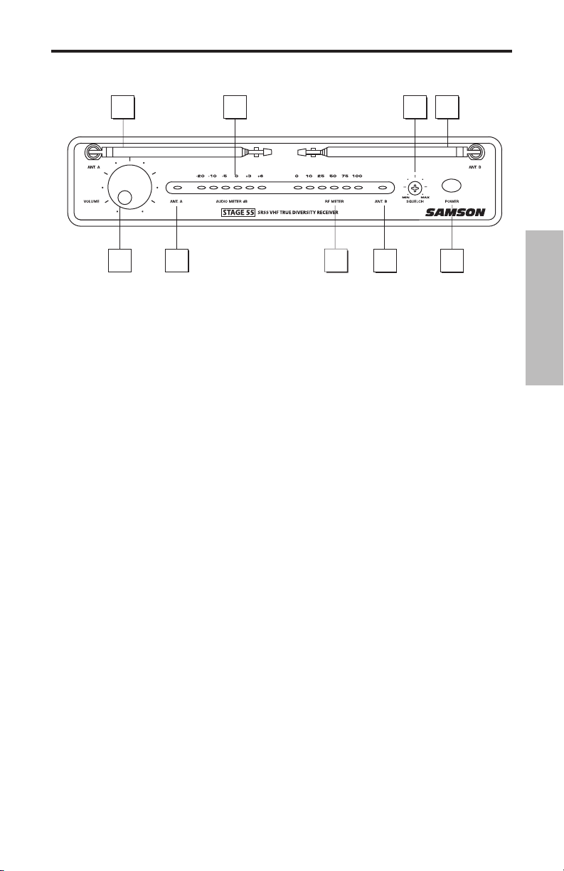
Guided Tour - SR55 Front Panel
1
2
3
4
5
5
1
7
6
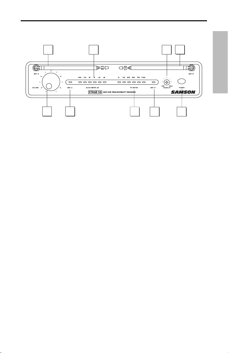
1: Antennas (A and B) - The antenna mountings allow full rotation for optimum placement. In
normal operation, both Antenna A (the antenna on the left) and Antenna B (the antenna on the
right) should be placed in a vertical position. Both antennas can be folded inward for convenience when transporting the SR55. See the “Setting Up and Using Your Stage 55 Series / Stage
5 Series System” section on page 12 in this manual for more information about antenna positioning.
2: Volume control - This knob sets the level of the audio signal being output through both the
balanced and unbalanced output jacks on the rear panel. Reference level is obtained when the
knob is turned fully clockwise.
3: Audio Meter - This “ladder” display (similar to the VU bar meter used on audio devices) indicates the strength of the incoming audio signal. When the “0” segment is lit, the incoming signal
is optimized at unity gain; when the “+6” segment is lit, the signal is overloading. When only the
left-most “-20” segment is lit, the incoming signal is at just 10% of optimum strength. If no segments are lit, little or no signal is being received. See the “Setting Up and Using Your Stage 55
Series / Stage 5 Series System” section on page 12 in this manual for more information.
ENGLISH
4: Squelch control - This control determines the maximum range of the SR55 before audio signal
dropout. Although it can be adjusted using the supplied plastic screwdriver, it should normally
be left at its factory setting. See the “Setting Up and Using Your Stage 55 Series / Stage 5 Series
System” section on page 12 in this manual for more information.
5: ANT A/B LEDs - When signal is being received, one of these will be lit yellow, showing you
whether the (left) “A” or (right) “B” antenna is currently being used. The SR55 constantly scans its
two antennas and automatically selects whichever is receiving the strongest, clearest signal. This
Diversity switching is completely inaudible, but it effectively increases overall range while virtually eliminating potential interference and phase cancellation problems.
6: RF Meter - This “ladder” display (similar to the VU bar meter used on audio devices) indicates
the strength of the incoming radio signal. When the “100%” segment is lit, the incoming RF signal
is fully modulated and at optimum strength. When only the second most left-most “10%” segment is lit, the incoming signal is at just 10% of optimum strength. If no segments are lit, little or
no signal is being received. See the “Setting Up and Using Your Stage 55 Series / Stage 5 Series
System” section on page 12 in this manual for more information.
7: Power switch - Use this to turn the SR55 power on and off.
3

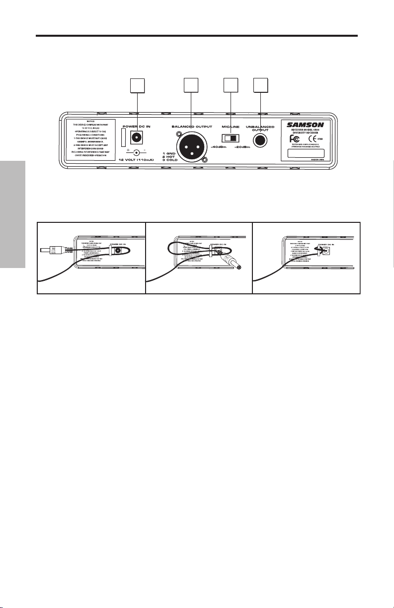
Guided Tour - SR55 Rear Panel
1
2
3
4
-
ENGLISH
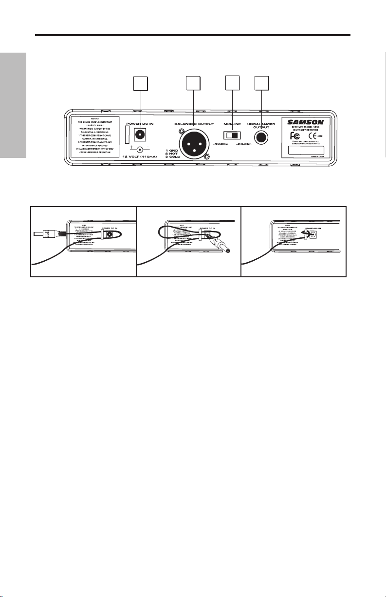
1: DC input - Connect the supplied 12 volt, 250 mA power adapter here, using the strain relief as
shown in the illustration below. WARNING: The substitution of any other kind of power adapter
can cause severe damage to the SR55 and will void your warranty.
Using the strain relief: Gather up a loop of wire and pass it through the strain relief,
then pass the adapter plug through the loop in order to create a knot.
2: Balanced output* - Use this electronically balanced low impedance (600 Ohm) XLR jack when
connecting the SR55 to professional (+4) audio equipment. Pin wiring is as follows: Pin 1 ground
(shield), Pin 2 high (hot), and Pin 3 low (cold).
3: Audio Output Level switch - Sets the audio output level attenuation of the balanced output
(see #4 below) to -20 dBm (line level) or -40 dBm (mic level). See the “Setting Up and Using Your
Stage 55 Series / Stage 5 Series System” section on page 12 in this manual for more information.
4: Unbalanced output* - Use this unbalanced high impedance (5K Ohm) 1/4" jack when con
necting the SR55 to consumer (-10) audio equipment. Wiring is as follows: tip hot, sleeve ground.
-
4
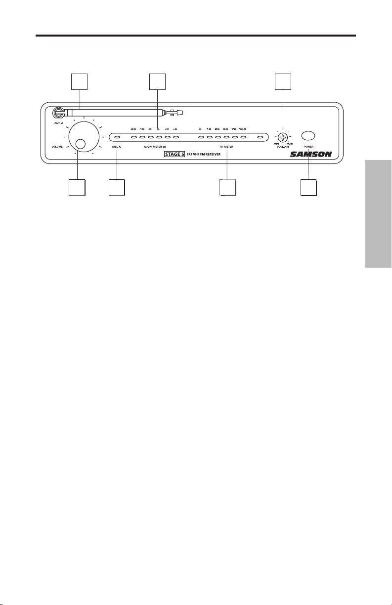
Guided Tour - SR5 Front Panel
1
2
3
4
5
7
6
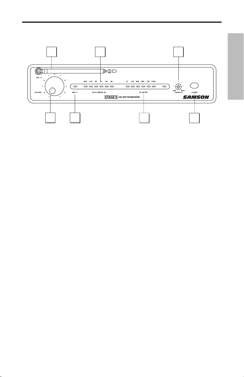
1: Antenna - The antenna mounting allows full rotation for optimum placement. In normal
operation, the antenna should be placed in a vertical position. It also can be folded inward for
convenience when transporting the SR5. See the “Setting Up and Using Your Stage 55 Series /
Stage 5 Series System” section on page 12 in this manual for more information about antenna
positioning.
2: Volume
balanced and unbalanced output jacks on the rear panel. Reference level is obtained when the
knob is turned fully clockwise.
control - This knob sets the level of the audio signal being output through both the
ENGLISH
3: Audio Meter - This “ladder” display (similar to the VU bar meter used on audio devices) indi
cates the strength of the incoming audio signal. When the “0” segment is lit, the incoming signal
is optimized at unity gain; when the “+6” segment is lit, the signal is overloading. When only the
left-most “-20” segment is lit, the incoming signal is at just 10% of optimum strength. If no seg
ments are lit, little or no signal is being received. See the “Setting Up and Using Your Stage 55
Series / Stage 5 Series System” section on page 12 in this manual for more information.
4: Squelch control - This control determines the maximum range of the SR5 before audio signal
dropout. Although it can be adjusted using the supplied plastic screwdriver, it should normally
be left at its factory setting. See the “Setting Up and Using Your Stage 55 Series / Stage 5 Series
System” section on page 12 in this manual for more information.
5: “TX” LED - Lights when carrier signal of sufficient strength is being received by the SR5.
6: RF Meter - This “ladder” display (similar to the VU bar meter used on audio devices) indicates
the strength of the incoming radio signal. When the “100%” segment is lit, the incoming RF signal
is fully modulated and at optimum strength. When only the second most left-most “10%” seg
ment is lit, the incoming signal is at just 10% of optimum strength. If no segments are lit, little or
no signal is being received. See the “Setting Up and Using Your Stage 55 Series / Stage 5 Series
System” section on page 12 in this manual for more information.
7: Power switch - Use this to turn the SR5 power on and off.
-
-
-
5
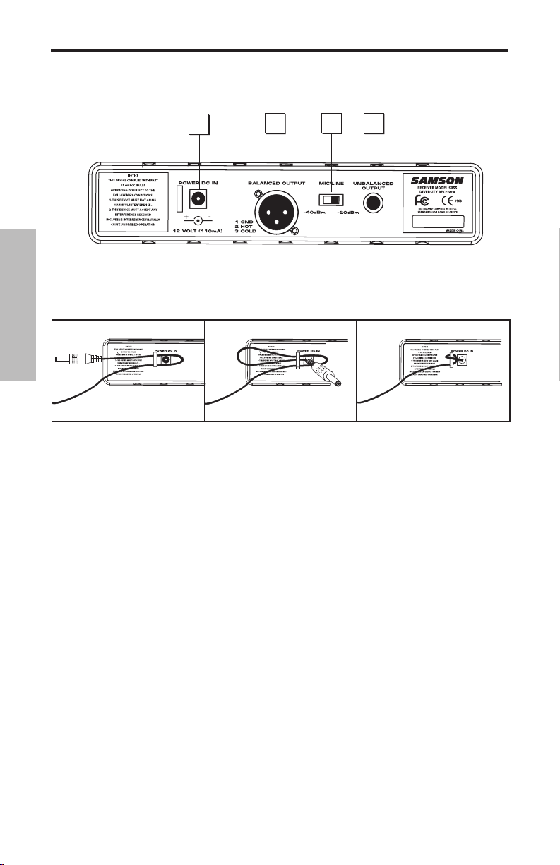
Guided Tour - SR5 Rear Panel
1
2
3
4
ENGLISH
1: DC input - Connect the supplied 12 volt, 250 mA power adapter here, using the strain relief
as shown in the illustration below. WARNING: The substitution of any other kind of power
adapter can cause severe damage to the SR5 and will void your warranty.
Using the strain relief: Gather up a loop of wire and pass it through the strain relief,
then pass the adapter plug through the loop in order to create a knot.
2: Balanced output* - Use this electronically balanced low impedance (600 Ohm) XLR jack
when connecting the SR5 to professional (+4) audio equipment. Pin wiring is as follows: Pin 1
ground (shield), Pin 2 high (hot), and Pin 3 low (cold).
3: Audio Output Level switch - Sets the audio output level attenuation of the balanced output
(see #4 below) to -20 dBm (line level) or -40 dBm (mic level). See the “Setting Up and Using Your
Stage 55 Series / Stage 5 Series System” section on page 10 in this manual for more information.
4: Unbalanced output* - Use this unbalanced high impedance (5K Ohm) 1/4" jack when con
necting the SR5 to consumer (-10) audio equipment. Wiring is as follows: tip hot, sleeve ground.
* If required, both the unbalanced and balanced outputs can be used simultaneously.
-
6
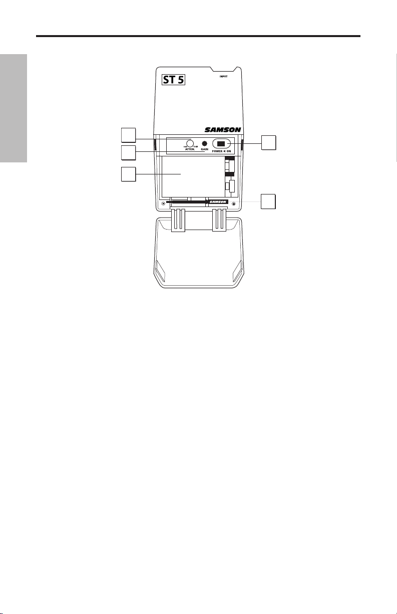
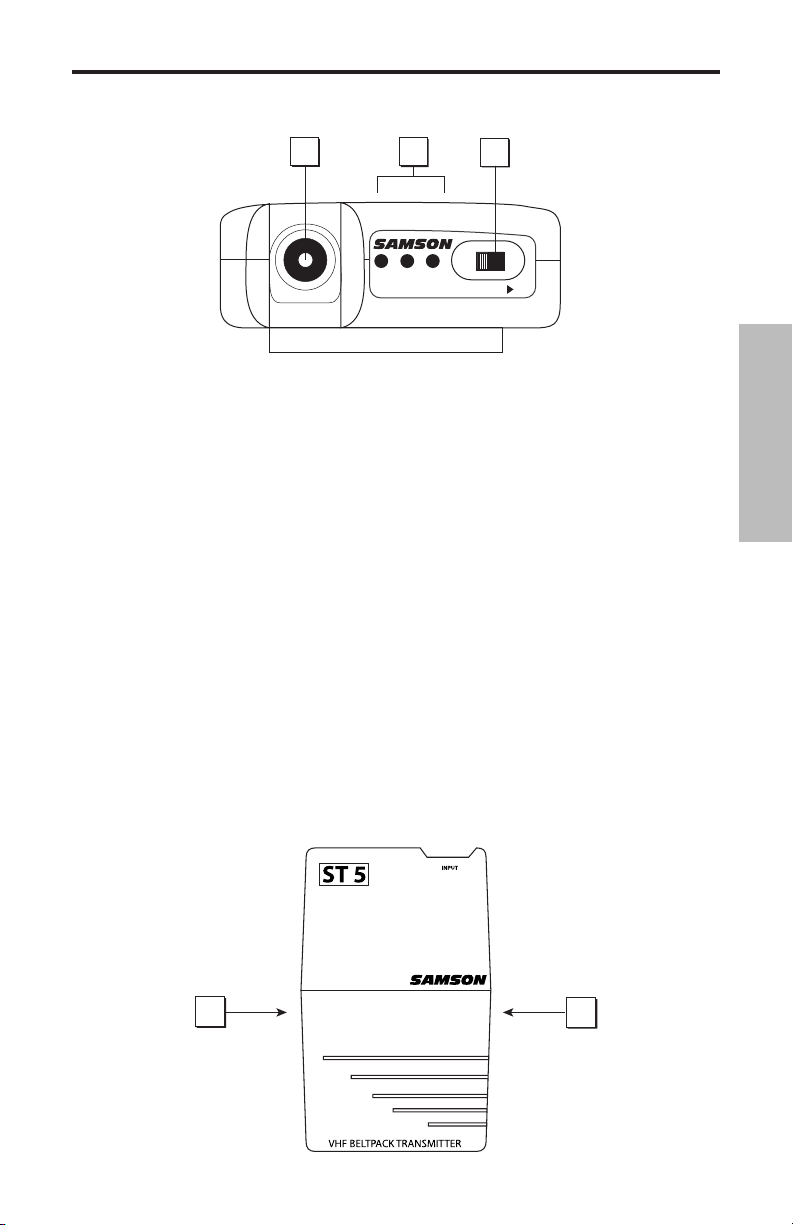
Guided Tour - ST5
1
2
3
AUDIO ON
LOW M
ID HIGH
BAT TER Y L EVE L
4
4
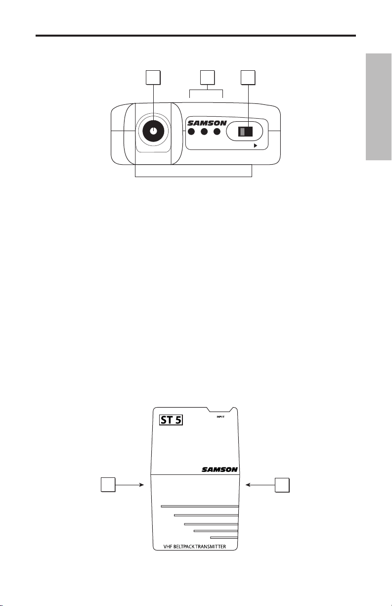
1: Input connector - The input device is connected here. The ST5 is supplied with either a lavaliere, headset microphone or heavy-duty instrument cable terminating with a 1/4" plug, which
are all connected to the transmitter via a locking 3.5mm mini-phone jack.
ENGLISH
2: Battery level meter - This set of three multicolor LEDs indicates relative battery power, indi
cating whether the installed battery is at low (red), mid (yellow) or high (green) strength. One or
more of these will light whenever the SR5 or ST5 is powered on (see #5 on the next page). When
all three are lit, the battery is at maximum strength. When only the red “low” indicator lights, RF
performance is degraded and the battery needs to be replaced.
3: Audio on-off switch - When set to the “on” position, audio signal is transmitted. When set
to the “off” position, the audio signal is muted. Because the carrier signal remains during mut
ing, no “pop” or “thud” will be heard. Note that turning this off does
power—it is simply a way to temporarily mute the transmission of audio signal. If you don’t
plan on using the transmitter for extended periods, turn off the transmitter power by using the
power on-off switch (see #5 on the next page).
4: Battery door release - Press gently inward on these two indents in order to open the battery
door of the ST5L or ST5 and access the Power on-off switch (see #5 on the next page) and Gain
control (see #6 on the next page).
5: Power on-off switch* - Use this to turn the ST5 on or off (to conserve battery power, be sure
to leave it off when not in use).
not turn off the transmitter
-
-
7
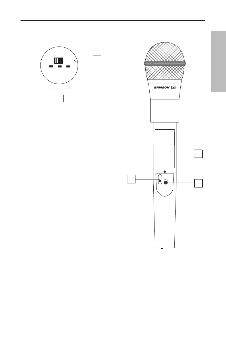
Guided Tour - ST5
9
8
5
6
7
ENGLISH
6: Attenuation switch - The ST5 transmitter features a signal Attenuation switch that is used
to select the input level of “0dB” or “-15dB”. This Attenuation switch has been factory preset to
“0dB” providing the optimum level for most microphone and instrument input signals. If you are
using a microphone or instrument with a high output signal, first try to adjust the Gain control as
described in the following section. If you cannot attenuate the signal low enough using the Gain
control, use the supplied plastic screwdriver (see #9 below) to turn the rotary Attenuation switch
to the counter-clockwise position setting the ST5 to “-15dB” level.
7: Gain control (trimpot) - This input gain control has been factory preset to a nominal level so
we recommend that this be adjusted only if your signal is too high, or too low. If necessary, however, you can use the supplied plastic screwdriver (see #9 below) to raise or lower the ST5 Gain
control. See the “Setting Up and Using Your Stage 55 Series / Stage 5 Series System” section on
page 12 in this manual for more information.
8: Battery holder - Insert a standard 9-volt alkaline battery here, being sure to observe the
plus and minus polarity markings shown. We recommend the Duracell MN 1604 type battery.
Although rechargeable Ni-Cad batteries can be used, they do not supply adequate current for
more than four hours. WARNING: Do not insert the battery backwards; doing so can cause
severe damage to the ST5 and will void your warranty.
9: Plastic screwdriver - Specially designed for use in adjusting the ST5 Gain control (see #7
above) and/or receiver Squelch control (see #4 on pages 5 and 7). See the “Setting Up and Using
Your Stage 55 Series / Stage 5 Series System” section on page 12 in this manual for more information.
* Be sure to mute the audio signal at your external mixer or amplifier before turning transmitter power
on or off, or an audible pop may result.
8
Guided Tour - HT5
MIN
MAX
LEVEL
POWER
ON
OFF
5
3
4
1
AUDIO
LOW MID HIGH
BATTERY LEVEL
Ch2
OFF ON
2
F
C
C
I
D
C
C
R
H
T
5
0
1
6
8
1: Audio on-off switch - When set to the “on” position, audio signal is transmitted. When set to the “off”
position, the audio signal is muted. Because the car
rier signal remains during muting, no “pop” or “thud”
will be heard. Note that turning this off does
turn off the transmitter power—it is simply a way to
temporarily mute the transmission of audio signal. If
you don’t plan on using the HT5 for extended periods,
turn off its power by using the power on-off switch
(see #3 below).
2: Battery level meter - This set of three multicolor
LEDs indicates relative battery power, indicating
whether the installed battery is at low (red), mid
(yellow) or high (green) strength. One or more of
these will light whenever the HT5 is powered on (see
#3 below). When all three are lit, the battery is at
maximum strength. When only the red “low” indicator
lights, RF performance is degraded and the battery
needs to be replaced.
3: Power on-off switch* - Use this to turn the HT5 on
or off (to conserve battery power, be sure to leave it
off when not in use).
4: Gain control (trimpot) - This input sensitivity con
trol has been factory preset to provide optimum level
for the particular microphone capsule provided with
your Stage 55 Series or Stage 5 Series system and so we recommend that this not be adjusted
manually. If necessary, however, you can use the supplied plastic screwdriver to raise or lower
the input level. See the “Setting Up and Using Your Stage 55 Series / STAGE 5 Series System” sec
tion on page 12 in this manual for more information.
5: Battery holder - Insert a standard 9-volt alkaline battery here, being sure to observe the
plus and minus polarity markings shown. We recommend the Duracell MN 1604 type battery.
Although rechargeable Ni-Cad batteries can be used, they do not supply adequate current for
more than four hours. WARNING: Do not insert the battery backwards; doing so can cause
severe damage to the HT5 and will void your warranty.
* Be sure to mute the audio signal at your external mixer or amplifier before turning transmitter
power on or off, or an audible pop may result.
-
not
-
ENGLISH
-
9

Setting Up and Using Your
Stage 55 Series/Stage 5 Series System
The basic procedure for setting up and using your Stage 55 Series or Stage 5 Series Wireless
System takes only a few minutes:
1. For the Stage 55 Series / Stage 5 Series system to work correctly, both the receiver and trans
mitter must be set to the same channel. Remove all packing materials (save them in case of need
for future service) and check to make sure that the supplied receiver and transmitter are set to
ENGLISH
the same channel. If these channels do not match, contact your distributor or, if purchased in
the United States, Samson Technical Support at 1-800-372-6766.
2. Physically place the receiver where it will be used (the general rule of thumb is to maintain
“line of sight” between the receiver and transmitter so that the person using or wearing the
transmitter can see the receiver). - Extend the antenna or antennas and place them in a vertical
position.
3. Make sure the Power on-off switch in your ST5 belt-pack or HT5 handheld transmitter is set to
“Off.”
4a. If your system contains a ST5 belt-pack transmitter, press gently inward on both battery
cover release indents to open the battery door. Note that this door is hinged and not intended
to be removed from the transmitter case. Please use care when opening this door as undue
force will destroy the hinge.
4b. If your system contains a HT5 handheld transmitter, unscrew the bottom section of the
microphone by turning it counterclockwise and then slide it off.
5. Place a fresh 9-volt alkaline battery in the transmitter battery holder, taking care to observe
the polarity markings. If you are using a ST5 belt-pack transmitter, gently replace the battery
door by swinging it up and pressing until it clicks. If you are using a HT5 handheld transmitter,
replace the bottom section of the microphone by sliding it on and then screwing it back on.
Whichever transmitter you are using, leave it off for the moment.
6. Make the physical cable connection between the SR55 or SR5 output jack and the line or mic
level audio input of your amplifier or mixer. If you are using the balanced XLR jack (preferable,
since it will deliver an electromagnetically cleaner signal), be sure to set the receiver rear panel
Audio Output Level switch correctly.If required, both the balanced and unbalanced outputs can
be used simultaneously. Leave your amplifier (and/or mixer) off at this time.
7. Turn the Volume knob on the SR55 or SR5 completely counterclockwise. Using the strain
relief, connect the supplied AC adapter to the DC Input on the rear panel of the SR55 or SR5,
then plug the adapter into any standard AC outlet. Press the front panel Power switch to turn
on the SR55 or SR5; the green “Power” LED will light up, but all other front panel LEDs will remain
unlit.
8. Turn on the power to the ST5 or HT5 transmitter (using its Power on-off switch); all three
Battery strength LEDs will light if the battery is sufficiently strong. At this point, the RF Meter
on the front panel of the receiver will light. If you are using an SR55 receiver, either the “A” or “B”
yellow LED on the front panel will also light, depending upon which antenna is receiving the
stronger signal.
-
10
Setting Up and Using Your
Stage 55 Series/Stage 5 Series System
9. Now it’s time to set the audio levels. Turn on your connected amplifier and/or mixer but keep
its volume all the way down. Next, make sure that your transmitter is unmuted by setting its
Audio switch to “On.” Then set the Volume knob on the SR55 or SR5 fully counterclockwise. If you
are using the HT5 transmitter or if you are using the ST5 transmitter with a connected lavaliere
microphone or headset, speak or sing into the mic at a normal performance level while observing
the SR55 or SR5 front panel Audio Meter. If you are using the ST5 transmitter with a connected
instrument, play the instrument at normal performance level while observing the SR55 or SR5
front panel Audio Meter. If the “0” (unity gain) segment is lighting steadily, with just occasional
higher excursions, the audio level is correctly set. If not, use the supplied plastic screwdriver to
slowly adjust the HT5, or ST5 Gain control (trimpot) until the SR55 or SR5 Audio Meter “0” (unity
gain) segment lights steadily (with occasional higher excursions). Then slowly raise the SR55 or
SR5 Volume knob to the 2 o’clock position (unity gain) and, finally, set the volume of your ampli
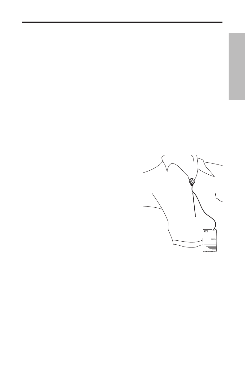
fier/mixer until the desired level is reached. If you are using a ST5 beltpack transmitter equipped
with a lavaliere microphone, note that correct lavaliere placement is critical to sound quality. We
recommend that you place it as shown in the illustration on the right—as close to your mouth as
possible but off to one side (to minimize nasality) and unobstructed by clothing. Bear in mind
omni microphones (mics which pick up signal
also that
from all directions) are more prone to feedback problems
than unidirectional (cardioid or supercardioid) ones; in
general, you can avoid feedback by taking care not to use
any microphone directly in front of a PA speaker (if this is
unavoidable, try using an equalizer to attenuate those
high- or mid-range frequencies which are causing the
feedback “squealing”).
10. If you hear distortion at the desired volume level (or
if the “+6” segment LED in the Audio Meter is lighting fre
quently), first check that the SR55 or SR5 rear panel Audio
Output Level switch is set correctly. Next, make sure that
the gain structure of your audio system is correctly set
(consult the owners manual of your mixer and/or amplifi
er for details). If you still hear distortion, do the following:
• If you are using a HT5 handheld transmitter or an
ST5 transmitter with connected lavaliere micro
phone or headset, its Gain control has been factory preset to provide optimum level for the
particular microphone model being used and so no adjustment should be necessary. Any
distortion present should therefore simply be a matter of the microphone being too close to
the mouth; try moving it further away. If this does not solve the problem, use the supplied
plastic screwdriver to turn the Gain control (trimpot) on the HT5 or ST5 slowly counterclock
wise until the distortion disappears.
• If you are using a ST5 transmitter with an instrument such as electric guitar or bass, lower
the output level of the instrument until the distortion disappears. Alternatively, you can use
the supplied plastic screwdriver to turn the Gain control (trimpot) on the ST5 slowly coun
terclockwise until the distortion disappears.
Note that, following this setup procedure, you can always lower the Volume knob of the SR55 or
SR5 in order to further attenuate the output signal if necessary.
-
-
-
-
-
ENGLISH
-
11. Conversely, if you hear a weak, noisy signal at the desired volume level (and with the Volume
control of the receiver turned fully clockwise), again make sure that the SR55 or SR5 rear panel
Audio Output Level switch is set correctly and that the gain structure of your audio system is
11

Setting Up and Using Your
Stage 55 Series/Stage 5 Series System
correctly set. If it is and the signal coming from the SR55 or SR5 is still weak and/or noisy, do the
following:
• If you are using a HT5 transmitter or an ST5 transmitter with connected lavaliere micro
phone or headset, its Gain control has been factory preset to provide optimum level for the
ENGLISH
particular microphone model being used and so no adjustment should be necessary. Any
weakness of signal should therefore simply be a matter of the microphone being too far
from the mouth; try moving it closer. If this does not solve the problem, use the supplied
plastic screwdriver to turn the Gain control (trimpot) on the HT5 or ST5 slowly clockwise
until the signal reaches an acceptable level.
• If you are using a ST5 transmitter with an instrument such as electric guitar or bass, raise the
output level of the instrument until a good signal is achieved. Alternatively, you can use the
supplied plastic screwdriver to turn the Gain control (trimpot) on the ST5 slowly clockwise
until the signal reaches an acceptable level.
12. Temporarily turn down the level of your mixer/amplifier system and turn off the power to
your transmitter, leaving the SR55 or SR5 on. Then restore the previously set level of your mixer/
amplifier. With the transmitter off, the receiver output should be totally silent—if it is, skip ahead
to the next step. If it isn’t (that is, if you hear some noise), you may need to adjust the receiver’s
front panel Squelch control. When the Squelch control is at its minimum setting, the Stage
55 Series / Stage 5 Series system always provides maximum range without dropout; however,
depending upon the particular environment your system is used in, you may need to reduce that
range somewhat in order to eliminate band noise or interference when the transmitter is turned
off. To do so, use the provided screwdriver to rotate the Squelch control completely counter
clockwise (to the “Min” position), then slowly turn it clockwise until the noise disappears. If no
noise is present at any position, leave it at its fully counterclockwise “Min” position (so as to have
the greatest overall range available).
-
-
13. When first setting up the Stage 55 Series or Stage 5 Series System in a new environment, it’s
always a good idea to do a walkaround in order to make sure that coverage is provided for your
entire performance area. Accordingly, turn down the level of your audio system and turn on both
the transmitter and receiver. Then, with the transmitter unmuted, restore the level of your audio
system and while speaking, singing, or playing your instrument, walk through the entire area that
will need to be covered. As you do so, the “TX” LED on the front panel of the SR55 or SR5 should
always remain lit. If you are using a Stage 55 Series system, one of the yellow “A” and “B” LEDs on
the SR55 receiver should always be lit, though occasionally switching to show you which antenna
is receiving the stronger signal. Always try to minimize the distance between transmitter and
receiver as much as possible so that the strongest possible signal is received from all planned
transmission points. In fixed installations such as A/V or corporate conference rooms or for
extended range applications (where the transmitter and receiver are more than 150 feet apart), it
may be desirable to angle the receiver antenna or antennas differently from their vertical position
or to install the receiver in the same room as the transmitters (and, if necessary, to extend the
wiring to remote audio equipment).
If you have followed all the steps above and are experiencing difficulties, contact your local dis
tributor or, if purchased in the United States, call Samson Technical Support (1-800-372-6766)
between 9 AM and 5 PM EST.
-
12

Introduction
Merci d'avoir fait confiance au système sans fil VHF Samson VHF TD Series ou VHF Series ! Ces
deux produits sont très simples d'emploi, mais nous vous conseillons tout de même de lire ces
quelques pages pour tirer parti de tout leur potentiel.
Un système sans fil est composé d'au moins deux éléments (émetteur et récepteur) qui doivent
être réglés sur le même canal (sur la même haute fréquence) pour fonctionner correctement.*
Le système Samson VHF TD Series ou VHF Series que vous avez acquis fonctionne sur une plage
de fréquence de 173,8 à 213,2 MHz et est équipé d'un récepteur VR3TD ou VR3 ainsi que l'un
des émetteurs suivants : émetteur de ceinture VT3L (pour les microphones cravate et serre-tête),
émetteur de ceinture VT3 (pour instruments) ou microphone main VH3. Pour davantage de
sécurité et pour faciliter leur transport, les systèmes VHF TD Series et VHF Series sont livrés dans
un boîtier antichoc en plastique polypropylene (voir Annexe B, page 50 pour de plus amples
détails).
L’émetteur de ceinture ST5L est équipé d’un connecteur mini-Jack 3,5 mm permettant l’utilisation
des divers émetteurs de la série Stage, dont :
LM5 – Micro cravate à condensateur
HS5 - Micro serre-tête à condensateur
GC5 – Câble guitare/instrument haute résistance
L’émetteur micro main HT5 est équipé de la capsule dynamique Samson Q7 au néodyme.
* L'émetteur et le récepteur ont été réglés d'usine sur le même canal.
FRANÇAIS
** Optimisé pour les applications sportives, l'utilisation de ce micro serre-tête étanche est recomman
dée en environnement très humide comme les salles de sport et les centres de remise en forme.
13
-

Introduction
Le récepteur VR3 du système sans fil VHF Series fait appel à la technologie non-diversity, incorpore une seule antenne pour une plus grande simplicité d'emploi et des coûts plus faibles. Le
récepteur SR55 fourni avec le système Stage 55 Series utilise une technologie avancée appelée
“Diversity”. Le récepteur intègre deux antennes (“Antenne A” et “Antenne B”) et un circuit de
réception. Le circuit haute technologie scanne en permanence les signaux HF avec les deux
antennes et détermine quelle antenne offre la réception la plus claire et la plus puissante
— c’est ce signal qui est alors transmis (sans bruit de commutation) au récepteur. Ce procédé
permet d'obtenir une portée de la liaison sans fil bien plus grande que ne pourrait l'offrir un
récepteur utilisant une seule antenne et supprime également les problèmes de perte de sig
nal, d'interférences et de déphasage. En outre, le circuit de liaison sample-and-hold assure en
permanence une bonne corrélation de phase sans bruit et sans pop lors de la commutation
de l'antenne. Vous obtenez des performances bien supérieures aux systèmes d'antenne true
diversity et une qualité sonore de haute fidélité quel que soit le système sans fil utilisé. Enfin, le
réducteur de bruit Signetics permet d'offrir un son très clair avec un bruit de fond et un siffle
ment réduits au minimum.
Ce manuel vous donne une description détaillée des caractéristiques et fonctions des systèmes
FRANÇAIS
VHF TD Series et VHF Series, un petit tour d'horizon des éléments qui les composent, les con
signes de configuration et d'utilisation de votre système et leurs caractéristiques techniques. Si
vous avez acquis votre système VHF TD Series ou VHF Series aux Etats-Unis, remplissez la carte
de garantie fournie et retournez-la nous. Vous pourrez ainsi bénéficier de l'assistance technique
en ligne et recevoir les dernières informations sur les produits Samson. Si vous avez acquis votre
système VHF TD Series ou VHF Series hors des Etats-Unis, contactez votre revendeur local.
-
-
-
14
Tour d'horizon - Façade avant du SR55
1
2
3
4
5
5
1
7
6
1 : Antennes (A et B) - Les antennes pivotent pour une placement optimal. En fonctionnement
normal, l'antenne A (celle de gauche) et l'antenne B (celle de droite) doivent être placées à la
verticale. Vous pouvez replier les antennes pour faciliter le transport du VR3TD. Reportez-vous
au chapitre "Réglage et utilisation du système VHF TD Series / VHF Series", page 22, pour de plus
amples détails sur le placement des antennes.
2 : Potentiomètre de volume - Ce potentiomètre permet d'ajuster le niveau des signaux audio
envoyés aux sorties symétrique et asymétrique de la façade arrière. Tournez-le au maximum vers
la droite pour obtenir le niveau de référence.
3 : Afficheur de niveau audio - Cet afficheur (similaire aux Bargraphs utilisés sur les équipe
ments audio) indique le niveau du signal d’entrée audio. Lorsque le segment “0” est allumé, le
niveau du signal d’entrée est optimisé à gain unitaire ; lorsque le segment “+6” est allumé, le
signal sature. Lorsque seul le segment de gauche “-20” est allumé, le niveau du signal d’entrée
n’est qu’à 10 % de son niveau optimal. Si aucun segment n’est allumé, quasiment aucun signal
n’est reçu. Consultez la section “Configuration et utilisation du système Stage 55 Series / Stage
5_Series” en page 12 de ce mode d’emploi pour obtenir de plus amples informations.
4 : Réglage de squelch - Ce réglage permet de définir la portée maximale du VR3TD avant perte
du signal audio. Même si vous pouvez l'ajuster à l'aide du tournevis en plastique fourni, il est
recommandé de ne pas toucher au réglage d'usine. Reportez-vous au chapitre "Réglage et utilisa
tion du système VHF TD Series / VHF Series", page 22, pour de plus amples détails.
5 : Témoins A/B - Un des deux témoins (correspondant à l'antenne en action, A pour l'antenne
A de gauche et B pour l'antenne B de droite) s'allume en jaune lors de la réception des signaux.
Le VR3TD examine en permanence les deux antennes et sélectionne automatiquement celle qui
reçoit le signal le plus puissant et le plus clair. La commutation du système Diversity est totale
ment silencieuse, mais elle permet d’augmenter la portée en éliminant quasiment tous les prob
lèmes d’interférence et de déphasage.
6 : Afficheur de niveau HF - Cet afficheur (similaire au VU-mètre des appareils audio) vous
indique la force du signal audio reçu. Lorsque le segment “100%” est allumé, le signal HF reçu
est totalement modulé et à niveau optimal. Lorsque seul le segment "10 %" le plus à gauche
s'allume, cela signifie que le signal d'entrée est à 10 % de sa puissance optimale. Si aucun seg
ment ne s'allume, cela signifie qu'aucun signal n'est reçu ou seulement un signal très faible.
Reportez-vous au chapitre "Réglage et utilisation du système VHF TD Series / VHF Series", page 22,
pour de plus amples détails.
7 : Interrupteur d'alimentation Power - Il permet des mettre sous et hors tension le VR3TD. Le
témoin d'alimentation s'allume en verte lorsque l'appareil est sous tension.
-
-
-
FRANÇAIS
-
-
15
Tour d'horizon - Façade arrière du SR55
1
2
3
4
1 : Connecteur d'alimentation - Reliez-y l'adaptateur 12 volts 250 mA fourni en veillant à bien
faire le noeud de sécurité comme le montre l'illustration ci-dessous.
AVERTISSEMENT : L'utilisation d'un adaptateur non conforme peut endommager gravement le
VR3TD et annulerait la garantie.
FRANÇAIS
Noeud de sécurité : Faites une boucle avec le cordon et faites la passer dans la sécurité, puis faites
2 : Sortie asymétrique* - Cette sortie asymétrique haute impédance (5 kOhms) au format
jack 6,35 mm vous permet de relier le VR3TD à des appareils audio de type domestique (-10).
Câblage : point chaud sur pointe, masse sur corps.
3 : Sélecteur de niveau de sortie audio - Permet d'atténuer le niveau de la sortie symétrique de
-20 dBm (niveau ligne) ou -40 dBm (niveau micro). Reportez-vous au chapitre "Réglage et utili
sation du système VHF TD Series / VHF Series", page 22, pour de plus amples détails.
4 : Sortie symétrique* - Cette sortie symétrique basse impédance (600 Ohms) au format XLR
vous permet de relier le VR3TD à des appareils audio de type professionnel (+4). Câblage : masse
(blindage) sur broche 1, point chaud sur broche 2 et point froid sur broche 3.
* Vous pouvez utiliser simultanément la sortie symétrique et la sortie asymétrique.
passer la prise du cordon dans la boucle de façon à obtenir un noeud.
-
16
Tour d'horizon - Façade avant du SR5
1
2
3 4
5 7
6
FRANÇAIS
1 : Antenne - L'antenne pivote pour une placement optimal. En fonctionnement normal,
l'antenne doit être placée à la verticale mais vous pouvez la replier pour transporter plus fac
ilement le VR3. Reportez-vous au chapitre "Réglage et utilisation du système VHF TD Series /
VHF Series", page 22, pour de plus amples détails sur le placement des antennes.
2 : Potentiomètre de volume - Ce potentiomètre permet d'ajuster le niveau des signaux audio
envoyés aux sorties symétrique et asymétrique de la façade arrière. Tournez-le au maximum vers
la droite pour obtenir le niveau de référence.
3 : Témoin "TXON" - S'allume lorsqu'un signal de porteuse suffisamment puissant est reçu par le
VR3.
4 : Réglage de Squelch - Ce réglage permet de définir la portée maximale du VR3 avant perte
du signal audio. Même si vous pouvez l'ajuster à l'aide du tournevis en plastique fourni, il est
recommandé de ne pas toucher au réglage d'usine. Reportez-vous au chapitre "Réglage et utilisa
tion du système VHF TD Series / VHF Series", page 22, pour de plus amples détails.
5 : Afficheur de niveau audio - Cet afficheur (similaire au VU-mètre des appareils audio) vous
indique la puissance du signal audio reçu. Lorsque le segment "100 %" s'allume, le signal
d'entrée est optimisé au gain unitaire ; lorsque le segment "125 %" s'allume, le signal surcharge.
Lorsque seul le segment "10 %" le plus à gauche s'allume, cela signifie que le signal d'entrée est à
10 % de sa puissance optimale. Si aucun segment ne s'allume, cela signifie qu'aucun signal n'est
reçu ou seulement un signal très faible. Reportez-vous au chapitre "Réglage et utilisation du sys
tème VHF TD Series / VHF Series", page 22, pour de plus amples détails.
6 : Afficheur de niveau HF - Ce témoin s'allume en verte lorsque vous mettez le VR3 sous ten
sion.
7 : Interrupteur d'alimentation Power - Il permet de mettre sous et hors tension le VR3. Le
témoin d'alimentation s'allume en verte lorsque l'appareil est sous tension.
-
-
-
-
17
Tour d'horizon - Façade arrière du SR5
1
2
3
4
-
1 : Connecteur d'alimentation - Reliez-y l'adaptateur 12 volts 250 mA fourni en veillant à bien
faire le noeud de sécurité comme le montre l'illustration ci-dessous.
FRANÇAIS
Noeud de sécurité : Faites une boucle avec le cordon et faites la passer dans la sécurité, puis faites passer la prise du
AVERTISSEMENT : L'utilisation d'un adaptateur non conforme peut endommager gravement le
VRX et annulerait la garantie.
2 : Sortie asymétrique* - Cette sortie asymétrique haute impédance (5 kOhms) au format jack
6,35 mm vous permet de relier le VRX à des appareils audio de type domestique (-10). Câblage :
point chaud sur pointe, masse sur corps.
3 : Sélecteur de niveau de sortie audio - Permet d'atténuer le niveau de la sortie symétrique
de -20 dBm (niveau ligne) ou -40 dBm (niveau micro). Reportez-vous au chapitre "Réglage et
utilisation du système VHF TD Series / VHF Series", page 22, pour de plus amples détails.
4 : Sortie symétrique* - Cette sortie symétrique basse impédance (600 Ohms) au format XLR
vous permet de relier le VRX à des appareils audio de type professionnel (+4). Câblage : masse
(blindage) sur broche 1, point chaud sur broche 2 et point froid sur broche 3.
* Vous pouvez utiliser simultanément la sortie symétrique et la sortie asymétrique.
cordon dans la boucle de façon à obtenir un noeud.
18
Tour d'horizon - SR5 / ST5
1
2
3
AUDIO ON
LOW M
ID HIGH
BAT TER Y L EVE L
4
4
1 : Connecteur d’entrée – Le capteur utilisé est connecté à cette embase. Le ST5 est fourni
avec un micro cravate, un micro serre-tête ou un câble instrument haute résistance en Jack 6,35
mm, connectés à l’émetteur par un mini-Jack 3,5 mm à verrouillage.
2 : Témoins d'usure de la pile - Ces trois diodes vous renseignent sur l'usure de la pile : la diode
rouge s'allume lorsque la pile doit être changée, la diode jaune s'allume lorsque vous avez
consommé la moitié de la pile et la diode verte s'allume lorsque la pile est neuve ou presque.
Une de ces trois diode clignote lors de la mise sous tension du VT3L/VT3 (voir n°5 de la page
suivante). Lorsque la diode rouge "low" clignote, les performances RF baissent et il faut changer
la pile.
3 : Interrupteur Audio - Lorsqu'il est placé sur "on", les signaux audio sont transmis. Lorsqu'il
est placé sur "off", la transmission est coupée. Comme le signal de porteuse reste actif lorsque
la transmission est coupée, aucun bruit parasite n'apparaît. Attention : le fait de faire basculer
l'interrupteur sur "off" ne met pas l'émetteur hors tension (cela coupe simplement la transmis
sion des signaux audio). Si vous prévoyez de ne pas utiliser l'émetteur pendant une période pro
longée, éteignez-le à l'aide de l'interrupteur d'alimentation Power. (voir n°5 de la page suivante).
4 : Ouverture du compartiment de la pile - Poussez délicatement la trappe tout en appuyant
légèrement sur les deux encoches afin d'ouvrir le compartiment de la pile du VT3L/VT3. Vous
avez ainsi accès à l'interrupteur d'alimentation (voir n°5 de la page suivante) et au potentiomètre
de gain (voir n°6 de la page suivante).
5 : Interrupteur d'alimentation Power* - Il permet de mettre sous et hors tension les VT3L
et VT3. Pour ne pas gaspiller inutilement la pile, veillez à bien mettre le VT3L/VT3 hors tension,
position "off", lorsque vous ne l'utilisez pas.
-
FRANÇAIS
-
19
 Loading...