

Page 1

10-Channel Rack Mount Line Mixer
Owner’s Manual
www.samsontech.com
Page 2

Copyright 2017, Samson Technologies Corp. v2.1
Samson Technologies Corp.
278-B Duffy Ave
Hicksville, NY 11801
www.samsontech.com
Page 3
Important Safety Information
RISQUE DE CHOC ÉLECTRONIQUE -
AVIS
NE PAS OUVRIR
CAUTION: TO REDUCE THE RISK OF ELECTRIC SHOCK, DO NOT REMOVE COVER (OR
BACK). NO USER-SERVICEABLE PARTS INSIDE. REFER SERVICING TO QUALIFIED
SERVICE PERSONNEL.
This lightning flash with arrowhead symbol within an equilateral triangle is
intended to alert the user to the presence of non-insulated “dangerous voltage”
within the product’s enclosure that may be of sufficient magnitude to constitute
a risk of electric shock.
The exclamation point within an equilateral triangle is intended to alert the user
to the presence of important operating and maintenance instructions in the
literature accompanying the appliance.
If you want to dispose this product, do not mix it with general household waste.
There is a separate collection system for used electronic products in accordance
with legislation that requires proper treatment, recovery and recycling.
Private household in the 28 member states of the EU, in Switzerland and Norway
may return their used electronic products free of charge to designated collection facilities or
to a retailer (if you purchase a similar new one).
For Countries not mentioned above, please contact your local authorities for a correct
method of disposal.
By doing so you will ensure that your disposed product undergoes the necessary treatment,
recovery and recycling and thus prevent potential negative effects on the environment and
human health.
ENGLISH
FRANÇAISDEUTSCHEESPAÑOL
SM10 3
Page 4

Important Safety Information
1. Read these instructions.
2. Keep these instructions.
3. Heed all warnings.
4. Follow all instructions.
5. This apparatus shall not be exposed
to dripping or splashing liquid and no
object filled with liquid, such as a vase,
should be placed on the apparatus.
6. Clean only with a dry cloth.
7. Do not block any of the ventilation
openings. Install in accordance with
the manufacturer's instructions.
8. Do not install near any heat sources
such as radiators, heat registers,
stoves, or other apparatuses (including
amplifiers) that produce heat.
9. Only use attachments/accessories
specified by the manufacturer.
10. Unplug this apparatus during lightning
storms or when not in use for long
periods of time.
11. Do not override the intended purpose
of the polarized or grounding-type plug.
A polarized plug has two blades, with
one wider than the other. A groundingtype plug has two blades and a third
grounding prong. The wide blade, or
third prong, is provided for your safety.
If the provided plug does not fit your
outlet, consult an electrician to replace
the obsolete outlet.
12. Protect the power cord from being
walked on or pinched, particularly at
the prongs, convenience receptacles,
the point where they exit from the
apparatus.
13. Use only with the cart stand, tripod
bracket, or table specified by the
manufacture, or sold with the
apparatus. When a cart is
used, utilize caution when
moving the cart/apparatus
combination to avoid
injury from tip-over.
14. Refer all servicing to qualified service
personnel. Servicing is required if the
apparatus has been damaged in any
way, such as power-supply cord or
plug breakage, damage due to liquid
or objects falling onto the apparatus,
exposure to rain or moisture, or if the
apparatus does not operate normally, or
has been dropped.
15. POWER ON/OFF SWITCH: For products
with a power switch, the power switch
DOES NOT break the connection from
the mains.
16. MAINS DISCONNECT: The plug should
remain readily operable. For rackmount or installation where plug is not
accessible, an all-pole mains switch
with a contact separation of at least
3mm in each pole shall be incorporated
into the electrical installation of the
rack or building.
17. FOR UNITS EQUIPPED WITH
EXTERNALLY ACCESSIBLE FUSE
RECEPTACLE: Replace fuse with same
type and rating only.
18. MULTIPLE-INPUT VOLTAGE: This
equipment may require the use of a
different line cord, attachment plug, or
both, depending on the available power
source at installation. Connect this
equipment only to the power source
indicated on the equipment rear panel.
To reduce the risk of fire or electric
shock, refer servicing to qualified
service personnel or equivalent.
4
Page 5

Introduction
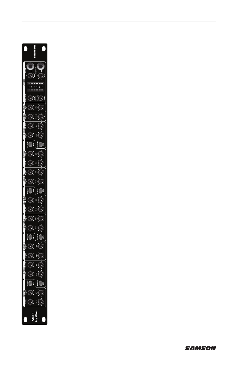
The Samson SM10 rack mount mixer is a versatile tool for many sound
applications. The SM10 mixer features eight independent stereo line input
channels, and includes two channels with XLR microphone preamps. There are
also two additional line inputs with stereo 1/4” jacks and level controls that can
be used to daisy-chain SM10 mixers together. The SM10 features a multitude of
signal routing options, with Monitor (Pre-Fade), EFX (Post-Fade), and Mix B sends
on Channels 1-8. The Master section of the SM10 features expanded monitoring
capabilities. The headphone output and meter bridge can be selected to monitor
the MON out, EFX out, Mix B, or Main output. There is also an extra MON output
with level control for quick patching to the MON send without having to go to the
rear panel. Built into a single space 19-inch rack with internal power supply, the
SM10 is reliable for any installation and rugged enough to be used on the road.
In these pages, you’ll find a detailed description of the features of the SM10 rack
mount mixer, as well as a guide to its control panel, instructions for setup and use,
and full specifications. You’ll also find a warranty card enclosed. Please don’t forget
to fill it out and mail it in so that you can receive online technical support, and so
that we can send you updated information about this and other Samson products
in the future. Also, be sure to check out our website (www.samsontech.com) for
information about our full product line.
With proper care, your SM10 will operate trouble-free for many years. We
recommend you record your serial number in the space provided below for future
reference.
ENGLISH
FRANÇAISDEUTSCHEESPAÑOL
Serial number: ____________________________________________
Date of purchase: __________________________________________
Should your unit ever require servicing, a Return Authorization number (RA) must
be obtained before shipping your unit to Samson. Without this number, the unit
will not be accepted. Please call Samson at 1-800-3SAMSON (1-800-372-6766)
for an RA number prior to shipping your unit. Please retain the original packing
materials and if possible, return the unit in the original carton and packing
materials. If you purchased your Samson product outside the United States,
please contact your local distributor for warranty information and service.
SM10 5
Page 6
Features
The Samson SM10 rack mount mixer is a comprehensive all-inone solution for fixed installation, live sound, on-stage monitoring,
keyboard submixer and recording applications. Here are some of its
main features:
• 10 input channels – Two Mic/Line plus ten stereo line
• Low noise, discrete microphone pre-amplifiers with 48-Volt
phantom power.
• Versatile signal routing via Main Mix, Mix B, Mon, EFX bus
outputs, as well as mono output.
• Balance controls for each channel that allow you to blend the
relative levels of stereo inputs.
• Two auxiliary sends can be used to route signals to external
effects, or to create a separate mix for on-stage monitors.
• Front-panel headphone and mono output jack with dedicated
level controls
• Flexible headphone and six-segment LED meter source control
allows you to monitor the MON, EFX, MIX B and MAIN MIX
• Line Input Level switch for +4 dBu or -10 dBV line level input
signals.
• Electronically balanced main stereo XLR and 1/4” line outputs.
• Center detents for all input controls, for use in low-light
situations such as live performance.
• Single 19” rack-mount metal chassis with internal power supply,
easily integrated into any existing system.
• Quality built and rugged construction ensure reliable performance
from venue to venue and session to session.
6
Page 7
Controls and Functions
21
5
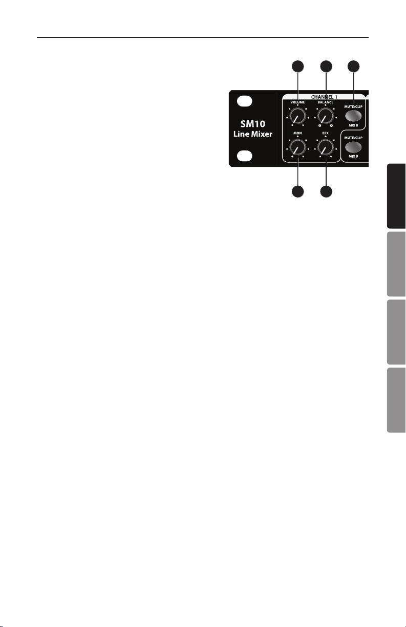
1. VOLUME – This knob controls the volume of
channel inputs and is used to continuously
adjust the loudness of the various signals
being blended together at the Main
Outputs. There is a detent at the 12 o’clock
position of the knob, which indicates unity
gain.
Moving the knob counterclockwise from the
12 o’clock position causes the signal to be
attenuated. Moving it clockwise from the
12 o’clock position causes the signal to be
boosted.
For best signal-to-noise ratio, all Volume controls for channels carrying signal
should generally be kept at or near the 12 o’clock position. Channels that are
unused should have their Volume controls kept fully counterclockwise at their
minimum level.
2. BALANCE – When the both inputs of a channel are connected, the left
input signal is automatically panned hard left and the right input signal is
automatically panned hard right. In this case, the Balance knob controls
the relative levels of the paired input signals. When the knob is placed at its
center detent position, both signals are at equal strength. When moved left of
center, left input signal remains at the same strength but the right input signal
is attenuated. When the knob is moved right of center, the left input signal
remains at the same strength but the right input signal is attenuated.
When only the left input is connected, the Balance knob functions as a
constant level Pan control, allowing you to continuously place the incoming
signal anywhere in the left-right stereo field.
3. MON (Monitor) Send – The MON send knob allows you to route the signal to the
MON outputs. The MON send is pre-fader so the signal is unaffected by the
position of the channel Volume control. These sends are usually used to create
a separate mix for a monitor system. When the MON send knob is at the 12
o’clock center detent position, the signal is routed with unity.
4. EFX (Effects) Send – The EFX send knob allows you to route the signal to
the EFX outputs. The EFX send is post-fader so the level of the signal is
determined by the position of the channel Volume control. These sends are
usually used to route signal to outboard effects devices. When the EFX send
knob is at the 12 o’clock center detent position, the signal is routed with
unity.
4
3
ENGLISH
FRANÇAISDEUTSCHEESPAÑOL
SM10 7
Page 8

9
11
12
13
10
14 15
Controls and Functions
6
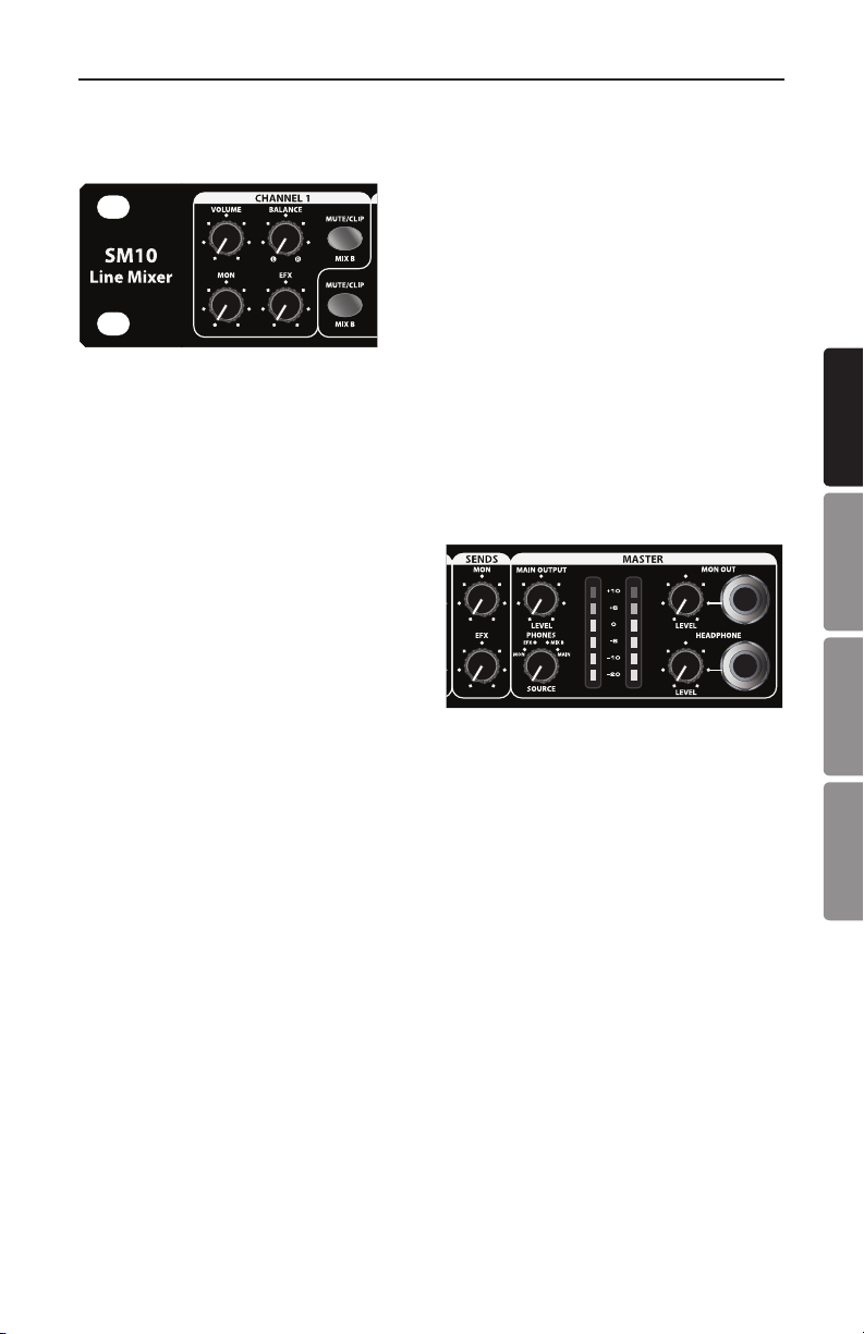
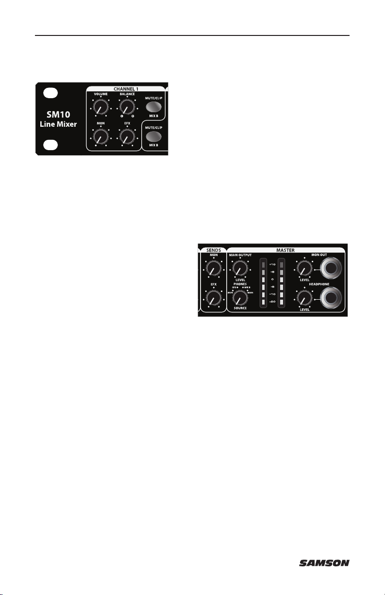
5. MUTE/CLIP/MIX B – This switch will flash RED when the channel
input signal peaks. To reduce distortion, turn the Volume
control counterclockwise until the clip indicator does not light
during normal use. When the switch is depressed the channel’s
signal path is interrupted to the main mix and the channel is
assigned to the MIX B bus.
6. LINE IN VOLUME – The SM10 features two additional stereo Line
Inputs (channels 9 and 10) which can be used to return the
outputs of the an external effects processor, or to connect the
output of any stereo line level device to the main mix.
7. MON Send – The MON signals (see #3) from input channels
1-8 are mixed together and sent to the MON Outputs. Use the
MON send control to set the amount of signal being sent to the
MON Output.
8. EFX SEND – The EFX signals (see #4) from input channels 1-8 are mixed
together and sent to the EFX Output. Use the EFX level controls to set the
amount of signal being sent to EFX Output.
7
8
8
Page 9
Controls and Functions
9
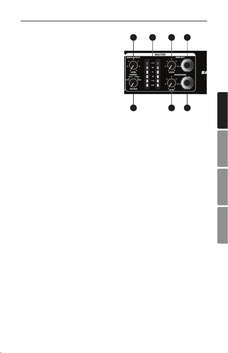
9. MAIN OUTPUT LEVEL – This knob
determines the final output signal level.
Signals from all channels are routed
here just before leaving the SM10 via
its left and right Main Output jacks. The
12 o’clock center detent position of the
control indicates unity gain (no level
attenuation or boost).
10. SOURCE Select Switch – The Source
select Switch allows you to configure the
Output Meter (see #11) and Headphone
output (see #15) to monitor the MON,
EFX, MIX B and Main Output buses.
11. Output Meter – This six-segment meter shows the continuous output level
of the Main Mix, MON, EFX, or MIX B, depending on the position of the
SOURCE select switch (see #10). For optimum signal-to-noise ratio,
adjust all levels so that program material is usually at or around 0 VU, with
occasional, but not steady, excursions to the red segments.
12. MON OUT LEVEL – The SM10 provides a second MON output connector
carrying a mono signal of the MON mix. The MON OUT LEVEL control knob is
used to set the volume of the MON OUT jack.
10
11
12
13
14 15
ENGLISH
FRANÇAISDEUTSCHEESPAÑOL
13. MON OUT Jack – The left and right MON mix are summed together to a
monaural signal and sent out this connector. The signal at the MON OUT jack
follows the MON OUT LEVEL (see #12) control knob.
14. HEADPHONE LEVEL – This knob sets the level of the signal sent to the
HEADPHONE jack. To avoid possible damage to connected headphones,
always turn this all the way off (to the fully counterclockwise position) before
plugging in a pair of headphones—then raise the level slowly while listening.
15. HEADPHONE Jack – Connect standard stereo headphones to this jack (via a
1/4” TRS plug) for monitoring of the MON, EFX, MIX B and Main Output
buses, depending on the position of the SOURCE select switch (see #10).
SM10 9
Page 10
Input and Output Connections
6
7
8
9
10
18
6
7
8
9
11
12
13
10
14 15
18
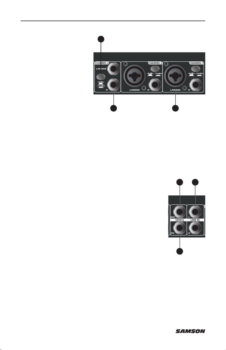
16. Mic/Line Inputs (channels 1
and 2) - Use these Combo
XLR plus 1/4” jacks to
connect a microphone
or line level signal to
channels 1 and 2. The
XLR inputs provide
48-volt phantom power
for use with condenser
microphones.
17. Line Inputs - Use these balanced 1/4” jacks to connect line level sources such
as synthesizers, drum machines, MP3 players, or effects processors to any of
the 8 channels. When connecting monophonic (as opposed to stereo) signal
sources, use the left inputs; the Balance control for that channel will then act
as a constant level pan control.
18. Input Level Switch – Use this switch to independently set the sensitivity of
channels 1-8 line level inputs. When the switch is in the up position the
input are set to +4dBu. When the switch is depressed the input is set to
-10dBv.
19. Stereo LINE IN (channels 9-10) – Two stereo 1/4” jacks for
connecting stereo line level sources like those from the
outputs of effects processors. These inputs can also be
used to link multiple SM10’s or to add the output from
another mixer to the SM10 without taking up channel line
inputs.
20. MON Output – The signals present at the MON stereo 1/4”
output are sent from the MON send, which are fed from
the input channels’ MON control knobs. In a live sound
situation this can be used to create a monitor mix by
connecting the MON output to a power amp and monitor
speaker.
1617
19
20
21
21. EFX Output – The stereo 1/4” EFX Output is used to send a
signal to an external signal processor such as a delay or reverb. The signal
present at the EFX Output is sent from the EFX bus, which is fed from the
input channel’s EFX control knob.
10
Page 11
Input and Output Connections
19
20
21
3
4
5
19
20
21
2223
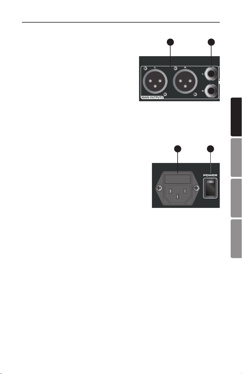
22. MAIN OUTPUTS 1/4” Jacks - In live
performance applications, these outputs
can be used to connect the SM10 to a
power amp and speakers. In recording
applications, these outputs are used
to connect to a stereo device such as
computer sound card, MP3, or hard disk
recorder. The signals at the Main Outputs
jacks follow the Main Output level controls.
23. MAIN OUTPUTS XLR Jacks - In live performance applications, these male XLR
outputs can be used to connect the SM10 to a power amp and speakers.
In recording applications, these outputs can be used to connect to a stereo
device such as computer sound card, MP3, or hard disk recorder. The signal
at the Main Outputs jacks follow the Main Output level control.
24. Power Switch – Use this switch to turn the
SM10 on and off. To avoid potential damage to
your speakers, turn the SM10 on before you turn
on any connected power amps—and turn it off
after the power amps are turned off. The switch
should be in the off position when connecting
the SM10 to the mains.
25. AC Inlet – Connect the supplied IEC cable here.
2223
2425
ENGLISH
FRANÇAISDEUTSCHEESPAÑOL
SM10 11
Page 12

SM10 Quick Start
The following section explains the basic operation of the SM10.
CONNECTING MICROPHONES AND INSTRUMENTS
1. Remove all packing materials (save them in case of need for future service)
and decide where the unit is to be physically placed—it can be mounted in
any standard 19” rack (requiring one rack space), or used on a tabletop.
2. Before connecting mics or instruments, make sure that the power to all your
systems components, including the SM10, are turned off. Also, make sure that
the Main Output control knob is turned all the way down.
3. Connect the cable(s) to your microphone(s) and instrument(s), and insert the
other end of the cable(s) firmly into the appropriate input(s) on the SM10.
NOTE: SETTING THE INPUT GAIN – When connecting a microphone to channels 1
and 2, it’s a good idea to start with the Volume control turned all the way down.
Slowly raise the Volume control until you see the CLIP LED turn on. Now, back
the Volume control down so that the MUTE/CLIP LED only lights for a short time
during the loudest input the channel will experience.
4. Switch on the power of any peripheral devices, and then power up the SM10.
NOTE: It is important to remember the Golden Rule of audio … “LAST ON, FIRST
OFF”. Translated, this means that when turning on your system, you should
always turn your power amplifiers or powered monitors on LAST, and when turning
your system off, turn your power amps off FIRST. This helps avoid any loud pops
caused by rush current at power up, which can sometimes damage loudspeakers.
5. Turn on your power amp or powered monitors and raise the level control to the
manufacturers’ recommended operating level.
6. Set the Main Output control of the SM10 master section to the 12 o’clock
(unity) position.
7. While speaking into the mic (or playing the instrument), adjust the channel
Volume control so that the “0” LED of the MAIN section peak level meter
lights only occasionally.
12
Page 13
SM10 Quick Start
SENDING AN INDEPENDENT MIX TO THE MONITOR SPEAKERS
The SM10’s MON auxiliary send can be
used to feed a separate set of amplifiers and
loudspeakers for stage monitors. This lets
you build one stereo mix for the main mix, or
amplifiers and speakers facing the audience,
and another stereo mix for the amplifiers and
monitor speakers facing the musicians.
1. Raise the MON controls for the channels that you wish to hear from the
monitor speakers.
NOTE: MON controls are “pre-fader sends,” which means they are not affected by
the Volume control level settings of each channel. This allows you to create a mix
for the monitors that is independent of the main left and right mix.
2. Raise the MON SEND control to
adjust the level of the mixed signal
from the channel MON controls until
the desired level is reached at the
rear panel MON Output jack.
3. For added monitoring flexibility, the
front panel MON Output (mono) can
be connected to a powered monitor
speaker. Slowly raise the MON Level
control until the desired level is
reached.
4. The MON mix can be monitored via headphones, by setting the PHONES
SOURCE switch to MON.
NOTE: Listening to high volume levels through headphones for even a short time
may damage your hearing and/or your headphones. Always turn the HEADPHONE
LEVEL control all the way counterclockwise before connecting your headphones.
Slowly raise the HEADPHONE LEVEL until a comfortable listening level is
reached. Noise over 85 dB can cause gradual hearing loss. Learn to establish a
safe listening level.
ENGLISH
FRANÇAISDEUTSCHEESPAÑOL
SM10 13
Page 14
SM10 Quick Start
USING AN EXTERNAL EFFECT
If you prefer to use an external device for
effects processing, you can easily connect
the unit using the SM10 EFX bus. Follow
the simple steps below to interface your
processor:
1. Connect the EFX OUTPUT to the input of the external effect processor.
2. Connect the outputs of the effects processor to channel 9 stereo line input.
3. Set the EFX SEND control to the 12 o’clock position.
4. Raise the EFX knobs for the channels to which you want the external effect to
be applied.
5. Set the input level of the external
effect so that the sound is not
distorted and so that the effect’s input
meter does not indicate a clipped
signal.
6. Use the channel 9 Volume control
to adjust the level of the effects
processed by the external effects
device.
7. The EFX bus can be monitored via headphones, by setting the PHONES
SOURCE switch to EFX.
NOTE: Listening to high volume levels through headphones for even a short time
may damage your hearing and/or your headphones. Always turn the HEADPHONE
LEVEL control all the way counterclockwise before connecting your headphones.
Slowly raise the HEADPHONE LEVEL until a comfortable listening level is
reached. Noise over 85 dB can cause gradual hearing loss. Learn to establish a
safe listening level.
14
Page 15
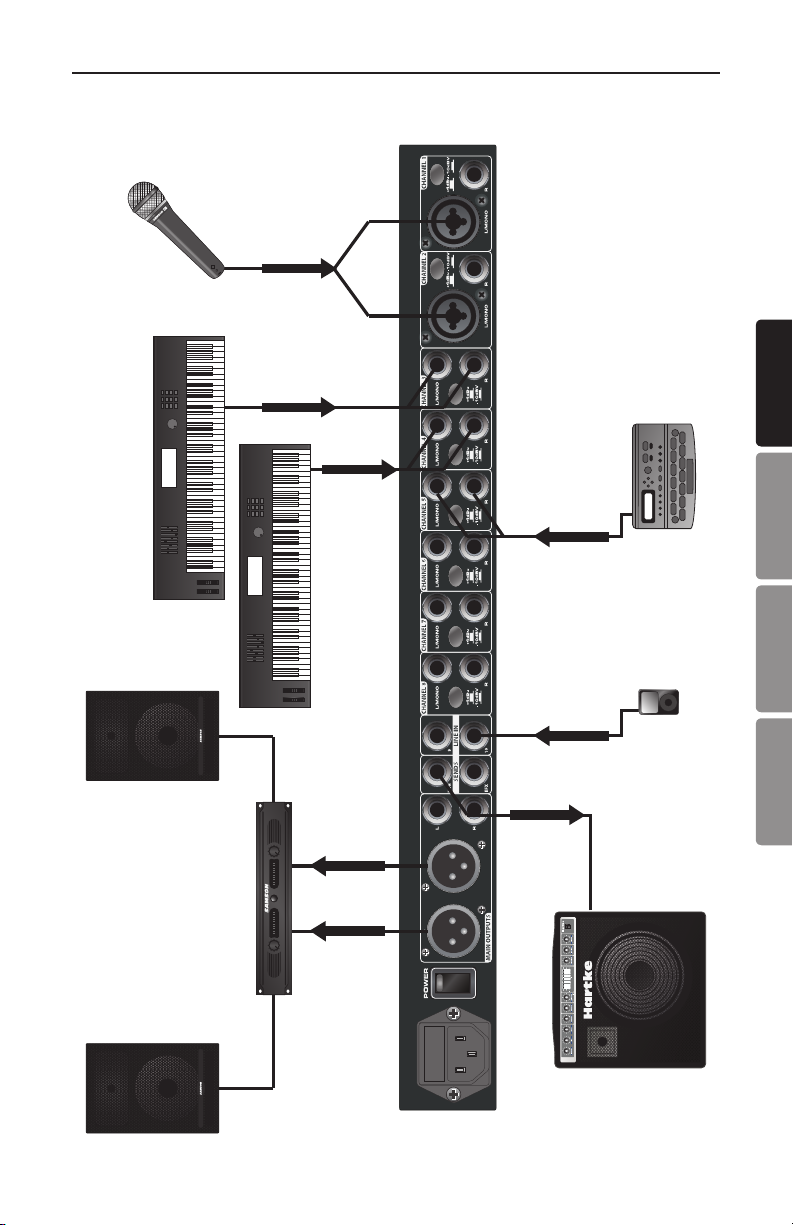
SM10 System Setup
SIGNAL FLOW
SIGNAL FLOW
ENGLISH
SIGNAL FLOW
SIGNAL FLOW
FRANÇAISDEUTSCHEESPAÑOL
SIGNAL FLOW
SIGNAL FLOW
SIGNAL FLOW
SIGNAL FLOW
SM10 15
Page 16

Specifications
Inputs
Microphone XLR balanced (2)
Line 1/4” TRS balanced (Ch 1-8),
1/4” stereo (Ch 9-10)
Input Impedance
Mic 1.5K Ohms
Line 23K Ohms (+4 dBu, Ch 1-8)
40K Ohms (-10 dBV, Ch 1-8)
20K Ohms (Ch 9-10)
Maximum Gain
Mic 65 dB
Line 39 dB
Line Operating Level +4 dBu / -10 dBV selectable
Maximum Input Level (1 kHz, ±3 dB)
Mic Input -4 dBu
Line Input +28 dBu
Equivalent Input Noise - 123 dBu unweighted
Outputs
Main Outputs
Type 1/4” TRS balanced (2), XLR (2)
Output Impedance 200 Ohms Main Out
Gain Range -∞ to +15 dB
Max output level +22 dBu
MON (Pre Fade Out) 1/4” impedance balanced mono output
(front panel), Stereo MON (rear panel)
EFX (Post Fade Out) 1/4” unbalanced
Output Impedance 100 Ohms
Headphone 1/4” TRS Stereo
Output (600 Ohm load) 100 mW
System
Frequency Response 10 Hz – 23 kHz ±1 dB
Signal-to-noise ratio > 90 dB typical
THD <0.01% typical
Crosstalk (1 kHz) -70 dB between input channels
-70 dB between input/output channels
Phantom Power 48 Volts DC
Power Requirements 100-120/120-240 VAC ~ 50-60Hz 50W
Dimensions 19” L x 8.25” W x 1.75” H
484mm L x 210mm W x 44.5mm H
Weight 6 lbs / 2.8 kg
16
Page 17
Consignes de sécurité importantes
ATTENTION
RISQUE D’ÉLECTROCUTION —
NE PAS OUVRIR
ATTENTION : POUR RÉDUIRE LES RISQUES D’ÉLECTROCUTION, VEILLEZ À NE PAS
OUVRIR LE BOÎTIER. CONFIEZ LES RÉPARATIONS UNIQUEMENT À UN TECHNICIEN
QUALIFIÉ.
Le symbole de l’éclair prévient l’utilisateur de la présence de tensions “dangereuses” et non isolées dans l’appareil, d’une amplitude suffisante pour présenter
un risque d’électrocution.
Le symbole du point d’exclamation prévient l’utilisateur de la présence d’instructions importantes sur le fonctionnement et la maintenance de ce produit dans le
mode d’emploi fourni.
ENGLISH
Pour mettre ce produit au rebut, ne le mélangez pas aux ordures ménagères. Il existe
un système de collecte séparée pour les produits électroniques usagés, conformément
à la législation qui prévoit le traitement, la récupération et le recyclage corrects.
Les ménages dans les 28 états membres de l'UE, en Suisse et en Norvège peuvent
mettre au rebut leurs produits électroniques usagés gratuitement auprès d'installations de
collecte agréées ou auprès d'un détaillant (si vous achetez un produit neuf similaire).
Pour les pays non mentionnés ci-dessus, veuillez contacter les autorités locales pour connaitre
la méthode de traitement appropriée.
Ce faisant, vous vous assurerez que votre produit subit le traitement, la récupération et le
recyclage nécessaires et prévenez ainsi les effets négatifs potentiels sur l'environnement et
la santé humaine.
FRANÇAISDEUTSCHEESPAÑOL
SM10 17
Page 18

Informations Importantes sur votre sécurité
1. Veuillez lire toutes les instructions.
2. Conservez ces instructions.
3. Respectez les mises en garde.
4. Suivez les instructions.
5. L’appareil ne doit pas être exposé
aux projections liquides. Ne placez
aucun objet contenant un liquide sur
l’appareil (vase, verre, etc.).
6. Nettoyez avec un tissu sec.
7. Veillez à ne pas obstruer les fentes de
ventilation. Installez l’appareil selon les
instructions du fabricant.
8. N’installez pas près d’une source de
chaleur (radiateurs, etc.), ou de tout
équipement générant de la chaleur
(amplificateurs de puissance).
9. Utilisez uniquement les fixations et
accessoires spécifiés par le fabricant.
10. Déconnectez l’appareil du secteur en
présence d’orage ou lors de périodes
d’inutilisation prolongées.
11. Ne retirez pas la terre du cordon
secteur ou de la prise murale. Les
fiches canadiennes avec polarisation
(avec une lame plus large) ne doivent
pas être modifiées. Si votre prise
murale ne correspond pas au modèle
fourni, consultez votre électricien.
12. Protégez le cordon secteur contre tous
les dommages possibles (pincement,
tension, torsion, etc.). Veillez à ce
que le cordon secteur soit libre, en
particulier à sa sortie du boîtier.
13. Utilisez uniquement le support, le pied,
ou la table spécifiés par le fabricant,
ou vendus avec l’appareil. Lorsque
vous utilisez un chariot, procédez avec
vigilance lorsque vous vous déplacez
pour éviter toute
blessure aux personnes
et tout dommage aux
équipements.
14. Consultez un service de réparation
qualifié pour tout dysfonctionnement
(dommage sur le cordon secteur, baisse
de performances, exposition à la pluie,
projection liquide dans l’appareil,
introduction d’un objet dans le boîtier,
etc.).
15. INTERRUPTEUR MARCHE/ARRÊT :
les produits équipés d’un interrupteur
marche/arrêt ne garantissent pas une
isolation totale entre l’appareil et le
secteur.
16. ISOLATION DU SECTEUR : La fiche
secteur doit rester accessible à tout
moment. Dans le cas d’une installation
en Rack ou d’une installation ne
permettant pas l’accès à la fiche
secteur, un interrupteur multipolaire
avec ouverture/fermeture par contacts
(espacés d’au moins 3 mm) sur chaque
élément de l’alimentation secteur
(toutes les phases, neutre et terre) doit
être incorporé au câblage du Rack ou
du bâtiment.
17. APPAREILS ÉQUIPÉS D’UN FUSIBLE
ACCESSIBLE PAR L’EXTÉRIEUR :
Remplacez le fusible uniquement par
un autre exactement identique.
18. ÉQUIPEMENTS MULTI-TENSION:
Selon le pays d’utilisation, cet appareil
nécessite un cordon secteur avec des
fiches adaptées au format local et aux
normes locales. Connectez cet appareil
uniquement à une source secteur
correspondant à la description située
en face arrière. Pour réduire les risques
d’incendie et d’électrocution, confiez
toutes les réparations à un personnel
qualifié.
18
Page 19

Introduction
Le mélangeur en Rack Samson SM10 est un outil extrêmement polyvalent et
très pratique pour de très nombreuses applications audio. Le SM10 vous offre
huit entrées ligne stéréo indépendantes, et deux voies avec entrées XLR pour
micros. Vous disposez également de deux entrées ligne supplémentaires en Jacks
6,35 mm stéréo et de réglage de niveau permettant la connexion de plusieurs
mélangeurs SM10. Le SM10 vous offre une multitude d’options de routage des
signaux, avec fonctions de retour/écoute Monitor (pré-Fader), EFX (post-Fader),
et départs de Mix B sur les voies 1-8. La section des généraux du SM10 offre des
options d’écoute complètes. La sortie casque et les afficheurs de niveaux peuvent
être configurés pour indiquer le niveau des sorties MON out, EFX out, Mix B, ou
Main. Vous disposez également d’une sortie supplémentaire MON Out avec réglage de niveau pour vous permettre d’accéder au départ MON Send directement
depuis la face avant. Logé dans un boîtier Rack 19 pouces d’une seule unité en
hauteur et alimentation interne, le SM10 s’intègre à tous les types d’installation.
Il offre une fiabilité totale pour vos concerts.
Dans ces pages, vous trouverez une description détaillée des fonctions du mélangeur en Rack SM10, une présentation des réglages, les instructions d’installation et d’utilisation, ainsi que les caractéristiques techniques. Vous trouverez
également une carte de garantie — prenez le temps de la remplir et de nous la
renvoyer pour pouvoir bénéficier de nos services d’assistance et recevoir les informations sur les autres produits Samson.
Avec un entretien adapté et une ventilation suffisante, votre SM10 vous donnera
satisfaction pendant de très nombreuses années. Prenez le temps de noter le
numéro de série et la date d’achat pour toute référence ultérieure.
ENGLISH
FRANÇAISDEUTSCHEESPAÑOL
Numéro de série : ____________________________________________
Date d’achat : __________________________________________
Pour faire réparer votre mélangeur, vous devez tout d’abord obtenir un numéro
d’autorisation de retour auprès de nos services. Sans ce numéro, nous ne pouvons
pas accepter le produit. Appelez Samson au 1-800-3SAMSON (1-800-372-6766)
pour obtenir ce numéro avant de nous expédier le produit. Conservez les emballages d’origine pour tout retour en atelier. Si vous avez acheté le produit hors des
États-Unis, contactez votre revendeur Samson pour obtenir les informations sur la
garantie.
SM10 19
Page 20

Tour d’horizon
Le mélangeur en Rack Samson SM10 répond à tous vos besoins en
installation fixe, en sonorisation, en gestion des retours de scène,
comme pré-mélangeur pour claviers, et pour toutes vos applications
d’enregistrement. Voici un tour d’horizon de ses fonctions :
• Dix entrées ligne stéréo (deux configurables micro/ligne
• Préamplificateurs micro à faible bruit avec alimentation fantôme
48 Volts.
• Routage du signal polyvalent grâce aux bus de sorties Main Mix,
Mix B, Mon, EFX, et à la sortie mono.
• Réglage de Balance sur chaque voie stéréo.
• Deux départs Aux permettant de diriger les signaux vers les effets
externes, ou de créer un mixage séparé pour les retours de scène.
• Sorties casque et mono de face avant avec réglages de niveau
• Sortie casque et afficheurs à Leds indiquant le niveau des bus
MON, EFX, MIX B et MAIN MIX
• Sélecteur de niveau d’entrée ligne +4 dBu ou -10 dBV.
• Sorties lignes symétriques stéréo générales en XLR et en Jacks
6,35 mm.
• Cran central sur tous les réglages d’entrée, facilitant l’utilisation
en situations d’éclairage faible (sur scène, par exemple).
• Boîtier métal au format Rack 1 unité en hauteur avec
alimentation interne, pour une intégration optimale à tout
système existant.
• Produit robuste et de haute qualité vous garantissant une
utilisation fiable, concert après concert, session d’enregistrement
après session d’enregistrement.
20
Page 21

Réglages et fonctions
21
1. VOLUME – Ce bouton contrôle le volume de
la voie dans les sorties générales Main Out.
La position crantée centrale vous donne le
niveau sans accentuation ou atténuation du
niveau d’entrée.
À partir de cette position, tournez le bouton
vers la droite pour accentuer le niveau.
Tournez le bouton vers la gauche pour
l’atténuer.
Pour obtenir le meilleur rapport signal/
bruit possible, tous les réglages de volume
doivent être proches de la position crantée
centrale. Sur les voies qui ne sont pas utilisées, réglez le volume au minimum.
2. BALANCE – Lorsque les deux entrées d’une voie sont connectées, le signal
d’entrée gauche est automatiquement placé complètement à gauche et le
signal d’entrée droit est automatiquement placé complètement à droite. Dans
ce cas, le bouton de Balance contrôle le niveau relatif des signaux des deux
entrées. Lorsque le bouton est placé au centre, les deux signaux sont de même
niveau. Lorsque vous déplacez le bouton vers la gauche, le signal de droite
reste identique, et le signal de gauche est atténué. Lorsque vous déplacez le
bouton vers la droite, le signal de gauche reste identique, et le signal de droite
est atténué.
Lorsque seule l’entrée gauche est connectée, le bouton sert de panoramique
à niveau constant, vous permettant de placer le signal d’entrée mono dans le
champ stéréo de sortie.
3. MON (Monitor) Send – Le bouton de départ MON vous permet de régler le
niveau du signal de la voie dirigé vers les sorties MON. Le réglage de départ
MON est pré-Fader et le signal n’est pas affecté par la position du réglage
de volume de la voie. Ce réglage est en général utilisé pour créer un mixage
séparé pour les retours de scène. Lorsque le bouton MON est sur sa position
centrale crantée, le niveau du signal est identique au niveau du signal
d’entrée.
4. EFX (Effects) Send – Le départ EFX vous permet de régler le niveau du signal
de la voie dans les sorties EFX. Le réglage de départ EFX est post-Fader et le
signal est affecté par la position du volume de la voie. Ces départs sont en
général utilisés pour diriger le signal de la voie vers un processeur d’effets
externe. Lorsque le bouton EFX est sur sa position centrale crantée, le niveau
du signal est identique au niveau du signal d’entrée.
4
3
5
ENGLISH
FRANÇAISDEUTSCHEESPAÑOL
SM10 21
Page 22

9
11
12
13
10
14 15
Réglages et fonctions
5. MUTE/CLIP/MIX B – La touche clignote en ROUGE lorsque le signal d’entrée de
la voie écrête. Pour réduire la distorsion, tournez le bouton de volume vers la
gauche de sorte que le témoin ne s’allume pas en utilisation normale. Lorsque
la touche est enfoncée, le signal de la voie est retiré du mixage des sorties
générales et il est affecté au MIX B.
6. LINE IN VOLUME – Le SM10 vous offre deux entrées stéréo ligne
supplémentaires (voies 9 et 10) qui peuvent être utilisées pour
recevoir le signal de sortie d’un processeur d’effets externe, ou
pour connecter la sortie d’un équipent stéréo à niveau ligne au
mixage général.
7. MON Send – Les signaux MON (voir n° 3) des voies 1-8 sont
mélangés et transmis aux sorties MON. Utilisez le bouton MON
pour déterminer le niveau de la sortie MON.
8. EFX SEND – Les signaux EFX (voir n° 4) des voies 1-8 sont
mélangés et transmis aux sorties EFX. Utilisez le bouton EFX
pour déterminer le niveau de la sortie EFX.
7
6
8
22
Page 23

Réglages et fonctions
9. MAIN OUTPUT LEVEL – Ce bouton
détermine le niveau des sorties
générales Main Left et Right du SM10.
Lorsque le bouton est sur sa position
centrale crantée, le niveau du signal est
identique au niveau du signal d’entrée.
10. Sélecteur SOURCE – Ce sélecteur
détermine le niveau indiqué par
l’afficheur de niveau (voir n° 11) et le
signal de la sortie casque (voir n° 15)
pour l’écoute des signaux MON, EFX,
MIX B et des sorties générales Main.
11. Afficheur de niveau – Cet afficheur de niveau à six segments indique le niveau
des sorties Main Mix, MON, EFX, ou MIX B, selon la position du sélecteur
SOURCE (voir n° 10). Pour optimiser le rapport signal/bruit en sortie, réglez
tous les niveaux de sorte que le niveau soit autour de 0 VU, avec quelques
passages exceptionnels dans le rouge.
12. MON OUT LEVEL – Le SM10 vous offre une sortie MON portant un signal mono
du mixage MON. Le bouton MON OUT LEVEL contrôle le niveau de sortie du
Jack MON OUT.
13. MON OUT Jack – Les signaux gauche et droit du mixage MON sont mélangés
en mono et transmis à cette sortie. Le signal de la sortie MON OUT suit le
niveau du bouton MON OUT LEVEL (voir n° 12) .
14. HEADPHONE LEVEL – Ce bouton détermine le niveau de la sortie casque du
Jack HEADPHONE. Pour éviter tout dommage au casque connecté, réglez
le bouton au minimum avant de connecter un casque. Montez ensuite
progressivement le niveau.
15. HEADPHONE Jack – Connectez un casque stéréo standard à ce Jack stéréo
6,35 mm pour l’écoute des bus MON, EFX, MIX B et Main, selon la position
du sélecteur SOURCE (voir n° 10).
9
10
11
12
13
14 15
ENGLISH
FRANÇAISDEUTSCHEESPAÑOL
SM10 23
Page 24

Connexions d’entrées/sorties
6
7
8
9
11
12
13
10
14 15
6
7
8
9
10
18
18
16. Entrées Mic/Line (voies 1
et 2) - Utilisez ces deux
entrées combinées XLR/
Jack 6,35 mm pour
connecter un signal à
niveau micro ou ligne aux
voies 1 et 2. La XLR porte
l’alimentation fantôme 48
Volts pour vos micros à
condensateur.
1617
17. Line Inputs - Utilisez ces Jacks 6,35 mm symétriques pour connecter vos
signaux source à niveau ligne comme vos synthétiseurs, boîtes à rythme,
lecteurs de MP3, ou vos processeurs d’effets à l’une des 8 voies de mixage.
Si vous utilisez un signal mono, connectez-le à l’entrée gauche (Left) de la
voie ; le réglage de Balance sert alors de panoramique.
18. Touche Input Level – Utilisez cette touche pour régler la sensibilité d’entrée
ligne des voies 1-8. En position haute, la valeur est de +4 dBu. En position
basse, la valeur est de -10 dBv.
19. Entrées stéréo LINE IN (voies 9-10) – Deux Jacks stéréo 6,35
mm pour la connexion de sources ligne stéréo comme
les sorties de processeurs d’effets externes. Ces entrées
peuvent servir à coupler plusieurs SM10 ou pour relier
la sortie d’un autre mélangeur au SM10 sans utiliser les
autres voies ligne.
20. MON Output – Les signaux de la sortie en Jack stéréo 6,35
mm MON sont transmis par le bouton MON Send, et en
provenance des boutons de voies MON. Sur scène, cette
sortie vous permet de créer un mixage séparé pour les
retours de scène, en connectant la sortie MON à un ampli
de puissance et à des retours de scène.
20
21
19
21. EFX Output – La sortie en Jack stéréo 6,35 mm EFX transmet le signal au
processeur d’effets externe comme un délai ou une réverbération. Le signal
de la sortie EFX est celui transmis par le bouton EFX de chaque voie.
24
Page 25

Connexions d’entrées/sorties
19
20
21
3
4
5
19
20
2223
22. Sorties Jacks 6,35 mm MAIN OUTPUTS-
Pour les applications de scène, utilisez
ces sorties pour connecter le SM10 à un
ampli de puissance avec enceintes ou à
des enceintes actives. En enregistrement,
connectez ces sorties à l’enregistreur, à
l’ordinateur, à la carte son, à l’enregistreur
de MP3, etc. Le niveau des signaux de
la Main Outputs dépend du bouton Main
Output.
23. MAIN OUTPUTS XLR Jacks - Pour les applications de scène, utilisez ces sorties
pour connecter le SM10 à un ampli de puissance avec enceintes ou à des
enceintes actives. En enregistrement, connectez ces sorties à l’enregistreur,
à l’ordinateur, à la carte son, à l’enregistreur de MP3, etc. Le niveau des
signaux de la Main Outputs dépend du bouton Main Output.
24. Interrupteur POWER – Place le SM10 sous/
hors tension. Pour éviter tout dommage aux
enceintes, placez le SM10 sous tension avant
les amplificateurs de puissance — et placezle hors tension après les amplis de puissance.
Le SM10 doit être hors tension lorsque vous le
reliez au secteur.
25. Embase secteur – Connectez le cordon secteur
fourni à cette embase.
2223
2425
ENGLISH
FRANÇAISDEUTSCHEESPAÑOL
SM10 25
Page 26

SM10 — Prise en main
Les chapitres qui suivent vous expliquent comment utiliser le SM10.
CONNEXION DES MICROS ET INSTRUMENTS
1. Retirez les éléments de l’emballage et conservez-le (en cas de réparation ou
autre). Décidez où vous souhaitez installer le mélangeur — dans un Rack 19
pouces (une unité en hauteur) ou à plat.
2. Avant de connecter vos micros ou instruments, veillez à ce que tous les
équipements audio soient hors tension, dont le SM10. Veillez également à ce
que le bouton Main Output soit réglé au minimum.
3. Connectez les câbles des micros et des instruments aux entrées du SM10.
REMARQUE : RÉGLAGE DU GAIN D’ENTRÉE – Lorsque vous connectez un micro aux
voies 1 et 2, commencez par régler le volume de la voie au minimum. Montez
progressivement le bouton de volume jusqu’à ce que la Led CLIP s’allume.
Descendez le volume de sorte que la Led MUTE/CLIP ne s’allume que sur les
passages les plus forts.
4. Placez les équipements audio périphériques sous tension, puis le SM10.
REMARQUE : Souvenez-vous de la règle la plus importante en audio… “LE
DERNIER SOUS TENSION, LE PREMIER HORS TENSION”. Cela signifie que
vous devez toujours placer vos amplis de puissance ou enceintes actives sous
tension en DERNIER, et lorsque vous avez terminé, devez toujours placer vos
amplis de puissance ou enceintes actives hors tension en PREMIER. Ceci évite
tout bruit de transitoire violent causé par l’appel en courant qui peuvent parfois
détruire les enceintes.
5. Placez votre amplificateur de puissance et/ou vos enceintes actives sous
tension et montez le niveau selon les recommandations du fabricant.
6. Réglez le bouton Main Output du SM10 en position centrale.
7. Tout en parlant dans le micro (ou tout en jouant), réglez le volume de la voie
correspondante, de sorte que la Led “0” de la section de sortie MAIN ne
s’allume qu’occasionnellement.
26
Page 27

SM10 — Prise en main
CRÉATION D’UN MIXAGE INDÉPENDANT POUR LES RETOURS DE SCÈNE
Le départ auxiliaire MON du SM10 peut être
utilisé pour alimenter des amplis et enceintes
séparés placés sur scène en retour. Ceci vous
permet de créer un mixage stéréo pour le
mixage principal Main (pour la façade ou pour
vos amplificateurs), et un autre mixage stéréo
pour les amplis et les retours de scène du
musicien.
1. Montez le bouton MON des voies que vous souhaitez entendre dans les
retours.
REMARQUE : Les boutons MON sont des départs “pré-Fader”, ce qui signifie qu’ils
ne sont pas affectés par le bouton de volume de la voie. Ceci vous permet de créer
un mixage de retours totalement indépendant des sorties générales Left et Right.
2. Montez le bouton MON SEND pour
régler le niveau général du mixage des
boutons de voies MON, transmis par le
Jack de face arrière MON Output.
3. Pour plus de possibilités d’écoute,
la sortie MON Output (mono) de
la face avant peut être connectée
à une enceinte active. Montez
progressivement le niveau MON Level.
4. Vous pouvez écouter le mixage MON au casque, en réglant la source d’écoute
PHONES SOURCE sur MON.
REMARQUE : L’écoute au casque à niveau élevé pendant un moment même court
peut endommager votre audition et/ou votre casque. Baissez toujours le niveau
HEADPHONE LEVEL au minimum avant de connecter votre casque. Montez
progressivement le niveau HEADPHONE LEVEL jusqu’à obtenir un niveau
d’écoute confortable. L’écoute au delà de 85 dB peut causer une perte progressive
de l’audition. Soyez raisonnable et responsable dans vos réglages.
ENGLISH
FRANÇAISDEUTSCHEESPAÑOL
SM10 27
Page 28

SM10 — Prise en main
UTILISATION D’UN EFFET EXTERNE
Si vous préférez utiliser un effet externe pour
le traitement de vos effets, vous pouvez aisément connecter le processeur externe au bus
EFX du SM10. Suivez les étapes ci-dessous
pour connecter votre processeur externe :
1. Connectez la sortie EFX OUTPUT à l’entrée du processeur d’effets.
2. Connectez les sorties du processeur d’effets à l’entrée ligne stéréo de la voie
9.
3. Réglez le bouton EFX SEND en position centrale.
4. Montez les boutons EFX des voies sur lesquelles vous souhaitez ajouter de
l’effet.
5. Réglez le niveau d’entrée du pro-
cesseur externe en veillant à ne pas
saturer le son (l’afficheur de niveau
d’entrée de l’effet ne doit pas indiquer
d’écrêtage).
6. Utilisez le bouton de volume de la
voie 9 pour régler le niveau général du
processeur d’effets externe.
7. Vous pouvez écouter le mixage EFX au casque, en réglant la source d’écoute
PHONES SOURCE sur EFX.
REMARQUE : L’écoute au casque à niveau élevé pendant un moment même court
peut endommager votre audition et/ou votre casque. Baissez toujours le niveau
HEADPHONE LEVEL au minimum avant de connecter votre casque. Montez progressivement le niveau HEADPHONE LEVEL jusqu’à obtenir un niveau d’écoute
confortable. L’écoute au delà de 85 dB peut causer une perte progressive de
l’audition. Soyez raisonnable et responsable dans vos réglages.
28
Page 29

SM10 — Exemple de configuration
SIGNAL FLOW
SIGNAL FLOW
ENGLISH
SIGNAL FLOW
SIGNAL FLOW
FRANÇAISDEUTSCHEESPAÑOL
SIGNAL FLOW
SIGNAL FLOW
SIGNAL FLOW
SIGNAL FLOW
SM10 29
Page 30

Caractéristiques techniques
Entrées
Micro XLR symétriques (2)
Line
Impédance d’entrée
Mic 1,5 kOhms
Line 23 kOhms (+4 dBu, voies 1-8)
40 kOhms (-10 dBV, voies 1-8)
20 kOhms (voies 9-10)
Gain maximum
Mic 65 dB
Line 39 dB
Niveau ligne +4 dBu / -10 dBV, commutable
Niveau maximum d’entrée (1 kHz, ±3 dB)
Entrée Mic -4 dBu
Entrée Line +28 dBu
Bruit équivalent rapporté en entrée - 123 dBu, mesure non pondérée
Sorties
Sorties Main
Type
Impédance de sortie 200 Ohms (sorties Main)
Plage de gain -∞ à +15 dB
Niveau max. de sortie +22 dBu
MON (sortie Pré-Fader)
EFX (sortie Post-Fader)
Impédance de sortie 100 Ohms
Sortie casque
Puissance (charge de 600 Ohms) 100 mW
Jack symétrique stéréo 6,35 mm (voies 1-8),
Jack symétrique stéréo 6,35 mm (voies 9-10)
Jacks symétriques stéréo
Jack symétrique
MON (face arrière)
Jack asymétrique 6,35 mm
Jack stéréo 6,35 mm
(2), XLR (2)
mono (face avant), stéréo
Système
Réponse en fréquence 10 Hz – 23 kHz, ±1 dB
Rapport Signal/bruit > 90 dB type
Distorsion harmonique <0,01 % type
Diaphonie (1 kHz) -70 dB entre voies d’entrée
-70 dB entre entrées/sorties voies
Alimentation fantôme 48 Volts cc
Tension secteur 100-120/120-240 Vca ~ 50-60Hz 50W
Dimensions 484 mm/19 pouces (l) x 210 mm (p)
x 44,5 mm (h)
Poids 2,8 kg
30
Page 31

Wichtige Sicherheitshinweise
RISQUE DE CHOC ÉLECTRONIQUE -
AVIS
NE PAS OUVRIR
VORSICHT: UM DIE GEFAHR EINES STROMSCHLAGS ZU VERRINGERN, ENTFERNEN
SIE NICHT DIE VORDER- ODER RÜCKSEITE DES GERÄTS. IM INNERN BEFINDEN SICH
KEINE VOM ANWENDER WARTBAREN BAUTEILE. ÜBERLASSEN SIE DIE WARTUNG
QUALIFIZIERTEM FACHPERSONAL.
Der Blitz mit Pfeilspitze im gleichseitigen Dreieck soll den Anwender vor nichtisolierter “gefährlicher Spannung” im Geräteinnern warnen. Diese Spannung
kann so hoch sein, dass die Gefahr eines Stromschlags besteht.
Das Ausrufezeichen im gleichseitigen Dreieck soll den Anwender auf wichtige
Bedienungs- und Wartungsanleitungen aufmerksam machen, die im mitgelieferten Informationsmaterial näher beschrieben werden.
Entsorgen Sie dieses Gerät nach Ende seiner Nutzungsdauer bitte nicht als Restmüll.
Nutzen Sie bitte die in Ihrer Region bestehenden Entsorgungsmöglichkeiten (Sammelsystem) für Elektronikprodukte. Mit einer fachgerechten Entsorgung ermöglichen
Sie ordnungsgemäße Handhabung, Aufbereitung und Wiederverwendung gemäß den
gesetzlichen Bestimmungen.
Privathaushalte in den 28Mitgliedsstaaten der EU, in der Schweiz und in Norwegen können
gebrauchte elektronische Geräte kostenlos in den dafür vorgesehenen Sammelstellen oder
beim Einzelhändler (bei Kauf eines ähnlichen Neugeräts) abgeben.
In allen anderen als den genannten Ländern wenden Sie sich zwecks ordnungsgemäßer Entsorgung bitte an die für Ihren Ort zuständige Behörde.
So gehen Sie sicher, dass das von Ihnen entsorgte Produkt ordnungsgemäß gehandhabt,
aufgearbeitet oder recycelt wird, und leisten einen wichtigen Beitrag zum Schutz von Umwelt
und Gesundheit.
ENGLISH
FRANÇAISDEUTSCHEESPAÑOL
SM10 31
Page 32

Wichtige Sicherheitshinweise
1. Lesen Sie diese Anleitungen.
2. Bewahren Sie diese Anleitungen auf.
3. Beachten Sie alle Warnungen.
4. Befolgen Sie alle Anweisungen.
5. Setzen Sie dieses Gerät keinen tropf enden
oder spritzenden Flüssigkei ten aus und
stellen Sie keine mit Flüs sigkeit gefüllten
Objekte, z. B. Vasen, auf das Gerät.
6. Reinigen Sie das Gerät nur mit einem trock-
enen Tuch.
7. Blockieren Sie keine Belüftungsöffnungen.
Installieren Sie das Gerät nur entsprechend
den Anweisungen des Herstellers.
8. Installieren Sie das Gerät nicht in der
Nähe von Wärmequellen, wie Heizkörpern,
Wärmeklappen, Öfen oder anderen Geräten
(inklusive Verstär ker).
9. Benutzen Sie nur die vom Hersteller angege-
benen Halterungen/Zubehörteile.
10. Ziehen Sie den Netzstecker des Geräts bei
Gewittern oder längeren Betriebspausen aus
der Steckdose.
11. Setzen Sie die Schutzfunktion des polarisi-
erten oder geerdeten Steckers nicht außer
Kraft. Ein polarisierter Stecker hat zwei
flache, unterschied lich breite Pole. Ein geerdeter Stecker hat zwei flache Pole und einen
drit ten Erdungs stift. Der breitere Pol oder der
dritte Stift dient Ihrer Sicher heit. Wenn der
vorhandene Steck er nicht in Ihre Steckdose
passt, las sen Sie die ver altete Steckdose von
einem Elektriker ersetzen.
12. Schützen Sie das Netzkabel dahin gehend,
dass niemand darüber laufen und es nicht
geknickt werden kann. Achten Sie hier bei
speziell auf Netz stecker, Mehr fachsteck dosen
und den Kabel anschluss am Gerät.
13. Benutzen Sie das Gerät nur mit den Wagen,
Ständern, Stativen, Halterungen oder
Tischen, die vom Hersteller
empfohlen oder mit dem Gerät
ver kauft wurden. Gehen Sie beim
Bewe gen eines Wagens vorsichtig
vor, damit die Wagen/GeräteKombina t ion nicht umkippt und
Verletzungen verursacht.
14. Überlassen Sie die Wartung qualifiziertem
Fachpersonal. Eine Wartung ist notwendig, wenn das Gerät auf irgendeine Weise
beschädigt wurde, z. B. am Netzkabel oder
-stecker, oder wenn Flüssigkeiten/Objekte in
das Gerät gelangt sind, es Regen/Feuchtigkeit ausgesetzt war, nicht mehr wie gewohnt
funktioniert oder fallen gelassen wurde.
15. NETZSCHALTER: Ein evt. vor han dener
Netzschalter unterbricht die Verbindung zum
Stromnetz NICHT.
16. TRENNUNG VOM STROMNETZ: Der Netzstecker sollte immer problemlos erreichbar
sein. Ist der Netzstecker nicht erreichbar, z.
B. Rackmontage oder andere Installationen,
muss ein allpoliger Netzschalter mit einer
Kontakttrennung von mindestens 3 mm in
jedem Pol in die elektrische Installation des
Racks oder Gebäudes eingebaut werden.
17. GERÄTE MIT EXTERN ZUGÄNGLICHER
SICHERUNG: Verwenden Sie als Er satz nur
Sicherungen gleichen Typs und Nenn werts.
18. VERSCHIEDENE NETZSPANNUNGEN:
Abhängig von der bei der Installation verfügbaren Stromquelle, müssen Netzkabel und/
oder Anschluss ste cker des Geräts eventuell
ausgetau scht werden. Schließen Sie das
Gerät nur an die Spannungsquellen an, die
auf der Geräterückseite angegeben sind. Um
die Gefahr eines Brandes oder Stromschlags
zu verringern, überlassen Sie die Wartung
qualifiziertem Fachpersonal.
32
Page 33

Einleitung
Der Samson SM10 Rack-Mischer eignet sich als vielseitiges Werkzeug für die
verschiedensten Beschallungsaufgaben. Der SM10 Mischer ist ausgestattet
mit acht unabhängigen Stereo Line-Eingangskanälen sowie zwei Kanälen mit
XLR-Mikrofonvorverstärkern. Zusätzlich sind zwei Line-Eingänge mit 1/4”
Stereobuchsen und Pegelreglern verfügbar, über die man mehrere SM10
Mischer verketten kann. Der SM10 zeichnet sich aus durch eine Vielzahl von
Signalrouting-Optionen, z. B. Monitor (pre-fade), EFX (post-fade) und Mix
B Sends auf den Kanälen 1 - 8. Die Master-Sektion des SM10 verfügt über
erweiterte Abhörmöglichkeiten. Kopfhörerausgang und Anzeigen können zu
Monitorzwecken wahlweise auf MON Out, EFX Out, Mix B oder Main Out
geschaltet werden. Weiterhin bietet der SM10 Mischer einen separaten MONAusgang mit Pegelregler, den man schnell auf MON Send schalten kann, ohne
Änderungen an der Geräterückseite vornehmen zu müssen. Der SM10 ist inklusive
Netzteil in einem 19” 1HE Rackgehäuse untergebracht und eignet sich aufgrund
seiner Zuverlässigkeit und Robustheit sowohl für Installationen als auch für den
rauen Touralltag.
Auf diesen Seiten finden Sie eine detaillierte Beschreibung der Funktionen
Ihres SM10 Rack-Mischers und dessen Bedienfeld sowie Anleitungen zur Ein richtung und Anwendung plus ausführliche technische Daten. Die beiliegende
Garantiekarte sollten Sie unbedingt ausfüllen und ab schicken, damit Sie online
technische Unterstützung in Anspruch neh men kön nen und zukünftig aktualisierte
Informationen über dieses und andere Samson-Pro dukte erhal ten. Besuchen Sie
bitte auch unsere Website (www.samsontech.com), auf der Sie Informationen über
unsere gesamte Produktlinie finden.
Bei sorgsamer Behandlung und angemessener Belüftung wird Ihr SM10
viele Jahre störungsfrei arbeiten. Die Seriennummer Ihres Geräts sollten Sie
sicherheitshalber in der Zeile unten eintragen.
ENGLISH
FRANÇAISDEUTSCHEESPAÑOL
Seriennummer: ____________________________________________
Kaufdatum: __________________________________________
Sollte Ihr Gerät einmal gewartet werden müssen, besorgen Sie sich vor der
Rücksendung an Samson bitte eine Return Authorization Number (RA). Ohne
diese Rück sende berechtigungsnummer wird das Gerät nicht angenommen. Bitte
rufen Sie Samson unter der Nummer 1-800-3SAMSON (1-800 -372-6766) an,
um eine RA-Nummer vor der Rücksendung zu erhalten. Heben Sie das Original ver pack ungs material auf und schicken Sie das Gerät möglichst im originalen
Karton und Verpack ungsmaterial zu rück. Wenn Sie das Samson Produkt außerhalb
der USA gekauft haben, setzen Sie sich bei Fragen zu Garantie und Wartung bitte
mit Ihrem lokalen Vertrieb in Verbindung.
SM10 33
Page 34

Features
Der Samson SM10 Rack-Mischer ist eine eigenständige
Komplett lösung für Festinstallationen, Live-Beschallungen,
Bühnenmonitorsysteme, Keyboard-Submischer und
Aufnahmeanwendungen. Seine wichtigsten Features sind:
• 10 Eingangskanäle – zwei Mic/Line plus zehn Stereo Line
• Rauscharme, separate Mikrofonvorverstärker mit 48-Volt
Phantomspannung
• Vielseitiges Signalrouting via Main Mix-, Mix B-, Mon-, EFX BusAusgänge sowie Mono-Ausgang
• Balance-Regler pro Kanal zum Überblenden der relativen Pegel
von Stereoeingängen
• Zwei Aux Sends für das Signalrouting zu externen Effekten oder
zum Erstellen von separaten Mischungen für Bühnenmonitore
• Vorderseitige Kopfhörer- und Mono-Ausgänge mit separaten
Pegelreglern
• Flexible Quellenwahl für Kopfhörer und 6-Segment LED-Anzeige
zum Überwachen von MON, EFX, MIX B und MAIN MIX
• Line Input Level-Schalter für Eingangssignale mit Line-Pegeln
von +4 dBu oder -10 dBV
• Elektronisch symmetrische Stereo XLR und 1/4” Line-Hauptausgänge
• Einrastende Mittestellung bei allen Eingangsreglern als
Orientierunghilfe bei schwacher Beleuchtung, z. B. LivePerformance
• 19” 1HE Rack-Metallgehäuse mit internem Netzteil, mühelos in
vorhandene Systeme integrierbar
• Hochwertige und robuste Konstruktion für einen zuverlässigen
Betrieb an jedem Veranstaltungsort und bei jeder Session
34
Page 35

Regler und Funktionen
21
1. VOLUME – Dieser Regler steuert den Pegel
der Kanaleingänge. Mit ihm können Sie die
Lautstärke der verschiedenen Signale, die
an den Hauptausgängen gemischt werden,
stufenlos einstellen. Die einrastende 12
Uhr-Position des Reglers zeigt Unity Gain
(Eingangspegel = Ausgangspegel) an.
Bei einer Linksdrehung des Reglers aus der
12 Uhr-Position wird das Signal be dämpft.
Bei einer Rechtsdrehung des Reglers
aus der 12 Uhr-Position wird das Signal
verstärkt.
Um den bestmöglichen Geräuschspannungsabstand zu erzielen, sollten die
VOLUME-Regler aller signalführenden Kanäle generell auf oder in der Nähe der
12-Uhr-Position stehen. Die Pegelregler unbenutzter Kanäle sollten ganz nach
links auf Minimalpegel zurückgedreht werden.
2. BALANCE – Wenn beide Eingänge eines Kanals belegt sind, wird das linke
Eingangssignal automatisch im Panorama ganz nach links und das rechte
Eingangssignal ganz nach rechts gelegt. In diesem Fall steuert der BalanceDrehregler die relativen Pegel des Eingangssignalpaars. Steht der Regler auf
der einrastenden Mitteposition, sind die Signale gleich stark. Bei einer Reglerdrehung aus der Mitte nach links bleibt die Stärke des linken Eingangssignals
unverändert, aber das rechte Eingangssignal wird bedämpft. Bei einer Reglerdrehung aus der Mitte nach rechts bleibt die Stärke des rechten Eingangssignals unverändert, aber das linke Eingangssignal wird bedämpft.
Wenn nur der linke Eingang belegt ist, fungiert der Balance-Regler als PanRegler mit konstantem Pegel, mit dem Sie das Eingangssignal stufenlos überall im Links/Rechts-Stereofeld platzieren können.
3. MON (Monitor) Send – Mit dem MON Send-Regler können Sie das Signal zu
den MON-Ausgängen leiten. Da MON Send pre-fader angeordnet ist, wird das
Signal von der Stellung des Volume-Reglers des Kanals nicht verändert. Mit
diesen Sends erstellt man normalerweise eine separate Mischung für das Monitorsystem. Wenn der MON Send-Regler auf der rastenden 12 Uhr-Mitteposition
steht, wird das Signal mit Unity Gain weitergeleitet.
4
3
5
ENGLISH
FRANÇAISDEUTSCHEESPAÑOL
SM10 35
Page 36

9
11
12
13
10
14 15
Regler und Funktionen
4. EFX (Effects) Send – Mit dem EFX Send-Regler können Sie das Signal zu den
EFX-Ausgängen leiten. Da EFX Send post-fader geschaltet ist, richtet sich
der Signalpegel nach der Stellung des Volume-Reglers des Kanals. Mit diesen
Sends werden Signale normalerweise zu externen Effektgeräten geleitet. Wenn
der EFX Send-Regler auf der rastenden 12 Uhr-Mitteposition steht, wird das
Signal mit Unity Gain weitergeleitet.
5. MUTE/CLIP/MIX B – Dieser Schalter blinkt ROT, wenn das Eingangssignal
des Kanals übersteuert. Um Verzerrungen zu verringern, drehen Sie den
Volume-Regler nach links, bis die Clip-Anzeige im normalen Betrieb nicht
mehr leuchtet. Bei gedrückter Taste wird der Signalweg des Kanals zur
Hauptmischung unterbrochen und dem MIX B Bus zugewiesen.
6. LINE IN VOLUME – Der SM10 verfügt über zwei zusätzliche
Stereo Line-Eingänge (Kanäle 9 und 10), über die man die
Ausgangssignale eines externen Prozessors in den Mischer
zurückführen oder die Ausgangssignale eines Stereogeräts mit
Line-Pegel in die Hauptmischung einspeisen kann.
7. MON Send – Die MON-Signale (siehe 3) der Eingangskanäle 1
- 8 werden gemischt und zu den MON-Ausgängen geleitet. Mit
dem MON Send-Regler bestimmen Sie den Signalanteil, der zu
den MON-Ausgängen geleitet wird.
8. EFX SEND – Die EFX-Signale (siehe 4) der Eingangskanäle 1 - 8
werden gemischt und zum EFX-Ausgang geleitet. Mit den EFX
Send-Reglern bestimmen Sie den Signalanteil, der zum EFXAusgang geleitet wird.
7
6
8
36
Page 37

Regler und Funktionen
9. MAIN OUTPUT LEVEL – Die-
ser Regler bestimmt den
endgültigen Ausgangssignalpegel. Hierher werden die Signale aller Kanäle geleitet, bevor
sie den SM10 über die linken
und rechten Main OutputBuchsen verlassen. Wenn der
Regler auf der rastenden 12
Uhr-Mitteposition steht, wird
das Signal mit Unity Gain (ohne
Bedämpfung/Verstärkung)
weitergeleitet.
10. SOURCE-Wahlschalter – Mit dem Source-Wahlschalter bestimmen Sie, welcher
Bus (MON, EFX, MIX B oder Main Output) via Ausgangsanzeige (siehe 11)
und Kopfhörerausgang (siehe 15) überwacht wird.
11. Ausgangspegelanzeige – Diese 6-Segment Anzeige zeigt – abhängig von
der Stellung des SOURCE-Wahlschalters (siehe 10) – kontinuierlich den
Ausgangspegel des Main Mix-, MON-, EFX- oder MIX B-Bus an. Für den
optimalen Geräuschspannungsabstand sollten Sie alle Pegel so einstellen,
dass das Programmmaterial normalerweise auf oder in der Nähe von 0 VU
liegt – mit gelegentlichen, aber nicht ständigen Ausschlägen in den roten
Segmentbereich.
12. MON OUT LEVEL – Der SM10 verfügt über einen zweiten MON-Ausgang,
an dem ein Monosignal der MON-Mischung anliegt. Mit dem MON OUTPegelregler stellen Sie den Pegel an der MON OUT-Buchse ein.
13. MON OUT-Buchse – Die linken und rechten MON-Mischungen werden zu einem
Monosignal summiert und über diese Buchse ausgegeben. Das an der MON
OUT-Buchse anliegende Signal wird vom MON OUT-Pegelregler (siehe 12)
gesteuert.
14. HEADPHONE LEVEL – Dieser Regler steuert den Pegel des zur HEADPHONE-
Buchse geleiteten Signals. Drehen Sie den Regler immer ganz zurück (ganz
nach links), bevor Sie Kopfhörer anschließen, um diese und Ihr Gehör nicht
zu beschädigen. Drehen Sie den Regler dann langsam bis zur gewünschten
Lautstärke auf.
15. HEADPHONE-Buchse – An diese Buchse schließen Sie standard
Stereokopfhörer (via 1/4” TRS-Stecker) an, um je nach Stellung des
SOURCE-Wahlschalters (siehe 10) einen der MON-, EFX-, MIX B- und Main
Output-Busse abzuhören.
9
10
11
12
13
14 15
ENGLISH
FRANÇAISDEUTSCHEESPAÑOL
SM10 37
Page 38

Eingänge und Ausgänge
6
7
8
9
11
12
13
10
14 15
6
7
8
9
10
18
18
16. Mic/Line-Eingänge (Kanäle 1
und 2) - Über diese XLR &
1/4” Kombibuchsen können
Sie ein Mikrofon- oder LinePegel-Signal an die Kanäle
1 und 2 anschließen.
Die XLR-Eingänge liefern
48-Volt Phantomspannung
für den Betrieb von
Kondensatormikrofonen.
1617
17. Line-Eingänge - Über diese symmetrischen 1/4” Buchsen schließen Sie
Line-Pegel-Quellen, wie Synthesizer, Drum Machines, MP3 Player oder
Effektprozessoren an die 8 Kanäle an. Monosignale (im Gegensatz zu
Stereosignalen) werden an die linken Eingänge angeschlossen. In diesem Fall
fungiert der Balance-Regler dieses Kanals als Pan-Regler mit konstantem
Pegel.
18. Eingangspegelschalter – Mit dieser Taste können Sie die Empfindlickeit der
Line-Pegel-Eingänge der Kanäle 1 - 8 getrennt einstellen. Bei gelöster Taste
ist der Eingang auf +4dBu gesetzt. Bei gedrückter Taste ist der Eingang auf
-10dBv gesetzt.
19. Stereo LINE IN (Kanäle 9-10) – Zwei 1/4” Stereobuchsen
für den Anschluss von Line-Pegel-Stereoquellen, z. B.
Ausgänge eines Effektprozessors. Über diese Eingänge kann
man auch mehrere SM10 koppeln oder die Ausgangssignale
eines anderen Mischers in den SM10 ein speisen, ohne die
Line-Eingänge der Kanäle zu belegen.
20. MON-Ausgang – Die am 1/4” MON-Stereoausgang
anliegenden Signale kommen vom MON Send, der wiederum von den MON-Reglern der Eingangskanäle gespeist
wird. Bei Live-Beschallungen kann man mit dem MONAusgang eine Monitormischung erstellen, indem man ihn an
eine Endstufe plus Monitorbox anschließt.
20
21
19
21. EFX-Ausgang – Über den 1/4” EFX-Stereoausgang kann man ein Signal zu
einem externen Signalprozessor, z. B. Delay oder Reverb, leiten. Das am
EFX-Ausgang anliegende Signal kommt vom EFX Bus, der wiederum von den
EFX-Reglern der Eingangskanäle gespeist wird.
38
Page 39

Eingänge und Ausgänge
19
20
21
3
4
5
19
20
21
2223
22. MAIN OUTPUTS 1/4” Buchsen - Bei der
Live-Beschallung kann man den SM10
über diese Ausgänge mit einer Endstufe
und Boxen verbinden. Bei Aufnahmen
kann man diese Ausgänge mit einem
Stereogerät, z. B. Computer-Soundkarte,
MP3- oder Harddisk-Recorder, verbinden.
Die an den Main Output-Buchsen anliegenden Signale werden mit dem Main
Output-Pegelregler gesteuert.
23. MAIN OUTPUTS XLR-Buchsen - Bei der Live-Beschallung kann man den
SM10 über diese XLR-Stecker mit einer Endstufe und Boxen verbinden.
Bei Aufnahmen kann man diese Ausgänge mit einem Stereogerät, z. B.
Computer-Soundkarte, MP3- oder Harddisk-Recorder, verbinden. Die an den
Main Output-Buchsen anliegenden Signale werden mit dem Main OutputPegelregler gesteuert.
24. Power-Schalter – Mit diesem Schalter wird der
SM10 ein- und ausgeschaltet. Um die Boxen
nicht zu beschädigen, sollten Sie den SM10
vor den Endstufen einschalten und nach den
Endstufen ausschalten. Der Schalter sollte auf
Off stehen, wenn Sie den SM10 ans Stromnetz
anschließen.
25. Netzeingang – Schließen Sie hier das
mitgelieferte IEC-Kabel an.
2223
ENGLISH
2425
FRANÇAISDEUTSCHEESPAÑOL
SM10 39
Page 40

SM10 Schnellstart
Der folgende Abschnitt beschreibt den elementaren Betrieb des SM10.
MIKROFONE UND INSTRUMENTE ANSCHLIESSEN
1. Entfernen Sie das gesamte Verpackungsmaterial (bewahren Sie es für
zukünftige Wartungsarbeiten auf) und entscheiden Sie, wo das Gerät
aufgestellt werden soll — es kann in ein standard 19” Rack (1HE) installiert
oder auf einem Tisch platziert werden.
2. Bevor Sie Mikrofone oder Instrumente anschließen, müssen alle
Systemkomponenten, inklusive SM10, ausgeschaltet sein. Stellen Sie
ebenfalls sicher, dass der Main Output-Regler ganz zurückgedreht ist.
3. Verbinden Sie die Kabel mit Ihren Mikrofonen und Instrumenten und stecken
Sie die anderen Kabelenden fest in die geeigneten Eingänge des SM10.
HINWEIS: EINGANGSVERSTÄRKUNG EINSTELLEN – Wenn Sie ein Mikrofon an die
Kanäle 1 und 2 anschließen, sollten Sie den Volume-Regler zunächst ganz
zurückdrehen. Drehen Sie den Volume-Regler dann langsam auf, bis die CLIP
LED aufleuchtet. Drehen Sie anschließend den Volume-Regler so weit zurück,
dass die MUTE/CLIP LED nur bei den lautesten Eingangspegeln des Kanals kurz
aufleuchtet.
4. Schalten Sie die Peripheriegeräte und danach den SM10 ein.
HINWEIS: Vergessen Sie nie die goldene Audioregel “ZULETZT EIN, ZUERST
AUS”. Dies bedeutet, dass Sie beim Einschalten des Systems die Endstufen
oder Aktivboxen immer ZULETZT einschalten sollten und beim Ausschalten
des Systems die Endstufen ZUERST ausschalten sollten. So können Sie laute
Popp-Geräusche vermeiden, die beim Ein-/Ausschalten durch Spannungsspitzen
verursacht werden und manchmal Boxen beschädigen können.
5. Schalten Sie Ihre Endstufe oder Aktivmonitore ein und stellen Sie den
Pegelregler auf den vom Hersteller empfohlenen Betriebspegel ein.
6. Stellen Sie den Main Output-Regler der SM10 Master-Sektion auf 12 Uhr
(Unity Gain) ein.
7. Sprechen Sie ins Mikro fon (oder spielen Sie Ihr Instrument) und
stellen Sie den Volume-Regler des Kanals so ein, dass die “0” LED der
Spitzenpegelanzeige in der MAIN-Sektion nur gelegentlich leuchtet.
40
Page 41

SM10 Schnellstart
UNABHÄNGIGE MISCHUNG ZU DEN MONITORBOXEN LEITEN
Über die MON Aux Sends des SM10 kann
man ein separates Set von Verstärkern und
Boxen als Bühnenmonitore betreiben. So
kann man eine Stereomischung für die
Haupt-PA, also die aufs Publikum gerichteten
Verstärker und Boxen, aufbauen und eine
andere Stereomischung für die auf die
Musiker gerichteten Verstärker und Boxen.
1. Drehen Sie die MON-Regler der Kanäle auf, die über die Monitorboxen
erklingen sollen.
HINWEIS: Da die MON-Regler “pre-fader send” angeordnet sind und nicht von
den Pegeleinstellungen der Volume-Regler jedes Kanals beeinflusst werden,
kann man für die Monitore eine Misch ung erstellen, die von der linken/rechten
Hauptmischung unabhängig ist.
2. Drehen Sie den MON SEND-Regler
auf, um die Lautstärke des von den
MON-Reglern der Kanäle kommenden
gemischten Signals so einzustellen,
dass der gewünschte Pegel an der
rückseitigen MON-Ausgangsbuchse
anliegt.
3. Für noch mehr Monitoring-Flexibilität können Sie den vorderseitigen MON-
Ausgang (Mono) mit einem Aktivmonitor verbinden. Drehen Sie den MONPegelregler langsam auf, bis der gewünschte Pegel erreicht ist.
4. Indem Sie den PHONES SOURCE-Schalter auf MON einstellen, können Sie
die MON-Mischung in den Kopfhörern überwachen.
HINWEIS: Hohe Lautstärkepegel in den Kopfhörern können bereits nach kurzer Zeit zu Schäden des Gehörs und/oder Kopfhörers führen. Drehen Sie den
HEADPHONE LEVEL-Regler immer ganz nach links, bevor Sie Ihren Kopfhörer
anschließen. Drehen Sie dann den HEADPHONE LEVEL-Regler langsam auf,
bis ein angenehmer Abhörpegel erreicht ist. Geräusche über 85 dB können zu
allmählichem Gehörverlust führen. Beschränken Sie sich auf einen sicheren
Abhörpegel.
ENGLISH
FRANÇAISDEUTSCHEESPAÑOL
SM10 41
Page 42

SM10 Schnellstart
EXTERNEN EFFEKT EINSETZEN
Wenn Sie für die Effektbearbeitung ein
externes Gerät verwenden möchten, können
Sie dieses problemlos über den EFX-Bus des
SM10 anschließen. Gehen Sie schrittweise
wie folgt vor, um Ihren Prozessor ins System
zu integrieren:
1. Verbinden Sie den EFX-AUSGANG mit dem Eingang des externen Effekt-
prozessors.
2. Verbinden Sie die Ausgänge des Effektprozessors mit den Stereo Line-Eingän-
gen von Kanal 9.
3. Stellen Sie den EFX SEND-Regler auf 12 Uhr ein.
4. Drehen Sie die EFX-Regler der Kanäle auf, auf die der externe Effekt ange-
wandt werden soll.
5. Stellen Sie den Eingangspegel des
externen Effekts so ein, dass der Klang
nicht verzerrt und die Ein gangs anzeige
des Effekts kein übersteuertes Signal
anzeigt.
6. Stellen Sie mit dem Volume-Regler
von Kanal 9 den Pegel der Signale
ein, die mit dem externen Effektgerät
bearbeitet wurden.
7. Sie können den EFX Bus über Kopfhörer abhören, indem Sie den PHONES
SOURCE-Schalter auf EFX einstellen.
HINWEIS: Hohe Lautstärkepegel in den Kopfhörern können bereits nach kur zer
Zeit zu Schäden des Gehörs und/oder Kopfhörers führen. Drehen Sie den HEADPHONE LEVEL-Regler immer ganz nach links, bevor Sie Ihren Kopfhörer anschließen. Drehen Sie dann den HEADPHONE LEVEL-Regler langsam auf, bis ein
angenehmer Abhörpegel erreicht ist. Geräusche über 85 dB können zu allmählichem Gehörverlust führen. Beschränken Sie sich auf einen sicheren Abhörpegel.
42
Page 43

SM10 Systemeinrichtung
SIGNAL FLOW
SIGNAL FLOW
ENGLISH
SIGNAL FLOW
SIGNAL FLOW
FRANÇAISDEUTSCHEESPAÑOL
SIGNAL FLOW
SIGNAL FLOW
SIGNAL FLOW
SIGNAL FLOW
SM10 43
Page 44

Technische Daten
Eingänge
Mikrofon XLR symmetrisch (2)
Line 1/4” TRS symmetrisch (Kanäle 1-8),
1/4” stereo (Kanäle 9-10)
Eingangsimpedanz
Mic 1,5K Ohm
Line 23K Ohm (+4 dBu, Kanäle 1-8)
40K Ohm (-10 dBV, Kanäle 1-8)
20K Ohm (Kanäle 9-10)
Max. Gain
Mic 65 dB
Line 39 dB
Line-Betriebspegel +4 dBu / -10 dBV wählbar
Max. Eingangspegel (1 kHz, ±3 dB)
Mic-Eingang -4 dBu
Line-Eingang +28 dBu
Äquivalentes Eingangsrauschen - 123 dBu unbewertet
Ausgänge
Hauptausgänge
Typ 1/4” TRS symmetrisch (2), XLR (2)
Ausgangsimpedanz 200 Ohm Hauptausgang
Gain-Bereich -∞ bis +15 dB
Max. Ausgangspegel +22 dBu
MON (pre-fade Out) 1/4” impedanzsymmetrierter Monoausgang
(Front), Stereo MON (Rückseite)
EFX (post-fade Out) 1/4” asymmetrisch
Ausgangsimpedanz 100 Ohm
Kopfhörer 1/4” TRS Stereo
Ausgang (600 Ohm Last) 100 mW
System
Frequenzgang 10 Hz – 23 kHz ±1 dB
Geräuschspannungsabstand > 90 dB typisch
Klirrfaktor <0,01% typisch
Übersprechen (1 kHz) -70 dB zwischen Eingangskanälen
-70 dB zwischen Ein-/Ausgangskanälen
Phantomspannung 48 Volt DC
Betriebsspannung 100-120/120-240 VAC ~ 50-60Hz 50W
Abmessungen 484mm L x 210mm B x 44,5mm H
19” L x 8,25” B x 1,75” H
Gewicht 2,8 kg / 6 lbs.
44
Page 45

Instrucciones importantes de seguridad
RISQUE DE CHOC ÉLECTRONIQUE -
AVIS
NE PAS OUVRIR
PARA REDUCIR EL RIESGO DE DESCARGA ELÉCTRICA, NUNCA QUITE LA TAPA NI EL
CHASIS. DENTRO DEL APARATO NO HAY PIEZAS SUSCEPTIBLES DE SER REPARADAS
POR EL USUARIO. DIRIJA CUALQUIER REPARACIÓN AL SERVICIO TÉCNICO OFICIAL
El símbolo del relámpago dentro del triángulo equilátero pretende advertir al
usuario de la presencia de “voltajes peligrosos” no aislados dentro de la carcasa
del producto, que pueden ser de la magnitud suficiente como para constituir un
riesgo de descarga eléctrica a las personas
El símbolo de exclamación dentro del triángulo equilátero quiere advertirle de la
existencia de importantes instrucciones de manejo y mantenimiento (reparaciones) en los documentos que se adjuntan con este aparato
Si desea desechar este producto, no lo mezcle con los residuos domésticos de tipo
general. Existe un sistema de recogida por separado para los productos electrónicos,
de conformidad con la legislación que requiere un tratamiento, recuperación y reciclaje adecuados.
Los domicilios particulares de los 28 estados miembro de la UE, y de Suiza y Noruega, pueden devolver sus productos electrónicos usados sin cargo alguno en instalaciones de recogida
designadas o a un vendedor (en caso de que usted comprara uno nuevo similar).
Para los Países no mencionados arriba, por favor, póngase en contacto con sus autoridades
locales para informarse sobre un método de eliminación correcto.
Haciéndolo así, tendrá la seguridad de que su producto desechado se somete al tratamiento,
recuperación y reciclaje necesarios y, de esta manera, evitará efectos potencialmente negativos en el entorno y la salud humana.
ENGLISH
FRANÇAISDEUTSCHEESPAÑOL
SM10 45
Page 46

Instrucciones importantes de seguridad
1. Lea todo este manual de instrucciones.
2. Conserve estas instrucciones.
3. Preste atención a todas las advertencias.
4. Siga todo lo indicado en estas
instrucciones.
5. Este aparato no debe quedar expuesto a
salpicaduras, ni debe colocar objetos que
contengan líquidos (como puede ser un
jarrón) sobre él.
6. Limpie este aparato solo con un trapo seco.
7. No bloquee ninguna de las aberturas de
ventilación. Instale este aparato de acuerdo a
las instrucciones del fabricante.
8. No instale este aparato cerca de fuentes
de calor como radiadores, hornos u otros
aparatos (incluyendo amplificadores) que
generen calor.
9. Utilice solo accesorios/complementos
especificados por el fabricante.
10. Desconecte este aparato de la corriente
durante las tormentas eléctricas o cuando
no lo vaya a usar durante un periodo de
tiempo largo.
11. No anule el sistema de seguridad que supone
un enchufe polarizado o uno con toma de
tierra. Un enchufe polarizado tiene dos bornes
de distinta anchura. Uno con toma de tierra
tiene dos bornes iguales y una tercera lámina
para la conexión a tierra. El borne ancho
o la lámina se incluyen para su seguridad.
Si el enchufe incluido con este aparato no
encaja en su salida de corriente, haga que un
electricista sustituya su salida anticuada.
12. Coloque el cable de corriente de forma que
no pueda quedar aplastado o retorcido,
con especial atención en los enchufes,
receptáculos y en el punto en el que salen
del aparato.
13. Utilice este aparato solo con un soporte,
trípode o bastidor especificado por el
fabricante o que se venda directamente
con el propio aparato.
con ruedas, ponga especial
atención al mover la
combinación aparato/
bastidor para evitar posibles
accidentes en caso de un
vuelco.
Si utiliza un bastidor
14. Consulte cualquier posible reparación con
15. INTERRUPTOR DE ENCENDIDO: Si este
16. DESCONEXION DE LA CORRIENTE
17. PARA LAS UNIDADES EQUIPADAS
18. VOLTAJE DE ENTRADA MULTIPLE: Este
el servicio técnico. Este aparato deberá ser
reparado si ha resultado dañado de cualquier
forma, como por ejemplo si se ha dañado el
cable de corriente, si se ha derramado algún
líquido o se ha introducido algún objeto dentro
del aparato, si ha quedado expuesto a la lluvia
o la humedad, si no funciona normalmente o
si ha caído al suelo.
aparato dispone de un interruptor de
encendido, dicho interruptor NO corta la
conexión de la corriente.
ELECTRICA: Coloque el enchufe de forma
que siempre pueda acceder a él. En caso de
una instalación en rack o encastrada, en la
que no sea fácil acceder al enchufe, coloque
en el circuito eléctrico del rack o de la sala
un interruptor de corriente multipolar con una
separación de contactos de al menos 3 mm en
cada polo.
CON UN RECEPTACULO DE FUSIBLE
ACCESIBLE DESDE EL EXTERIOR:
Sustituya el fusible únicamente por otro de
idénticas características.
aparato puede requerir el uso de un cable de
alimentación o enchufe diferente (o ambos),
dependiendo de la fuente de alimentación
disponible. Conecte este aparato únicamente a
una fuente de alimentación como la indicada
en el panel trasero de este aparato. Para
reducir el riesgo de incendios o descargas
eléctricas, consulte cualquier posible
reparación con el servicio técnico.
46
Page 47

Introducción
La mesa de mezclas de montaje en rack Samson SM10 es una herramienta muy
versátil para una amplia gama de aplicaciones sonoras. La SM10 dispone de
ocho canales de entrada de línea stereo independientes, e incluye dos canales
con previos de micro XLR. Hay además dos entradas de línea adicionales con
conectores stereo de 6,3 mm y controles de nivel que puede usar para conectar
en cadena entre sí varias mesas SM10. La SM10 le ofrece una amplia gama
de opciones de ruteo de señal, con envíos Monitor (pre-fader), EFX (post-fader)
y de Mezcla B en los canales 1-8. La sección Master de la SM10 dispone de
amplias posibilidades de monitorización. Puede conmutar la salida de auriculares
y los medidores para que monitoricen la salida MON, la EFX, Mix B o la salida
principal. También dispone de una salida MON extra con control nivel para una
conexión rápida al envío MON sin tener que acceder al panel trasero. Montada en
un chasis rack de 19 pulgadas de un solo espacio y con fuente de alimentación
interna, la SM10 es fiable para cualquier instalación fija y lo suficientemente
robusta como para cualquier gira.
En estas páginas encontrará una descripción detallada de las características
de la mesa de mezclas de montaje en rack SM10, así como una descripción de
su panel frontal y posterior, instrucciones paso-a-paso para su configuración y
manejo y una completa tabla de especificaciones técnicas. También encontrará
una tarjeta de garantía—no se olvide de cumplimentarla y devolvérnosla por
correo para que pueda recibir soporte técnico online y para que podamos enviarle
información actualizada acerca de este y otros productos Samson en el futuro.
Además, no deje de visitar nuestra página web (www.samsontech.com) donde
encontrará información actualizada de toda nuestra línea de productos.
ENGLISH
FRANÇAISDEUTSCHEESPAÑOL
Con unos cuidados mínimos y una correcta refrigeración, su SM10 funcionará
sin darle ningún problema durante años. Para cualquier referencia futura, le
recomendamos que apunte aquí abajo el número de serie.
Número de serie: ___________________________________________
Fecha de compra: __________________________________________
En el improbable caso de que este aparato deba ser reparado en algún momento,
deberá conseguir un número de Autorización de devolución (RA) antes de enviar
este aparato a Samson. Sin este número, ninguna unidad será aceptada. Póngase
en contacto con Samson en el teléfono 1-800-3SAMSON (1-800-372-6766) para
solicitar su número de Autorización de devolución antes de devolvernos su unidad.
Conserve el embalaje original y las protecciones y, si es posible, devuélvanos la
unidad en ellos. Si adquirió este producto Samson fuera de los Estados Unidos,
póngase en contacto con su distribuidor local para que le facilite los detalles acerca
de la garantía y reparaciones.
SM10 47
Page 48

Características
La mesa de mezclas de montaje en rack Samson SM10 es una
completa solución todo-en-uno para instalaciones fijas, sonido directo,
monitorización de escenario, submezclas de teclados y aplicaciones
de grabación. Aquí puede ver algunas de sus características
principales:
• 10 canales de entrada – Dos de micro línea más diez de línea
stereo.
• Previos de micro independientes de bajo nivel de ruidos y con
alimentación fantasma de 48 V.
• Un versátil sistema de ruteo de señal a través de salidas de
mezcla principal, mezcla B, monitorización y bus de efectos, así
como una salida mono.
• Controles de balance en cada canal, que le permiten mezclar los
niveles relativos de las entradas stereo.
• Puede usar dos envíos auxiliares para rutar señales a efectos
externos o para crear una mezcla independiente para los
monitores de escenario.
• Conector de auriculares y salida mono en el panel frontal con
controles de nivel independientes.
• Flexible sistema de control de fuente de señal para auriculares y
panel de medidores que le permite monitorizar las señales MON,
EFX, MIX B y MAIN MIX.
• Interruptor de nivel de entrada de línea para señales de entrada
con nivel +4 dBu o -10 dBV.
• Salida principal stereo con nivel de línea, en conectores XLR y
6,3 mm, electrónicamente balanceadas.
• Muesca central en todos los controles de entrada, para un manejo
sencillo en situaciones de bajo nivel de luz como en actuaciones
en directo.
• Chasis metálico de un único espacio en rack de 19” con fuente
de alimentación interna, que permite una integración fácil en
cualquier sistema existente.
• Construcción robusta y de calidad que le asegura un
funcionamiento fiable gira tras gira y sesión tras sesión.
48
Page 49

Controles y funciones
21
5
1. VOLUME – Este mando controla el volumen
de los canales de entrada y se usa para
ajustar de forma continua el volumen
percibido de las distintas señales que son
mezcladas en las salidas principales. Hay
una muesca en la posición de “las 12 en
punto” del mando que indica la ganancia
unitaria.
El giro del mando a la izquierda de la
muesca central hace que la señal sea
atenuada, mientras que el giro a la derecha
de la posición de “las 12 en punto” hace
que la señal sea realzada.
Para la mejor relación señal-ruido, debería dejar todos los controles de
volumen de los canales que lleven señal en su muesca central o cerca.
Los canales no usados deberían tener sus mandos de volumen en su tope
izquierdo; es decir, al mínimo nivel.
2. BALANCE – Cuando ambas entradas de un canal estén conectadas, la señal
izquierda será colocada automáticamente en el extremo izquierdo y la derecha
en el extremo derecho. En este caso, este mando controlará los niveles
relativos de la pareja de señales de entrada. Cuando este mando esté en su
muesca central, ambas señales tendrán la misma fuerza. Cuando lo gire hacia
la izquierda desde esa posición central, la señal de entrada izquierda tendrá
la misma fuerza pero la derecha será atenuada y a la inversa cuando gire el
mando a la derecha de su punto central.
Cuando solo conecte la entrada izquierda, este mando actuará como un control
Pan de nivel constante que le permitirá ubicar de forma continua la señal
entrante en cualquier punto del campo stereo izquierda-derecha.
3. Envío MON (monitor) – Este mando le permite rutar la señal a las salidas MON.
Este envío es pre-fader, por lo que la señal no se ve afectada por la posición
del control de volumen de canal. Estos envíos se suelen usar para crear una
mezcla independiente para un sistema de monitorización. Cuando este mando
esté en su posición central (con muesca), la señal será enviada a ganancia
unitaria.
4
3
ENGLISH
FRANÇAISDEUTSCHEESPAÑOL
SM10 49
Page 50

9
11
12
13
10
14 15
Controles y funciones
4. Envío EFX (efectos) – Este mando le permite rutar la señal a las salidas EFX.
Este envío es post-fader, con lo que el nivel de la señal es determinado por
la posición del control de volumen de canal. Estos envíos se suelen usar para
rutar señal a unidades de efectos externas. Cuando este mando esté en su
posición central (con muesca), la señal será enviada a ganancia unitaria.
5. MUTE/CLIP/MIX B – Este interruptor parpadeará en ROJO en los picos de
la señal del canal de entrada. Para reducir la distorsión, gire el control de
volumen a la izquierda hasta que el indicador no se ilumine durante un uso
normal. Cuando este interruptor esté pulsado, la ruta de señal del canal a la
mezcla principal quedará interrumpida (anulada) y el canal será asignado al
bus MIX B.
6. LINE IN VOLUME – El SM10 dispone de dos entradas de línea
stereo adicionales (canales 9 y 10) que puede usar para el
retorno de las salidas de una unidad de efectos externa o para
conectar la salida de cualquier dispositivo de nivel de línea
stereo a la mezcla principal.
7. Envío MON – Las señales MON (vea #3) de los canales de
entrada 1-8 son mezcladas y enviadas a las salidas MON. Use
este control para ajustar la cantidad de señal enviada a la
salida MON.
6
7
8. EFX SEND – Las señales EFX (vea #4) de los canales de entrada
1-8 son mezcladas y enviadas a las salidas EFX. Use este
control para ajustar la cantidad de señal enviada a la salida EFX.
50
8
Page 51

Controles y funciones
9. MAIN OUTPUT LEVEL – Este
mando determina el nivel
de señal de salida final. Las
señales de todos los canales
son rutadas aquí justo antes de
dejar el SM10 a través de sus
conectores de salida principal
izquierda y derecha. La posición
de muesca central indica la
ganancia unitaria (ni realce ni
atenuación de nivel).
10
9
11
12
13
14 15
10. Selector SOURCE – Este selector le permite configurar el medidor de salida
(vea #11) y la salida de auriculares (vea #15) para que monitoricen los buses
MON, EFX, MIX B y los de las salidas principales.
11. Medidor de salida – Este medidor de seis segmentos le muestra el nivel de
salida continuo de la mezcla principal, MON, EFX o MIX B, dependiendo de
la posición del selector SOURCE (vea #10). Para la mejor relación señalruido, ajuste todos los niveles de forma que el material de programa muestre
una medición de 0 VU o cerca, con algún momento puntual (no continuo) en
que se ilumine alguno de los segmentos rojos.
12. MON OUT LEVEL – El SM10 le ofrece un segundo conector de salida MON que
lleva una señal mono de la mezcla MON. Este mando MON OUT LEVEL se
usa para ajustar el volumen de la salida MON OUT.
13. Salida MON OUT – La mezcla MON izquierda y derecha es sumada a una señal
monoaural y enviada a este conector. La señal en este conector MON OUT es
controlada por el mando MON OUT LEVEL (vea #12).
14. HEADPHONE LEVEL – Este mando ajusta el nivel de la señal enviada a la toma
HEADPHONE. Para evitar posibles daños en los auriculares conectados,
coloque siempre al mínimo (tope izquierdo) este mando antes de conectar
unos auriculares—y vaya subiendo el nivel poco a poco mientras escucha la
señal.
15. Toma HEADPHONE – Conecte unos auriculares stereo standard en esta toma
(con una clavija TRS de 6,3 mm) para monitorizar los buses de salida MON,
EFX, MIX B o la señal de salida principal, dependiendo de la posición del
selector SOURCE (vea #10).
ENGLISH
FRANÇAISDEUTSCHEESPAÑOL
SM10 51
Page 52

Conexiones de entrada y salida
6
7
8
9
11
12
13
10
14 15
6
7
8
9
10
18
16. Entradas de micro/línea
(canales 1 y 2) - Use estas
tomas Combo XLR + 6,3
mm para la conexión de
una señal de nivel de micro
o de línea a los canales
1 y 2. Las tomas XLR
le ofrecen alimentación
fantasma de 48 voltios
para el uso de micrófonos
condensadores.
17. Entradas de línea - Use estas tomas de 6,3 mm balanceadas para conectar
fuentes de nivel de línea como sintetizadores, cajas de ritmo, reproductores
de MP3 o procesadores de efectos a cualquiera de los 8 canales. Cuando
conecte fuentes monofónicas (no stereo), use las entradas izquierdas; el
control Balance de ese canal actuará entonces como un control de panorama
de nivel constante.
18. Interruptor de nivel de entrada – Uselo para ajustar de forma independiente la
sensibilidad de las entradas de nivel de línea de los canales 1-8. Cuando este
interruptor no esté pulsado, la entrada será ajustada a +4 dBu. Cuando lo
esté, la entrada será de -10 dBv.
19. Entrada de línea stereo (canales 9-10) – Dos clavijas de 6,3
mm para la conexión de fuentes de línea stereo como las
salidas de procesadores de efectos. También puede usar
estas entradas para enlazar varios SM10 o para añadir
la salida de otra mesa de mezclas al SM10 sin perder
entradas de línea de canal.
20. Salida MON – Las señales presentes en esta clavija de
6,3 mm proceden del envío MON, que recibe señal de
los mandos MON de los canales de entrada. En directo,
puede usar esto para crear una mezcla de monitorización
conectando la salida MON a una etapa de potencia y unos
monitores.
18
1617
19
20
21
21. Salida EFX – Esta salida de 6,3 mm se usa para enviar una señal a un
procesador de señal externo como puede ser un retardo o una reverb. La señal
presente en esta salida procede del bus EFX, derivada a su vez del mando
EFX de los canales de entrada.
52
Page 53

Conexiones de entrada y salida
19
20
21
3
4
5
19
20
21
2223
22. Salidas principales de 6,3 mm - En directo,
puede usar estas salidas para conectar
el SM10 a una etapa de potencia y unos
altavoces. En estudio, puede usarlas para
la conexión a un dispositivo stereo como
la tarjeta de sonido de un ordenador, MP3
o grabadora de disco duro. Las señales
de estas salidas serán controladas por los
mandos de nivel de salida principal.
23. Salidas principales XLR - En directo, puede usar estas clavijas XLR macho
para conectar el SM10 a una etapa de potencia y unos altavoces. En estudio,
puede usarlas para la conexión a un dispositivo stereo como la tarjeta de
sonido de un ordenador, MP3 o grabadora de disco duro. Las señales de estas
salidas serán controladas por los mandos de nivel de salida principal.
24. Interruptor de encendido – Uselo para encender
y apagar el SM10. Para evitar daños potenciales
a sus altavoces, encienda el SM10 antes
de cualquier etapa de potencia que tenga
conectada—y apáguelo en el orden inverso. El
SM10 debería estar apagada cuando lo vaya a
conectar a la corriente eléctrica.
25. Entrada de corriente – Conecte aquí el cable de
alimentación IEC incluido.
2223
ENGLISH
2425
FRANÇAISDEUTSCHEESPAÑOL
SM10 53
Page 54

Puesta en marcha del SM10
La sección siguiente le explica el funcionamiento básico del SM10.
CONEXION DE MICROFONOS E INSTRUMENTOS
1. Retire el embalaje y todas las protecciones (pero consérvelos a mano por si
necesita enviar la unidad para su reparación en algún momento) y decida
donde quiere colocar la unidad—puede instalarla en un bastidor rack de 19”
standard (ocupará un espacio), o usarla como unidad de sobremesa.
2. Antes de conectar micrófonos e instrumentos, asegúrese de que estén
apagados todos los componentes del sistema, incluyendo el propio mezclador
SM10. Compruebe también que esté ajustado al mínimo el control de salida
principal.
3. Conecte los cables a los micrófonos e instrumentos y introduzca el otro
extremo de los mismos a la entrada adecuada del mezclador SM10.
NOTA: AJUSTE DE LA GANANCIA DE ENTRADA – Cuando conecte un micro a los
canales 1 y 2, es una buena idea empezar con el control de volumen al mínimo
y después ir subiéndolo poco a poco hasta que vea que se ilumina el piloto CLIP.
Entonces, vuelva a bajar el control de volumen hasta que el piloto MUTE/CLIP
solo se ilumine de forma ocasional durante los picos o momentos de máxima
señal de entrada.
4. Encienda el resto de dispositivos de su sistema y después la mesa SM10.
NOTA: Es importante que tenga en cuenta la regla de oro del audio … “EL
ULTIMO EN SER ENCENDIDO ES EL QUE DEBE SER APAGADO EN PRIMER
LUGAR”. Esto significa que cuando ponga en marcha su sistema, siempre debe
encender los amplificadores o monitores autoamplificados AL FINAL, y cuando
vaya a desconectarlo, deberá apagarlos EN PRIMER LUGAR. Esto le ayudará a
evitar petardeos producidos por los picos de corriente durante el encendido o
apagado, que podrían llegar a dañar los altavoces.
5. Encienda su etapa de potencia o monitores autoamplificados y suba el control
de nivel hasta el nivel operativo recomendado por el fabricante.
6. Ajuste el control de salida principal de la sección master del SM10 a la
posición de las “12 en punto” (ganancia unitaria).
7. Mientras habla hacia el micrófono (o toca el instrumento), ajuste el control de
volumen del canal de modo que el piloto “0” del medidor de nivel de picos de
la sección principal solo se encienda ocasionalmente.
54
Page 55

Puesta en marcha del SM10
ENVIO DE UNA MEZCLA INDEPENDIENTE A LOS MONITORES
Puede usar el envío auxiliar MON del
SM10 para dar señal a un amplificador y
altavoces independientes, encargados de la
monitorización de escenario. Esto le permite
crear una mezcla stereo para la mezcla
principal (amplificador y altavoces dirigidos al
público) y otra para el sistema de monitores
dirigido a los músicos.
1. Suba los mandos MON de los canales que quiera escuchar a través de los
monitores.
NOTA: Los controles MON son “envíos pre-fader”, lo que implica que no se verán
afectados por los ajustes del control de volumen de los canales. Esto le permite
crear una mezcla para los monitores que sea independiente de la mezcla principal
izquierda y derecha.
2. Suba el control MON SEND para
ajustar el nivel de la señal mezclada
de los controles MON de canal hasta
que consiga el nivel que quiera en la
salida MON del panel trasero.
3. Para una mayor flexibilidad de los
monitores, puede conectar la salida
MON del panel frontal (mono) a
un monitor autoamplificado. Suba
lentamente el control de nivel MON
hasta que obtenga el nivel de volumen
deseado.
4. Esta mezcla MON puede ser monitorizada vía auriculares, simplemente
ajustando el interruptor PHONES SOURCE a MON.
NOTA: La escucha de sonido a un elevado nivel de volumen a través de unos
auriculares, incluso durante un periodo corto, puede producir daños en sus oídos
y/o en los auriculares. Coloque siempre el control HEADPHONE LEVEL al mínimo
(tope izquierdo) antes de conectar unos auriculares en esta unidad. Suba después
lentamente el ajuste de este mando HEADPHONE LEVEL hasta llegar a un nivel
cómodo. Los niveles de ruido superiores a 85 dB pueden dar lugar a problemas de
sordera, por ello, asegúrese siempre de usar un nivel de volumen seguro.
ENGLISH
FRANÇAISDEUTSCHEESPAÑOL
SM10 55
Page 56

Puesta en marcha del SM10
USO DE UNA UNIDAD DE EFECTOS EXTERIOR
Si prefiere usar un dispositivo externo para
el procesado de efectos, puede conectar
fácilmente el SM10 usando el bus EFX. Siga
estos sencillos pasos para interconectar su
procesador:
1. Conecte la salida EFX OUTPUT a la entrada de la unidad de efectos externa.
2. Conecte las salidas de dicha unidad a la entrada de línea stereo del canal 9.
3. Ajuste el control EFX SEND a la posición de las “12 en punto”.
4. Suba la posición de los controles EFX de los mandos a los que quiera aplicar
el efecto externo.
5. Ajuste el nivel de entrada de la unidad
de efectos externa de forma que el
sonido no distorsione y que el medidor
de entrada de esa unidad no muestre
una señal saturada.
6. Use el control de volumen del canal
9 para ajustar el nivel del efecto
procesado por la unidad de efectos
exterior.
7. El bus EFX puede ser monitorizado a través de unos auriculares, ajustando el
interruptor PHONES SOURCE a la posición EFX.
NOTA: La escucha de sonido a un elevado nivel de volumen a través de unos
auriculares, incluso durante un periodo corto, puede producir daños en sus oídos
y/o en los auriculares. Coloque siempre el control HEADPHONE LEVEL al mínimo
(tope izquierdo) antes de conectar unos auriculares en esta unidad. Suba después
lentamente el ajuste de este mando HEADPHONE LEVEL hasta llegar a un nivel
cómodo. Los niveles de ruido superiores a 85 dB pueden dar lugar a problemas de
sordera, por ello, asegúrese siempre de usar un nivel de volumen seguro.
56
Page 57

Configuraciones del sistema SM10
FLUJO DE SEÑAL
FLUJO DE SEÑAL
ENGLISH
FLUJO DE SEÑAL
FLUJO DE SEÑAL
FRANÇAISDEUTSCHEESPAÑOL
FLUJO DE SEÑAL
FLUJO DE SEÑAL
FLUJO DE SEÑAL
FLUJO DE SEÑAL
SM10 57
Page 58

Especificaciones técnicas
Entradas
Micrófono XLR balanceado (2)
Línea TRS 6,3 mm balanceado (Ch 1-8),
6,3 mm stereo (Ch 9-10)
Impedancia de entrada
Micro 1.5 KOhmios
Línea 23 KOhmios (+4 dBu, Ch 1-8)
40 KOhmios (-10 dBV, Ch 1-8)
20 KOhmios (Ch 9-10)
Ganancia máxima
Micro 65 dB
Línea 39 dB
Nivel operativo de línea +4 dBu / -10 dBV conmutable
Nivel de entrada máximo (1 kHz, ±3 dB)
Entrada de micro -4 dBu
Entrada de línea +28 dBu
Ruido de entrada equivalente - 123 dBu sin medición
Salidas
Salidas principales
Tipo TRS 6,3 mm balanceado (2), XLR (2)
Impedancia de salida Salida principal 200 ohmios
Rango de ganancia -∞ a +15 dB
Nivel de salida máxima +22 dBu
MON (salida pre-fader) Salida mono de 6,3 mm e impedancia balanc.
EFX (salida post-fader) 6,3 mm no balanceado
Impedancia de salida 100 Ohmios
Auriculares TRS 6,3 mm Stereo
Salida (carga 600 ohmios) 100 mW
(frontal), MON stereo (trasero)
Sistema
Respuesta de frecuencia 10 Hz – 23 kHz ±1 dB
Relación señal-ruido > 90 dB típico
THD <0.01% típico
Crosstalk o cruce de señal (1 kHz) -70 dB entre canales de entrada
-70 dB entre canales de entrada/salida
Alimentación fantasma 48 voltios DC
Voltaje 100-120/120-240 V CA ~ 50-60Hz 50W
Dimensiones 484 mm L x 210 mm P x 44.5 mm A
Peso 2.8 kg / 6 lbs
19” L x 8.25” P x 1.75” A
58
Page 59

Page 60

278-B Duffy Ave
Hicksville, New York 11801
Phone: 1-800-3-SAMSON (1-800-372-6766)
www.samsontech.com
 Loading...