

Page 1
INSTRUCTION MANUAL
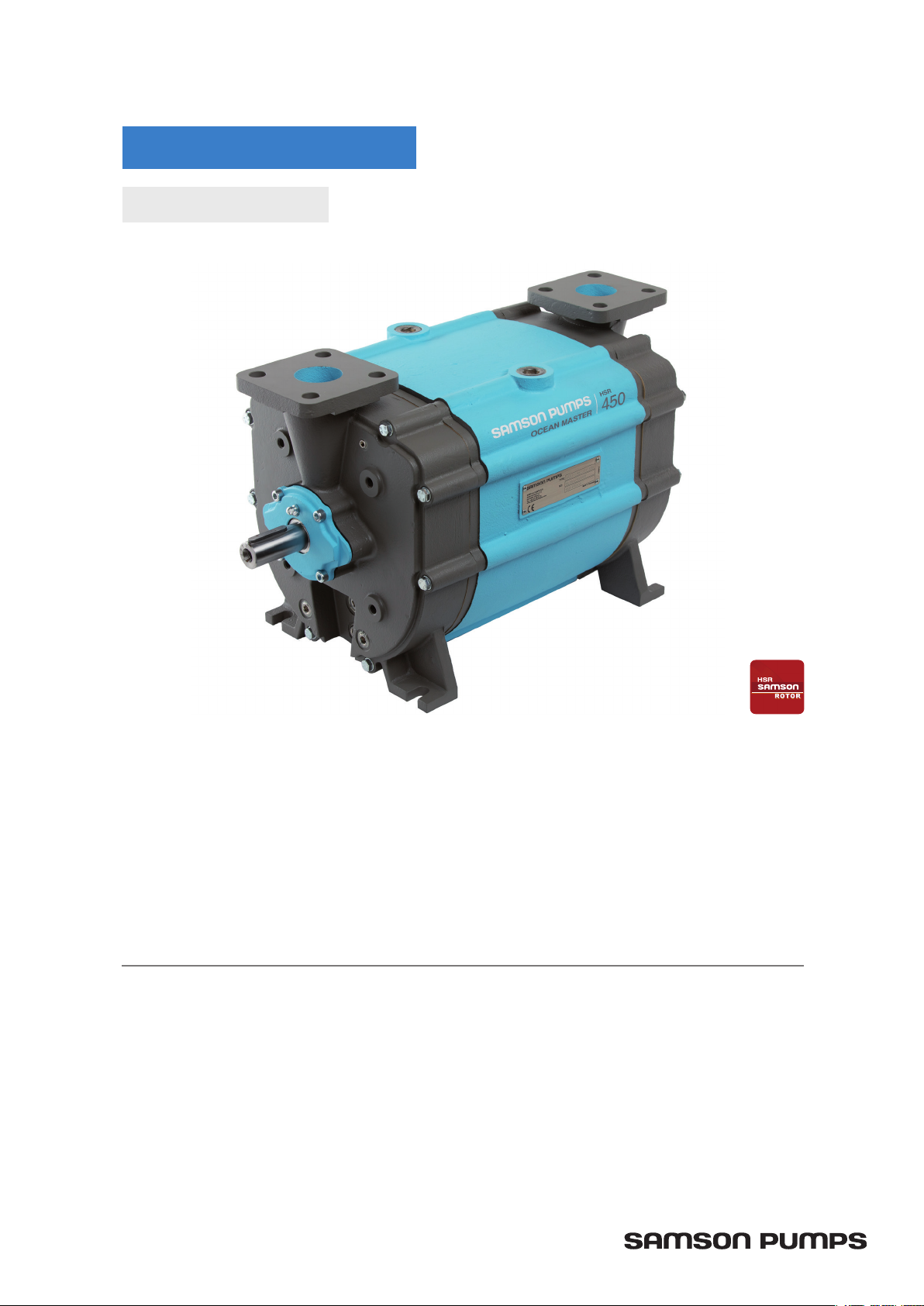
LIQUID RING PUMP
OCEAN MASTER® 450
INSTRUCTION MANUAL FOR SAMSON LIQUID RING PUMP
OCEAN MASTER 450
• Technical data
• Design of a system
• Installation and start-up
DOC9061D
• Service
• Troubleshooting
• Spare parts
Page 2

CONTENTS
1 Introduction .............................................................................................................................. 4
1.1 Declaration of conformity ........................................................................................................ 4
1.2 Explanation of warning symbols .............................................................................................. 5
1.3 Field of application .................................................................................................................. 5
1.4 Disposal .................................................................................................................................. 5
2 Technical data .......................................................................................................................... 6
2.1 Dimensions ............................................................................................................................. 6
2.2 Specifications .......................................................................................................................... 7
2.3 Power consumption and output ............................................................................................... 8
2.3.1 Performance ........................................................................................................................... 8
2.3.2 Consumption .......................................................................................................................... 9
2.4 Handling and transport ......................................................................................................... 10
2.5 Pump storage and draining procedure ................................................................................... 11
3 Design of a system ..............................................................................................................12
3.1 Piping ................................................................................................................................... 13
3.2 Service liquid adjustment ...................................................................................................... 13
3.3 Service liquid pump ............................................................................................................... 13
3.4 Pump performance ................................................................................................................ 14
3.5 Pressure drop ........................................................................................................................ 15
3.6 Service liquid requirement ..................................................................................................... 16
4 Installation and start-up ...................................................................................................17
4.1 Securing the pump ................................................................................................................ 17
4.2 Connections to the pump ...................................................................................................... 17
4.3 Connecting the service liquid ................................................................................................ 17
4.4 Transmission ........................................................................................................................ 17
4.5 Prior to start-up .................................................................................................................... 18
4.6 Direction of rotation ............................................................................................................. 18
5 Service, operation, maintenance and inspection intervals............................................. 19
5.1 Check grease cartridges ....................................................................................................... 19
5.2 Winterization ......................................................................................................................... 19
5.3 Lubrication of bearings ......................................................................................................... 20
5.4 Inspection and cleaning of service liquid’s supply pipe .......................................................... 20
5.5 Inspection and cleaning of internal channels ........................................................................ 20
2
Page 3

6 Troubleshooting ...................................................................................................................21
7 Spare parts and tools ..........................................................................................................22
7.1 Marking and identification ..................................................................................................... 22
7.2 How to order ......................................................................................................................... 23
7.3 Spare parts ............................................................................................................................ 24
7.4 Adaptor ................................................................................................................................. 28
7.5 Gasket set ............................................................................................................................. 29
7.6 Special tool set ...................................................................................................................... 30
Ocean Master 450
3
Page 4
E-Mail
Web www.samson-pumps.com Phone | +45 87 50 95 70 DK-8800 Viborg
1 INTRODUCTION
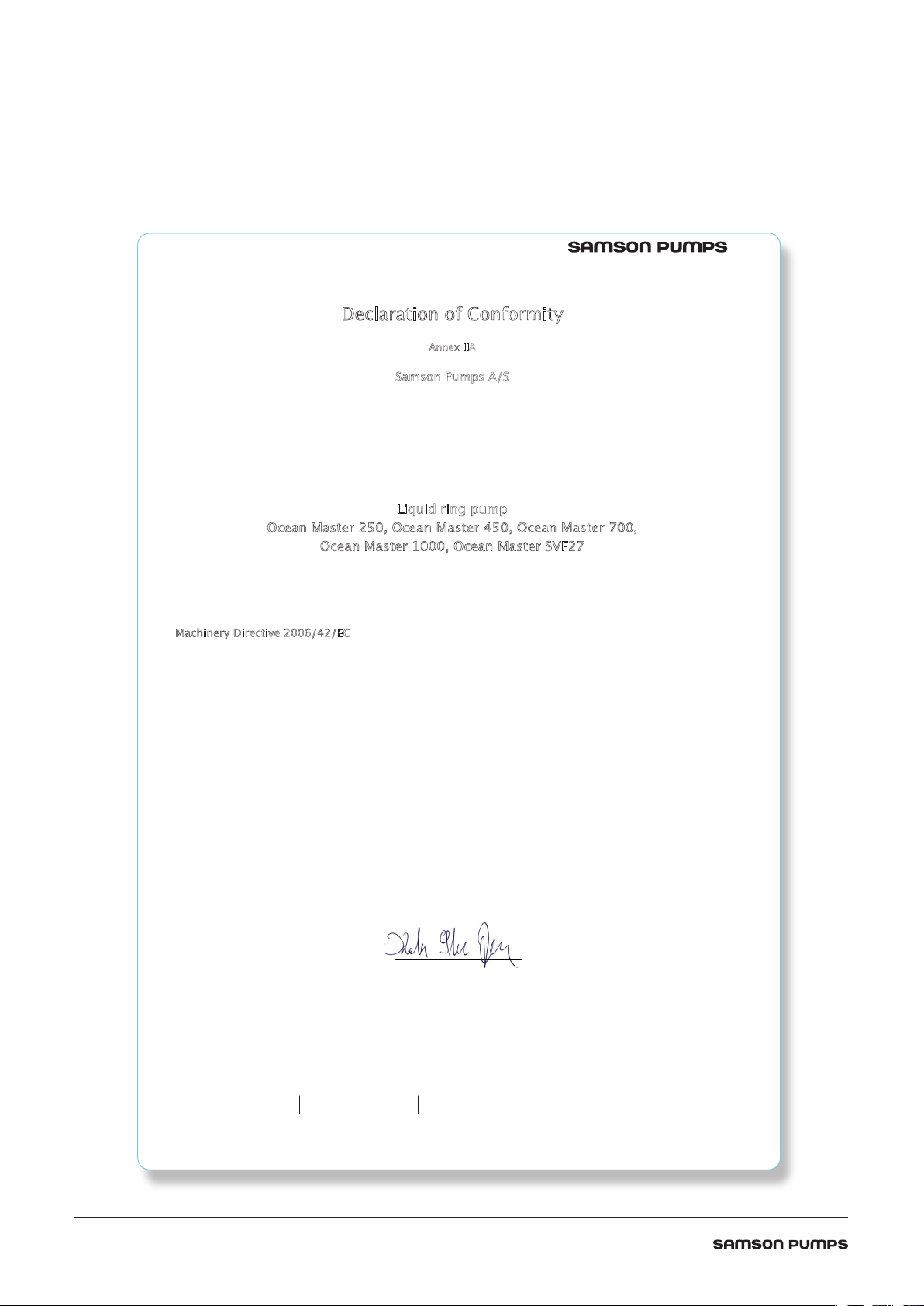
1.1 Declaration of conformity
Dec
Hereby declares that the following products:
cean Master 250, Ocean Master 450, Ocean Master 700,
O
cean Master 1000, Ocean Master SVF27
O
laration of Conformity
Annex IIA
Samson Pumps A/S
Petersmindevej 21
DK-8800 Viborg
Liquid ring pump
Conforms to the directive:
Machinery Directive 2006/42/EC
I hereby declare that the liquid ring pumps are in conformity with the following harmonized standards:
DS/EN ISO 12100:2011 Safety of machinery - General principles for design - Risk assessment and risk
DS/EN 1012-2 + A1:2009 Compressors and Pumps - Safety requirements - Part 2: Vacuum pumps
The standards above only apply to the extent that it is relevant for the purpose of the pump.
The product must not be used before the complete system, which it must be incorporated in, has been conformity
assessed and found to comply with all relevant health and safety requirements of 2006/42/EC and other relevant
directives. The product must be included in the overall risk assessment.
Viborg, 03.10.2018 _______________________
Kelvin Storm Jensen
R&D Manager
Samson Pumps A/S
reduction
DOC4045
DOC4045
info@samson-pumps.com Samson Pumps A/S Petersmindevej 21
4
Page 5
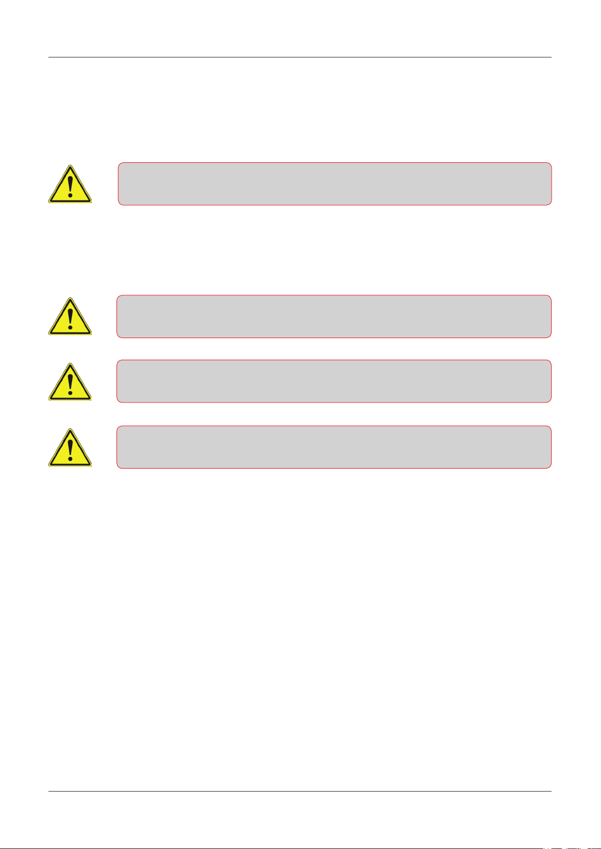
1.2 Explanation of warning symbols
Important technical and safety instructions are shown by symbols. If the instructions are not performed
correctly, it can lead to personnel injuries or incorrect function of the pump.
To be used with all safety instructions that must be followed. A failure to follow the
instructions may result in injuries and/or incorrect machine operation
1.3 Field of application
Inlet of foreign objects can damage the pump
The pump is designed exclusively to pump gases, including atmospheric air
WARNING!
Avoid cavitation of the pump! For further information, see instruction manual for the
Samson Pumps vacuum limiter
It must be ensured that the inlet gas cannot react with the service liquid and create aggressive bonds that
break down the pump's components.
For other operating data, see specifications.
• The pump must only be used with media that is not aggressive to the pump's materials. See section 7
for components and materials.
1.4 Disposal
Samson’s liquid ring pump is manufactured so that most of the device can be reused/recycled.
Samson Pumps offer users of the company’s pumps the option of returning used pumps to be restored or
scrapped.
Alternatively, the pump must be taken apart and sorted into its separate components, by the customer
(see section 7 for the pump’s material).
These components must be disposed of in accordance with national regulations.
Ocean Master 450
5
Page 6
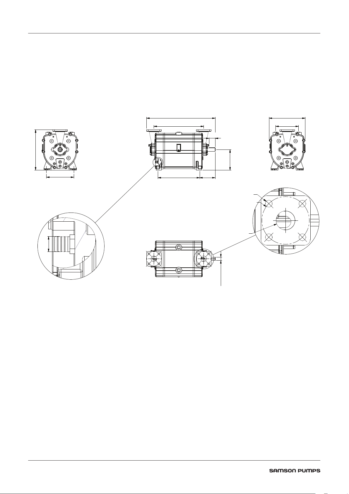
2 TECHNICAL DATA
355
20Ø
180
30Ø k6
2.1 Dimensions
240
603
437
54
317
200
367 136
Ø18
Ø125
Ø50
DOC1627396B
6
Page 7

2.2 Specifications
A failure to meet these specifications may result in damage to the pump
Description Minimum Maximum
Ambient temperature, operation Below 0°C - see chapter 5.3 -20°C 55°C
Ambient temperature, storage -20°C 55°C
Humidity - 100%
Intake temperature, suction side - 60°C
Intake temperature, service liquid - 60°C
Service liquid pipe connection, dimension ½” -
Service liquid pipe connection, length - 6 m
Noise level - 70 dB(A)
Water volume - 9 L
Maximum radial load on drive shaft - 1720 N
Revolutions 1200 rpm 1800 rpm
Pressure 150 mbar abs. 2 bar(g)
Lubricating grease
Weight 120 kg
Type of grease SKF LGWA2
Automatic lubrication SKF LAGD 125/WA2
Ocean Master 450
7
Page 8
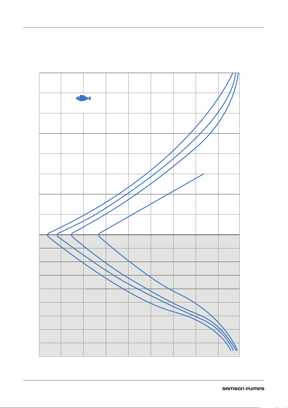
OCEAN MASTER 450
PERFORMANCE
POWER
kW
1200 RPM
450 400 350 300 250 200 150 100
5 10 15 20 25 307,5 12,5 17,5 22,5 27,5
5 10 15 20 25 307,5 12,5 17,5 22,5 27,5
2.3 Power consumption and output
2.3.1 Performance
m3/h
450 400 350 300 250 200 150 100
DISCHARGE HEIGHTSUCTION DEPTH
FISH
m3/h
1800 RPM
1650 RPM
1500 RPM
20,00
17,50
15,00
12,50
10,00
7,50
5,00
1200 RPM
2,50
0 m
- 1,00
- 2,00
- 3,00
- 4,00
- 5,00
- 6,00
- 7,00
- 8,00
m3/h
8
- 9,00
DOC11584
Page 9
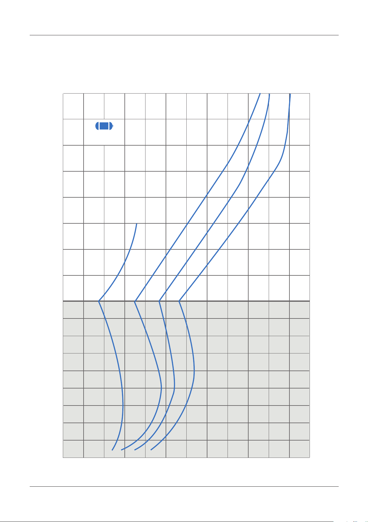
kW
kW
5 10 15 20 25 307,5 12,5 17,5 22,5 27,5
2.3.2 Consumption
5 10 15 20 25 307,5 12,5 17,5 22,5 27,5
20,00
17,50
15,00
12,50
10,00
7,50
5,00
POWER
kW
1200 RPM
1500 RPM
1650 RPM
1800 RPM
2,50
0 m
- 1,00
- 2,00
- 3,00
- 4,00
- 5,00
- 6,00
- 7,00
- 8,00
- 9,00
Ocean Master 450
DOC11584
9
Page 10
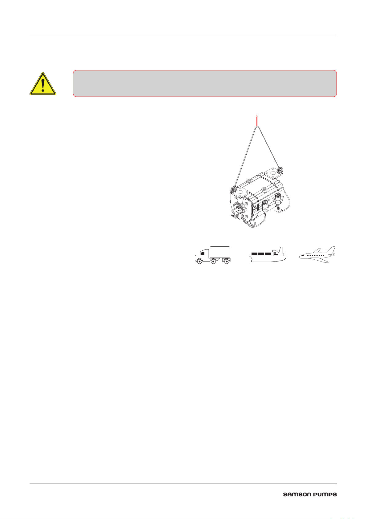
2.4 Handling and transport
The pump must not be used if it is damaged or the identification plate is missing
The pump must be transported in such way that it
is not exposed to vibrations and impacts that can
overload the bearings.
The pump must be inspected for damages upon
delivery. If the pump is damaged, it must not be used
and the damage must be reported to the manufacturer.
Ensure that the pump’s identification plate is intact and
that the marking of the pump corresponds to its use.
The pump must only be handled using approved
lifting eyes, in accordance with nationally applicable
regulations and only in a vertical motion.
DOC1627397
The pump can be transported in the following ways:
DOC11093A
10
Page 11

2.5 Pump storage and draining procedure
A
B
A failure to comply with the requirements for storing the pump may result in internal
damage to the device
If the temperature is below freezing point of the service liquid, it could damage the pump
Under these conditions, the pump must be drained completely
All plugs and protective covers must be fitted during storage
The pump’s service liquid is drained on delivery, and the pump can be immediately stored in accordance
with the technical specifications.
After operation, the pump can be stored for 30 days without further action.
If the pump remains out of operation for a longer period of time after use, its service liquid must be
drained, and the liquid supply to the pump must be shut off.
When emptying the pump, it is important that all chambers inside the pump are emptied.
The pump can be fitted with valves in the draining connections. See below.
After use with sea water it is recommended to drain and flush the pump with fresh water.
Ocean Master 450
DOC1627398
11
Page 12

3 DESIGN OF A SYSTEM
Pos. Description
1
2
3
4
5
6
7
Liquid ring pump
4-way valve
Pressure gauge
Regulating valve
Water pump
Pipe connection - Critical pipe
Stop valve
12
DOC1627418_1
Page 13

3.1 Piping
In a fish handling system, where the pump is working without liquid separator, the piping can be critical.
The pipe pos 6 will be a combination of a discharge and a suction pipe and the design of this pipe is very
important.
Figure below shows a standard setup. When the pump is discharging, the tank pipe pos 6 will carry a
mixture of air and water, which is the sealing water supplied to the pump. When the 4 way valve pos 2
change position this pipe becomes the suction pipe and water that is in the pipe will enter the pump. In
normal situation a small vibration will follow when the pump is injected with water on the suction side.
It is important to keep a high velocity > 30 m/s in this pipe and design it as short as possible without
“water traps”. The velocity can be calculated based on the nominel flow and the pipe diameter.
Another and safer solution is to place the 4 way valve closer to the fish tank as illustrated below.
DOC1627418_2
3.2 Service liquid adjustment
In order to get the correct water pressure to the pump it is recommended to build the supply line as
illustrated below. For correct service liquid supply, the neutral pressure needs to be adjusted to between
0,6 and 0,8 bar(g) when the pump is running unloaded.
DOC1627418_3
3.3 Service liquid pump
The water pump must be able to have a flow on 3000 l/h at a pressure at 1 bar(g) in order to get the full
performance of the liquid ring pump.
Ocean Master 450
13
Page 14

3.4 Pump performance
The pump performance can easily be found using the performance curves.
• Plot in the lifting height and add the calculated pressure drop in meter water column.
• Follow a horizontal line till you meet the performance curve.
• Go vertical down and read the performance.
For practical design it is important that the speed in the pipe system etc. is verified against a fish handling
perspective.
Note: 1 meter water column = 0,1 bar = 100 mbar
14
DOC1627419_1
Page 15

3.5 Pressure drop
The pressure drop in the system depends on the flow and on the other side the flow will depend on the
pressure drop.
It is a mathematical iteration process, therefore in practice we need to start the calculation with a guess.
As a start value for the flow it will be recommended to use the flow corresponding to the static lift + 1
meter corresponding to 0,1 bar or 100 mbar.
DOC1627419_2
It is possible to calculate the pressure drop manually, but there is a lot of free programs for download.
Use the system data to evaluate the pressure drop used as start value.
The calculated value can be used to find out if the start value is too low or too high.
Example
If the calculated pressure drop is far below the start value (100mbar) make a new calculation with the flow
based on for example 50 mbar. Start with the static pressure + 50 mbar and find the flow from the curve.
If the calculated pressure drop is far above the start value (100 mbar), make a new calculation with the
flow based on for example 200 mbar. Start with the static pressure + 200 mbar and find the flow from the
curve.
NOTE: Pressure drop above 100 mbar indicates that your pipe diameter is too small for the pump you are
using.
Ocean Master 450
15
Page 16

3.6 Service liquid requirement
If sea water is used as sealing water, it is recommended to flush the pump with fresh water after use and
drain the pump afterwards.
Before the pump is started again, remember to fill the pump to about shaft height before start up.
Otherwise the pump will be started with dry run of the mechanical shaft seals, which will shorten the
lifetime.
A drain valve mounted in the pump will help to identify the correct level of water. See below.
DOC1627398_2
16
Page 17

4 INSTALLATION AND START-UP
B
B
4.1 Securing the pump
Installation requirements must be observed, otherwise there is a risk of damage
The pump must be installed on a stable foundation, which must
be level and stable, so that the pump is not twisted or exposed
to a profile distortion.
The pump must be installed with M12 bolts on all four legs,
which must be tightened to 60 Nm (A).
A
4.2 Connections to the pump
• Check for foreign objects in the pump and physical damage on pump
• Gaskets to be handeled with highest degree of caution
• Gasket and sealing surfaces must be cleaned before assembly
DOC1627400_1
Immediate before connecting the pipes, remove protective
covers. Connection of the pump’s suction and pressure pipe
connections must be made with a gasket in between (C).
The M12 bolts must be tightened with 60 Nm (B).
In order to prevent tensions in the pump, the pipe connections
(A) must be tensionless while tightening the bolts.
4.3 Connecting the service liquid
The service liquid must be connected to the pump at the hose connection, see
illustration.
A
B
C
DOC1627400_2
DOC1627398_1
4.4 Transmission
The pump can be connected direct or through belt transmission. For belt transmission, it must be ensured
that the permissible radial force is not exceeded. See specifications.
Ocean Master 450
17
Page 18

4.5 Prior to start-up
• Do not start the pump without service liquid, as this will damage the mechanical shaft
seals
• Do not start the pump if it is completely filled with service liquid
• Do not start the pump before the grease cartridges have been activated, as this can
damage the pump (if equipped)
• Stop the pump immediately if the rotational direction does not correspond to the
directional arrow
• A failure to follow the above guidelines may result in damage to the pump
Activating the grease cartridges (Accessories)
Turn the handle in NDE clockwise to position 12.
Turn the handle in DE clockwise to position 12.
The pump has been lubricated from factory and is ready to start.
DOC3707
NDE
DOC1627396_1
DE
4.6 Direction of rotation
Check the direction of rotation by briefly starting the pump.
The direction of rotation of the rotor must correspond to the direction arrow!
Below left, a right-side pump is shown which has a clockwise direction of rotation (CW)
Below right, a left-side pump is shown which has a counter-clockwise direction of rotation (CCW)
18
DOC1627399
DOC1627399_1
Page 19

5 SERVICE, OPERATION, MAINTENANCE AND INSPECTION INTERVALS
A failure to observe the inspection intervals described in table below may result in
damage to the pump
Section Operation Interval
5.1 Check grease cartridges (if equipped) Weekly
5.2 Winterization When below 0°C
5.3 Lubrication of bearings Per 500 duty hours
5.4 Inspection and cleaning of service liquid’s supply pipe Monthly
5.5 Inspection and cleaning of internal channels Monthly
5.1 Check grease cartridges
If the pump is equipped with an automatic lubrication feature. It must be inspected and
replaced as needed.
When the pump is commissioned for the first time, the cartridges must be activated by
turning the arrow in the clockwise direction.
The cartridge is set to 12, which corresponds to an emptying time of 12 months.
The cartridge must be replaced when empty.
It is only allowed to use automatic lubricator of type LAGD 125/WA2.
DOC3707
5.2 Winterization
If the pump needs to be used at a temperature below freezing point of the service liquid, it is necessary to
protect the liquid from freezing by adding anti freeze liquid.
Ocean Master 450
19
Page 20

5.3 Lubrication of bearings
Over-lubrication of bearings may result in bearing damage! Do NOT exceed the
amount of grease specified below!
The bearings must be lubricated with grease of type SKF LGWA2, per 500 duty hours.
It is recommended to lubricate the bearings while pump is running.
Lubrication interval per 500 duty hours
Drive end (DE) 2 g
Non drive end (NDE) 2 g
NDE
DE
DOC1627396_3
5.4 Inspection and cleaning of service liquid’s supply pipe
The pipe connection between the liquid separator and pump must be inspected at least once a month, and
any contaminants must be removed.
5.5 Inspection and cleaning of internal channels
The pump is designed with internal water channels for lubrication of the mechanical shaft seals.
Remove the plug as illustrated below and clean the channel using a ø5 mm 150 mm long screw driver or
similar.
20
DOC1627398_3
Page 21

6 TROUBLESHOOTING
Problem Cause Effect Corrective measure
The pump is unable to
create a vacuum
The start-up power is
too high
Noise during operation • Cavitation
• Service liquid valve is
closed
• The pump is not
receiving enough
service liquid
• The temperature of the
service liquid is too
high
• Too much service liquid
in the pump prior to
start-up
• Too much water
in the pipe system
when switching from
pressure to vacuum
• Reduced output
• The pump can become
damaged during
cavitation
• Noise at start-up and
possible overload of
the power supply
• Severe damage to the
pump and potential risk
of breakdown
• Check service liquid
valve
• Check the liquid
supply
• Stop the pump
and wait until
the temperature
has dropped to
a sufficient level,
or lower the
temperature of the
service liquid inlet
• Check the stop valves
in the liquid supply
for leakage
• Adjust the service
liquid pressure
• Redesign the pipe
system (critical pipe)
Leakage from the
bearing housing’s drain
holes
• Damaged shaft seal • Bearings may become
damaged
• Potential risk of
explosive gas leak
• Stop the pump
and contact the
manufacturer
Ocean Master 450
21
Page 22

7 SPARE PARTS AND TOOLS
Location of ID plate
7.1 Marking and identification
The pump is equipped with an identification plate as shown below.
CE CONFORMITY MARK
ORDER CONFIRMATION NO. / A NO.
Configuration example:
Type:
Model:
Rotation:
Rotor type:
Pump housing:
Shell:
Flow plates:
Mechanical shaft seals:
Gaskets:
Colour:
MANUFACTURING DATE / SERIAL NO.
PRODUCT CODE
OM
450 R 0 S S B 0 0 S SD
Documentation:
22
DOC107942
Page 23

7.2 How to order
Example:
Model:
450
Rotation:
Clockwise
Counter clockwise
Rotor type:
Welded AISI 316
Pump housing:
Cast iron EN-GJL-250; EN1561
Shell:
Cast iron EN-GJL-250; EN1561
Flow plates:
Cast iron EN-GJL-250; EN1561
Stainless steel AISI 316
OM 450 R 0 S S S 0 0 P SD
450
R
L
0
S
S
S
E
Mechanical shaft seals:
NBR / AISI 316
Gaskets:
Oakenstrong
Colour:
Grey primer
Ocean Master Blue
On request
Documentation:
Samson standard
ATEX Zone 1
ATEX Zone 0
0
0
P
S
X
SD
X1
X5
Ocean Master 450
23
Page 24

24 14
13
32
7
10
16
17
8
22
12
9
34
2
11
21
29
28
30
19
3
20
23
5
16
25
33
37
4
44
45
40
39
38
42
41
43
48
7.3 Spare parts
*
*
*
*
24
*
Page 25

3
20
23
18
32
6
31
15
27
35
36
4
26
47
46
1
*
Ocean Master 450
- Included in gasket set.
*
DOC1627396_2
25
Page 26

Pos. Part number Description Qty. Material
1 1623013 Shell 1 Cast iron
2 1623057 Pump housing 2 Cast iron
3*
4 910300182 Plug 2 Steel
5*
6 1623061 Bearing cover NDE 1 Cast iron
7 1623062 Bearing cover DE 1 Cast iron
8 930000081 Ball bearing 2 Steel
9 1601003 Gasket set Ocean Master 450 1 -
10 1601003 Gasket set Ocean Master 450 1 -
11 - Direction arrow 1 Aluminum
12 915000197 Grease nipple 2 Steel
13 910000020 Bolt 16 Steel
14 910300024 Allen screw 8 Steel
15 925000246 Hose nipple 1 Brass
16 910300188 Plug 7 Brass
17 910300184 Plug 1 Brass
18 - Identification plate 1 Stainless steel
1623030 Flow plate 1 Cast iron
1623004 Flow plate 1 Stainless steel
1623005 Rotor R 1 Stainless steel
1623059 Rotor L 1 Stainless steel
19 922000042 Mechanical shaft seal 2 Steel
20 1601003 Gasket set Ocean Master 450 1 -
21 1601003 Gasket set Ocean Master 450 1 -
22 1601003 Gasket set Ocean Master 450 1 -
23 910300447 Allen screw 6 Stainless steel
24 915000210 Parallel key 1 Steel
25 1623025 Ball guide 1 Plastic
26 910300459 Allen screw 1 Steel
27 1623026 Ball guide 1 Plastic
28 910100004 Washer 6 Stainless steel
29 910000130 Bolt 6 Stainless steel
30 962000046 Valve Ball 16 Plastic
31 1623063 Washer 1 Stainless steel
32 910100007 Washer 16 Steel
33 1601003 Gasket set Ocean Master 450 1 -
34 1623065 Adjustment plate 2 Cast iron
35 910300125 Socket set screw 2 Steel
* -See section 7.1 for identification of pump.
**-Optional. Not equipped as standard.
26
Page 27

Pos. Part number Description Qty. Material
36*
37 1624020 Sticker Warning! 2 Plastic foil
38 910300281 Plug 4 Steel
39** 915000225 Automatic lubricator LAGD 125/WA2 2 Plastic / grease
40** 915000232 Clamp for automatic lubricator 2 Plastic
41** 944600239 Push-in nipple 2 Brass
42** 944600173 Elbow 2 Brass
43** 944600240 Elbow 2 Brass
44** 910300221 Allen screw 2 Steel
45** 910100002 Washer 2 Steel
46 1623027 Spacer for ball guide 2 Stainless steel
47** 915000217 Plastic pipe 0,3 m Plastic
48** 915000217 Plastic pipe 0,3 m Plastic
1623032 Flow plate 1 Cast iron
1623015 Flow plate 1 Stainless steel
* -See section 7.1 for identification of pump.
**-Optional. Not equipped as standard.
Ocean Master 450
27
Page 28

7.4 Adaptor
9
10
8
3
4
2
1
5
7
6
Pos. Part number Description Qty. Material
1 1613110 Bush 4 Steel
2 1634738 Adaptor for hydraulic motor 1 Steel
3 910000160 M12x25 set screw 4 Steel
4 910100016 M12 washer 4 Steel
5 910300182 Plug 1” 1 Steel
6 910300445 M12x40 socket set screw 4 Steel
7 915000054 Grease nipple 1 Steel
8 932400120 Rubber element 1 Rubber
9 932400121 Half coupling 2 Cast iron
10 932300029 Taperlock bush 2 Cast iron
DOC1627401_1
28
Page 29

7.5 Gasket set
DOC11592
Pos. Part number Description Qty. Material
9 922200051 Radial shaft seal 45x65x8 2 Rubber / Steel
10 922200036 Radial shaft seal 40x55x7 1 Rubber / Steel
20
21 1623023 Gasket for pump housing / flow plate 0,4 mm 2 Paper
22
33 922100359 O-ring Ø74,50x3,00 2 Rubber
1623022 Gasket for shell / flow plate 0,4 mm 2 Paper
1623055 Gasket for shell / flow plate 0,8 mm 2 Paper
1623066 Gasket for bearing cover 1 mm 2 Rubber
1623024 Gasket for bearing cover 0,4 mm (<2012) 2 Paper
See spare parts drawing (DOC1627396_2) for positions.
Ocean Master 450
29
Page 30

7.6 Special tool set
7
8
2
3
6
4
1
5
Pos. Part number Description Qty. Material
DOC1629268_1
1 1629136 Bearing tool 1 Steel
2 1629196 Mandrel radial shaft seal Ø30 + Ø45 1 Plastic
3 1629197 Mandrel mechanical shaft ring 1 Plastic
4 1629194 Guide pin M8 2 Steel
5 910300428 Socket set screw 2 Steel
6 1629193 Bearing mounting tool 1 Plastic
7 1629079 Assembly bush 2 Plastic
8 1629195 Mandrel radial shaft seal Ø35 1 Plastic
30
Page 31

Notes:
Ocean Master 450
31
Page 32

SAMSON PUMPS
Samson Pumps is the only company in the world to specialise exclusively in
liquid ring vacuum pumps. Samson pumps are made in Denmark and used
around the globe. We offer worldwide delivery, and we export to more than 80
countries around the world.
For over 40 years, our name has been synonymous with the strongest pumps
for vacuum trucks and tankers. We constantly adapt our products to meet the
changing needs of our customers. Today, it is not enough to simply produce a
pump. Products must be refined so the customer can concentrate on what they
do best. We therefore offer a wide range of standardised components that allow
our customers to build vacuum systems without the need for specialist in-house
expertise.
Strength and durability are our hallmarks! We have often heard from customers
that our pumps are working in many years, and in most cases without the need
for maintenance or repair. This emboldens us to say that we have the strongest
program of pumps on the market.
E-Mail info@samson-pumps.com Samson Pumps A/S Petersmindevej 21
Web www.samson-pumps.com Phone | +45 87 50 95 70 DK-8800 Viborg
 Loading...