

Page 1
Specifications subject to change without notice
Edition
EN
The device may only be mounted and started
Operating, assembly and maintenance instructions
BR 31a Rack-and-pinion Actuator,
SRP and DAP
1. General
These instructions are intended to support the user in the
assembly, maintenance, and repair of BR 31a Rack-and-
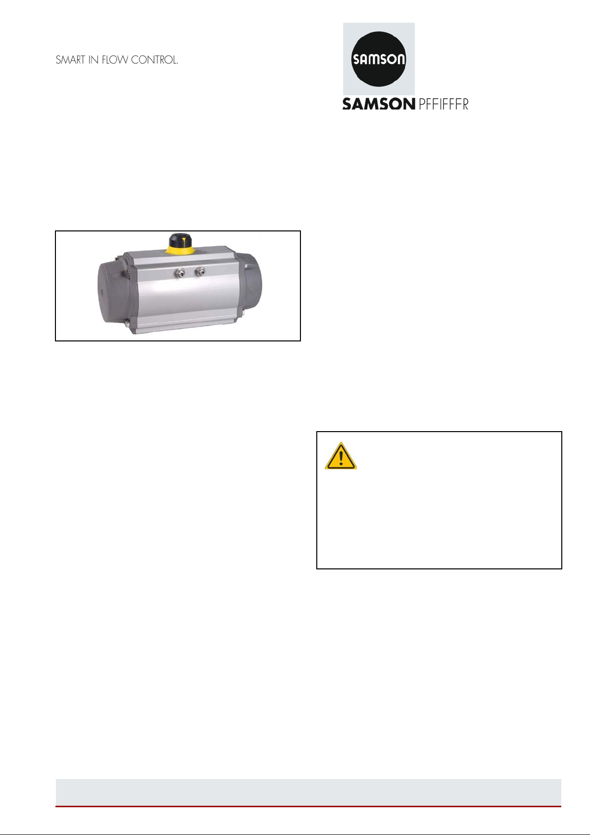
Fig. 1 - Rack-and-pinion actuator
0. Contents
1. General 1
2. Design, principle of operation, and dimensions 1
3. Actuator designation and nameplate 1
4. Operating conditions 2
4.1 Design 2
4.2 Warnings 2
4.3 Operating media 3
4.4 Supply pressure 3
4.5 Operating temperatures 3
4.6 Response time 3
4.7 Rotation and travel limitation 3
4.8 Lubrication 3
4.9 Coating and corrosion protection 3
4.10 Function and direction of rotation 4
4.11 Fail-safe position 4
5. Actuator design und mounting instructions 4
5.1 Principle of operation 4
5.2 Important safety instructions 5
5.3 Control and connections 5
5.4 Mounting accessories 5
5.5 Mounting the actuator onto valves 6
5.6 Changing the direction of action/fail-safe position 6
5.7 Alternative mounting options 6
6. Maintenance and assembly instructions 7
6.1 Fourth generation of rack-and-pinion actuators
(version manufactured from 2000)
6.2 Third generation rack-and-pinion actuators 13
7. Storage instructions 18
8. Customer inquiries 18
1 of 18
pinion Actuators.
Before operating the unit, please read this manual thor ough l y
and retain it for future reference.
Technical specifications, as a result of further development of
valves mentioned in these instructions are subject to
alteration without notice.
The text and illustrations do not necessarily display the scope
of supply or any ordering of spare parts.
Drawings and graphics are not to scale. Customer-specific
designs not in accordance with our standard product range
are not shown.
Parts subject to wear are not covered by the warranty.
up by skilled staff who are familiar with the
assembly, start-up, and operation of this
product.
In these maintenance and assembly instructions, the term
skilled staff refers to individuals who are able to judge the
responsibilities assigned to them as well as recognize
potential hazards due to their specialized training,
knowledge, and experience as well as their special
knowledge of the relevant standards.
These instructions apply to the actuator only. In addition,
refer to the instructio ns of the moun ted valv e.
2. Design, principle of operation, and dimensions
Design, principle of operation, and dimensions including all
further details and technical data can be found in the Data
Sheet <TB 31a>.
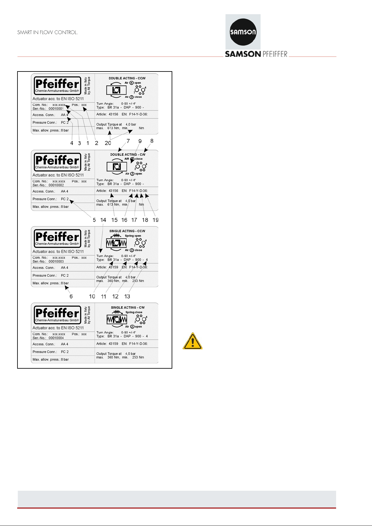
3. Actuator designation and nameplate
The actuator type, size, operating pressure, output torque,
direction of rotation, fail-safe action, operating temperature,
and type of attachment are determined by the actuator
designation.
: August 2017 Maintenance EB 31a-01_
Page 2
Specifications subject to change without notice
Edition
EN
• Maxi mum per mis si ble pr ess ur e (fixed)
6 Always 10 bar for BR 31a
• Pr inciple of opera tion (variable)
7 Actuator function: Single-acting/double-acting
8 Direction of action : CW = Clockwise
CCW = Counterclockwise
9 Schematic diagram of the spring function with the air
connection. Schematic diagram of NAMUR interface
with identification for ports 2 and 4
• Exact type designation (variable)
10 Series: BR 31a
11 Type: SRP / DAP
12 Actuator size: 6 to 10000
13 Spring design ation: 2,5 to 6 (bar)
• Opening angle (fixed, depending on actuator size)
14 0-90° +5/-15°; 0-120°+/+5/-15°; 0-180° +5/-15°;
• Article number (variable)
15 Pfeiffer article number
• Version acc. to EN (fixed, depending on actuator size)
Example: F07-Y-D-17
16 Flange F07
17 Spigot ( Y )
18 Diagonal square drive ( D )
19 Square drive, width across flats 17
• Torques (variable)
20 Specification of the actuator torque depending on
supply pressure.
Fig. 2 – Name plates
Rack-and-pinion actuators have nameplates, which show the
following information:
• Unique identification (variabel)
1 Order number
2 Position number in the order
3 Serial number (automatically assigned)
• Connection for accessories (fixed, depending on
actuator size)
4 AA1 to AA5 (VDE/VDI actuator size 1 to 4)
• Pressure connection (fixed, depending on actuator size)
5 PC1 = G 1/8“ PC3 = G 3/8“
PC2 = G 1/4“ PC4 = G 1/2“
2 of 18
4. Operating conditions
4.1 Operating conditions
The rack-and-pinion actuator is suitable for use in closed and
open environments without additional weather protection.
4.2 Warnings:
• Referring to the Machinery Directive 2006/46/EU, the
actuators can be classified as “partly completed
machinery” (see declaration of incorporation).
As a result, the actuator cannot put into service until the
machinery and/or the system, into which the actuator is to
be incorporated, has been declared in conformity with the
provisions of the Directive 2006/42/EU.
• Actuators are designed, produced, and classifi ed
according to the ATEX Directive 2014/34/EU.
The use of the actuators in potentially explosive
atmosphere zones must comply with the ATEX
classification indicated on the actuator nameplate and
according to the ATEX safety regulations.
• It is important that the actuator is used only within the
working limits permitted in the technical specifications.
: August 2017 Maintenance EB 31a-01_
Page 3
Specifications subject to change without notice
Edition
EN
Manufacturer
Lubricant
Tennex
TS 2066/2
• Do not operate the actuator outside the temperature
limits: this could damage internal and external
components (disassembly of single-acting actuators may
be dangerous).
• Do not operate the actuator outside the pressure limits:
this could damage internal parts as well as cause damage
to the housing and end caps.
• D o not use the actuator in corrosive environments with
insufficient protection: this could damage internal and
external parts.
• D o not disassem ble ind iv idua l sprin g cartridges; this may
result in personal injury. If maintenance to springs is
necessary, send them to Pfeiffer.
• C lose and disco nne ct all air su pply lines and ma ke sure
that pneumatic connections are vented during
maintenance and when mounting the actuator onto the
valve.
• Do not disassemble the actuator or remove the end caps
while the actuator is pressurized.
• The actuators are designed to be used only on valves.
• Bef ore mou ntin g the actuator onto the valve, make sure
that the direction of rotation and the position indicator are
in the correct position.
• If the actuator is incorporated into a system or must be
used in safety devices or circuits, the operator must
ensure that the national and local safety laws and
regulations are observed.
4.3 Operating media:
Dry or lubricated air or inert gases, provided that they are
compatible with the actuator’s internal parts and lubricant
used.
Note: The operating media must have a dew point
equal to -20 C (-4°F) or at least 10°C below the
ambient temperature. The maximum particle size
contained into the operating media must not
exceed 30 μm.
Note: For operation at low and high temperatures,
special lubricant is required. Please contact
Pfeiffer. A low or high temperature can slightly
influence the torque of the actuator.
4.6 Response time:
Refer to the corresponding data sheets for the response
times.
Note: The response time depends on several
factors, e.g. supply pressure, supply capa city of
the operating medium (pipe diameter, flow
capacity of pneumatic accessories), valve type, valve torque
and characteristics, applied safet y factor, o perat ing fr equ enc y
and temperature etc.).
4.7 Rotation and travel li m itation:
Refer to the data sheet for the travel of the rack-and-pinion
actuators:
Standard actuator: 90° rotating angle, with end stop
setting at 0° and 90°, +5/–15°
adjustable
120° actuator: 120° rotating angle with end stop
setting at 0° and 120°, +5/–15°
adjustable
180° actuator: 180° rotating angle with end stop
setting at 0° and 180°, +5/–15°
adjustable
4.8 Lubrication:
The actuators are delivered ready lubricated for the service
life of the actuator under normal operating conditions. The
standard lubricant is approved for the temperature range from
-40°C (-40°F) to +80 C (+176°F).
For low (SLT) and high (HT) temperatures, a special lubricant
is required. Contact Pfeiffer in this case.
4.4 Supply pressure:
The maximum supply pressure is 10 bar (145 psi).
For double-acting and single-acting actuators, the operating
pressure range is 2.5 bar (36 psi) to 10 bar (145 psi).
4.5 Operating temperatures:
• Standard actuator:
from -40°C (-40°F) to +80°C (+176°F).
• Low-temperature version SLT with silicone O-rings:
from -55°C (-67°F) to +80°C (+176°F).
• High-temperature version HT with FPM O-rings:
from -15°C (+5°F) to +150°C (+300°F).
3 of 18
: August 2017 Maintenance EB 31a-01_
Table 1 - Lubricant recommendation
4.9 Coating and corrosion protection:
All actuators are protected against corrosion under normal
weather conditions. The different types of coating are
described in the data sheet
Note: Before mounting the actuator in a corrosive
environment, make sure that the correct type of
corrosion protection has been chosen.
Page 4
Specifications subject to change without notice
Edition
EN
4.10 Function and direction of rotation:
The actuator is a pneumatic component for remote actuation
of valves. For the actuation (90°, 120° or 180° rotation), there
are different actuator versions:
• Direct mounting of a solenoid valve (5/2 or 5/3-way for
double acting, 3/2-way for single acting) for connecting to
ports 2 and 4.
• Hook-up (to ports 2 and 4) with a separate control unit.
• The standard direction of rotation is the clockwise
direction to close a mounted valve. The counterclockwise
direction for double-acting actuators is achieved by
applying air pressure to port 2.
• For actuat ors mar ked “CCW”, the direction of rotation to
close the valve is counterclockwise, the clockwise
direction of rotation (CW) is achieved by applying air
pressure to port 2.
4.11 Fail-safe position:
• Fail-close: clockwise (SRP only)
• Fail-open: counterclockwise (SRP only)
Fig. 4 - CCW direction
If the shaft of the actuator is to turn in a clockwise direction
when the valve opens, the pistons must be installed in the
opposite way to the standard version (see Fig. 4).
The shaft turns from the start position OPEN to the end
position CLOSED in clockwise direction (SRP only). The
actuator is delivered in the start position.
Fig. 3 - CW direction
The standard version of the Series 31a Actuators is mounted
in the direction of the media flow.
When pressure is applied to port 2, the shaft turns from the
start position CLOSED to the end position OPEN in the
counterclockwise direction.
In case of pressure loss at port 2, the shaft turns clockwise to
the start position CLOSED (SRP only). The actuator is
delivered in the start position.
Note: If mounted diagonal to the media flow, make
sure that the position indicator is set correctly (turn
90°, see mounting instructions
4 of 18
5. Actuator design und mounting instructions
The BR 31a Actuator operates with a 90° (optionally 120° or
180°) angle of rotation to open and close different types of
valves
Note: All the necessary technical information to
correctly mount the actuator onto a valve, e.g.
dimensions, output torque, air volume, travel
adjustment, response time, operating temperature, and
direction of rotation are clearly stated on the nameplate, in
the catalog and/or data sheets.
Read the technical information carefully before proceeding
with mounting the actuator.
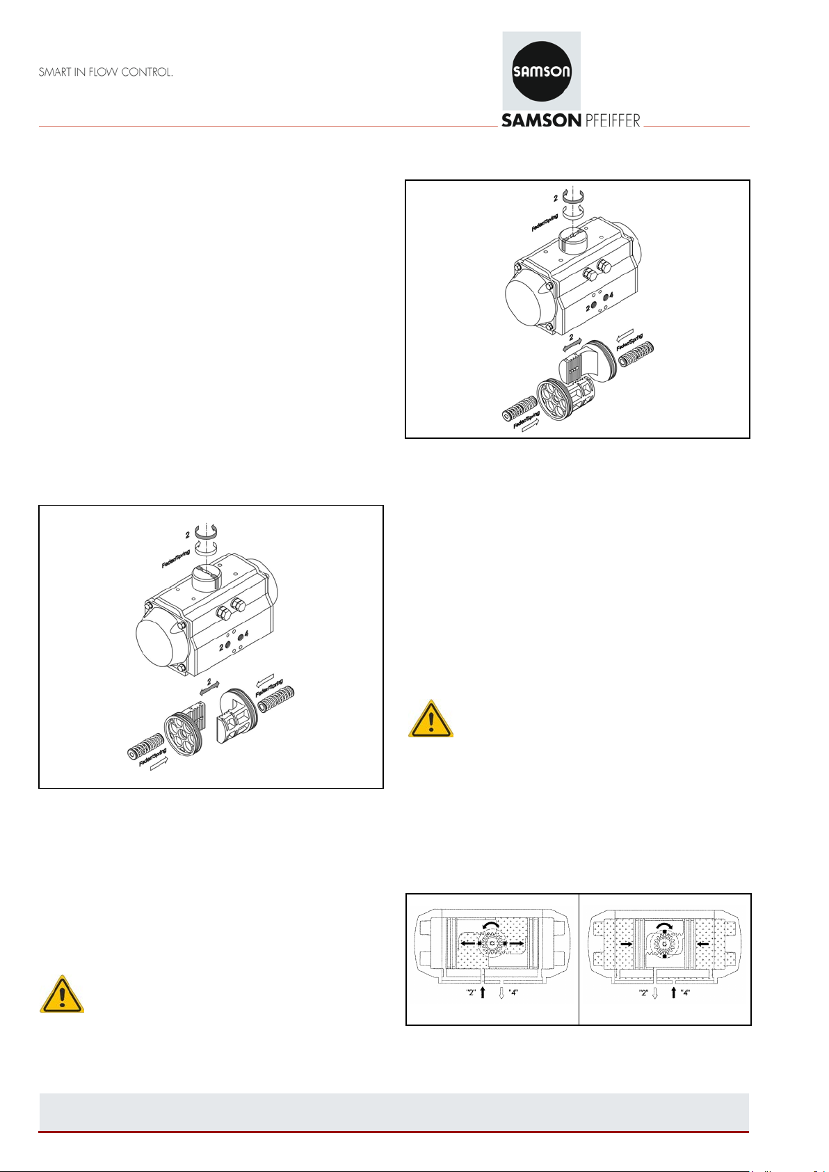
5.1 Principle of operation:
• Double-acting actuator (standard direction of rotation)
Fig. 5
Fig. 6
: August 2017 Maintenance EB 31a-01_
Page 5
Specifications subject to change without notice
Edition
EN
Screw
M5
M6
M8
M10
M12
M14
M16
M20
M24
M30
Tightening
in NM
5
6
10
11
23
25
48
52
82
86
132
138
200
210
390
410
675
705
1340
1400
Air supplied to port 2 (Fig. 5) forces the pistons apart and
towards the end positions. Air is vented at port 4. This is
based on a clockwise direction of rotation.
Air supplied to port 4 (Fig. 6) forces the pistons together. Air
is vented at port 2. This is based on a clockwise direction of
rotation.
• Single-a cting actuat or (standard direction of rotation)
Fig. 7
Fig. 8
Air supplied to port 2 (Fig. 7) forces the pistons apart and
towards the end positions. The springs are compressed. Air is
vented at port 4. This is based on a clockwise direction of
rotation.
A loss of air pressure at port 2 (Fig. 8) allows the pistons to
return to the start position. Air is vented at port 2. This is
based on a clockwise direction of rotation.
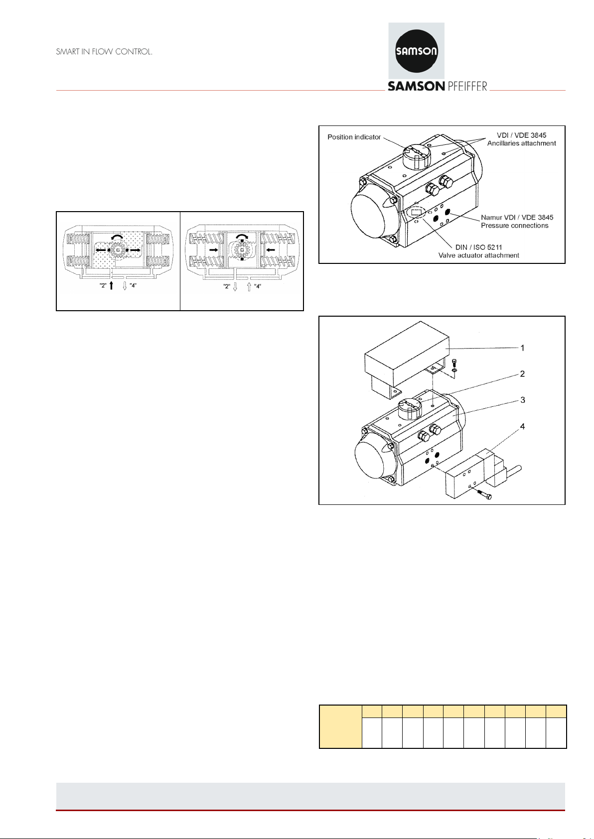
5.3 Control and connecti o ns:
Fig. 9 – Connections
5.4 Mounting accessories
5.2 Important safety instr u ctions
• For safety reasons, the actuator must not be pressurized
when mounting the actuator onto the valve. Risk of injury.
• When connecting the air pressure to the actuator, it is
important that all connecting parts are clean and free from
dirt, especially the thread connections, pipe screw fittings,
and gaskets.
• When fitting accessories to the actuator, make sure that
the emergency operator control of the solenoid valve and
the top end of the shaft are easily accessible for possible
manual operation of the actuator.
• Before mounting the actuator onto the valve, make sure
that the actuator is correctly aligned based on the direction
of rotation required.
• For single-acting actuators, make sure dan ger ou s and/or
corrosive substances in the working environment cannot
enter the spring chambers through the use of suitable
filters and/or solenoid valves.
• Remove plugs from the actuator’s pneumatic connections
during installation and operation. Protect any unused
pneumatic connections of actuators.
5 of 18
Fig. 10 - Mounting accessories
• Mounting the solenoid valve:
Before mounting the solenoid valve, check that the
actuator is in the initial posit ion (closed position, pistons
retracted). For standard mounting and clockwise rotation
(closing): The groove on the shaft or position indicator (2)
must be in the closed position, at a right angle to the
longitudinal axis of the actuator. Mount the solenoid valve
(4) onto the actuator (3) using the suitable screws (see
Table 2 for max. tightening torque).
• Mounting the limit switch box:
Fit the limit switch box and bracket (1) onto the actuator
(3) using suitable screws (see Table 2 for max. tightening
torque).
torque
Table 2 - Tightening torque
bis
bis
bis
bis
bis
bis
bis
bis
bis
bis
: August 2017 Maintenance EB 31a-01_
Page 6
Specifications subject to change without notice
Edition
EN
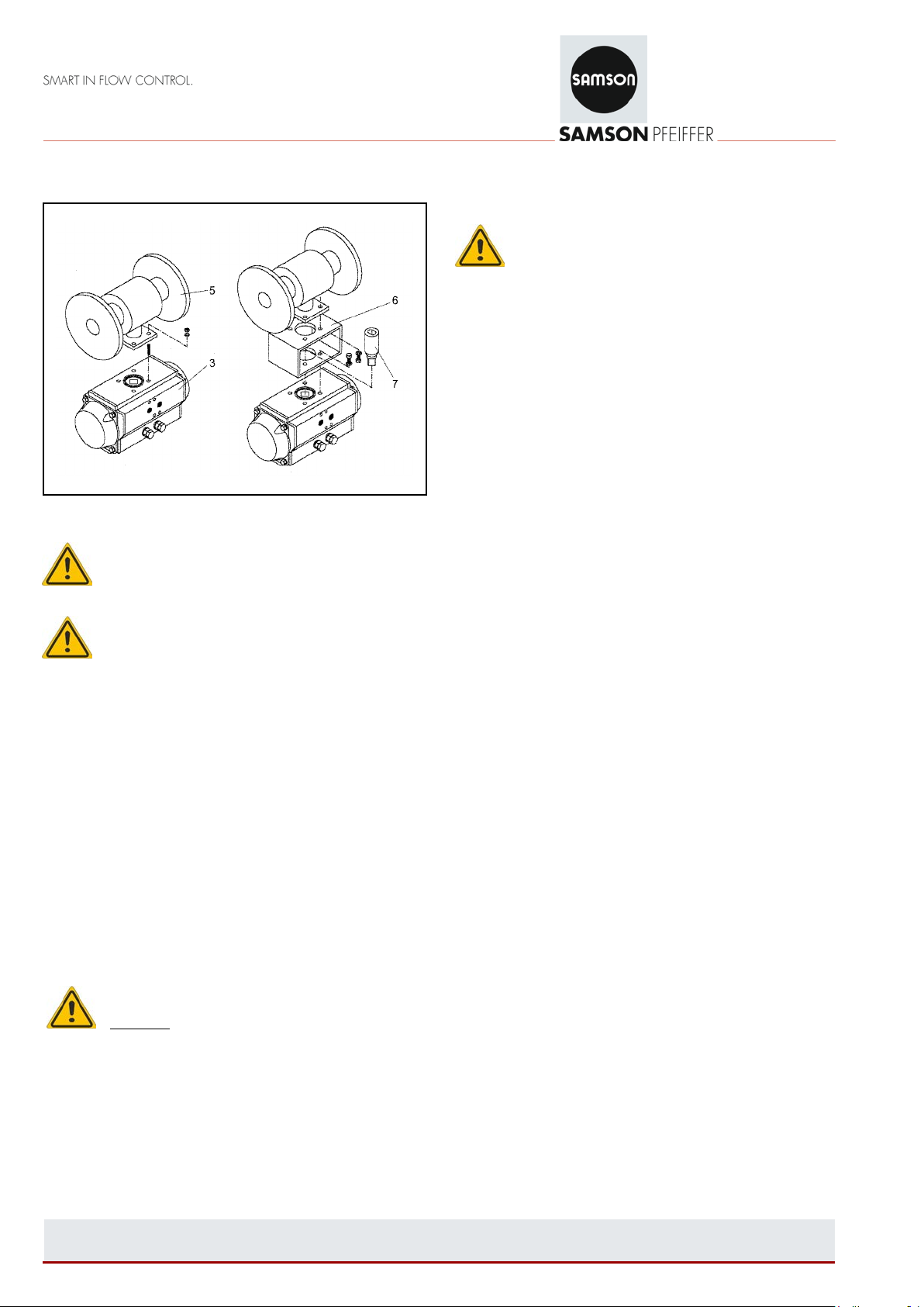
5.5 Mounting the actuator onto valves:
Fig. 11 - Mounting the actuator onto valves
Note: Before mounting the actuator onto a valve,
ensure that the actuator turns in the required
direction of rotation and that the valve and actuator
are correctly aligned with each other.
Caution: When mounting a single-acting actuator
(with spring) with a defined fail-safe position,
ensure upon pneumatic or electric power failure
that the direction of rotation is according to your application.
(clockwise to close).
Mount the actuator ( 3 ) onto the valve ( 5 ). The actuator
must be in the initial position (CLOSED position).
There are two different mounting versions:
• Direct mounting:
Insert either the square drive, flat head drive or key drive
of the valve shaft directly into the actuator shaft. Fasten
them using the ISO flange onto the actuator. See Table 2
for max. tightening torque.
• Mounting using a bracket:
Mount the bracket (6) onto the valve (5) and place the
coupling (7) onto the actuator shaft.
Note: Make sure that the position indicator of the
coupling corresponds with the switching position of
the valve.
Place the actuator onto the shaft and fasten the unit. See
Table 2 for max. tightening torque.
6 of 18
5.6 Changing the direction of action/fail-safe position
Note: For the exact procedure for disassembly and
assembly, refer to section 6 (maintenance and
assembly instructions).
• Move the actuator to the fail-safe position to release the
spring compression.
• Remove the screws ( 24 ) (see Fig. 15).
• Pull the position indicator ( 19 ) off the end of the shaft. If
necessary, use a screwdriver to lever it off.
• Remove both adjusting screws ( 2 ) with washers ( 4 ) and
lock nuts ( 3 ) (see Fig. 16).
• Remove the O-ring ( 11 ).
• Unscrew the screws ( 13 ) of the end caps (see Fig. 17).
• Remove end caps ( 22 und 23 ) from the housing.
• For single-acting actuators, remove the spring cartridges
( 17 ).
• Remove the gaskets ( 14 ) of the end caps.
• C lamp the hou sing ( 29 ) in a vise or similar. Turn the
shaft ( 30 ) until the pistons ( 25 ) are released
(see Fig. 18).
• Turn both pistons ( 25 ) in axial direction by 180° and
reassemble.
• Press both pistons ( 25 ) simultaneously into the housing
( 29 ) until they engage and turn the housing until the
travel end position is reached.
• Check that the pistons are in the end position. Turn the
shaft 4° over the center line (0°) (see Fig. 25).
• For single-acting actuators, insert the spring cartridges
into the end caps (see Fig. 27).
• Insert the gasket ( 14 ) into the groove of both end caps.
• Mount the end caps on the housing ( 29 ).
• Tighten the screws ( 13 ) by hand. Observe the tightening
sequence (see Fig. 28).
• Insert the adjusting screws ( 2 ), lock nuts ( 3 ), washers
( 4 ), and O-rings ( 11 ).
• Screw the adjusting screws ( 2 ) into the housing.
• Observe the end position setting.
• Place the position indicator ( 19 ) onto the shaft. Make
sure that it is in the correct position (see Fig. 30).
• Tighten screw ( 24 ).
5.7 Alternative mounting opti o n s:
• Alternative mounting options
(in clockwise direction to open)
: August 2017 Maintenance EB 31a-01_
Page 7

Specifications subject to change without notice
Edition
EN
Actuator
DAP/SRP
d
in mm
SW 1
in mm
SW 2
in mm
SW 3
in mm
SW 4
in mm
15
14
10
10 8 3
30
16
10
10
10
3
60
22
13
13
10 4 100
25
13
13
10 4 150
26
17
17
13 5 220
36
19
19
13 6 300
38
19
19
17 6 450
45
22
22
17 6 600
48
22
22
19
6
900
52
24
24
19 8 1200
58
30
30
22
10
2000
68
30
30
24
10
3000
80
36
36
22
12
4000
85
46
46
24
17
5000
90
46
46
24
17
10000
102
24
60
Allen 14
-
Fig. 12 - Clockwise direction to close
• Val v e mounted with an actu ator :
(in clockwise direction to open)
6.1 Fourth generation of rack-and-pinion
actuators (version manufactured from 2000)
6.1.1 Screw sizes
Table 3 - Dimensions
Fig. 13 - Clockwise direction to open
6. Maintenance and assembly instructions
With the information stated below, Pfeiffer provides the end
user with all the required information necessary for
maintenance. Under normal operating conditions, the
actuator requires only periodic checks to ensure proper
functioning.
Spare part kits for maintenance are available to replace all
seals and bearings. Maintenance may be necessary between
500,000 and 1,000,000 cycles, depending on the operating
and/or environmental conditio ns.
7 of 18
: August 2017 Maintenance EB 31a-01_
Fig. 14 - Screw sizes (depending on actuator version)
Page 8

Specifications subject to change without notice
Edition
EN
Item
Qty.
Description
Material
Item
Qty.
Description
Material
1 1 Cam (end position adjustment)
GS400-15
16 2 O-ring (piston)
NBR
2 2 Adjusting screw
A2-70
17
4 - 12
Spring cartridge
SiCr spring steel
3
2
Lock nut
A2-70
18 1 Spring clip
C 75
4
2
Washer
A2
19 1 Position indicator
PP + 30% GF
5 2 Bearing (piston back)
Nylon 46
20 1 Shaft seal (bottom)
NBR
6 1 Shaft bearing bushing (top)
PA 46
21 1 Shaft seal (top)
NBR
7 1 Shaft bearing bushing (bottom)
PA 46
22 1 Right end cap
GD-AlSi8.5Cu3.5Fe
8 2 Thrust bearing
Nylon 46
23 1 Left end cap
GD-AlSi8.5Cu3.5Fe
9 2 Plug (to seal air port)
NBR
24 1 Screw (position indicator)
A2-70
10 1 Thrust washer
1.4301
25
2
Piston
GD-AlSi8.5Cu3.5Fe
11 2 O-ring (adjusting screw)
NBR
26 1 Nameplate
Polyester aluminium
12 2 Piston guide
Nylon 66 + 30% GF
27 2 Nameplate (end cap)
Polyester aluminium
13
8/12/16
Screw (end cap)
A2-70
28
1
Spigot
EN AW 6063
14 2 Gasket (end cap)
NBR
29
1
Housing
EN AW 6063
15 2 Bearing (piston head)
POM
30
1
Shaft
C22
Fig. 15 - Detailed drawing of Series 31a Actuator, version manufactured from 2010
Table 4 - Parts list
8 of 18
: August 2017 Maintenance EB 31a-01_
Page 9

Specifications subject to change without notice
Edition
EN
6.1.2 Disassembly of the actuator:
When the actuator must be disassembled for maintenance
purposes, first remove the actuator from the valve.
Note: Before disassembly, it is important to check
that the actuator is not pressurized and the
compression is relieved from the actuator springs
(end position).
Always use caution and check that ports 2 and 4 are vented
and that all accessories are removed.
Before disassembling a single-acting actuator, make sure that
the actuator is in the start position and the pistons fully
retracted.
• Removing the position indicator
(see Fig. 16)
◦ Remove screw ( 24 ).
◦ Lift position indicator ( 19 ) from shaft. If necessary,
use a screwdriver to lever it off.
• Removing the adjusting screws:
(actuator versions manufactured up to 2006) (see Fig. 17)
◦ Remove both adjusting screws ( 2 ) with the washers
( 4 ) and lock nuts ( 3 ).
◦ Remove O-rings ( 11 ) and replace them when
replacing spare parts.
• Remov i ng adjusting scr e ws:
(actuator versions manufactured from 2006) (see Fig. 17)
◦ Remove lock nuts ( 3 ) together with washers ( 4 ).
◦ Remove O-rings ( 11 ) and renew them when
replacing spare parts
◦ Unthread both adjusting screws ( 2 ) and continue
unscrewing until their stopping point. Before
continuing with the final disassembly, remove the end
caps ( 22 and 23 ) and the pistons ( 25 ) since the
adjusting screws can only be removed from the inside
of the housing. The instructions for dismantling the
end caps and pistons are described below.
• Removing the end caps
(see Fig. 18)
For sizes 900 to 3000, the end caps ( 22 and 23 ) are
symmetric.
◦ Remove the screws ( 13 ) in the sequence a-b-c-d
(see Fig. 18).
Note: When disassembli ng a single-acting
actuator, loosen the screws of the end caps ( 22
and 23 ) in alternating sequence.
If there is still noticable force after 4 or 5 turns on all end cap
screws, this may indicate a damaged spring cartridge, and
any further disassembly should be discontinued. Further
disassambly of the end caps may result in injury.
Return the actuator to Pfeiffer for further maintenance.
◦ For single-acting actuators, remove spring cartridge
( 17 ).
◦ Remove gasket ( 14 ) and renew it when replacing
spare parts.
Fig. 16
Fig. 17
Fig. 18
9 of 18
: August 2017 Maintenance EB 31a-01_
Page 10

Specifications subject to change without notice
Edition
EN
• Removing the pistons:
(see Fig. 19)
◦ Clamp the housing ( 29 ) in a vise or similar device.
Turn the shaft ( 30 ) until the pistons ( 25 ) are
accessible.
Note:
Do not apply air pressure to remove the pistons
from the housing (projectile impact).
◦ Carefully remove the piston O-rings ( 16 ) using a
screwdriver. Remove the piston bearing ( 5 ) and
piston bearing ( 15 ).
Renew gasket ( 14 ) when replacing spare parts.
• Remov i ng the shaft
(see Fig. 20)
◦ Use pliers for circlips to carefully remove the spring
clip ( 18 ). Remove the thrust bearing ( 8 ) and thrust
washer ( 10 ).
◦ Push down on the top of the shaft ( 30 ) until it is
possible to remove the cam ( 1 ) and the internal thrust
bearing ( 8 ). Pull the shaft ( 30 ) all the way out of the
housing.
If the shaft cannot be removed by hand, gently tap the
top of the shaft with a plastic mallet to drive it out.
◦ Remove the top and bottom shaft bearings ( 6 and 7 )
as well as top and bottom shaft seals ( 20 and 21 ).
◦ Renew the bearing bushings ( 6 and 7 ), internal and
external thrust bearing ( 8 ) as well as the seals ( 20
and 21 ) when replacing all the spare parts.
Note: Thoroughly clean all dismantled parts as well
as any parts that have not been renewed and
check them for wear.
6.1.3 Actuator assembly:
Note: Before assembly, ensure that all parts are
clean and in perfect condition. Use the grease
recommended by Pfeiffer (Table 1).
• Shaft assembly
(see Fig. 21, Fig. 22a and Fig. 22b)
◦ Mount the top and bottom bearing bushings ( 6 and 7 )
followed by the top and bottom shaft seals ( 20 and
21 ) onto the shaft.
◦ Apply grease to the top and bottom of the shaft as
shown in Fig. 21.
◦ Guide the shaft ( 30 ) partially into the housing ( 29 )
◦ Mount the cam ( 1 ) in the required position, in relation
to the top and bottom position of the shaft as well in
relation to the direction of rotation of the actuator (see
Fig. 22).
◦ Place the internal thrust bearing ( 8 ) onto the shaft
( 30 ). Guide the shaft completely into the housing.
◦ Mount the external thrust bearing ( 8 ), thrust washer
( 10 ), and spring clip ( 18 ) (using pliers).
Fig. 19
Fig. 20
Fig. 21
10 of 18
: August 2017 Maintenance EB 31a-01_
Page 11

Specifications subject to change without notice
Edition
EN
Fig. 22a
Fig. 23
Fig. 24
Fig. 22a
Note: For actuators from 2006:
The adjusting screws ( 2 ) of this act uator ver sio n
are mounted from the inside, into the actuator
housing. This step must carried out before the piston and end
caps are mounted.
• Mounting the pistons
(see Fig. 23, Fig. 24, Fig. 25a, Fig. 25b, and Fig. 26)
◦ Mount the the piston O-ring ( 16 ), piston bearing ( 5 ),
and piston bearing ( 15 ).
◦ Apply grease to the bearing surface of the piston ( 25 )
inside the housing ( 29 ) and the piston rack teeth.
◦ Either clamp the top end of the shaft in a vise or hold
the shaft stationary with the corresponding counterpar t
and place the housing ( 29 ) in a horizontal position
(see Fig. 23).
◦ Make sure that the cam ( 1 ) is in the correct position
(see Fig. 24).
◦ For the standard direction of rotation (clockwise to
close), turn the housing ( 29 ) by 40° to 45°
counterclockwise (view from below) or clockwise (view
from top), depending on which way the shaft is held
(see Fig 25a and Fig. 25b).
◦ Press both pistons ( 25 ) simultaneously into the
housing ( 29 ) until the pistons are engaged and turn
the housing clockwise or counterclockwise (see
above) until the travel end is reached.
◦ Check the pistons in the end position and turn the
shaft 4° over the middle line (0°) (see Fig. 26).
11 of 18
Fig. 25a
Fig. 25b
Fig. 26
: August 2017 Maintenance EB 31a-01_
Page 12

Specifications subject to change without notice
Edition
EN
• Mounting the end caps
(see Fig. 27, Fig. 28 and Fig. 29)
For actuator sizes 900 to 3000, the end caps ( 22 and 23 )
and spring cartridges ( 17 ) are symmetric (Figs. 27, 28
and 29).
◦ Bearing surface of the housing.
◦ For single-acting actuators, insert the correct number
of spring cartridges (according to table) into the end
caps (see Figs. 27 and 28).
◦ Fit gaskets ( 14 ) into the grooves of both end caps.
◦ Mount the end caps onto the housing ( 29 ), making
sure that the gaskets are seated properly in the
grooves.
◦ Tighten the screws ( 13 ) by hand. Tighten according
to the sequence indicated in Fig. 29.
• Mounting the adjusting screws
(actuator versions manufactured up to 2006) (see Fig. 30)
◦ Insert adjusting screws ( 2 ), lock nuts ( 3 ), washers
( 4 ) and O-rings ( 11 ).
◦ Screw the adjusting screws ( 2 ) into the housing.
• Mounting the adjusting screws
(actuator versions manufactured from 2006) (see Fig. 30)
◦ Both adjusting screws ( 2 ) must be screwed into the
housing before the pistons and end caps are
mounted because they can only be inserted from the
inside of the actuator.
◦ Insert the O-rings ( 11 ).
◦ Place the lock nuts ( 3 ) and washers ( 4 ) onto the
adjusting screws.
• Adjusting the end position on the standard actuator
(in clockwise direction to close)
◦ 0° (closed) end position adjustment for an actuator in
the closed position: turn the screw ( 2 ) on the right
(view from the top) either clockwise or
counterclockwise until the required position is
achieved.
To secure this position, tighten the lock nut ( 4 ).
◦ 90° (open) end position adjustment for an actuator in
the open position: turn the screw ( 2 ) on the left
(view from the top) either clockwise or
counterclockwise until the required position is
achieved.
To secure this position, tighten the lock nut ( 4 ).
Fig. 28
Fig. 29
Fig. 27
12 of 18
: August 2017 Maintenance EB 31a-01_
Fig. 30
Page 13

Specifications subject to change without notice
Edition
EN
• Mounting the position indicator
(see Fig. 31)
◦ Place the position indicator ( 19 ) on the shaft, making
sure that it is in the correct position.
◦ Tighten screw ( 24 ).
Fig. 31
The actuator assembly is now completed.
Fig. 32
6.2 Third generation rack-and-pinion actuators
6.2.1 Actuator disassembly
Note: Before disassembly, it is important to check
that the actuator is not pressurized and all
accessories (e.g. solenoid valv es or limit sw itche s)
have been removed.
Refer to the detailed drawing of actuator (Fig. 39).
• Removing the cam or position indicator (if fitted)
(see Fig. 32)
◦ Open the spring clip ( 18 ) using a suitable pair of
pliers.
Note:
Make sure that the spring clip is not stretched too
far.
◦ Use a tool (e.g. screwdriver) to lift the cam up slightly.
• O-ring replacement on angle adjusting screw OPEN
(see Fig. 33)
◦ Undo nut ( 12 ) using a socket w r ench.
◦ Unthread the adjusting screw ( 10 ) and remove the
washer ( 11a ) and O-ring ( 11 ). This must be done on
both sides.
◦ After renewing the O-ring ( 11 ), slightly tighten the nut
(without locking) to tighten the adjusting screw with O ring and washer.
◦ The two adjusting screws are first to be locked
properly once the final assembly has been completed
and on adjusting the piston.
13 of 18
Fig. 33
Fig. 34
• Removing the end caps
(see Fig. 34)
◦ Unscrew the screws ( 13 ) in the sequence shown in
Fig. 34. For Type SRP (single-acting), remove the
compression springs ( 17 ) as well.
◦ Renew gasket ( 14 ).
: August 2017 Maintenance EB 31a-01_
Page 14

Specifications subject to change without notice
Edition
EN
• O-ring replacement (with stop screw OPEN)
• (see Fig. 35)
◦ Undo nut ( 12 ) using a socket w r ench.
◦ Unthread the adjusting screw ( 10a ) and remove t he
washer ( 11a ) and O-ring ( 11 ). This must be done on
both sides.
◦ After renewing the O-ring ( 11 ), slightly tighten the nut
(without locking) to tighten the adjusting screw with O ring and washer.
◦ The two adjusting screws are first to be locked
properly once the final assembly has been completed
and on adjusting the piston.
• Removing the piston
(see Fig. 36)
◦ After removing the end caps, hold the housing ( 1 )
stationary (possibly in a vise) and turn the shafts until
the the pistons on both sides are released.
◦ Remove both the pistons on both sides.
◦ Use a flat, blunt tool (e.g. screwdriver) to remove the
O-ring ( 16 ), piston head bearing ( 15 ), and piston
back bearing ( 5 ).
◦ Check that both pistons are free of dirt particles,
especially at the gears. Renew the O-ring, piston head
bearing ( 15 ), and piston back bearing ( 5 ).
• Removing the shaft and bearing bushings
(see Fig. 37 and Fig. 38)
◦ Remove the spring clip ( 18 ) using pliers for circlip s
and the thrust washer ( 8 ).
◦ Push the shaft from the top downward out of the
housing (see Fig. 37).
◦ Remove the top and bottom bearing bushings ( 6 and
7 ) as shown in Fig. 38.
Fig. 36
Fig. 37
Fig. 35
14 of 18
: August 2017 Maintenance EB 31a-01_
Fig. 38
Page 15

Specifications subject to change without notice
Edition
EN
Item
Qty.
Description
Material
Item
Qty.
Description
Material
1
1
Housing
AlMgSi0,5 F25
12
4
Lock nut
X5 CrNi 18 10
2
2
Piston
GD-AlSi8 Cu3
13 8 Screw (end cap)
X5 CrNi 18 10
3
2
End cap
GD-AlSi8 Cu3
13a
8
Washer
X5 CrNi 18 10
4
1
Shaft
C22
14 2 Gasket (end cap)
Buna N
5 2 Bearing (piston back)
PA 4.6
15 2 Bearing (piston head)
PA 4.6
6 1 Shaft bearing bushing (top)
PA 4.6
16 2 O-ring (piston)
Buna N
7 1 Shaft bearing bushing (bottom)
PA 4.6
17
12
Spring cartridge
54 Si Cr6
8 1 Thrust washer
PA 4.6
18 1 Spring clip (pinion)
C75
8a 1 Support screw
X5 CrNi 18 10
19 1 Position indicator
PA
9 2 Air port screw
Buna N
20 1 Screw/washer
X5 CrNi 18 10
10 2 Adjusting screw (OPEN)
X5 CrNi 18 10
21 1 O-ring (pinion top)
Buna N
10a 2 Adjusting screw (CLOSED)
X5 CrNi 18 10
22 1 O-ring (pinion bottom)
Buna N
11 4 O-ring (adjusting screw)
Buna N
24 2 Guide piston
PPA
11a
4
Washer
X5 CrNi 18 10
25 1 Centering ring
PA
Fig. 39 - Detailed drawing of BR 31a Actuator, third generation
Table 5 - List of parts
15 of 18
: August 2017 Maintenance EB 31a-01_
Page 16

Specifications subject to change without notice
Edition
EN
6.2.2 Actuator reassembly after replacement of parts
• Mounting the actuator shaft and bearing bushings
(see Fig. 40, Fig. 41, Fig. 42, and Fig. 43)
◦ Apply grease to the shaft as shown in Fig. 40.
◦ Push the top bearing bushing ( 6 ) onto the shaft ( 4 ).
◦ Apply grease to the surface of the bearing bushing
( 7 ) and the shaft ( 4 ) as shown in Fig. 41.
◦ Apply grease to the surface of the bearing bushing
( 7 ) and mount the bushing as shown in Fig. 42.
◦ Use the special tool (available from Pfeiffer) to hold
the bearing bushing ( 7 ) stationary while pressing in
the shaft ( 4 ).
We recommend clamping the tool into a vise as shown
in Fig. 43.
After mounting the shaft, place the thrust washer ( 19 )
on the top shaft end. Mount the spring clip ( 18 ) using
pliers for circlips.
Fig. 40
Fig. 43
• Mounting the pistons
(see Fig. 44a, Fig. 44b, and Fig 45)
◦ Apply grease to the inside running surface of the
housing ( 1 ).
◦ Clamp the flattened section of shaft in a vise and
position the housing in the horizontal position.
◦ Align the tooth profile vertically as shown in Fig. 44a
and push the two pistons into the housing.
To obtain a counterclockwise rotation to close the
valve, install the pistons turned by 180° (see Fig. 44a).
◦ Turn the housing by 15° to 20° counterclockwise as
shown in Fig. 44b.
Fig. 41
Fig. 42
16 of 18
: August 2017 Maintenance EB 31a-01_
Fig. 44a
Fig. 44b
Page 17

Specifications subject to change without notice
Edition
EN
◦ Push and turn the housing onto the pistons clockwise
until the end of travel is reached. Check that the
internal angle adjusting screw does not reduce the
travel. This is not necessary if it is to be 90° to 95°.
◦ The shaft clearance is 3° to 5° more than 0°
(see Fig. 45).
Fig. 46
• Adjusting the opening angle for 0° position CLOSED
◦ To adjust, turn the adjusting screw ( 10a ) until the
required position is reached and lock this position with
the nut ( 12 ) using a socket wrench. While locking in
position, hold the adjusting screw stationary with an
Allen key.
◦ To ensure that both pistons stop at the same time, turn
the adjusting screw at the other piston until you feel
resistance and they stop at the shaft.
Lock the adjusting screw in the same position with the
lock nut ( 12 ).
◦ The initial position CLOSED has now been adjusted.
• Mounting the end caps and compression springs
(see Fig. 46 and Fig. 47)
◦ Apply grease to the housing.
◦ Insert the correct number of compre ssion springs
( 17 ) specified in Fig. 46 and according to the pattern
shown in Fig. 46.
◦ Fit on the end caps ( 3 ) and check to ensure that the
gaskets ( 14 ) are seated properly.
◦ Insert the screws ( 13 ) without screwing them tight.
Tighten them according to the sequence shown in
Fig. 47.
• Adjusting the switching position to 90° position OPEN
(see Fig. 48)
◦ External adjustment can only be made after the
actuator assembly is completed with the pistons
extended as far as they will go on the outside of the
housing as shown in Fig. 48.
◦ In double-acting actuators, this can be done by turning
the shaft. When the actuator has been mounted onto
the valve, apply the control pressure to move it to this
switching position.
Once you have adjusted the switching position on one
side, turn the screw on the other side as far as it will
go and lock this position.
17 of 18
Fig. 45
◦ For single-acting actuators (SRP), apply the control
pressure to move the actuator to the switching
position. Check this position, readjust, and move the
actuator to the position again until the required
position is reached.
◦ Lock the adjusting screw, while using an Allen key to
hold the screw stationary and lock it with a special key
(available from Pfeiffer).
The actuator assembly is now completed.
Fig. 47
Fig. 48
: August 2017 Maintenance EB 31a-01_
Page 18

Specifications subject to change without notice
Edition
EN
PDF=166
7. Storage instructions
lf the actuators are not for immediate use, the following
measures must be taken:
• Store them in dry environment at normal ambient
temperature.
• We recommend to leave the actuators in their original
packaging.
• Do not remove the plastics plugs on the air supply ports 2
and 4.
8. Customer inquiries
(please specify the following details)
Type of actuator: BR31a Typ DAP oder Typ SRP
Size: 15, 30, 60, 100, 150, 220, 300, 450,
600, 900, 1200, 2000, 3000, 4000,
5000 oder 10000
Number of springs: only with single-acting Type SRP
Fail-safe position: Clockwise or counterclockise rotation
of springs (only with single-acting
Type SRP)
Supply pressure: .... bar
Operating range: Number of springs or nominal signal
range
VDI/VDE bracket: To mount positioner or indicating
devices
18 of 18
: August 2017 Maintenance EB 31a-01_
 Loading...