

Samson AWX User Manual

Micro Wireless System
OWNER'S MANUAL

Copyright 2017, Samson Technologies Corp. v2
Samson Technologies Corp.
278-B Duffy Ave
Hicksville, NY 11801
www.samsontech.com
Important Safety Information
ATTENTION
RISQUE D’ÉLECTROCUTION !
NE PAS OUVRIR !
This lightning flash with
arrowhead symbol within
an equilateral triangle is
intended to alert the user to
the presence of non-insulated
“dangerous voltage” within the
product’s enclosure that may
be of sufficient magnitude to
constitute a risk of electric
shock.
CAUTION: TO REDUCE THE RISK OF ELECTRIC SHOCK, DO NOT REMOVE COVER
(OR BACK). NO USER-SERVICEABLE PARTS INSIDE. REFER SERVICING TO
QUALIFIED SERVICE PERSONNEL.
WARNING
TO PREVENT FIRE OR SHOCK HAZARD. DO NOT USE THIS PLUG WITH AN EXTENSION CORD, RECEPTACLE OR OTHER OUTLET UNLESS THE BLADES CAN BE FULLY
INSERTED TO PREVENT BLADE EXPOSURE. TO PREVENT FIRE OR SHOCK HAZARD.
DO NOT EXPOSE THIS APPLIANCE TO RAIN OR MOISTURE. TO PREVENT ELECTRICAL SHOCK, MATCH WIDE BLADE PLUG TO WIDE SLOT AND FULLY INSERT.
If you want to dispose this product, do not mix it with general household waste.
There is a separate collection system for used electronic products in accordance
with legislation that requires proper treatment, recovery and recycling.
Private household in the 28 member states of the EU, in Switzerland and Norway
may return their used electronic products free of charge to designated collection
facilities or to a retailer (if you purchase a similar new one).
For Countries not mentioned above, please contact your local authorities for a correct
method of disposal.
By doing so you will ensure that your disposed product undergoes the necessary
treatment, recovery and recycling and thus prevent potential negative effects on the
environment and human health.
The exclamation point within an
equilateral triangle is intended
to alert the user to the presence
of important operating and
maintenance instructions in
the literature accompanying the
appliance.
ENGLISHFRANÇAISDEUTSCHEESPAÑOLITALIANO
AirLine ATX Wireless System 3

Important Safety Information
1. Read these instructions.
2. Keep these instructions.
3. Heed all warnings.
4. Follow all instructions.
5. Do not use this apparatus near water.
6. Clean only with dry cloth.
7. Do not block any ventilation openings.
Install in accordance with the
manufacturer’s instructions.
8. Do not install near any heat sources
such as radiators, heat registers,
stoves, or other apparatus (including
amplifiers) that produce heat.
9. Do not defeat the safety purpose of
the polarized or grounding type plug.
A polarized plug has two blades with
one wider than the other. A grounding
type plug has two blades and a third
grounding prong. The wide blade or
the third prong are provided for your
safety. If the provided plug does not fit
into your outlet, consult an electrician
for replacement of the obsolete outlet.
10. Protect the power cord from being
walked on or pinched particularly at
the plugs, convenience receptacles,
and at the point where they exit from
the apparatus.
11. Only use attachments/accessories
specified by the manufacturer.
12. Use only with the cart, stand,
tripod, bracket, or table specified
by the manufacturer, or sold with
the apparatus. When a cart is used,
use caution when moving the cart/
apparatus combination to avoid injury
from tip-over.
13. Unplug the apparatus during
lightening storms, or when unused for
long periods of time.
14. Refer all servicing to qualified
personnel. Service is required when
the apparatus has been damaged in
any way, such as power supply cord
or plug is damaged, liquid has been
spilled or objects have fallen into the
apparatus has been exposed to rain or
moisture, does not operate normally,
or has been dropped.
15. This appliance shall not be exposed
to dripping or splashing water and
that no object filled with liquid such
as vases shall be placed on the
apparatus.
16. Caution-to prevent electrical shock,
match wide blade plug wide slot fully
insert.
17. Please keep a good ventilation
environment around the entire unit.
18. The direct plug-in adapter is used as
disconnect device, the disconnect
device shall remain readily operable.
19. Batteries (battery pack or batteries
installed) shall not be exposed to
excessive heat such as sunshine, fire
or the like.
4

Important Safety Information
FCC Rules and Regulations
Samson wireless receivers are certified under FCC Rules part 15 and transmitters are
certified under FCC Rules part 74.
Licensing of Samson equipment is the user’s responsibility and licensability depends on
the user’s classification, application and frequency selected.
This device complies with Part 15 of the FCC rules Class B and RSS-210 of Industry &
Science Canada.
Operation is subject to the following two conditions:
(1) This device must not cause harmful interference, and
(2) This device must accept any interference received including interference that may
cause undesired operation. Suitable for home or office use.
NOTE: This equipment has been tested and found to comply with the limits for a Class
B digital device, pursuant to Part 15 of the FCC Rules. These limits are designed to
provide reasonable protection against harmful interference in a residential installation.
This equipment generates, uses and can radiate radio frequency energy and, if not
installed and used in accordance with the instructions, may cause harmful interference
to radio communications. However, there is no guarantee that interference will not occur
in a particular installation. If this equipment does cause harmful interference to radio
or television reception, which can be determined by turning the equipment off and on,
the user is encouraged to try to correct the interference by one or more of the following
measures:
• Reorient or relocate the receiving antenna.
• Increase the separation between the equipment and receiver.
• Connect the equipment into an outlet on a circuit different from that to which the
receiver is connected.
• Consult the dealer or an experienced Radio/TV technician for help.
WARNING: Changes or modifications not expressly approved by the party responsible for
compliance could void the user’s authority to operate the equipment.
ENGLISHFRANÇAISDEUTSCHEESPAÑOLITALIANO
This equipment is intended for use in wireless microphone applications.
Equipment is intended for sale in: AT, BE, CH, CY, CZ*, DK, EE, FI*, FR*, DE*, GR*,
HU, IE, IS, IT, LV, LT*, LU, MT*, NL, NO*, PL* PT, RO, SK, SI, ES, SE, UK
*Subject to license. Please contact your national frequency authority for information on
available legal use in your area. Any changes or modifications not expressly approved by
Samson Technologies Corp. could void your authority to operate the equipment.
Hereby, Samson Technologies Corp., declares that this CR99 and ATX is in compliance
with the essential requirements and other relevant provisions of Directive 2014/53/EU.
The declaration of conformity may be consulted at:
http://www.samsontech.com/site_media/support/manuals/AirLineATX_DOC.pdf
AirLine ATX Wireless System 5

Introduction
Congratulations on purchasing the Samson AirLine ATX Wireless System. The AirLine ATX
is the smallest, frequency agile microphone transmitter on the market. Ideal solution
for the active performer who needs a reliable, great sounding system without the
inconvenience of a large transmitter.
With the included CR99 received, which features a large backlit LCD display, simple
operation with auto-scan channel selection, and infrared set for syncing the transmitter
and receiver channel, the AirLine ATX is simple and easy to set up and operate. The
AirLine ATX system ensures clear, interruption-free performance by utilizing a True
RF Diversity design with a pilot tone-key and auto-mute function. This configuration
provides maximum operating distance along with eliminating any background noise
when the transmitter is out of range or powered off.
The AirLine ATX comes in three configurations. The AHX Headset System can be
configured with either the DE5 or Qe headset microphone, ALX Lavalier System with
the LM8 lavalier microphone, and the AWX Wind Instrument System with HM60 wind
instrument microphone. The AirLine ATX includes a standard 19" rackmount kit for
permanent installations or transporting in a mobile rack.
In these pages, you’ll find a detailed description of the features of the AirLine ATX Wireless
System, as well as step-by-step instructions for its setup and use. If your wireless system
was purchased in the United States, you’ll also find a registration card enclosed—don’t
forget to follow the instructions so that you can receive online technical support and so that
we can send you updated information about this and other Samson products in the future.
Also, be sure to check out our website www.samsontech.com for complete information
about our full product line.
We recommend you keep the following records for reference, as well as a copy of your
sales receipt:
Receiver Serial number: _________________________________________
Transmitter Serial number: ______________________________________
Date of purchase: ______________________________________________
If you have any questions or comments regarding the AirLine ATX Wireless Microphone
System or any other products from Samson, do no hesitate to contact us at
support@samsontech.com.
With proper care and maintenance, your AirLine ATX Wireless System will operate troublefree for many years. Should your AirLine ATX Wireless System ever require servicing, a
Return Authorization (RA) number must be obtained before shipping your unit to Samson.
Without this number, the unit will not be accepted. Please visit www.samsontech.com/ra for
an RA number prior to shipping your unit. Please retain the original packing materials and,
if possible, return the unit in its original carton. If your AirLine ATX Wireless System was
purchased outside of the United States, contact your local distributor for warranty details and
service information.
6

Quick Start
In order for your wireless system to work correctly, both the receiver and transmitter
must be set to the same channel. Follow this basic procedure for setting up and using
your AirLine ATX Wireless System:
1. Physically place the CR99 receiver where it will be used, and extend the antennas
vertically. The general rule of thumb is to maintain “line of sight” between the
receiver and transmitter so that the person using or wearing the transmitter can see
the receiver.
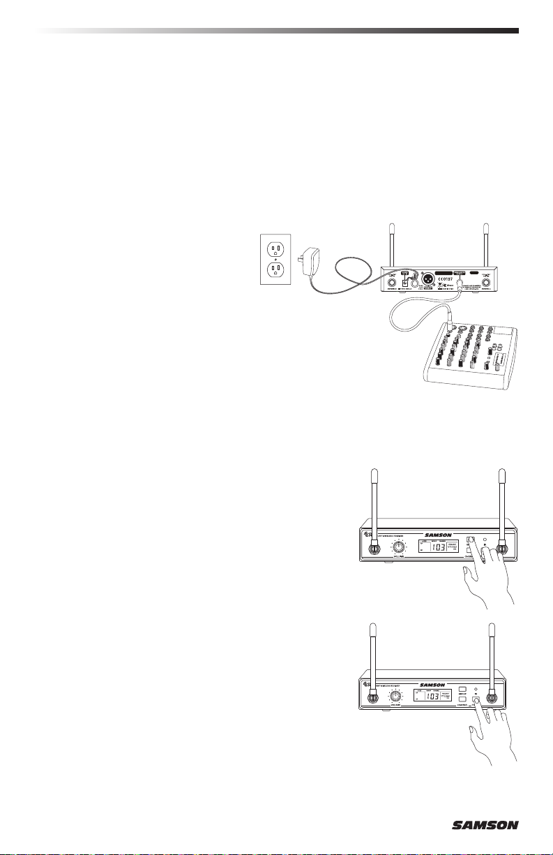
2. With the CR99 powered off,
connect the included power
adapter. Turn the CR99 on
momentarily to confirm that the
unit is receiving power. Then turn
the CR99 power off.
3. With your amplifier or mixer off
and volume control all the way
down, connect the CR99 receiver
output jack to the mic or line
level input of a mixer or amplifier
using the balanced XLR output or
unbalanced ¼” line level output.
Turn the Level knob on the CR99
completely counterclockwise, then
turn its power on.
ENGLISHFRANÇAISDEUTSCHEESPAÑOLITALIANO
4. Press and hold the GROUP button on the front of
the CR99 receiver to scan for an available channel
within the selected group.
5. Press and hold the CR99 CHANNEL button
to execute an IR Set which synchronizes the
transmitter to the same channel as the receiver via
infrared transmission.
AirLine ATX Wireless System 7

Quick Start
6. Position the ATX transmitter about 6-12” (15-
30 cm) from the front of the CR99 with the
transmitter’s IR window facing the IR transmitter
on the front panel of the CR99 receiver.
7. Make sure the ATX Headset transmitter is fully
charged (see section Charging the ATX Transmitter)
Turn on the power to the transmitter by pressing
and holding the Power button for 3 seconds; the
indicator LED will light yellow when the button is
pressed and turns green when released and the ATX
is powered on.
8. When the transmission is complete, the CR99
will receive RF signal and the tone key from the
transmitter. The RF meter on the CR99 will light
indicating that it is receiving wireless signal from
the transmitter.
Note: The ATX will only accept infrared
transmission from the receiver for the first 10
seconds after the ATX is powered on. If you need
to change the operating channel, the ATX must be
first powered off, then powered on again to receive
the new channel.
9. Turn on your connected amplifier or mixer, but keep
the volume all the way down. Set the Volume knob
on the CR99 fully clockwise (to its “10” setting).
This is unity gain.
10. Plug the microphone into the ATX transmitter.
Speak, sing or play your instrument into the microphone at normal performance
level. Slowly raise the volume of your amplifier or mixer until the desired level is
reached.
11. Walk around the performance area to ensure the coverage is consistent throughout.
If you find the system has noticeable dropouts, reduced overall working range, or
unexpected noise bursts, change the operating channel of the system using the
steps above.
When using multiple systems, each system must be set to a different operating channel. Set
all additional transmitters and receivers to the same Group in order to maximize the number
of compatible channels. Perform a channel scan for each transmitter to select the optimal
channel.
8

Charging the ATX Transmitter
1. Snap in place the appropriate mains connector plug into the adapter.
2. Insert the magnetic power cable to the included USB AC plug (or any 5-volt DC
adapter that has a USB port). Insert the AC plug into an electrical outlet.
3. Place the ATX transmitter on a flat surface.
4. Attach the magnetic connector to the gold contact power port on the bottom of the
ATX transmitter. The cable attaches to the port magnetically.
The magnetic connector is keyed so it will only connect in one direction.
Note: Transmission is disabled during charging.
5. Look at the indicator light on the ATX transmitter to determine when the transmitter
has finished charging. When the light is flashing red, the ATX is charging. When the
red light stops flashing it indicates that the ATX is fully charged.
6. Disconnect the magnetic power cable from the ATX when the unit is fully charged.
If you notice your ATX battery life is becoming shorter after a full charge, you can order
a user replaceable battery from your local Samson distributer.
ENGLISHFRANÇAISDEUTSCHEESPAÑOLITALIANO
Getting the most out of the rechargeable battery:
• Completely charge the batteries before first use
• Fully charge the battery before it will be used.
• After the battery is charged, unplug the charger from the outlet or
remove the battery from the charger.
• The optimal temperature range for using and storing the battery is
50°F - 86°F (30°C - 50°C). The battery performance and operation
may decrease in temperatures below 50°F (30°C).
A warning that batteries (battery pack or batteries installed) shall not be exposed to
excessive heat such as sunshine, fire or the like.
CAUTION: Danger of explosion if battery is incorrectly replaced. Replace only with the
same or equivalent type. Attention should be drawn to the environmental aspects of
battery disposal
AirLine ATX Wireless System 9
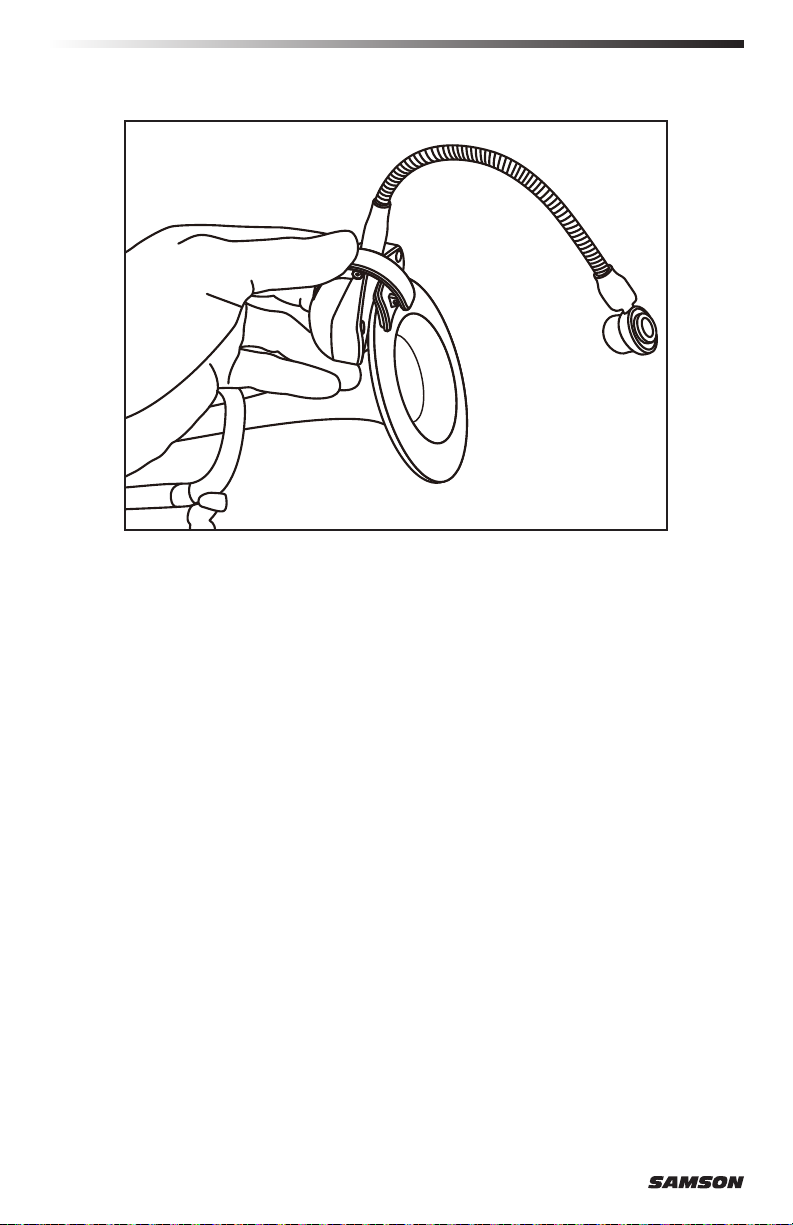
Positioning the HM60 Wind Instrument Mic
When positioning the HM60 wind instrument microphone, there are some general rules
that you should follow. Always position the microphone as close to the sound source as
possible. This is easy with the HM60 since the integrated gooseneck guarantees the mic
element is close to the source. Also, keep in mind that in order to minimize feedback
problems you want to position the microphone, (and if necessary yourself), behind the
main PA speakers. Be aware of a phenomenon called the proximity effect, which causes
a noticeable increase in low frequencies (bass response) when a microphone is close
to the audio source. This means that by making slight adjustments to the distance of
the mic element, you can get a change in the tonal quality of your sound. Keep in mind
that your sound is as personal as your playing style, therefore, you may find changing
the microphone position gets you just the sound you looking for. As with everything,
experience is the best teacher, so plug in and turn up and listen.
Here are some starting points to help you along the way.
Saxophone – Use the built-in clip to attach the ATX transmitter to the bell of the
instrument and position the HM60 mic about 1”–2”from the center of the bell. You can
move the mic out a little to get some extra edginess, or closer for some extra warmth.
Trumpet – Use the built-in clip to attach the ATX transmitter to the bottom of the bell
on the instrument. Aim the HM60 microphone towards the center of the bell, but since
the trumpet is capable of producing some of the highest SPL levels, start with the mic
element positioned away from the bell. Try bringing the microphone element in closer to
the bell for better isolation and more low frequency response.
Trombone – Attach the ATX clip to the bottom of the bell and position the HM60
microphone directly into the center. In this position you will get the maximum isolation
with full frequency response.
10

ATX Headset Transmitter Callouts
8
5 6
1
4
2
1. Power/Mute Button - Press and hold for 3 seconds to turn the unit on or off. A quick
press and release will mute or unmute the transmitter when the transmitter is on.
2. Status Indicator - This LED displays the operation mode, low battery and recharge
status of the transmitter. The chart below defines the LED colors for each function.
3. Volume +/– Buttons - Press and hold either Volume button to adjust the volume.
Pressing the + or – button increases or decrease the level by one step with each
push of the button. There is a total 9 volume levels. The Status Indicator light will
flash faster for each increased step and slower for each decrease.
4. IR Lens - This window is used to capture the infrared signal sent from the receiver
during the IR SET to channelize the transmitter. The IR Lens is only active for the
first 10 seconds when the transmitter is powered on.
5. Charging Connector - Connect the supplied magnetic charging cable to this sealed,
gold contact charging connector to recharge the internal Lithium Ion battery. The
ATX can be recharged by connecting the cable to a USB connector on a computer
USB port, or any 5-volt DC adapter that has a USB output.
NOTE: The included adapter will charge the ATX faster than a computer USB port.
6. Input Connector - Connect the input device via the mini-XLR connector. The ATX is
supplied with either a lavalier, headset or instrument microphone.
7. Spring Clip - Use this clip to fasten the ATX transmitter to a belt, waist band or
instrument bell.
3
GREEN Normal Operation
AMBER Mute
Flashing RED
RED Fully Charged
Low Battery
Charging
7
ENGLISHFRANÇAISDEUTSCHEESPAÑOLITALIANO
AirLine ATX Wireless System 11
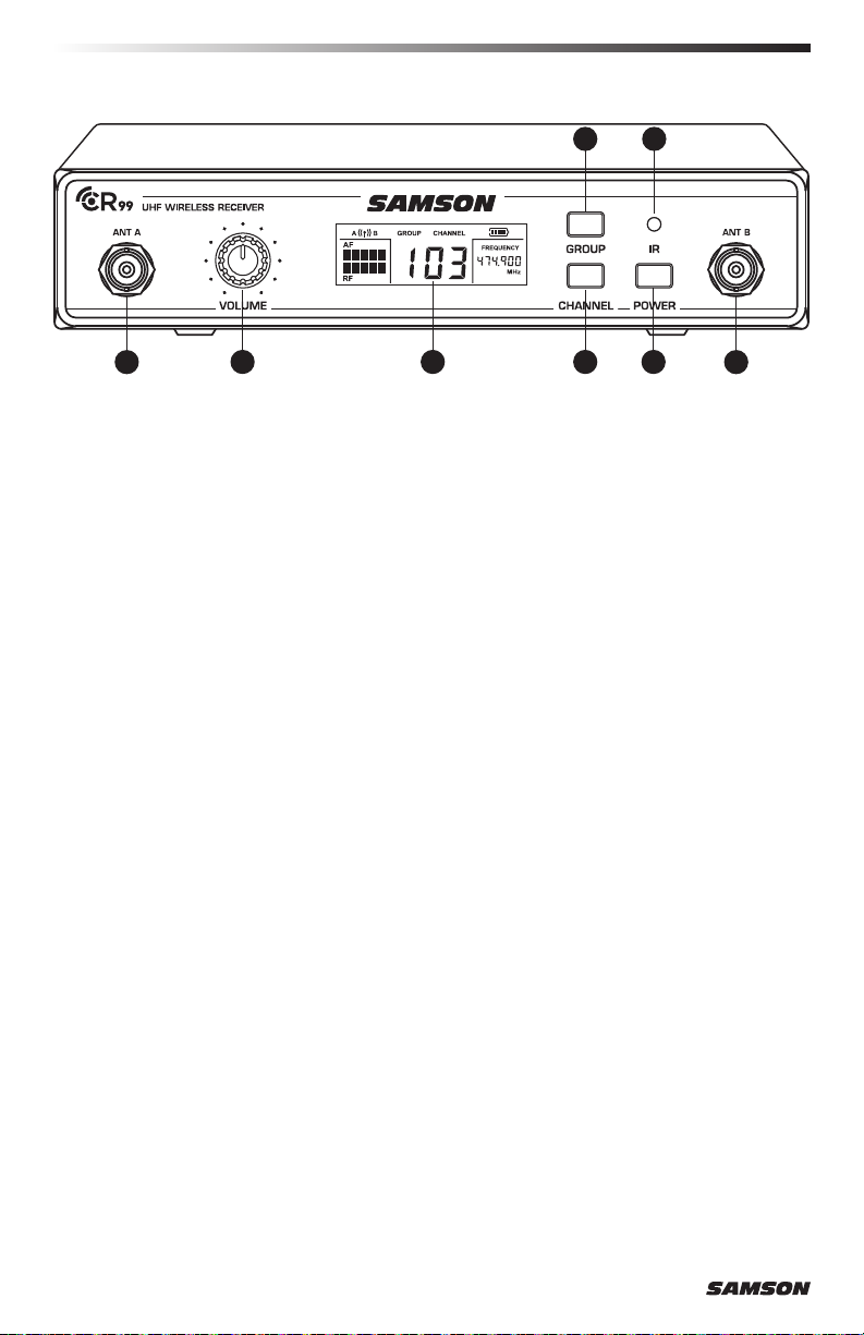
CR99 Receiver - Front Callouts
4
1 2 3
1. Antenna Jacks - The front BNC antenna jacks allow full rotation for optimum place-
ment. In normal operation, both antennas should be placed in a vertical position.
2. VOLUME Control - This knob sets the level of the audio signal being output through
both the balanced and unbalanced output jacks on the rear panel. Reference level
is obtained when the knob is turned fully clockwise (to its “10” setting).
3. LCD Display - Displays transmitter and receiver settings.
4. GROUP Button - Press and release button to cycle through the available groups. Press
and hold button to scan for available channels within the selected group.
5. CHANNEL Button - Press and release to cycle through available channels within a
group. Press and hold button to enter IR Set which is used to set the operating
channel of the transmitter.
6. POWER Button - Press and hold to turn the CR99 power on and off.
7. IR Transmitter - During “IR SET” an infrared light is used to set the transmitter
channel.
5 6
7
1
12
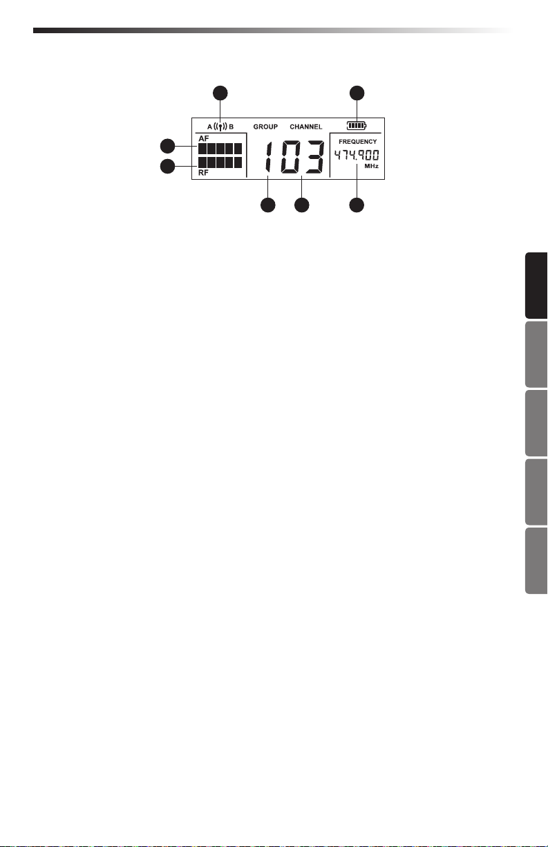
Receiver Display
D
F
G
A
B C
A. Group - Displays the selected group
B. Channel - Displays the selected channel
C. Frequency - Indicates the operating frequency of the selected Group and Channel.
D. Antenna Indicator - Indicates the active antenna (A or B).
E. Transmitter Battery Level - Indicates the battery level of the transmitter.
F. Audio Meter - Indicates the strength of the incoming audio signal.
G. RF Signal Meter - Indicates the strength of the incoming radio signal.
E
ENGLISHFRANÇAISDEUTSCHEESPAÑOLITALIANO
AirLine ATX Wireless System 13

1 12 3 4
CR99 Receiver - Rear Callouts
1. Antenna Jacks - The rear BNC antenna jacks allow full rotation for optimum placement.
In normal operation, both antennas should be placed in a vertical position.
2. DC Input - Connect the supplied power adapter here, using the strain relief as shown
in the illustration below. WARNING: Do not substitute any other kind of power
adapter. Doing so can cause severe damage to the CR99 and will void your warranty.
3. BALANCED OUTPUT - Use this electronically balanced low impedance (600 Ohm)
XLR jack when connecting the CR99 to professional (+4dBu) audio equipment. Pin
wiring is as follows: Pin 1 ground, Pin 2 high (hot), and Pin 3 low (cold).
4. UNBALANCED OUTPUT - Use this unbalanced high impedance (5K Ohm) ¼" jack
when connecting the CR99 to consumer (-10dBV) audio equipment. Wiring is as
follows: tip hot, sleeve ground.
Using the strain relief: Gather up a loop of wire and pass it
through the strain relief, then pass the adapter plug through
the loop in order to create a knot.
14
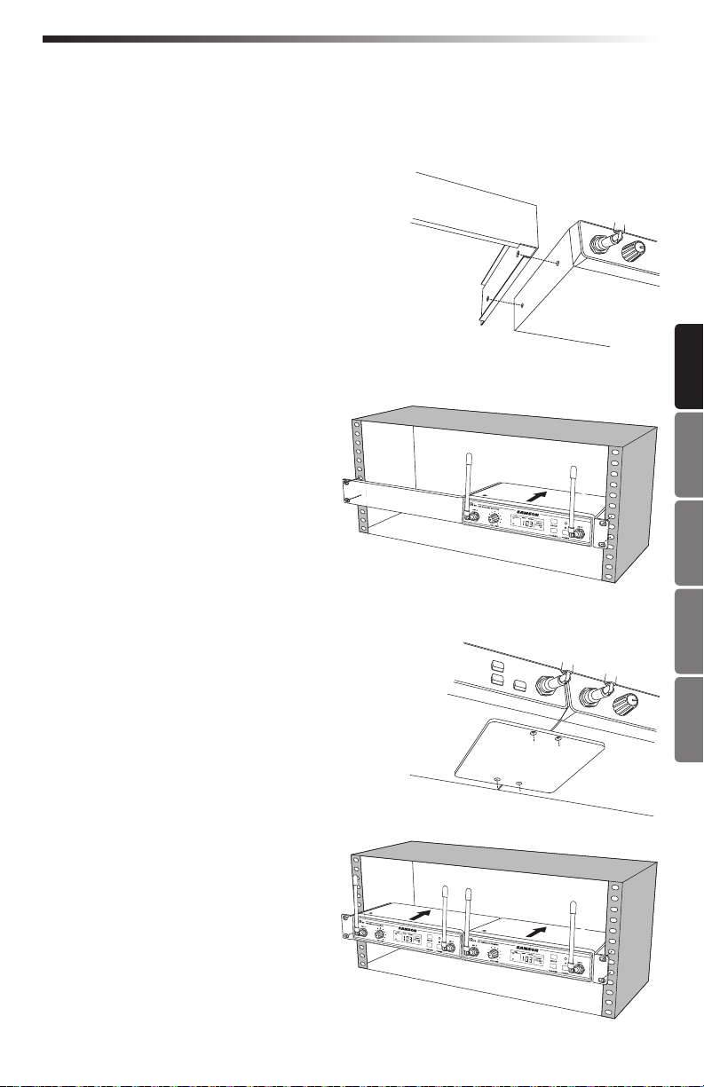
Rack Mounting
The CR99 receiver can be installed into a standard 19” rack for transport or permanent
installation using the included rack ears. Follow the simple steps below to mount the
CR99:
Attach the included rack ears by screwing each
rack ear into either side of the CR99.
Position the CR99 receiver into an available rack space and slide in until the
rack ears are touching the rails of the
rack case and are aligned with the rack
rail holes.
Mount the receiver into the rack using
the appropriate size rack screws (not
included). To ensure equal tension and
balance when installing the receiver,
you should secure screws in a crisscross
pattern of opposite corners: top left ->
bottom right -> top right -> bottom left.
In order to mount two CR99 receivers in one rack
space, the system includes a center connection
piece. Screw the center connection piece into
bottom of each receiver and attach the short rack
ears to each receiver.
ENGLISHFRANÇAISDEUTSCHEESPAÑOLITALIANO
Mount the receivers into the rack using
the crisscross pattern described above.
AirLine ATX Wireless System 15

Channel Plans
Group K 470–494MHz
Channel
Group 00 01 02 03 04 05 06 07
0 473.050 474.425 474.900 480.475 484.075 486.975 487.975 492.425
1 470.125 471.500 471.975 477.550 481.150 484.050 485.050 489.500
2 470.525 471.900 472.375 477.950 481.550 484.450 485.450 489.900
3 471.075 472.450 472.925 478.500 482.100 485.000 486.000 490.450
4 471.475 472.850 473.325 478.900 482.500 485.400 486.400 490.850
5 472.025 473.400 473.875 479.450 483.050 485.950 486.950 491.400
6 472.425 473.800 474.275 479.850 483.450 486.350 487.350 491.800
7 473.375 474.750 475.225 480.800 484.400 487.300 488.300 492.750
8 473.925 475.300 475.775 481.350 484.950 487.850 488.850 493.300
9 474.325 475.700 476.175 481.750 485.350 488.250 489.250 493.700
Group D** 542–566MHz
Channel
Group 00 01 02 03 04 05 06 07
0 545.050 546.425 546.900 552.475 556.075 558.975 559.975 564.425
1 542.125 543.500 543.975 549.550 553.150 556.050 557.050 561.500
2 542.525 543.900 544.375 549.950 553.550 556.450 557.450 561.900
3 543.075 544.450 544.925 550.500 554.100 557.000 558.000 562.450
4 543.475 544.850 545.325 550.900 554.500 557.400 558.400 562.850
5 544.025 545.400 545.875 551.450 555.050 557.950 558.950 563.400
6 544.425 545.800 546.275 551.850 555.450 558.350 559.350 563.800
7 545.375 546.750 547.225 552.800 556.400 559.300 560.300 564.750
8 545.925 547.300 547.775 553.350 556.950 559.850 560.850 565.300
9 546.325 547.700 548.175 553.750 557.350 560.250 561.250 565.700
Group G* 863–865MHz
Channel
Group 00 01 02 03 04 05 06 07
0 863.050 863.550 863.750 864.050 864.250 864.550 864.750 864.950
1 863.100 863.600 863.800 864.100 864.300 864.600 864.800 863.300
2 863.150 863.650 863.850 864.150 864.350 864.650 864.850 863.350
3 863.200 863.700 863.900 864.200 864.400 864.700 864.900 863.400
* Not for use in the USA and Canada.
** Not for use in the EU.
For questions regarding available channels in your area contact your local Samson distributor.
16

Specifications
System
Working Range 300' (100m) line of sight
Audio Frequency Response 50 Hz - 15 kHz
T.H.D. (Overall) <1% (@AF 1 kHz, RF 46 dBu)
Dynamic Range >100 dB A-weighted
Signal to Noise >95 dB
Operating Temperature –10°C (14°F) to +60°C (+140°F)
Tone Key Frequency 32.768 kHz
ATX Microphone Transmitter
Input Connector Mini-XLR (P3)
Input Impedance 3kΩ
Input Gain Range 20dB
RF Power 10mW EIRP
Power Requirements 3.6V 500mAh
Lithium Ion rechargeable battery
Battery Life 6 hours
Dimensions (LxWxH) 5.9” x 6.7” x 3.9”
150mm x 170mm x 100mm
Weight 0.13lb / 60g
CR99 Receiver
Audio Output Level - Unbalanced +14 dBu
Audio Output Level - Balanced +9 dBu
Audio Output Impedance - Unbalanced 810 Ohms
Audio Output Impedance - Balanced 240 Ohms
Sensitivity -100 dBm / 30 dB sinad
Image Rejection >50 dB
Operating Voltage 15 VDC 200mA
Dimensions (LxWxH) 7.87” x 5.9” x 1.6”
200mm x 150mm x 42mm
Weight 2.08lb / 0.946kg
ENGLISHFRANÇAISDEUTSCHEESPAÑOLITALIANO
At Samson, we are continually improving our products, therefore specifications and
images are subject to change without notice.
AirLine ATX Wireless System 17

Informations de sécurité importantes
RISQUE D’ÉLECTROCUTION !
NE PAS OUVRIR !
ATTENTION
Cet éclair avec un symbole
représentant une flèche dans
un triangle équilatéral est
destiné à alerter l’utilisateur
de la présence de «tension
dangereuse» non isolée à
l’intérieur du produit qui
peut être d’une importance
suffisante pour constituer un
risque de choc électrique.
ATTENTION: POUR RÉDUIRE LE RISQUE D’ÉLECTROCUTION, NE PAS OUVRIR LE
CAPOT (OU LA FACE ARRIÈRE). NE CONTIENT AUCUNE PIÈCE QUE L’UTILISATEUR
PEUT ENTRETENIR. CONFIER L’ENTRETIEN A UN TECHNICIEN QUALIFIÉ.
AVERTISSEMENT
POUR ÉVITER UN INCENDIE OU UNE ÉLECTROCUTION. NE PAS UTILISER CETTE
FICHE AVEC UNE RALLONGE OU TOUTE AUTRE PRISE, SAUF SI LES BROCHES
PEUVENT ÊTRE ENTIÈREMENT ENFONCÉES POUR ÉVITER QU’ELLES NE SOIENT
EXPOSÉES. POUR ÉVITER UN INCENDIE OU UNE ÉLECTROCUTION. NE PAS EXPOSER CET APPAREIL A LA PLUIE NI A L’HUMIDITÉ. POUR ÉVITER TOUT RISQUE
D’ELECTROCUTION, BIEN INSÉRER LA FICHE SECTEUR, CORRECTEMENT ET
ENTIÈREMENT.
Pour mettre ce produit au rebut, ne le mélangez pas aux ordures ménagères. Il
existe un système de collecte séparée pour les produits électroniques usagés,
conformément à la législation qui prévoit le traitement, la récupération et le
recyclage corrects.
Les ménages dans les 28 états membres de l’UE, en Suisse et en Norvège
peuvent mettre au rebut leurs produits électroniques usagés gratuitement auprès
d’installations de collecte agréées ou auprès d’un détaillant (si vous achetez un produit
neuf similaire).
Pour les pays non mentionnés ci-dessus, veuillez contacter les autorités locales pour
connaitre la méthode de traitement appropriée.
Ce faisant, vous vous assurerez que votre produit subit le traitement, la récupération
et le recyclage nécessaires et éviterez ainsi les effets négatifs potentiels sur
l’environnement et la santé humaine.
Le point d’exclamation dans
un triangle équilatéral est
destiné à alerter l’utilisateur
de la présence d’importantes
instructions de fonctionnement
et d’entretien dans la documentation accompagnant l’appareil.
18

Informations de sécurité importantes
1. Lisez ces instructions.
2. Conservez ces instructions.
3. Respectez tous les avertissements.
4. Suivez toutes les instructions.
5. N’utilisez pas cet appareil à proximité
d’une source d’eau.
6. Nettoyer uniquement avec un chiffon
sec.
7. Ne pas obstruer les ouvertures de
ventilation. Installer conformément
aux instructions du fabricant.
8. Ne pas installer près de sources de
chaleur telles que des radiateurs, des
diffuseurs d’air chaud, des fours, des
poêles ou autres appareils (y compris
les amplificateurs) émettant de la
chaleur.
9. Ne pas utiliser la fiche polarisée ou
de terre à un autre usage que celui
prévu. Une fiche polarisée comporte
deux broches, l’une plus large que
l’autre. Une fiche de terre comporte
deux broches et une troisième de
mise à la terre. La broche large,
ou troisième broche, assure votre
sécurité. Si la fiche fournie de
correspond pas à votre fiche murale,
consultez un électricien pour faire
remplacer la fiche murale obsolète.
10. Faites en sorte que le cordon ne soit
pas piétiné ni pincé, en particulier
au niveau des fiches, des prises de
courant, ou au point de sortie de
l’appareil.
11. Utiliser uniquement des fixations/
accessoires spécifiés par le fabricant.
12. Utilisez-le uniquement avec le chariot,
le trépied, un support ou une table
spécifiés par le fabricant ou vendus
avec l’appareil. Lors de l’utilisation
d’un chariot, soyez prudent lors du
déplacement de l’ensemble chariot/
appareil pour éviter des blessures
dues au renversement.
13. Débranchez l’appareil pendant les
orages ou lorsqu’il reste inutilisé
pendant une période prolongée.
14. Confiez toutes les opérations
d’entretien à un technicien qualifié.
Une réparation est nécessaire si
l’appareil a été endommagé d’une
façon quelconque, par exemple
si le cordon d’alimentation ou la
fiche sont endommagés, en cas de
dommages dus au renversement de
liquides ou de chutes d’objets dans
l’appareil, d’une exposition à la pluie
ou à l’humidité, ou si l’appareil ne
fonctionne pas normalement ou est
tombé.
15. Cet appareil ne doit pas être exposé
à des gouttes ni à des éclaboussures
et aucun objet rempli de liquide,
comme un vase, ne doit être placé sur
l’appareil.
16. Attention, afin d’éviter tout risque
d’électrocution, bien insérer la fiche
secteur correctement et entièrement.
17. Veiller à assurer une ventilation
correcte autour de l’unité.
18. L’adaptateur secteur direct est utilisé
comme dispositif de déconnexion,
lequel doit rester facilement
accessible.
19. Les piles (batterie ou piles installées)
ne doivent pas être exposées à une
chaleur excessive comme les rayons
du soleil, le feu ou autre.
ENGLISHFRANÇAISDEUTSCHEESPAÑOLITALIANO
Système sans fil ATX AirLine 19
Informations de sécurité importantes
Règles et règlements de la FCC
Les récepteurs sans fil Samson sont certifiés en vertu des règles de la partie 15 de la
FCC et les émetteurs sont certifiés en vertu des règles de la partie 74 de la FCC.
La concession de licence des équipements Samson relève de la responsabilité
de l’utilisateur et dépend de la classification, de l’application et de la fréquence
sélectionnées par l’utilisateur.
Cet appareil est conforme à la partie 15 de la FCC Classe B et à la norme RSS-210
d’Industry & Science Canada.
Son fonctionnement est soumis aux deux conditions suivantes:
(1) cet appareil ne doit pas causer d’interférences nuisibles et
(2) cet appareil doit accepter toute interférence reçue, notamment celles pouvant
entraîner un dysfonctionnement. Adapté à un usage résidentiel ou commercial.
REMARQUE: Cet équipement a été testé et jugé conforme aux limites d’un appareil
numérique de classe B, conformément à la partie15 des règles de la FCC. Ces limites
sont conçues pour fournir une protection raisonnable contre les interférences nuisibles
dans une installation résidentielle. Cet équipement génère, utilise et peut émettre
de l’énergie à radiofréquences et, s’il n’est pas installé et utilisé conformément aux
instructions, peut causer des interférences nuisibles aux communications radio.
Cependant, il n’y a aucune garantie que des interférences ne se produiront pas dans
une installation particulière. Si cet équipement provoque des interférences nuisibles à
la réception de la radio ou de la télévision, ce qui peut être déterminé en éteignant et
en rallumant l’appareil, l’utilisateur est invité à essayer de corriger les interférences en
prenant une ou plusieurs des mesures suivantes:
• Modifier l’orientation ou l’emplacement de l’antenne de réception.
• Augmenter la distance entre l’équipement et le récepteur.
• Brancher l’appareil dans une prise sur un circuit différent de celui auquel le
récepteur est connecté.
• Demander de l’aide au revendeur ou à un technicien radio/TV expérimenté.
AVERTISSEMENT: Tout changement ou modification n’ayant pas été expressément
approuvé(e) par la partie responsable de la conformité pourrait annuler l’autorité de
l’utilisateur à utiliser ce dispositif.
Cet équipement est destiné à être utilisé dans des applications de microphones sans fil.
L’équipement est destiné à la vente dans: AT, BE, CH, CY, CZ*, DK, EE, FI*, FR*, DE*,
GR*, HU, IE, IS, IT, LV, LT*, LU, MT*, NL, NO*, PL* PT, RO, SK, SI, ES, SE, UK
*Soumis à une licence. Veuillez contacter les autorités nationales relatives à la fréquence pour obtenir des informations sur l’utilisation légale disponible dans votre
région. Tout changement ou modification non expressément approuvé par Samson
Technologies Corp. pourrait annuler votre droit d’utiliser l’équipement.
Par la présente, Samson Technologies Corp., déclare que ces appareils CR99 et AG8
sont conformes aux exigences essentielles et autres dispositions pertinentes de la directive 2014/53/CE. Cette déclaration de conformité peut être consultée à l’adresse:
http://www.samsontech.com/site_media/support/manuals/AirLineATX_DOC.pdf
20

Introduction
Merci d’avoir acheté le système sans fil AirLine ATX de Samson. Le système AirLine ATX est
l’émetteur micro à fréquence agile le plus compact du marché. Solution idéale pour l’artiste
actif qui a besoin d’un système de sonorisation fiable et performant sans les inconvénients
d’un émetteur volumineux.
Équipé d’un récepteur CR99 intégré, doté d’un grand écran LCD rétro-éclairé, très simple
d’utilisation grâce à la sélection de canaux par recherche automatique, et d’un ensemble
infrarouge pour la synchronisation du canal de l’émetteur et du récepteur, le modèle AirLine
ATX est simple et facile à installer et à utiliser. Le système AirLine ATX assure un son
clair et sans interruption, grâce à une conception True Diversity RF dotée d’une tonalité
pilote et d’une fonction auto-mute. Cette configuration permet une distance maximale de
fonctionnement ainsi que l’élimination de tout bruit de fond lorsque l’émetteur est hors de
portée ou hors tension.
Le système AirLine ATX se décline en trois configurations. Le système serre-tête AHX peut
être associé au choix, au microphone serre-tête DE5 ou Qe, au système ALX Lavalier avec le
microphone LM8 lavalier, et au système d’instrument à vent AWX avec le microphone pour
instruments à vent HM60. Le système AirLine ATX est livré avec un kit de montage en rack
standard de 19» pour les installations permanentes ou le transport dans un rack mobile.
Ces pages vous présentent une description détaillée des caractéristiques du système sans fil
AirLine ATX ainsi que des instructions détaillées d’installation et d’utilisation. Si vous avez
acheté votre système sans fil en dehors des États-Unis, une carte d’inscription vous est fournie.
Vous trouverez également des informations sur la façon d’enregistrer votre produit en ligne
afin de bénéficier du support technique en ligne, et pour que nous puissions vous envoyer des
informations à jour à ce sujet et d’autres produits Samson à l’avenir. De même, assurez-vous de
consulter notre site Web www.samsontech.com pour en savoir plus sur notre ligne complète de
produits.
Nous vous recommandons de conserver les informations suivantes pour référence, ainsi que
la copie de votre facture:
Numéro de série du récepteur: _________________________________________
ENGLISHFRANÇAISDEUTSCHEESPAÑOLITALIANO
Numéro de série de l’émetteur: ______________________________________
Date d’achat: ______________________________________________
Pour toute question ou commentaire sur le système de microphone sans fil AirLine ATX ou sur
tout autre produit Samson, n’hésitez pas à nous contacter par email à support@samsontech.com.
En l’entretenant et en l’utilisant correctement, vous bénéficierez de votre système sans fil AirLine
ATX pendant de nombreuses années. Si votre système sans fil AirLine ATX doit être réparé, vous
devez demander un numéro RA (Autorisation de retour, Return Authorization) avant d’expédier
votre appareil à Samson. Sans ce numéro, l’unité ne sera pas acceptée. Veuillez visiter le site
Web www.samsontech.com/ra afin d’obtenir un numéro RA avant d’expédier votre appareil. Veuillez
conserver les matériaux d’emballage d’origine et, si possible, retourner l’appareil dans son carton
d’origine. Si vous avez acheté votre système sans fil AirLine ATX en dehors des États-Unis,
contactez votre distributeur local pour en savoir plus sur la garantie et les services d’entretien.
Système sans fil ATX AirLine 21
Démarrage rapide
Pour que votre système sans fil fonctionne correctement, le récepteur et l’émetteur doivent
être réglés sur le même canal. Suivez cette procédure de base pour la mise en place et
l’utilisation de votre système sans fil AirLine ATX:
1. Placez le récepteur CR99 à l’endroit où il sera utilisé, et déployez les antennes
verticalement. La règle générale est de maintenir la «ligne de vue» entre le récepteur et
l’émetteur afin que la personne utilisant ou portant l’émetteur puisse voir le récepteur.
2. Alors que le système CR99 est
hors tension, branchez l’adaptateur
secteur fourni. Allumez le système
CR99 momentanément pour
confirmer que l’appareil est sous
tension. Puis éteignez le système
CR99.
3. Avec l’amplificateur ou le mixeur
hors tension et la commande de
volume au niveau le plus faible,
reliez la prise de sortie du récepteur
CR99 à l’entrée micro ou à l’entrée
de niveau de ligne d’un mixeur ou
d’un amplificateur via la sortie XLR
symétrique ou la sortie de niveau de
ligne asymétrique d’¼” (0,63cm).
Tournez le bouton du niveau à
fond dans le sens antihoraire sur
le système CR99, puis mettez ce
dernier sous tension.
4. Appuyez et maintenez la touche GROUP enfoncée sur
la face avant du récepteur CR99 pour rechercher un
canal disponible dans le groupe sélectionné.
5. Appuyez et maintenez enfoncée la touche CR99
CHANNEL pour exécuter le réglage IR Set qui
synchronise l’émetteur sur le même canal que le
récepteur, via une transmission infrarouge.
22

Démarrage rapide
6. Positionnez l’émetteur ATX à environ 6-12” (15-
30cm) de l’avant du CR99 avec la lentille infrarouge
de l’émetteur face à l’émetteur IR sur le panneau
avant du récepteur CR99.
7. Assurez-vous que l’émetteur du micro-casque AH8
est complètement chargé (voir la section Chargement
de l’émetteur ATX) Mettez l’émetteur sous tension en
appuyant sur le bouton d’alimentation pendant 3
secondes; le voyant s’allume en jaune clair lorsque
vous appuyez sur le bouton et passe au vert lorsque
vous le relâchez et l’ATX est alors allumé.
8. Lorsque la transmission est terminée, le CR99 reçoit
le signal RF et la clé de tonalité depuis l’émetteur. Le
compteur RF du CR99 s’allume alors pour indiquer
qu’il reçoit le signal sans fil de l’émetteur.
Remarque: L’unité ATX n’accepte la transmission
infrarouge du récepteur que pendant les 10 premières
secondes après sa mise sous tension. Si vous devez
changer le canal d’exploitation, éteignez, puis
rallumez le boîtier ATX pour recevoir le nouveau canal.
9. Allumez alors l’amplificateur connecté ou une console
de mixage, mais maintenez le volume au plus bas.
Tournez le bouton du volume du CR99 à fond dans le
sens horaire (à son réglage «10»). Il s’agit du gain de
l’unité.
ENGLISHFRANÇAISDEUTSCHEESPAÑOLITALIANO
10. Branchez le microphone sur l’émetteur ATX. Parlez,
chantez ou jouez de votre instrument dans le
microphone à un niveau sonore normal. Augmentez
lentement le volume de l’amplificateur ou de la console de mixage, jusqu’à ce que vous
ayez atteint le niveau souhaité.
11. Faites le tour de la salle de concert pour vous assurer que la couverture est cohérente
partout. Si vous constatez que le système présente des pertes notables, une diminution
de l’amplitude de fonctionnement en général, ou des salves de bruit inattendues,
modifiez le canal de fonctionnement du système en suivant les étapes ci-dessus.
En cas d’utilisation de plusieurs systèmes, chaque système doit être réglé sur un canal d’exploitation différent. Réglez tous les émetteurs et récepteurs supplémentaires sur le même groupe afin
de maximiser le nombre de canaux compatibles. Effectuez une recherche de canal pour chaque
émetteur afin de sélectionner le canal optimal.
Système sans fil ATX AirLine 23

Chargement de l’émetteur ATX
1. Enclenchez le connecteur approprié dans l’adaptateur.
2. Insérez le câble d’alimentation magnétique dans la prise secteur USB CA incluse (ou
tout autre adaptateur de 5volts CC équipé d’un port USB). Insérez la fiche secteur dans
une prise électrique.
3. Placez l’émetteur ATX sur une surface plane.
4. Raccordez le connecteur magnétique au port d’alimentation de contact doré sur le fond
de l’émetteur ATX. Le câble se connecte au port magnétiquement.
Le connecteur magnétique est conçu de telle manière qu’il ne se connecte que dans un
sens.
Remarque: la transmission est désactivée pendant le chargement.
5. Observez le voyant de l’émetteur ATX pour déterminer quand l’émetteur est entièrement
chargé. Lorsque le voyant clignote en rouge, l’ATX est en charge. Lorsque le voyant rouge
cesse de clignoter, cela signifie que le boîtier ATX est complètement chargé.
6. Débranchez le câble d’alimentation magnétique du boîtier ATX lorsque l’appareil est
complètement chargé.
Si vous remarquez que la durée de vie de la batterie du boîtier ATX est de plus en plus
courte après une charge complète, vous pouvez commander une batterie remplaçable par
l’utilisateur auprès de votre distributeur Samson local.
Tirer le meilleur parti de la batterie rechargeable:
• Chargez complètement les batteries avant la première utilisation
• Chargez complètement la batterie avant de l’utiliser.
• Une fois la batterie chargée, débranchez le chargeur de la prise ou retirez
la batterie du chargeur.
• La plage de température optimale d’utilisation et de stockage de la
batterie est de 50°F - 86 °F (30 °C - 50 °C). Les performances et le
fonctionnement de la batterie peuvent diminuer à des températures
inférieures à 50°F (30°C).
Avertissement: les piles (batterie ou piles installées) ne doivent pas être exposées à une
chaleur excessive comme les rayons du soleil, le feu ou autre.
ATTENTION: Risque d’explosion si la batterie n’est pas correctement remplacée. Remplacezla uniquement par une batterie de même type ou de type équivalent. Vous devez être attentif
aux aspects environnementaux de la mise au rebut des piles.
24
 Loading...