

Page 1
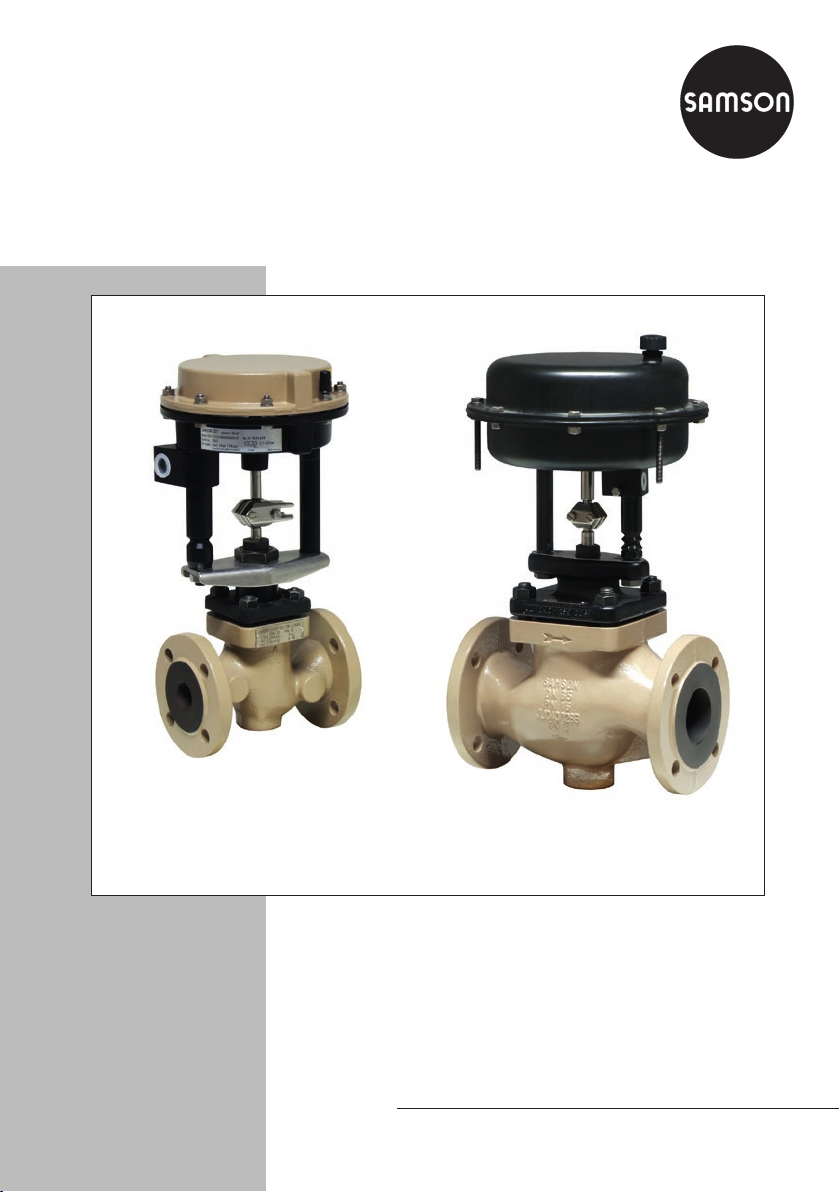
Type3371 Pneumatic Actuator
Actuator area: 120 and 350cm²
Translation of original instructions
Type3371 with 120cm² actuator area Type3371 with 350cm² actuator area
Mounting and
Operating Instructions
EB 8317 EN
Edition November 2016
Page 2
Note on these mounting and operating instructions
These mounting and operating instructions assist you in mounting and operating the device
safely. The instructions are binding for handling SAMSON devices.
Î For the safe and proper use of these instructions, read them carefully and keep them for
later reference.
Î If you have any questions about these instructions, contact SAMSON‘s After-sales Service
Department (aftersalesservice@samson.de).
The mounting and operating instructions for the devices are included in
the scope of delivery. The latest documentation is available on our website
(www.samson.de) > Product documentation. You can enter the document
number or type number in the [Find:] eld to look for a document.
Denition of signal words
!
DANGER
Hazardous situations which, if not avoided,
will result in death or serious injury
!
WARNING
Hazardous situations which, if not avoided,
could result in death or serious injury
2 EB 8317 EN
!
NOTICE
Property damage message or malfunction
Note
Additional information
Tip
Recommended action
Page 3

Contents
1 Safety instructions and measures ...................................................................5
1.1 Notes on possible severe personal injury .........................................................7
1.2 Notes on possible personal injury ...................................................................7
1.3 Notes on possible property damage ................................................................8
2 Markings on the device ...............................................................................10
2.1 Actuator nameplate ......................................................................................10
3 Design and principle of operation ................................................................12
3.1 Direction of action ........................................................................................12
3.2 Signal pressure routing .................................................................................12
3.3 Fail-safe action ............................................................................................15
3.3.1 Version with direction of action "actuator stem extends" (FA) ...........................15
3.3.2 Version with direction of action "actuator stem retracts" (FE) ............................15
3.4 Mounting types ............................................................................................15
3.5 Versions ......................................................................................................17
3.6 Technical data .............................................................................................17
4 Measures for preparation ............................................................................19
4.1 Unpacking ..................................................................................................19
4.2 Transporting and lifting ................................................................................19
4.2.1 Transporting ................................................................................................19
4.2.2 Lifting ..........................................................................................................19
4.3 Storage .......................................................................................................19
4.4 Preparation for installation ............................................................................21
5 Mounting and start-up .................................................................................22
5.1 Mounting the actuator onto the valve .............................................................22
5.1.1 120cm² version ..........................................................................................24
5.1.2 350cm² version ..........................................................................................26
5.2 Changing the mounting type .........................................................................27
5.2.1 Changing the mounting type to mounting using rods (FormB to FormC) ..........27
5.2.2 Changing the mounting type to mounting using a crossbeam
(FormC to FormB) .......................................................................................28
5.3 Preloading the springs ..................................................................................28
EB 8317 EN 3
Page 4

Contents
5.3.1 Increasing the actuator thrust ........................................................................29
5.3.2 Adapting the travel range .............................................................................29
5.4 Additional ttings .........................................................................................30
6 Operation ...................................................................................................31
6.1 On/off service .............................................................................................31
6.2 Reversal of the direction of action ..................................................................31
6.2.1 120cm² version ..........................................................................................32
6.2.2 350cm² version ..........................................................................................34
6.3 Version with travel stop .................................................................................36
6.3.1 Bottom travel stop (minimum travel) ...............................................................36
6.3.2 Top travel stop (maximum travel) ...................................................................37
6.4 Version with handwheel ................................................................................37
6.4.1 Operating the handwheel of version with "stem extends" direction of action .....37
6.4.2 Operating the handwheel of version with "stem retracts" direction of action ......37
7 Servicing.....................................................................................................38
7.1 Replacing the diaphragm .............................................................................39
7.1.1 120cm² version ..........................................................................................39
7.1.2 350cm² version ..........................................................................................41
7.2 Preparation for return shipment .....................................................................44
7.3 Ordering spare parts and operating supplies .................................................44
8 Malfunctions ...............................................................................................45
9 Decommissioning and disassembly ..............................................................46
9.1 Decommissioning .........................................................................................46
9.2 Removing the actuator from the valve ............................................................46
9.2.1 120cm² version ..........................................................................................46
9.2.2 350cm² version ..........................................................................................47
9.3 Relieving the spring compression in the actuator .............................................47
9.4 Disposal ......................................................................................................47
10 Annex.........................................................................................................48
10.1 After-sales service ........................................................................................48
10.2 Spare parts .................................................................................................49
4 EB 8317 EN
Page 5

Safety instructions and measures
1 Safety instructions and measures
Intended use
The SAMSON Type3371 Actuator is designed for operating a mounted globe valve. In combination with the valve, the actuator is used to shut off the ow of liquids, gases or vapors in
the pipeline. The actuator is suitable for on/off service. The actuator can be used in processing and industrial plants.
The actuator is designed to operate under exactly dened conditions (e.g. thrust, travel).
Therefore, operators must ensure that the actuator is only used in applications that meet the
specications used for sizing the actuator at the ordering stage. In case operators intend to
use the actuator in other applications or conditions than specied, contact SAMSON.
SAMSON does not assume any liability for damage resulting from the failure to use the device for its intended purpose or for damage caused by external forces or any other external
factors.
Î Refer to the technical data and nameplate for limits and elds of application as well as
possible uses.
Reasonably foreseeable misuse
The actuator is not suitable for the following applications:
− Use outside the limits dened during sizing and in the technical data
− Use outside the limits dened by the accessories mounted on the actuator
Furthermore, the following activities do not comply with the intended use:
− Use of non-original spare parts
− Performing service and repair work not described in these instructions
Qualications of operating personnel
The actuator must be mounted, started up, serviced, and repaired by fully trained and qualied personnel only; the accepted industry codes and practices are to be observed. According to these mounting and operating instructions, trained personnel refers to individuals who
are able to judge the work they are assigned to and recognize possible hazards due to their
specialized training, their knowledge and experience as well as their knowledge of the applicable standards.
EB 8317 EN 5
Page 6

Safety instructions and measures
Personal protective equipment
We recommend wearing the following personal protective equipment when handling the
Type3371 Pneumatic Actuator:
− Protective gloves when mounting or removing the actuator
Î Check with the plant operator for details on further protective equipment.
Revisions and other modications
Revisions, conversions or other modications to the product are not authorized by SAMSON.
They are performed at the user's own risk and may lead to safety hazards, for example. Furthermore, the product may no longer meet the requirements for its intended use.
Safety devices
The Type3371 Actuator does not have any special safety equipment.
Warning against residual hazards
To avoid personal injury or property damage, plant operators and operating personnel must
prevent hazards that could be caused in the actuator by the process medium, the operating
pressure, the signal pressure or by moving parts by taking appropriate precautions. They
must observe all hazard statements, warning and caution notes in these mounting and operating instructions, especially for installation, start-up, and service work.
Responsibilities of the operator
The operator is responsible for proper operation and compliance with the safety regulations.
Operators are obliged to provide these mounting and operating instructions as well as the
referenced documents to the operating personnel and to instruct them in proper operation.
Furthermore, the operator must ensure that operating personnel or third persons are not exposed to any danger.
Responsibilities of operating personnel
Operating personnel must read and understand these mounting and operating instructions as
well as the referenced documents and observe the hazard statements, warning and caution
notes specied in them. Furthermore, the operating personnel must be familiar with the applicable health, safety and accident prevention regulations and comply with them.
6 EB 8317 EN
Page 7

Safety instructions and measures
Referenced standards and regulations
According to the ignition risk assessment performed in accordance with EN13463-1:2009,
section 5.2, the non-electrical actuators do not have their own potential ignition source even
in the rare incident of an operating fault. As a result, they do not fall within the scope of Directive 2014/34/EU.
Î For connection to the equipotential bonding system, observe the requirements specied in
section 6.4 of EN60079-14 (VDE0165 Part 1).
Referenced documentation
The following documents apply in addition to these mounting and operating instructions:
− Mounting and operating instructions for the mounted valve e.g. uEB8111 for
SAMSON Type3321 Valve
− Mounting and operating instructions for mounted valve accessories (positioner, solenoid
valve etc.)
− uAB0100 for tools, tightening torques, and lubricant
1.1 Notes on possible severe personal injury
!
DANGER
Risk of bursting in the actuator.
Actuators are pressurized. Improper opening can lead to actuator components bursting.
Î Before starting any work on the actuator, depressurize all plant sections con-
cerned and the actuator.
EB 8317 EN 7
Page 8

Safety instructions and measures
1.2 Notes on possible personal injury
!
WARNING
Crush hazard arising from moving parts.
The actuator contains moving parts (actuator stem), which can injure hands or ngers if
inserted into the actuator.
Î Do not insert hands or ngers into the yoke while the valve is in operation.
Î While working on the actuator, disconnect and lock the pneumatic air supply as well
as the control signal.
Risk of personal injury due to preloaded springs.
Actuators with preloaded springs are under tension. They can be identied by the long
bolts protruding from the bottom of the actuator.
Î Before starting any work on the actuator, relieve the compression from the preload-
ed springs (see section9.3).
Risk of personal injury when the actuator vents.
While the valve is operating, the actuator may vent when the valve opens or closes.
Î Install the control valve in such a way that the actuator does not vent at eye level.
Î Use suitable silencers and vent plugs.
Î Wear eye protection when working in close proximity to the control valve.
Damage to health relating to the REACH regulation.
If a SAMSON device contains a substance which is listed as being a substance of very
high concern on the candidate list of the REACH regulation, this circumstance is indicated on the SAMSON delivery note.
Î Information on safe use of the part affected, see
uhttp://www.samson.de/reach-en.html.
8 EB 8317 EN
Page 9

Safety instructions and measures
1.3 Notes on possible property damage
!
NOTICE
Risk of actuator damage due to excessively high or low tightening torques.
Observe the specied torques on tightening actuator components. Excessively tightened
torques lead to parts wearing out quicker. Parts that are not tightened far enough may
loosen.
Î Observe the specied tightening torques (uAB0100).
Risk of actuator damage due to the use of unsuitable tools.
Certain tools are required to work on the actuator.
Î Only use tools approved by SAMSON (uAB0100).
Risk of actuator damage due to the use of unsuitable lubricants.
The lubricants to be used depend on the actuator material. Unsuitable lubricants may
corrode and damage the valve surface.
Î Only use lubricants approved by SAMSON (uAB0100).
EB 8317 EN 9
Page 10
Markings on the device
SAMSON 3371
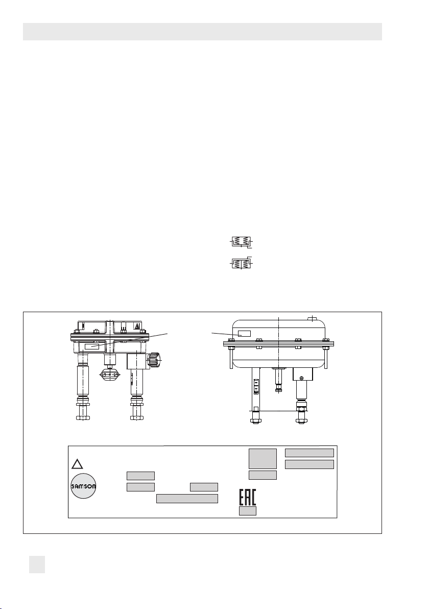
2 Markings on the device
2.1 Actuator nameplate
The nameplate is stuck on the diaphragm
casing (see Fig.1). The nameplate of the
Type3371 with 120cm² actuator area is located on the bottom diaphragm case. The
nameplate of the Type3371 with 350cm²
actuator area is located on the top diaphragm case.
Nameplate
It includes all details required to identify the
device (see Fig.2):
1 Type designation
2 Conguration ID
3 Serial number
4 Permissible supply pressure p
max
in
bar/psi
5 Bench range in bar
6 Bench range in psi
7 Operating travel in mm
8 Symbol indicating fail-safe action
Actuator stem extends (FA)
Actuator stem retracts (FE)
9 Date of manufacture (month and year)
Fig.1: Location of nameplate
5
6
!
See technical data for ambient temperature
Model
Var.-ID Serial no.
Air supply max.
SAMSON AG D-60314 Frankfurt Made in Germany
Fig.2: Example for nameplate
Pneumatic Actuator 120 cm²
1
2 3
4
8
7
9
10 EB 8317 EN
Page 11

EB 8317 EN 11
Page 12

Design and principle of operation
3 Design and principle of oper-
ation
The Type3371 Pneumatic Actuators have an
actuator area of either 120 or 350cm².
They are mainly used for attachment to Series V2001 Valves:
− Type 3321 Globe Valve
− Type3323 Three-way Valve
− Type3531 Globe Valve for Heat Transfer
Oil
− Type3535 Three-way Valve for Heat
Transfer Oil
Table1 provides an overview of the possible
combinations and how the actuator is
mounted on the valve.
The pneumatic actuators mainly consist of
two diaphragm cases, a diaphragm, and internal springs. The actuator is connected to
the valve bonnet using a rod-type yoke. The
stem connector clamps connect the actuator
stem with the plug stem of the valve.
The signal pressure p
p
· A at the diaphragm surface A, which is
st
opposed by the springs in the actuator. The
bench range is determined by the number of
springs used and their compression, taking
into account the rated travel. The travel is
proportional to the signal pressure p
creates the force F =
st
.
st
tion on the top diaphragm case. With direction of action "actuator stem extends", the
compressed air is applied to the signal pressure connection on the bottom diaphragm
case.
The actuator's direction of action can be reversed (see section6.2).
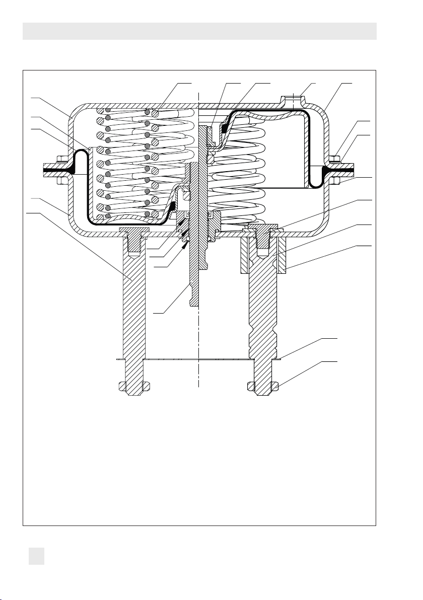
3.2 Signal pressure routing
120cm² version (see Fig.3)
In the "actuator stem extends" version, the
signal pressure is routed through the bottom
signal pressure connection (A35) to the bottom diaphragm chamber and moves the actuator stem (A3) upward opposing the
spring force.
In the "actuator stem retracts" version, the
signal pressure is routed through the top signal pressure connection to the top diaphragm chamber and moves the actuator
stem (A3) downward opposing the spring
force.
3.1 Direction of action
The direction of action is determined by how
the springs and diaphragm plate are arranged in the actuator. With direction of action "actuator stem retracts", the compressed
air is applied to the signal pressure connec-
12 EB 8317 EN
Page 13
Design and principle of operation
A31
•
A26
A10
A18
A13
A14
A11
A35
Mounting with crossbeam Mounting without crossbeam
A16
A2
•
•
•
•
A1
•
•
A3
•
A1 Vent plug
A2 Bottom diaphragm case
A3 Actuator stem
A10 Spring
A11 Rod
A12 Bushing
A13 Diaphragm plate
A14 Diaphragm plate
Fig.3: Functional diagram of Type3371 Actuator with 120cm² actuator area
•
A30
•
A17
•
A16 Top diaphragm case
A17 Crossbeam
A18 Diaphragm
A26 Collar nut
A30/
Stem connector clamps
A31
A35 Pneumatic connection
A72 Rod nut
•
A12
•
A72
EB 8317 EN 13
Page 14
Design and principle of operation
A61
A10
A1
S
A15
A51
A50
A25
A20
A21
A27
A1
A5
A4
A2
A33
A1 Top diaphragm case
A2 Bottom diaphragm case
A4 Diaphragm
A5 Diaphragm plate
A7 Actuator stem
A10 Spring
A15 Collar nut
A20 Hexagon bolt
•
•
•
•
•
A40
A42
A41
•
A7
A21 Hexagon nut
A25 Washer
A27 Compressor
A33 Rod
A40 Radial shaft seal
A41 Wiper ring
A42 Dry bearing
A50 Screw for rod (A51)
•
•
A60
A54
•
•
•
•
•
•
•
•
•
•
A51 Rod
A54 Rod nut
A60 Plate
A61 Pneumatic connection
S Signal pressure
connection (stem retracts)
Fig.4: Functional diagram of Type3371 Actuator with 350cm² actuator area
14 EB 8317 EN
Page 15

Design and principle of operation
350cm² version (see Fig.4)
In the "actuator stem extends" version, the
signal pressure is routed through the bottom
signal pressure connection (S) to the bottom
diaphragm chamber and moves the actuator
stem (A7) upward opposing the spring force.
In the "actuator stem retracts" version, the
signal pressure is routed through the top signal pressure connection (S) to the top diaphragm chamber and moves the actuator
stem (A7) downward opposing the spring
force.
3.3 Fail-safe action
When the signal pressure is reduced or the
control signal fails, the fail-safe position of
the control valve depends on whether the
springs are installed in the top or bottom diaphragm chamber.
3.3.1 Version with direction of
action "actuator stem
extends" (FA)
When the signal pressure is reduced or the
control signal fails, the springs move the actuator stem downward and close the globe
valve. The valve opens when the signal pressure is increased enough to overcome the
spring force.
3.3.2 Version with direction of
action "actuator stem
retracts" (FE)
When the signal pressure is reduced or the
control signal fails, the springs move the actuator stem upward and open a mounted
globe valve. The valve closes when the signal
pressure is increased enough to overcome
the spring force.
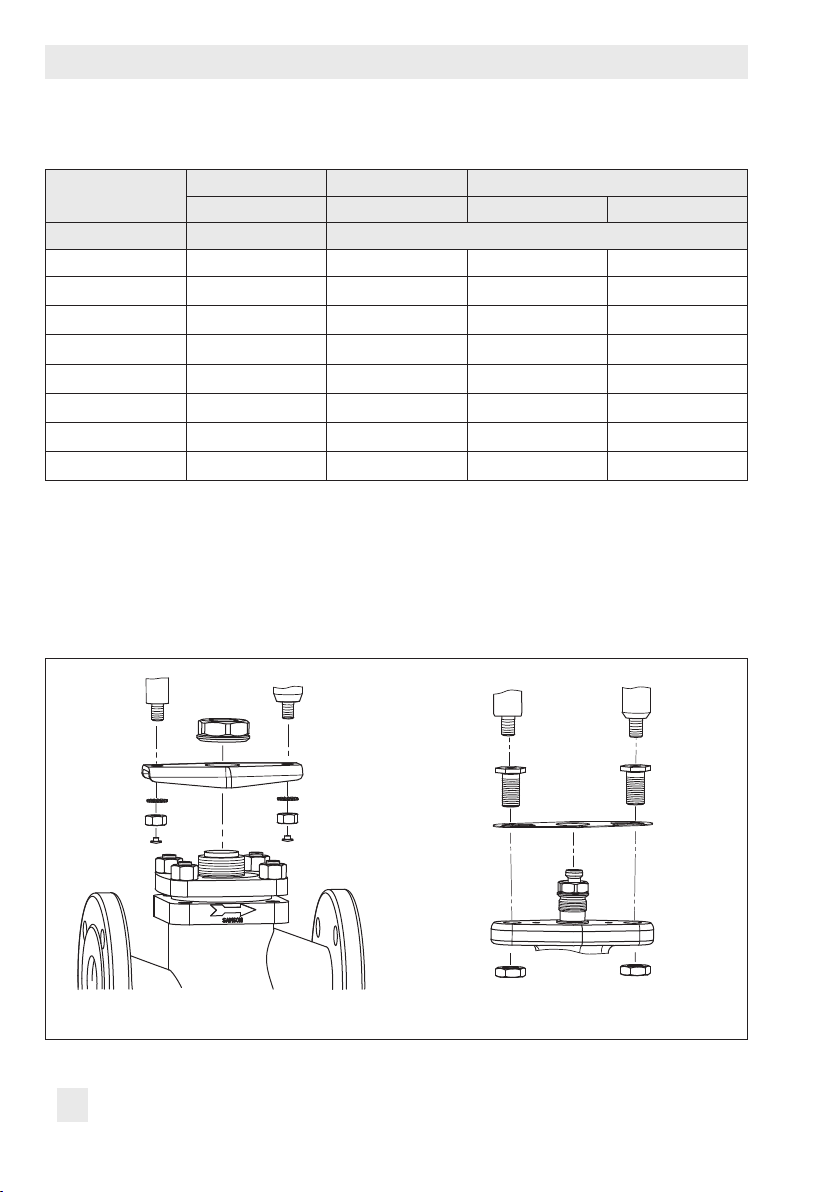
3.4 Mounting types
There are two types of mounting depending
on the valve/actuator combination: mounting using a crossbeam or rods (see Table1).
When the actuator is mounted to the valve
using a crossbeam (Form B, Fig.5), the actuator is fastened to the valve bonnet using a
central nut.
When the actuator is mounted using rods
(Form C, Fig.6), the actuator is connected to
the valve bonnet using rods. In this case, a
crossbeam is not required for mounting the
actuator. A plate keeps the correct distance
between rods.
Both mounting types are described in section5.1.
EB 8317 EN 15
Page 16
Design and principle of operation
Table1: Mounting types (see Fig.5 and Fig.6)
Actuator area 120cm² 350cm²
Travel 15mm 15mm 30mm
Type ... Valve Nominal size DN
3321 15 to 50 FormB –
3321 65 to 100 FormC FormC –
3321 100 – – FormC
3323 15 to 50 FormB – –
3323 65 to 80 – FormC –
3323 100 – – FormC
3531 15 to 80 FormB – –
3535 15 to 80 FormB – –
–
Fig.5: FormB: mounting using crossbeam Fig.6: FormC: mounting using rods
16 EB 8317 EN
Page 17
Design and principle of operation
Ø168
Ø280
3.5 Versions
− Standard version of Type3371
(120cm²)
The housings of Type 3371 Pneumatic
Actuators have an actuator area of
120cm² and are made of die-cast aluminum.
− Standard version of Type3371
(350cm²)
The housings of Type3371 Pneumatic
Actuators have an actuator area of
350cm² and are made of sheet steel.
− Version with travel stop
The Type3371 Actuators with 120cm²
actuator area can be tted with a mechanically adjustable travel stop. The
travel is reduced by up to 50% in both
directions of action (stem extends or retracts).
The travel stop is not available for
Type3371 (350cm²).
− Version with handwheel
The Type3371 Actuators (120cm²) can
be tted with an additional handwheel.
The handwheel is mounted on the top diaphragm case (A1) and is used to adjust
the travel manually.
The handwheel is not available for
Type3371 (350cm²).
3.6 Technical data
The nameplate provides information on the
actuator version (see section2.1).
Note
More information is available in Data Sheet
uT8317.
182
Fig.7: Dimensional drawing of 120cm² version Fig.8: Dimensional drawing of 350cm² version
EB 8317 EN 17
231
Page 18

Design and principle of operation
Table2: Technical data for Type3371 Pneumatic Actuator
Actuator area 120cm² 350cm²
Rated travel 15mm 30mm
Stem
Fail-safe action
Bench range in
bar
Supply pressure See section6.1 for restrictions
Ambient
temperature range
Dimensions Refer to Fig.7 Refer to Fig.8
Approx. weight 3.3kg 15kg
Compliance
Materials
Actuator housing GD-AlSi10Mg 1.0332
Diaphragm NBR NBR
Actuator stem 1.4305 1.4401/1.4404
retracts
(FE)
0.4 to
1.4
Stem
retracts
(FE)
–35 to +90°C –35 to +90°C
extends
1.4 to 2.3
Stem
(FA)
Stem
extends
(FA)
2.1 to
3.3
Stem
retracts
(FE)
1.5 to
2.1
Stem
extends
(FA)
2.1 to
2.7
retracts
Stem
(FE)
1.5 to
2.7
Stem
extends
(FA)
2.2 to
3.8
18 EB 8317 EN
Page 19

Measures for preparation
4 Measures for preparation
After receiving the shipment, proceed as follows:
1. Check the scope of delivery. Compare
the shipment received against the delivery note.
2. Check the shipment for transportation
damage. Report any damage to
SAMSON and the forwarding agent
(refer to delivery note).
4.1 Unpacking
Note
Do not remove the packaging until immediately before mounting.
Proceed as follows to lift and mount the actuator:
1. Remove the packaging from the actuator.
2. Dispose of the packaging in accordance
with the valid regulations.
4.2.1 Transporting
The actuator can be transported using lifting
equipment (e.g. crane or forklift).
Î Leave the actuator in its transport con-
tainer or on the pallet to transport it.
Î Observe the transport instructions.
Transport instructions
− Protect the actuator against external in-
uences (e.g. impact).
− Do not damage the corrosion protection
(paint, surface coatings). Repair any
damage immediately.
− Protect the actuator against moisture and
dirt.
− The permissible transportation tempera-
ture is between –20 and +65°C.
4.2.2 Lifting
Due to the low service weight, lifting equipment is not required to lift the actuator (e.g.
to mount it onto a valve).
4.2 Transporting and lifting
Tip
SAMSON's After-sales Service department
can provide more detailed transport and lifting instructions on request.
EB 8317 EN 19
Note
See valve documentation for more information on lifting the entire control valve assembly.
Page 20

Measures for preparation
4.3 Storage
!
NOTICE
Risk of actuator damage due to improper
storage.
− Observe storage instructions.
− Avoid long storage times.
− Contact SAMSON in case of different stor-
age conditions or long storage periods.
Note
We recommend regularly checking the actuator and the prevailing storage conditions
during long storage times.
Storage instructions
− When the valve and actuator are al-
ready assembled, observe the storage
conditions for control valves. See associated valve documentation.
− Protect the actuator against external in-
uences (e.g. impact).
− Do not damage the corrosion protection
(paint, surface coatings). Repair any
damage immediately.
− Protect the actuator against moisture and
dirt. Store it at a relative humidity of less
than 75%. In damp spaces, prevent condensation. If necessary, use a drying
agent or heating.
− Make sure that the ambient air is free of
acids or other corrosive media.
− The permissible storage temperature is
between –20 and +65°C.
− Do not place any objects on the actuator.
Special storage instructions for elastomers
Elastomer, e.g. actuator diaphragm
− To keep elastomers in shape and to pre-
vent cracking, do not bend them or hang
them up.
− We recommend a storage temperature of
15°C for elastomers.
− Store elastomers away from lubricants,
chemicals, solutions, and fuels.
Tip
SAMSON's After-sales Service department
can provide more detailed storage instructions on request.
20 EB 8317 EN
Page 21

4.4 Preparation for installation
Proceed as follows:
Î Check the actuator for damage.
Î Check to make sure that the type desig-
nation, material, and temperature range
of the actuator match the plant conditions.
Î Check the pressure gauge installed on
valve accessories to make sure it functions.
Î When the valve and actuator are al-
ready assembled, check the tightening
torques of the bolted joints (uAB0100).
Components may loosen during transport.
Measures for preparation
EB 8317 EN 21
Page 22

Mounting and start-up
5 Mounting and start-up
SAMSON control valves are delivered ready
for use. In special cases, the valve and actuator are delivered separately and must be
assembled on site. The procedure to mount
and start up the actuator are described in
following.
!
NOTICE
Risk of actuator damage due to excessively
high or low tightening torques.
Observe the specied torques on tightening
actuator components. Excessively tightened
torques lead to parts wearing out quicker.
Parts that are not tightened far enough may
loosen.
Observe the specied tightening torques
(uAB0100).
!
NOTICE
Risk of actuator damage due to the use of
unsuitable tools.
Only use tools approved by SAMSON
(uAB0100).
5.1 Mounting the actuator onto the valve
Note
− Table1 provides an overview of the possi-
ble combinations (FormB and FormC).
− Remove the mounted actuator before
mounting another actuator (see section9.2).
− Preloading the actuator springs increases
the thrust and reduces the travel range of
the actuator (see section5.3).
Tip
The valve and actuator are assembled with
special attention paid to the actuator's bench
range and direction of action. These details
are specied on the actuator nameplate (see
section2.1).
Note
See associated valve documentation for additional mounting instructions.
22 EB 8317 EN
Page 23

Mounting and start-up
A26
A10
A18
A13
A14
A11
A35
A31
•
Mounting with crossbeam Mounting without crossbeam
A16
A2
•
•
•
•
A1
•
•
A3
•
A1 Vent plug
A2 Bottom diaphragm case
A3 Actuator stem
A10 Spring
A11 Rod
A12 Bushing
A13 Diaphragm plate
A14 Diaphragm plate
Fig.9: Version with 120cm² actuator area
•
A30
•
•
A17
A16 Top diaphragm case
A17 Crossbeam
A18 Diaphragm
A26 Collar nut
A30/
Stem connector clamps
A31
A35 Pneumatic connection
A72 Rod nut
•
A12
•
A72
EB 8317 EN 23
Page 24

Mounting and start-up
A11
5.1.1 120cm² version
Mounting using crossbeam (FormB, see
Fig.10)
!
NOTICE
The actuator can be damaged.
Do not loosen the rod nuts (A72) that hold
the crossbeam (A17) on the rods (A11).
1. Remove the clamps of the stem connector
(A30) from the actuator.
2. Unscrew the central nut (98) from the
valve bonnet (2).
3. Press the plug together with the plug stem
rmly into the seat ring.
4. Place the actuator with the crossbeam
(A17) onto the thread of the valve bonnet (2), guiding the central nut (98) over
the plug stem and fasten it to the valve
bonnet. Observe tightening torques.
5. "Stem extends" direction of action: Position clamps of the stem connector (A30)
and screw them tight. Observe tightening
torques.
"Stem retracts" direction of action: apply enough pressure to the top diaphragm chamber to make the actuator
stem touch the plug stem. Position clamps
of the stem connector (A30) and screw
them tight. Observe tightening torques.
!
WARNING
Crush hazard arising from moving parts.
The actuator contains moving parts (actuator
stem), which can injure hands or ngers if
inserted into the actuator. Do not insert
hands or ngers into the yoke.
98
A17
2 Valve bonnet
98 Central nut
A11 Rod
A17 Crossbeam
A72 Rod nut
Fig.10: Mounting using crossbeam (FormB)
A72
2
24 EB 8317 EN
Page 25

Mounting and start-up
A11
A60
A72
A12
Mounting using rods (FormC, see Fig.11)
1. Remove the stem connector clamps (A31)
from the actuator.
2. Insert the rods (A11) into the bushings
(A12) and place them in the corresponding holes on the valve bonnet (2).
3. Tighten the rod nuts (A72) in alternating
sequence. Observe tightening torques.
4. "Stem extends" direction of action: position clamps of the stem connector (A31)
and screw them tight. Observe tightening
torques.
"Stem retracts" direction of action: apply enough pressure to the top diaphragm chamber to make the actuator
stem touch the plug stem. Position clamps
of the stem connector (A31) and screw
them tight. Observe tightening torques.
!
WARNING
Crush hazard arising from moving parts.
The actuator contains moving parts (actuator
stem), which can injure hands or ngers if
inserted into the actuator. Do not insert
hands or ngers into the yoke.
2 Valve bonnet
A11 Rod
A12 Bushing
A60 Plate
Fig.11: Mounting using rods (FormC), 120cm²
2
A72 Rod nut
EB 8317 EN 25
Page 26

Mounting and start-up
A33/A51
5.1.2 350cm² version
Mounting using rods (FormC, see Fig.12)
1. Remove the clamps of the stem connector
from the actuator.
2. Unscrew the rod nuts (A54) from the rods
(A33, A51). Leave the plate (A60) attached to the rods.
3. Place the actuator with the rod ends on
the valve bonnet (2).
4. Tighten the rod nuts (A54) in alternating
sequence. Make sure that the rods on the
bottom case do not turn. Observe tightening torques.
5. "Stem extends" direction of action: position clamps of the stem connector and
screw them tight. Observe tightening
torques.
"Stem retracts" direction of action: apply enough pressure to the top diaphragm chamber to make the actuator
stem touch the plug stem. Position the
clamps of the stem connector and screw
them tight. Observe tightening torques.
!
WARNING
Crush hazard arising from moving parts.
The actuator contains moving parts (actuator
stem), which can injure hands or ngers if
inserted into the actuator. Do not insert
hands or ngers into the yoke.
A60
2
Fig.12: Mounting using rods (FormC), 350cm²
2 Valve bonnet
A33/A51 Rod
A54 Rod nut
A60 Plate
A54
26 EB 8317 EN
Page 27

Mounting and start-up
A11
A11
A60
A72
A12
5.2 Changing the mounting type
The mounting type of actuators with 120cm²
actuator area can be changed subsequently.
Note
Table1 provides an overview of the possible
combinations (FormB and FormC).
98
A17
A72
5.2.1 Changing the mounting
type to mounting using
rods (FormB to FormC)
Note
For mounting the rods, a plate (A60) and
two bushings (A12) are required to adapt it
to the rod diameter.
1. Remove the clamps of the stem connec-
tor.
2. Unscrew the central nut (98).
3. Lift the actuator off the valve bonnet (2).
4. Undo the rod nuts (A72).
2
right)
A12 Bushing
A17 Crossbeam
A60 Plate
A72 Rod nut
2 Valve bonnet
98 Central nut
A11 Rod
Fig.13: Mounting types: mounting using crossbeam (FormB, left) and mounting using rods (FormC,
2
EB 8317 EN 27
Page 28

Mounting and start-up
5. Remove the crossbeam (A17).
6. Place the plate (A60) over the rods
(A11).
7. Screw bushings (A12) onto the thread of
the rods.
8. Place the rods (A11) on the valve bonnet
(2). Place the rod nuts (A72) on the
bushings (A12) and tighten in alternating
sequence. Observe tightening torques.
9. "Stem extends" direction of action: position clamps of the stem connector and
screw them tight. Observe tightening
torques.
"Stem retracts" direction of action: apply enough pressure to the top diaphragm chamber to make the actuator
stem touch the plug stem. Position the
clamps of the stem connector and screw
them tight. Observe tightening torques.
5.2.2 Changing the mounting
type to mounting using
a crossbeam (FormC to
FormB)
4. Undo the bushings (A12) from the rod
nuts.
5. Remove the plate (A60).
6. Place the crossbeam (A17) on the rods
(A11) in such a way that the bent side
faces away from the actuator housing.
Fasten the crossbeam using the rod nuts
(A72). Observe tightening torques.
7. Unscrew the central nut (98) from the
valve bonnet (2).
8. Place the actuator on the valve bonnet
(2). Tighten the central nut (98). Observe
tightening torques.
9. "Stem extends" direction of action: position clamps of the stem connector and
screw them tight. Observe tightening
torques.
"Stem retracts" direction of action: apply enough pressure to the top diaphragm chamber to make the actuator
stem touch the plug stem. Position the
clamps of the stem connector and screw
them tight. Observe tightening torques.
5.3 Preloading the springs
Note
To mount the crossbeam, a crossbeam
(A17), two serrated lock washers (A28), and
two caps (A70) are required.
1. Remove the clamps of the stem connector.
2. Undo the rod nuts (A72) from the bushings (A12).
3. Lift the actuator off the valve bonnet (2).
28 EB 8317 EN
By preloading the springs in the actuator, the
following can be achieved:
− The thrust is increased (only actuators
with "stem extends")
− In combination with a SAMSON valve:
the actuator travel range can be adapted
to a smaller valve travel range
Page 29

Mounting and start-up
Note
Actuators that have already been preloaded
by SAMSON without mounting the valve are
labeled correspondingly.
Additionally, these actuators can be identied by long bolts with nuts protruding from
the bottom diaphragm case. They allow the
spring compression to be relieved evenly
when disassembling the actuator (see section9.3).
5.3.1 Increasing the actuator thrust
The thrust can only be increased in actuators
with "stem extends" direction of action. To
achieve this, the springs of the actuators can
be preloaded by up to 25% of their travel or
bench range.
Example: Preloading is required for a signal
pressure range of1.4 to 2.3bar. 25% of
this span corresponds to 0.2bar. Therefore,
the signal pressure range is shifted by
0.2bar to 1.6 to 2.5bar. The new lower
signal pressure range value is 1.6bar and
the new upper signal pressure range value
2.5bar.
Î Write the new signal pressure range of
1.6 to 2.5bar on the actuator nameplate
as the operating range with preloaded
springs.
5.3.2 Adapting the travel range
In some cases, the valve and actuator have
different rated travels. Depending on the direction of action, proceed as follows:
Direction of action: actuator stem extends
Always use actuators with preloaded springs
when the valve's rated travel is smaller than
the rated travel of the actuator.
Example: DN15 valve with 7.5mm rated
travel and 120cm² actuator with 15mm rated travel; 1.4 to 2.3bar bench range.
The signal pressure for half of the actuator
travel (7.5mm) is 1.85bar. Adding it to the
lower signal pressure range value of 1.4bar
results in a signal pressure of 3.25bar required for preloading the springs. The new
lower signal range value is 3.25bar and the
new upper signal range value 4.15bar.
Î Write the new signal pressure range of
3.25 to 4.15bar on the actuator nameplate as the operating range with preloaded springs.
Direction of action: actuator stem retracts
The springs of actuators with "stem retracts"
action cannot be preloaded. When a
SAMSON valve is combined with an oversized actuator (e.g. the rated travel of the
actuator is larger than the rated travel of the
valve), only the rst half of the actuator's
bench range can be used.
Example: DN15 valve with 7.5mm rated
travel and 120cm² actuator with 15mm rated travel; 1.4 to 2.3bar bench range.
EB 8317 EN 29
Page 30

Mounting and start-up
At half the valve travel, the operating range
is between1.4 and 1.85bar.
5.4 Additional ttings
Vent plugs
Vent plugs are screwed into the exhaust air
ports of pneumatic and electropneumatic devices. They ensure that any exhaust air that
forms can be vented to the atmosphere (to
avoid excess pressure in the device). Furthermore, the vent plugs allow air intake to prevent a vacuum from forming in the device.
Î Locate the vent plug on the opposite side
to the workplace of operating personnel.
Î On mounting valve accessories, make
sure that they can be operated from the
workplace of the operating personnel.
Note
The workplace of operating personnel is the
location from which the valve, actuator, and
any mounted valve accessories can be accessed to operate them.
30 EB 8317 EN
Page 31

Operation
6 Operation
!
WARNING
Crush hazard arising from moving parts
(actuator stem).
Do not insert hands or ngers into the yoke
while the valve is in operation.
!
WARNING
Risk of personal injury when the actuator
vents.
Wear eye protection when working in close
proximity to the control valve.
!
NOTICE
Operating disturbed by a blocked actuator
stem.
Do not impede the movement of the actuator
stem by inserting objects into its path.
6.1 On/off service
In on/off service, the supply pressure must
be limited depending on the bench range or
signal pressure range of the actuator. The
applicable bench range or signal pressure
range which the actuator can move through
is written on the nameplate (see section2.1).
Bench range
0.4 to 1.4bar
1.4 to 2.3bar 5.3bar
1.5 to 2.1bar 5.1bar
Fail-safe
action
Actuator stem
retracts
Max.
supply
pressure
4.4bar
Actuator stem extends (FA)
With “stem extends” direction of action, the
supply pressure can be 6bar above the upper spring range value at the maximum.
With "stem extends" direction of action and
travel stop, the supply pressure must not exceed the upper spring range value by more
than 1.5bar.
Additional points that apply concerning op-
eration:
Î Label actuators with reduced supply
pressure with a sticker ("Max. supply
pressure limited to ... bar").
Î Only apply the signal pressure to the sig-
nal pressure connection (S) on the diaphragm chamber of the actuator which
does not contain any springs (see Fig.7).
Î Only use vent plugs that let air through
them (A1 in Fig.3).
Actuator stem retracts (FE)
For the direction of action "actuator stem retracts (FE)", the permissible supply pressure
must not exceed the upper bench range value by more than 3bar:
EB 8317 EN 31
Page 32

Operation
6.2 Reversal of the direction of
action
The direction of action (and fail-safe action)
of pneumatic actuators can be changed. The
fail-safe action is indicated on the nameplate
by a symbol (see section2.1).
Actuator stem extends (FA)
Actuator stem retracts (FE)
!
DANGER
Risk of bursting in the actuator.
Actuators are pressurized. Improper opening
can lead to actuator components bursting.
Before starting any work on the actuator, depressurize all plant sections concerned and
the actuator.
!
WARNING
Risk of personal injury due to preloaded
springs.
Actuators with preloaded springs are under
tension. They can be identied by the long
bolts protruding from the bottom of the actuator. Before starting any work on the actuator, relieve the compression from the preloaded springs (see section9.3).
!
NOTICE
Risk of malfunction due to incorrect details
on the nameplate after the reversal of the direction of action.
After reversal, the symbol and conguration
ID on the nameplate are no longer valid.
Contact SAMSON to request a new nameplate.
6.2.1 120cm² version
Reversal of the direction of action from
“stem extends” to “stem retracts”
1. Lift the actuator off the valve. See section9.2.
2. Without spring compression: unthread
the short nuts (A24) and bolts (A22) on
the diaphragm cases.
With spring compression: unthread the
short nuts (A24) and bolts (A22) on the
diaphragm cases. Unthread the long nuts
(A24) and bolts (A23) on the diaphragm
cases evenly in a crisscross pattern.
3. Lift off the top diaphragm case (A16)
and remove springs (A10).
4. Pull the actuator stem (A3) together with
the diaphragm plate (A14), diaphragm
(A18), and diaphragm plate (A13) out
of the bottom diaphragm case (A2).
5. Unscrew the collar nut (A26).
6. Remove the diaphragm plate (A14), diaphragm (A18), and diaphragm plate
(A13) from the actuator stem (A3) and
place them back on again in the reverse
order.
7. Tighten the collar nut (A26). Observe
tightening torques.
8. Apply a suitable lubricant to the actuator
stem (A3).
32 EB 8317 EN
Page 33

Operation
9. Place the springs (A10) in the bottom diaphragm case (A2), centering them in
the intended recesses.
10. Place the actuator stem (A3) together
with the diaphragm plate (A14), diaphragm (A18), and diaphragm plate
(A13) in the bottom diaphragm case
(A2). Make sure that the radial shaft seal
(A40) is not damaged.
11. Place on the top diaphragm case (A16).
12. Fasten the top and bottom diaphragm
cases (A16, A2) together using the nuts
(A24) and bolts (A22). Observe tightening torques.
13. Mount the actuator on the valve (see section5.1).
The actuator springs, which now push
against the diaphragm plate from below,
cause the actuator stem to retract. The
signal pressure is connected to the top
connection (S) on the top diaphragm
case. As a result, the actuator stem extends opposing the spring force as the
signal pressure increases.
14. Afx a new nameplate with changed
symbol and new conguration ID to the
actuator.
Reversal of the direction of action from
“stem retracts” to “stem extends”
1. Lift the actuator off the valve. See section9.2.
2. Unscrew the nuts (A24) and bolts (A22)
on the diaphragm case.
3. Lift off the top diaphragm case (A16).
4. Pull the actuator stem (A3) together with
the diaphragm plate (A14), diaphragm
(A18), and diaphragm plate (A13) out
of the bottom diaphragm case (A2).
5. Remove the springs (A10).
6. Unscrew the collar nut (A26).
7. Remove the diaphragm plate (A14), diaphragm (A18), and diaphragm plate
(A13) from the actuator stem (A3) and
place them back on again in the reverse
order.
8. Tighten the collar nut (A26). Observe
tightening torques.
9. Apply a suitable lubricant to the actuator
stem (A3).
10. Place the actuator stem (A3) together
with the diaphragm plate (A14), diaphragm (A18), and diaphragm plate
(A13) in the bottom diaphragm case
(A2). Make sure that the radial shaft seal
(A40) is not damaged.
11. Place the springs (A10) in the bottom diaphragm case (A2), centering them in
the intended recesses.
12. Place on the top diaphragm case (A16).
13. Without spring compression: fasten the
top and bottom diaphragm cases (A16,
A2) together with the nuts (A24) and
bolts (A22). Observe tightening torques.
With spring compression: fasten the top
and bottom diaphragm cases (A16, A2)
together with the nuts (A24) and long
bolts (A23). Fasten the nuts (A24) and
short bolts (A22). Observe tightening
torques.
EB 8317 EN 33
Page 34

Operation
14. Mount the actuator on the valve (see section5.1).
The actuator springs, which now push
against the diaphragm plate from above,
cause the actuator stem to extend. The
signal pressure is connected to the bottom connection (S) on the bottom diaphragm case. As a result, the actuator
stem retracts opposing the spring force
as the signal pressure increases.
15. Afx a new nameplate with changed
symbol and new conguration ID to the
actuator.
6.2.2 350cm² version
Reversal of the direction of action from
“stem extends” to “stem retracts”
1. Lift the actuator off the valve. See section9.2.
2. Without spring compression: unthread
the short nuts (A21) and bolts (A20) on
the diaphragm cases.
With spring compression: unthread the
short nuts (A21) and bolts (A20) on the
diaphragm cases. Unthread the long nuts
(A21) and bolts (A22) on the diaphragm
cases evenly in a crisscross pattern.
3. Lift off the top diaphragm case (A1) and
remove springs (A10).
4. Pull the actuator stem (A7) together with
the diaphragm plate (A5) and diaphragm (A4) out of the bottom diaphragm case (A2).
5. Unscrew the collar nut (A15).
6. Take the compressor (A27), diaphragm
plate (A5), and diaphragm (A4) off the
actuator stem (A7) and place them back
on again in the reverse order.
7. Tighten the collar nut (A15). Observe
tightening torques.
8. Apply a suitable lubricant to the actuator
stem (A7).
9. Place the springs (A10) in the bottom diaphragm case (A2), centering them in
the intended recesses.
10. Insert the actuator stem (A7) together
with the diaphragm plate (A5) and diaphragm (A4) into the bottom diaphragm
case (A2). Make sure that the radial
shaft seal (A40) is not damaged.
11. Place on the top diaphragm case (A1).
12. Fasten the top and bottom diaphragm
cases (A1, A2) together using the nuts
(A21) and bolts (A20).
The actuator springs, which now push
against the diaphragm plate from below,
cause the actuator stem to retract. The
signal pressure is connected to the top
connection (S) on the top diaphragm
case. As a result, the actuator stem extends opposing the spring force as the
signal pressure increases.
13. Afx a new nameplate with changed
symbol and new conguration ID to the
actuator.
Reversal of the direction of action from
“stem retracts” to “stem extends”
1. Lift the actuator off the valve. See section9.2.
34 EB 8317 EN
Page 35

Operation
A75
2. Unscrew the nuts (A21) and bolts (A20)
on the diaphragm case.
3. Lift off the top diaphragm case (A1).
4. Pull the actuator stem (A7) together with
the diaphragm plate (A5) and diaphragm (A4) out of the bottom diaphragm case (A2).
5. Remove the springs (A10).
6. Unscrew the collar nut (A15).
7. Take the compressor (A27), diaphragm
plate (A5), and diaphragm (A4) off the
actuator stem (A7) and place them back
on again in the reverse order.
8. Tighten the collar nut (A15).
9. Apply a suitable lubricant to the actuator
stem (A7).
10. Insert the actuator stem (A7) together
with the diaphragm plate (A5) and diaphragm (A4) into the bottom diaphragm
case (A2). Make sure that the radial
shaft seal (A40) is not damaged.
11. Place the springs (A10) in the bottom diaphragm case (A2), centering them in
the intended recesses.
12. Place on the top diaphragm case (A1).
13. Without spring compression: fasten the
top and bottom diaphragm cases (A1,
A2) together with the nuts (A21) and
bolts (A20). Observe tightening torques.
With spring compression: fasten the top
and bottom diaphragm cases (A1, A2)
together with the nuts (A21) and long
bolts (A22). Fasten the nuts (A21) and
short bolts (A20). Observe tightening
torques.
The actuator springs, which now push
against the diaphragm plate from above,
cause the actuator stem to extend. The
signal pressure is connected to the bottom connection (S) on the bottom diaphragm case. As a result, the actuator
stem retracts opposing the spring force
as the signal pressure increases.
A79
A73 Spindle
A75 Cover
A76 Lock nut
A77 Top diaphragm case
A79 Lock nuts
Fig.14: Travel stop for 120cm² version
A73
A76
A77
EB 8317 EN 35
Page 36

Operation
A63/64
A62
14. Afx a new nameplate with changed
symbol and new conguration ID to the
actuator.
6.3 Version with travel stop
The Type3371 Pneumatic Actuator
(120cm²) can optionally be tted with a
travel stop to limit the minimum and maximum travel. These stops can be combined.
A65
6.3.1 Bottom travel stop (minimum travel)
1. Loosen lock nut (A76) and remove cover
(A75).
2. Loosen the lock nuts (A79).
3. Move actuator to the position of mini-
mum travel.
4. Screw the bottom nut (A79) on as far as
it will go and lock this position with the
top nut (A79).
A60 Upper actuator section
A68
A66
A62 Spindle
A63/64 Cover
A65 Pin
A66 Sleeve
A68 Retaining washer
A60
Fig.15: Handwheel with 120cm² version
36 EB 8317 EN
Page 37

Operation
Note
If the minimum travel is not to be limited,
thread the nuts (A79) until they reach the
end of the spindle (A73) and lock them in
position.
5. Attach the cover (A75) and retighten the
lock nut (A76).
6.3.2 Top travel stop (maximum
travel)
1. Loosen the lock nut (A76).
2. Unscrew the cover (A75).
3. Move actuator to the position of maximum travel.
4. Screw back on the cover (A75) as far it
will go and retighten the lock nut (A76).
6.4 Version with handwheel
The Type3371 Pneumatic Actuator
(120cm²) can optionally tted with a handwheel. The actuator stem can be moved over
a spindle. The actuator travel is adjusted
against the spring force (see Fig.15).
The pin (A65) moves up or down in the oblong hole of the sleeve (A66) depending on
which way the handwheel is turned. This
causes the spindle (A62) to either extend or
retract.
6.4.1 Operating the handwheel of version with
"stem extends" direction
of action
1. Turn the handwheel counterclockwise.
The actuator stem retracts causing a
globe valve to open.
2. Retract the actuator stem up to the re-
quired position.
6.4.2 Operating the handwheel of version with
"stem retracts" direction
of action
1. Turn the handwheel clockwise. The actu-
ator stem extends causing a globe valve
to close.
2. Extend the actuator stem up to the re-
quired position.
Note
If you want to t a handwheel to an actuator,
contact SAMSON's After-sales Service department.
EB 8317 EN 37
Page 38

Servicing
7 Servicing
Depending on the operating conditions,
check the actuator at regular intervals to prevent possible failure before it can occur.
Tip
SAMSON's After-sales Service department
can support you to draw up an inspection
plan for your plant.
!
DANGER
Risk of bursting in the actuator.
Actuators are pressurized. Improper opening
can lead to actuator components bursting.
Before starting any work on the actuator, depressurize all plant sections concerned and
the actuator.
!
WARNING
Risk of personal injury due to preloaded
springs.
Actuators with preloaded springs are under
tension. They can be identied by the long
bolts protruding from the bottom of the actuator.
Before starting any work on the actuator, relieve the compression from the preloaded
springs (see section9.3).
!
NOTICE
Risk of actuator damage due to incorrect
service or repair.
Service and repair work must only be performed by trained staff.
!
NOTICE
Risk of actuator damage due to excessively
high or low tightening torques.
Observe the specied torques on tightening
actuator components. Excessively tightened
torques lead to parts wearing out quicker.
Parts that are not tightened far enough may
impair the actuator functioning properly.
Observe the specied tightening torques
(uAB0100).
!
NOTICE
Risk of actuator damage due to the use of
unsuitable tools.
Only use tools approved by SAMSON
(uAB0100).
!
NOTICE
Risk of actuator damage due to the use of
unsuitable lubricants.
Only use lubricants approved by SAMSON
(uAB0100).
Note
− The product warranty becomes void if ser-
vice or repair work not described in these
instructions is performed without prior
agreement by SAMSON's After-sales Service department.
− Only use original spare parts by
SAMSON, which comply with the original
specications.
38 EB 8317 EN
Page 39

Servicing
7.1 Replacing the diaphragm
7.1.1 120cm² version
Tip
Before dismantling the actuator, mark both
diaphragm cases (A16, A2) to ensure that
the pneumatic connections are mounted correctly later on reassembling the actuator.
Version with direction of action "actuator
stem extends" (FA)
1. Lift the actuator off the valve. See section9.2.
2. Without spring compression: unthread
the short nuts (A24) and bolts (A22) on
the diaphragm cases.
With spring compression: unthread the
short nuts (A24) and bolts (A22) on the
diaphragm cases. Unthread the long nuts
(A24) and bolts (A23) on the diaphragm
cases evenly in a crisscross pattern.
3. Lift off the top diaphragm case (A16)
and remove springs (A10).
4. Pull the actuator stem (A3) together with
the diaphragm plate (A14), diaphragm
(A18), and diaphragm plate (A13) out
of the bottom diaphragm case (A2).
5. Unscrew the collar nut (A26).
6. Remove the diaphragm plate (A14), diaphragm (A18), and diaphragm plate
(A13) from the actuator stem (A3).
7. Place the new diaphragm on the diaphragm plate (A13). Place on the diaphragm plate (A14).
8. Check the sealing element on the collar
nut (A26). If necessary, renew it.
9. Tighten the collar nut (A26). Observe
tightening torques.
10. Apply a suitable lubricant to the actuator
stem (A3).
11. Place the actuator stem (A3) together
with the diaphragm plate (A14), diaphragm (A18), and diaphragm plate
(A13) in the bottom diaphragm case
(A2). Make sure that the radial shaft seal
(A40) is not damaged.
12. Place the springs (A10) into the bottom
diaphragm case, centering them in the
intended recesses.
13. Place on the top diaphragm case (A16).
14. Without spring compression: fasten the
top and bottom diaphragm cases (A16,
A2) together with the nuts (A24) and
bolts (A22). Observe tightening torques.
With spring compression: fasten the top
and bottom diaphragm cases (A16, A2)
together with the nuts (A24) and long
bolts (A23). Fasten the nuts (A24) and
short bolts (A22). Observe tightening
torques.
15. Mount the actuator on the valve (see section5.1).
Version with direction of action "actuator
stem retracts" (FE)
1. Lift the actuator off the valve. See section9.2.
EB 8317 EN 39
Page 40

Servicing
A3
A26
A10
A18
A13
A14
A11
A35
A31
A72
A12
•
Mounting with crossbeam Mounting without crossbeam
A16
A2
•
•
•
•
A1
•
•
•
A1 Vent plug
A2 Bottom diaphragm case
A3 Actuator stem
A10 Spring
A11 Rod
A12 Bushing
A13 Diaphragm plate
A14 Diaphragm plate
Fig.16: Version with 120cm² actuator area
•
A30
•
•
A17
A16 Top diaphragm case
A17 Crossbeam
A18 Diaphragm
A26 Collar nut
A30/
Stem connector clamps
A31
A35 Pneumatic connection
A72 Rod nut
•
•
40 EB 8317 EN
Page 41

Servicing
2. Unscrew the nuts (A24) and bolts (A22)
on the diaphragm case.
3. Lift off the top diaphragm case (A16).
4. Pull the actuator stem (A3) together with
the diaphragm plate (A14), diaphragm
(A18), and diaphragm plate (A13) out
of the bottom diaphragm case (A2).
5. Unscrew the collar nut (A26).
6. Remove the diaphragm plate (A14), diaphragm (A18), and diaphragm plate
(A13) from the actuator stem (A3).
7. Place the new diaphragm on the diaphragm plate (A13). Place on the diaphragm plate (A14).
8. Check the sealing element on the collar
nut (A26). If necessary, renew it.
9. Tighten the collar nut (A26). Observe
tightening torques.
10. Check whether the springs (A10) rest
correctly in the bottom diaphragm case
(A2).
11. Apply a suitable lubricant to the actuator
stem (A3).
12. Place the actuator stem (A3) together
with the diaphragm plate (A14), diaphragm (A18), and diaphragm plate
(A13) in the bottom diaphragm case
(A2). Make sure that the radial shaft seal
(A40) is not damaged.
13. Place on the top diaphragm case (A16).
14. Fasten the top and bottom diaphragm
cases (A16, A2) together using the nuts
(A24) and bolts (A22). Observe tightening torques.
15. Mount the actuator on the valve (see section5.1).
7.1.2 350cm² version
Tip
Before dismantling the actuator, mark both
diaphragm cases (A1, A2) to ensure that the
pneumatic connections are mounted correctly later on reassembling the actuator.
Version with direction of action "actuator
stem extends" (FA)
1. Lift the actuator off the valve. See section9.2.
2. Without spring compression: unthread
the short nuts (A21) and bolts (A20) on
the diaphragm cases.
With spring compression: unthread the
short nuts (A21) and bolts (A20) on the
diaphragm cases. Unthread the long nuts
(A21) and bolts (A22) on the diaphragm
cases evenly in a crisscross pattern.
3. Lift off the top diaphragm case (A1) and
remove springs (A10).
4. Pull the actuator stem (A7) together with
the diaphragm plate (A5) and diaphragm (A4) out of the bottom diaphragm case (A2).
5. Unscrew the collar nut (A15).
6. Take the compressor (A27), diaphragm
plate (A5), and diaphragm (A4) off the
actuator stem (A7).
7. Place the new diaphragm on the diaphragm plate (A5).
EB 8317 EN 41
Page 42

Servicing
A61
A10
A1
S
A15
A51
A50
A25
A20
A21
A27
A1
A5
A4
A2
A33
A1 Top diaphragm case
A2 Bottom diaphragm case
A4 Diaphragm
A5 Diaphragm plate
A7 Actuator stem
A10 Spring
A15 Collar nut
•
•
•
•
•
A40
A42
A41
•
A7
A20 Hexagon bolt
A21 Hexagon nut
A25 Washer
A27 Compressor
A33 Rod
A40 Radial shaft seal
A41 Wiper ring
•
•
A60
A54
•
•
•
•
•
•
•
•
•
•
A42 Dry bearing
A50 Screw for rod (A51)
A51 Rod
A54 Rod nut
A60 Plate
A61 Pneumatic connection
S Signal pressure
connection (stem retracts)
Fig.17: Type3371 with 350cm² actuator area
42 EB 8317 EN
Page 43

Servicing
8. Place the compressor (A27) onto the actuator stem (A7).
9. Check the sealing element on the collar
nut (A15). If necessary, renew it.
10. Tighten the collar nut (A15). Observe
tightening torques.
11. Apply a suitable lubricant to the actuator
stem (A7).
12. Insert the actuator stem (A7) together
with the diaphragm plate (A5) and diaphragm (A4) into the bottom diaphragm
case (A2). Make sure that the radial
shaft seal (A40) is not damaged.
13. Place the springs (A10) into the bottom
diaphragm case, centering them in the
intended recesses.
14. Place on the top diaphragm case (A1).
15. Without spring compression: fasten the
top and bottom diaphragm cases (A1,
A2) together with the nuts (A21) and
bolts (A20). Observe tightening torques.
With spring compression: fasten the top
and bottom diaphragm cases (A1, A2)
together with the nuts (A21) and long
bolts (A22). Fasten the nuts (A21) and
short bolts (A20). Observe tightening
torques.
16. Mount the actuator on the valve (see section5.1).
Version with direction of action "actuator
stem retracts" (FE)
1. Lift the actuator off the valve. See section9.2.
2. Unscrew the nuts (A21) and bolts (A20)
on the diaphragm case.
3. Lift off the top diaphragm case (A1).
4. Pull the actuator stem (A7) together with
the diaphragm plate (A5) and diaphragm (A4) out of the bottom diaphragm case (A2).
5. Unscrew the collar nut (A15).
6. Take the compressor (A27), diaphragm
plate (A5), and diaphragm (A4) off the
actuator stem (A7).
7. Place the new diaphragm on the diaphragm plate (A5).
8. Place the compressor (A27) onto the actuator stem (A7).
9. Check the sealing element on the collar
nut (A15). If necessary, renew it.
10. Tighten the collar nut (A15). Observe
tightening torques.
11. Check whether the springs (A10) rest
correctly in the bottom diaphragm case
(A2).
12. Apply a suitable lubricant to the actuator
stem (A7).
13. Insert the actuator stem (A7) together
with the diaphragm plate (A5) and diaphragm (A4) into the bottom diaphragm
case (A2). Make sure that the radial
shaft seal (A40) is not damaged.
14. Place on the top diaphragm case (A1).
15. Fasten the top and bottom diaphragm
cases (A1, A2) together using the nuts
(A21) and bolts (A20). Observe tightening torques.
16. Mount the actuator on the valve (see section5.1).
EB 8317 EN 43
Page 44

Servicing
7.2 Preparation for return shipment
Defective actuators can be returned to
SAMSON for repair.
Proceed as follows to return valves to
SAMSON:
1. Put the control valve out of operation.
See associated valve documentation.
2. Remove the actuator from the valve (see
section9.2).
3. Send the actuator to your nearest
SAMSON subsidiary. SAMSON
subsidiaries are listed on our website at
uwww.samson.de > Contact.
7.3 Ordering spare parts and operating supplies
Contact your nearest SAMSON subsidiary
or the SAMSON After-sales Service department for information on spare parts, lubricants, and tools.
Spare parts
See section10.2 for details on spare parts.
Lubricant
Details on suitable lubricants can be found in
the document uAB0100.
Tools
Details on suitable tools can be found in the
document uAB0100.
44 EB 8317 EN
Page 45

Malfunctions
8 Malfunctions
Depending on the operating conditions, check the actuator at certain intervals to prevent
possible failure before it can occur. Operators are responsible for drawing up an inspection
plan.
Tip
SAMSON's After-sales Service department can support you to draw up an inspection plan
for your plant.
Troubleshooting
Malfunction Possible reasons Recommended action
Actuator stem does not move on
demand.
Actuator stem does not stroke
through its complete travel
range.
Actuator is blocked. Check attachment.
Unblock the actuator.
Insufcient signal pressure Check the signal pressure.
Check the signal pressure line for
leakage.
Signal pressure not connected to
the correct diaphragm chamber.
Travel stop active See section6.3.
Insufcient signal pressure Check the signal pressure.
Valve accessories incorrectly set. Check the actuator without valve
See section3.2.
Check the signal pressure line for
leakage.
accessories.
Check the settings of the valve
accessories.
Note
Contact SAMSON's After-sales Service department for malfunctions not listed in the table.
EB 8317 EN 45
Page 46

Decommissioning and disassembly
9 Decommissioning and disas-
sembly
!
DANGER
Risk of bursting in the actuator.
Actuators are pressurized. Improper opening
can lead to actuator components bursting.
Before starting any work on the actuator, depressurize all plant sections concerned and
the actuator.
!
WARNING
Risk of personal injury due to preloaded
springs.
Actuators with preloaded springs are under
tension. They can be identied by the long
bolts protruding from the bottom of the actuator. Before starting any work on the actuator, relieve the compression from the preloaded springs (see section9.3).
9.1 Decommissioning
To decommission the actuator for service and
repair work or disassembly, proceed as follows:
1. Put the control valve out of operation.
See associated valve documentation.
2. Disconnect the pneumatic air supply to
depressurize the actuator.
9.2 Removing the actuator from the valve
9.2.1 120cm² version
For mounting using crossbeam (FormB)
1. Put the control valve out of operation.
See associated valve documentation.
2. Remove the clamps of the stem connector
(A30) from the actuator.
3. Removing actuators with "stem ex-
tends" action with/without preloaded
springs: to undo the central nut (98), apply approx. 50% signal pressure to open
the valve.
4. Unscrew the central nut (98) from the
plug stem.
5. Disconnect the signal pressure again.
6. In the "actuator stem retracts" version:
detach the external piping.
7. Lift the central nut (98) and actuator off
the valve.
8. Screw tight the central nut (98) on the
valve.
9. Screw tight the stem connector clamps
(A30) onto the actuator. Observe tightening torques.
!
NOTICE
The actuator can be damaged.
Do not loosen the rod nuts (A72) that hold
the crossbeam (A17) on the rods (A11).
46 EB 8317 EN
Page 47

Decommissioning and disassembly
For mounting using rods (FormC)
1. Put the control valve out of operation.
See associated valve documentation.
2. Remove the clamps of the stem connector
(A31) from the actuator.
3. Undo the rod nuts (A72) in alternating
sequence.
4. Pull the rods (A11) with bushings (A12)
out of the holes in the valve bonnet (2).
5. Remove the bushings (A12) from the actuator and thread the rod nuts (A72) onto the rods (A11).
6. Screw tight the stem connector clamps
(A31) onto the actuator. Observe tightening torques.
9.2.2 350cm² version
1. Put the control valve out of operation.
See associated valve documentation.
2. In the "actuator stem retracts" version:
detach the external piping.
3. Remove the clamps of the stem connector
(A12) from the actuator.
4. Undo the rod nuts (A54) in alternating
sequence.
5. Pull the rods (A33, A51) out of the holes
in the valve bonnet (2).
6. Thread the rod nuts (A54) onto the rods
(A33, A51) on the actuator.
7. Screw tight the stem connector clamps
(A12) onto the actuator. Observe tightening torques.
9.3 Relieving the spring compression in the actuator
1. Undo the short nuts and bolts on the dia-
phragm cases.
2. Undo the the long bolts on the dia-
phragm cases evenly in a crisscross pattern.
9.4 Disposal
Î Observe local, national, and internation-
al refuse regulations.
Î Do not dispose of components, lubri-
cants, and hazardous substances together with your other household waste.
EB 8317 EN 47
Page 48

Annex
10 Annex
10.1 After-sales service
Contact SAMSON's After-sales Service department for support concerning service or
repair work or when malfunctions or defects
arise.
E-mail
You can reach the After-sales Service Department at aftersalesservice@samson.de.
Addresses of SAMSONAG and its subsidiaries
The addresses of SAMSON AG, its subsidiaries, representatives, and service facilities
worldwide can be found on the SAMSON
website, in all SAMSON product catalogs or
on the back of these Mounting and Operating Instructions.
Required specications
Please submit the following details:
− Order number and position number in
the order
− Type, model number, actuator area, trav-
el and bench range (e.g. 0.2 to 1bar) or
the operating range of the actuator
− Type designation of mounted valve (if
applicable)
− Installation drawing
48 EB 8317 EN
Page 49

10.2 Spare parts
Annex
Type3371 Actuator with 120cm² actuator area
1 Vent plug
2 Bottom diaphragm case
2.2 Radial shaft seal
2.3 Wiper ring
2.4 Dry bearing
3 Actuator stem
4 Stopper
5 Label (preloading)
6 Nameplate
7/8/9/10 Spring
11 Rod
12 Bushing
13 Diaphragm plate
14 Diaphragm plate
16 Top diaphragm case
17 Crossbeam
18 Diaphragm
20 Screw plug
21 Screw-on cap
22 Hexagon bolt
23 Hexagon bolt
24 Hexagon nut
25 Hexagon nut
26 Collar nut
27 Washer
28 Serrated lock washer
30/31 Stem connector clamps
35 Pneumatic connection
37 Rod
60 Upper actuator section
62 Spindle
63 Device cover
64 Device cover
65 Pin
1)
1)
1)
1)
1)
66 Sleeve
1)
68 Retaining washer
70 Protective cap
72 Rod nut (hexagon nut)
73 Spindle
74 Sleeve
74.1 Dry bearing
2)
2)
2)
74.2 Radial shaft seal
75 Cover
76 Lock nut
2)
2)
77 Top diaphragm case
79 Lock nut
1)
Only for version with handwheel
2)
Only for version with travel stop
2)
1)
2)
2)
EB 8317 EN 49
Page 50

Version with hand-
wheel
Type3371 Actuator with
120cm² actuator area
60
63
66
60
21
24
40
60
62
7/8/9/10
26
14
18
13
27
5
68
65
2
6
64
22
23
50 EB 8317 EN
Page 51

Mounting
without cross-
beam
75
79
74
74.2
74.1
76
21
24
27
77
73
35
20/1
11
12
72
Version with travel
stop
Standard version
21
24
27
16
4
5
Mounting with
crossbeam
4
5
2.2
2.4
2.3
35
20/1
11
3
30
3
31
17
28
25
70
EB 8317 EN 51
Page 52

Annex
Type3371 Actuator with 350cm² actuator area
1 Top diaphragm case
2 Bottom diaphragm case
4 Diaphragm
5 Diaphragm plate
7 Actuator stem
10/11 Spring
12 Stem connector clamp
13 Stem connector clamp
14 Screw
15 Collar nut
16 Vent plug
20 Hexagon bolt
21 Hexagon nut
22 Hexagon bolt (preloading)
25 Washer
27 Compressor
33 Rod
37 Washer
40 Radial shaft seal
41 Wiper ring
42 Dry bearing
50 Screw for rod (51)
51 Rod
52 Washer (version with "actuator stem re-
tracts" only)
53 O-ring
54 Rod nut
55 Bushing
56 Snap ring
57 O-ring
60 Plate
61 Pneumatic connection
100 Nameplate
101 Label (preloading)
52 EB 8317 EN
Page 53

Type3371 Actuator with 350cm² actuator area
16
37
22
41
7
40
55
42
12
101100
20
25
1
11
10
15
50
52
2
25
21
53
56
61
13
14
51
33
60
54
EB 8317 EN 53
5
4
2
7
57
Page 54

54 EB 8317 EN
Page 55

EB 8317 EN 55
Page 56

SAMSON AG · MESS- UND REGELTECHNIK
Weismüllerstraße 3 · 60314 Frankfurt am Main, Germany
Phone: +49 69 4009-0 · Fax: +49 69 4009-1507
samson@samson.de · www.samson.de
EB 8317 EN
2017-05-04 · English
 Loading...