

Pneumatic Actuators up to 700 cm²
Type 3271 and
Type 3277 for integral positioner attachment
Application
Linear actuators in particular for attachment to Series 240, 250,
280 Control Valves and Type 3510 Micro-flow Valves
Diaphragm area 60 to 700 cm²
Rated travel 7.5 to 30 mm
The Types 3271 and 3277 Pneumatic Actuators contain a roll
ing diaphragm and internal springs.
Special features
Low overall height
•
Powerful thrust at high response speed
•
Low friction
•
Various bench ranges by varying the number of springs or
•
their compression
No special tools required to change the bench range and to
•
reverse the actuator action (also version with handwheel)
• Permissible operating temperatures from –50 to +120 °C
• Direct attachment of accessories on additional yoke for
Type 3277 with concealed travel pick-off (Figs. 2, 3 and 6)
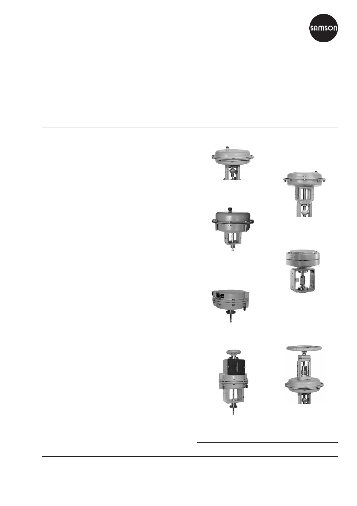
Pneumatic actuator versions
– Type 3271 · Diaphragm areas 80, 240, 350, 700 cm²
(Fig. 1), optional stainless steel version (made of 1.4301 for
240, 350 and 700 cm²)
– Type 3277 · Diaphragm areas 240, 350, 355, 700 cm² for
direct attachment of accessories (Figs. 2, 3), optional stainless steel version (made of 1.4301 for 240, 350, 700 cm²)
–
Type 3271-52 · Diaphragm area 60 cm², aluminum hous
ing, especially for Type 3510 Micro-flow Valve (Fig. 4 and
Data Sheet T 8091 EN)
–
Type 3271-5 · Diaphragm area 120 cm², die-cast alumi
num housing (Fig. 5), optionally with additional handwheel
(Fig. 13a)
–
Type 3277-5 · Diaphragm area 120 cm², die-cast alumi
num housing for direct attachment of accessories (Fig. 10),
optionally with additional handwheel (Figs. 6 and 13b)
–
Types 3271 or 3277 · Additional handwheel with dia
phragm areas of 240, 350 or 700 cm² (Fig. 7, 12 and Data
Sheet T 8312 EN)
–
Type 3271 · Mechanical travel stop(Fig. 14), min. or max.
travel mechanically adjustable in versions with 120, 240,
350 or 700 cm²
–
Type 3271/7 · Fire-Lock version (Fig. 15) fail-safe action
in case of fire, in versions with 240, 350, 700 cm²
Further versions
–
Versions for other control media(e.g. water) · Details avail
able on request
-
Fig. 1 · Type 3271
Fig. 2 · Type 3277
Fig. 3 · Type 3277, 355 cm²
-
Fig. 4 · Type 3271-52
-
Fig. 5 · Type 3271-5
-
-
Fig. 6 · Type 3277-5
-
with additional handwheel
Fig. 7 · Type 3271 with
additional handwheel
Associated Mounting and Operating Instructions
Type 3271 Pneumatic Actuator EB 8310 EN
Type 3277 Pneumatic Actuator EB 8311 EN
Edition March 2010
Data Sheet T 8310-1 EN
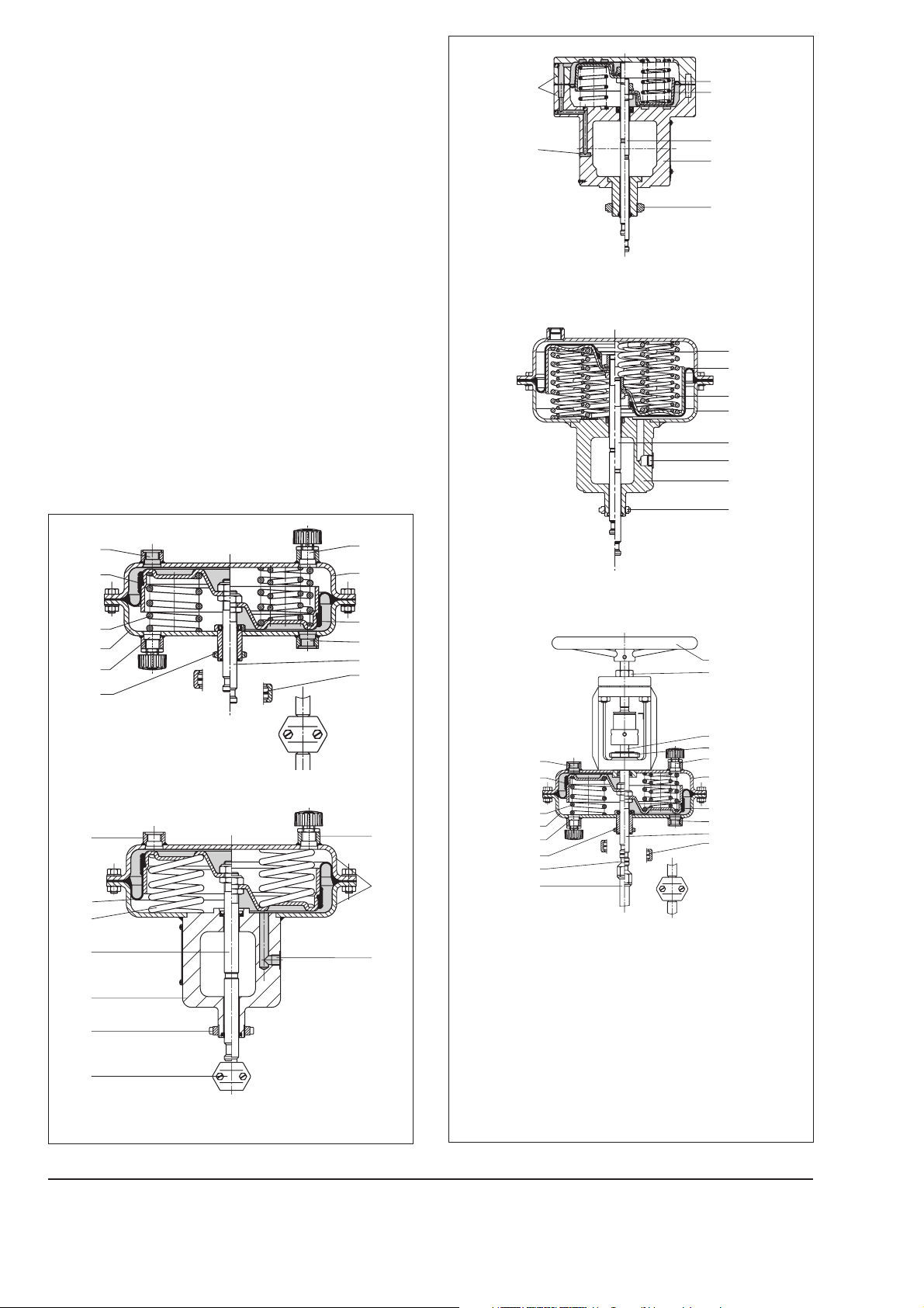
Principle of operation
The signal pressure p
generates a forceF=pstx A on the dia
st
phragm area A (2). This force is balanced by the actuator
springs (4). Taking into account the rated travel, the number of
springs and their compression determine the bench range. The
travel H is proportional to the signal pressure p
. The operating
st
direction of the actuator stem (7) depends on the arrangement
of the springs and the signal pressure connection (1).
The stem connector (8) connects the actuator stem (7) with the
plug stem of the valve.
The adjustable mechanical travel stop (Fig. 14) is suitable for
actuators made of sheet steel with effective diaphragm areas of
120, 240, 350 or 700 cm². Using the travel stop, the actuator
travel can be limited by up to 50 % in both directions (actuator
stem extends or retracts) and permanently adjusted.
Actuators are available with the following fail-safe actions:
“Actuator stem extends (FA)“
The springs cause the actuator stem to move to the lower end
position (sectional drawings, right) when the diaphragm is re
lieved of pressure or when the supply air fails.
“Actuator stem retracts (FE)“
The springs cause the actuator stem to retract (sectional draw
ings, left) when the diaphragm is relieved of pressure or when
the supply air fails.
-
5
1
Fig. 10 · Type 3277-5 for direct attachment of accessories
-
-
2
4
7
11
6
5
2
4
5
7
1
11
1
2
4
5
3
6
Fig. 8 · Type 3271 (right: with additional springs)
1
2
4
7
11
6
8
Fig. 9 · Type 3277 for direct attachment of accessories
6
3
5
Fig. 11 · Type 3277, version with 355 cm² actuator area
2
1
7
8
1
2
4
3
5
5
3
6
9
10
23
18
12
6
3
5
2
1
7
8
Fig. 12 · Type 3271 with additional handwheel
1
Legend (Figs. 8 to 15)
1 Signal pressureconnection
2 Diaphragm
3 Vent
4 Springs
5 Diaphragm cases
6 Annular nut
7 Actuator stem
8 Stem connector
11 Yoke
12 Actuator stem to
handwheel
14 Cap
15 Nut
16 Spindle
17 Plain bearing
18 Lock nut
23 Handwheel
2
T 8310-1 EN

17
16
14
18
15
1
2
3
5
4
5
3
6
2
1
7
8
Fig. 14 · Type 3271 with adjustable travel stop
Figs. 13a, 13b · Type 3271-5 and Type 3277-5,
fail-safe action “stem extends”,
both with additional handwheel
Fig. 15 · Fire-Lock version, in fail-safe position (right)
Table 1a · Technical data for Type 3271 Pneumatic Actuator
1)
Type 3271-5
Type 3277-5
–35 to 90 °C
Version Type 3271
Type 3271
Stainless steel
Type 3277
Type 3277
Stainless steel
Type 3271-52
f. micro-flow valve
Diaphragm area cm² 80* · 240 · 350 · 700 240 · 350 · 355* · 700 60 120
Max. supply pressure 6 bar · See restrictions in on/off service on page 6
1)
Permissible operating
temperatures
–35 to 90 °C
–50 to 120 °C2)made of special material EPDM, for air free of oil and
grease and actuator versions with 240, 350 and 700 cm²
made of standard material NBR
–35 to 80 °C
Up to 80 °C in Fire-Lock version (for 240, 350 and 700 cm²)
1)
Materials
Rolling diaphragm NBR (nitrile rubber) with fabric reinforcement
EPDM with fabric reinforcement (not for 355 cm²)
NBR with fabric reinforcement
Actuator stem CrNiMo steel 1.4305/1.4571 1.4305
Actuator stem sealing NBR
EPDM
Diaphragm cases
Sheet steel,
powder-varnish
coated
Stainless steel
1.4301
(not for 80 and
355 cm²)
Sheet steel,
powder-varnish
coated
Stainless steel
1.4301
(not for 355 cm²)
NBR NBR
Aluminum,
powder-varnish
coated
Die-cast
aluminum,
powder-varnish
coated
* Versions with 80 and 355 cm² only in sheet steel, not corrosion-resistant
1)
Lower temperature limited to –20 °C in on/off service
2)
Lower temperature limited to –40 °C in on/off service
Table 1b · Technical data for additional handwheel
Version for actuator
Diaphragm area
Type 3271-5
Type 3277-5
120 cm²
700 cm² (only for initial spring value≤2.1 bar)
Materials Housing Die-cast aluminum, powder-varnish coated St 37-2, powder-varnish coated
Spindle 1.4305 Stainless steel 1.4104
Handwheel Aluminum, powder-varnish coated Cast iron, powder-varnish coated
Type 3271
Type 3277
240 cm², 350 cm²
3 T 8310-1 EN

Table 2 · Bench ranges for pneumatic actuators up to 700 cm²
1) 2)
Thrust [kN] at rated travel
and a supply pressure [bar] of
Effective diaphragm area [cm²]
Rated travel [mm]
Travel volume at rated travel [dm³]
Dead volume [dm³]
Max. travel [mm]
60 7.5 0.05 0.06 10.5
80 15 0.12 0.13 16
Bench range [bar]
(signal pressure range at rated travel)
0.2...1.0
0.4...2.0 – 4 0.24 1.2 – 0.6 1.2 1.8 2.4
1.4...2.3
2.1...3.3
3)
3)
0.2...1.0
0.4...2.0 0.6...2.2 6 0.32 1.6 – 0.8 1.6 2.4 3.2
Additionally possible spring compression [%]
Operating range with spring compression
[bar]
– 2 0.12 0.6 0.24 0.6 1.2 1.8 2.4 3
0
– 4 0.84 1.38 – 1.02 1.62 2.22
– 8 1.26 1.98 – 0.42 1.02 1.62
0.3...1.1 3 0.16 0.8 0.32 0.8 1.6 2.4 3.2 4
12.5
0.6...3.0 0.9...3.3 12 0.48 2.4 – 0.8 1.6 2.4
120 7.5 0.09 0.12 9
Version for
Type 3510 Micro-flow Valve
17
120 15 0.2 0.10
15
240 15 0.36 0.38 17
0.4...0.8
0.8...1.6 – 6 0.96 1.92 – 0.48 1.68 2.88 4.08 5.28
1.7...2.1
2.4...3.0
0
3)
3)
0.2...1.0
0.4...2.0 – 6 0.48 2.4 – 1.2 2.4 3.6 4.8
1.4...2.3
2.1...3.3
0
3)
3)
0.2...1.0
0.4...2.0 0.6...2.2 6 0.96 4.8 − 2.4 4.8 7.2 9.6
12.5
– 3 0.48 0.96 0.72 1.44 2.64 3.84 5.04 6.24
1.7...2.1 6 2.04 2.52 – 1.08 2.28 3.48 4.68
2.4...3.0 12 2.88 3.6 – 1.2 2.4 3.6
– 3 0.24 1.2 – 1.2 2.4 3.6 4.8 6
– 6 1.68 2.76 – 0.84 2.04 3.24 4.44
– 12 2.52 3.96 – 0.84 2.04 3.24
0.3...1.1 3 0.48 2.4 0.96 2.4 4.8 7.2 9.6 12
0.6...3.0 0.9...3.3 12 1.44 7.2 − 2.4 4.8 7.2
350 15 0.53 0.6
0.2...1.0
0.4...2.0 0.8...2.4 6 1.4 7 – 3.5 7 10.5 14
22
0.6...3.0 1.2...3.6 12 2.1 10.5 – 3.5 7 10.5
15
1.4...2.3
2.1...3.3
3)
3)
0.2...1.0
0.4...1.2 3 0.7 3.5 1.4 3.5 7 10.5 14 17.5
25
1.4...2.3 6 4.9 8.05 – 2.45 5.95 9.45 13
0
2.1...3.3 12 7.35 11.6 – 2.45 5.95 9.45
0.4...1.2 3 0.7 3.55 1.4 3.55 7.1 10.6 14.2 17.7
0.4...2.0 0.8...2.4 6 1.4 7.1 – – 3.55 7.1 10.6 14.2
355 30 1.06 0.8 38
0.6...3.0 1.2...3.6 12 2.1 10.6 – – – 3.55 7.1 10.6
0.9...1.7 1.1...1.9 4 3.2 6.0 – 1.1 4.6 8.2 11.7 15.3
25
1.4...2.6 1.75...2.95 8 5.0 9.2 – – 1.4 5.0 8.5 12.1
1.9...3.3 2.25...3.65 10 6.5 11.7 – – – 2.5 6.0 9.6
0.2...1.0
38
0.4...2.0 0.8...2.4 6 2.8 14 – 7 14 21 28
0.4...1.2 3 1.4 7 2.8 7 14 21 28 35
25
0.6...3.0 1.2...3.64)12 4.2 21 – 7 14 21
3)
3)
3) 4)
3) 4)
1.4...2.3 8 9.8 16.1 – 4.9 11.9 18.9 25.9
2.1...3.3 12 14.7 23.1 – 4.9 11.9 18.9
0
2.35...3.8
4)
15 16.5 26.6 – 1.4 8.4 15.4
2.6...4.34)18 18.2 30.1 – 4.9 11.9
30
1.4...2.3
2.1...3.3
2.35...3.8
700 30 2.1 2.4
2.6...4.3
1)
Based on lower bench range value, taking zero travel (to unseat the plug) into account
2)
Zero travel as in Table 3 depending on fail-safe action
3)
Pretensioned springs
4)
Version not available with additional handwheel
Number of springs
Spring force at 0 mm travel [kN]1)Spring force at rated travel [kN]
1.4 2.0 3.0 4.0 5.0 6.0
4 T 8310-1 EN

ØD
Fig. 17a · Type 3277-5
with 7.5 mm travel for
Type 3510 Micro-flow Valve
ØD
H6
10.5
H6
10.5
max. 58
at 7.5 mm travel
max. 58
at 7.5 mm travel
H1
H
H5
H6
H4
ØD2
Ød
a
a
ØD2
Ød
Fig. 16 · Type 3271-5
with additional handwheel
H6
H1
H
H4
ØD2
Ød
M14x1
Ød
M14x1
Fig. 16a · Types 3271-5
with 7.5 mm travel for
Type 3510 Micro-flow Valve
Fig. 17 · Type 3277-5
with additional handwheel
H7
H4
ØD
H
H6
ØD2
Ød
a
a
H7
H5
H4
H
H6
ØD
a1
a2
ØD2
Ød
Fig. 18 · Type 3271 (700 cm² version with lifting ring) Fig. 19 · Type 3277 (700 cm² version with lifting ring)
ØD1
a
H
H6
H4
ØD
a
ØD2
Ød
Fig. 20 · Type 3271 with additional handwheel
H1
H2
ØD1
H2
a1
H1
H
a2
H5
H4
H6
ØD2
Ød
ØD
55
Fig. 21 · Type 3277 with additional handwheel
5 T 8310-1 EN

Table 3 · Dimensions and weights
Actuator Type 3271 3271 3271 3271 3277 3277
Version
Refer to Fig. 16 18 16 18/20 18/20 18/20 17 19/21 19/21 19/21 19/21
Effective area cm² 60 80 120 240 350 700 120 240 350 355 700
Height H 63 62 69 62 82 134 70 65 82 121 135
H1 – 205 300 320 490 293 400 420 – 590
H2
max
H4
rated
H4
max
H4
max
H5 – 88 101 101 101 101
H6 23.8 34 34 34 34 34 34
H7 – 65–65
Travel stop H8
Diameter
d (thread)
∅
Connection
(a optionally)
2)
D 120 150 168 240 280 390 168 240 280 280 390
∅
D1 – 80 180 250 400 80 180 250 – 400
∅
D2 10 16 10 16
∅
a
a2 – – G
Weight in kg
Without handwheel 1.3 2 2.5 5 8 22 3.2 9 12 19 26
With handwheel – 4 9 13 27 4.5 13 17 – 31
1)
120 cm² effective area with connection for Type 3510 Micro-flow Valve with M20 x 1.5
-52 -5 -5
– 345 365 540 – 445 465 – 640
FA 51 75 75 75 75 90 75 75 75 90 90
FA 52.5 78 78 78 78 95 78 78 78 93 95
FE 52.5 78 78 78 85 104 78 78 85 96 104
– 75 75 85 115 75 75 85 – 115
M20x1.5
1
G
8
1
NPT ¼ NPT
8
G ¼ G
M30 x 1.5
1
8
1
NPT ¼ NPT ¼ NPT
8
1)
G ¼ G
M30 x 1.5
3
8
1
G
G ¼
8
2)
Travel stop on both sides (Fig. 22)
1)
3
G
8
3
8
Throttling or on/off service
In throttling service, the pneumatic actuators can be used for
supply pressures up to max. 6 bar.
In on/off service, the supply pressure must be restricted.
For fail-safe action “Actuator stem retracts (FE)“, the permissible
supply pressure must not exceed the upper bench range value
by more than 3 bar.
Example
Bench range Fail-safe action Max. supply pressure
0.2 … 1.0 bar
0.4 … 2.0 bar 5 bar
Actuator stem
retracts
4 bar
0.6 … 3.0 bar 6 bar
For fail-safe action ”Actuator stem extends (FA)” and travel
stop, the supply pressure must not exceed the upper bench
range value by more than 1.5 bar at the maximum.
H8
H4
H
H6
a
a
ØD2
Ød
ØD
Fig. 22 · Type 3271 with adjustable travel stop
Ordering text
Actuator Type 3271 or
Type 3277 for direct attachment
of accessories
Optional Handwheel
Travel stop
Fire-Lock version
Diaphragm area ... cm²
Travel ... mm
Bench range ... bar
Fail-safe action Actuator stem extends (FA) or
Actuator stem retracts (FE)
Signal pressure connection G ... / ... NPT
Rolling diaphragm NBR/EPDM
SAMSON AG · MESS- UND REGELTECHNIK
Weismüllerstraße 3 · 60314 Frankfurt am Main · Germany
Phone: +49 69 4009-0 · Fax: +49 69 4009-1507
Internet: http://www.samson.de
Specifications subject to change without notice.
T 8310-1 EN
2010-03
 Loading...