

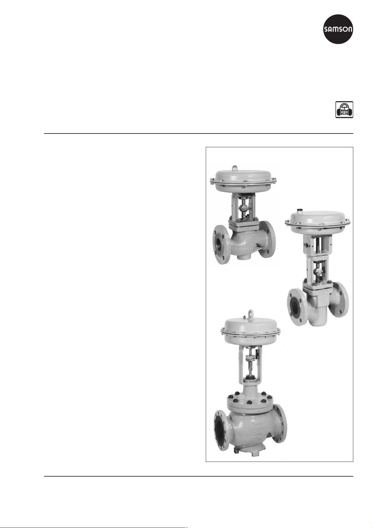
Series 240
Pneumatic Control Valve Type 3241-1 and Type 3241-7
Globe Valve Type 3241
Application
Control valve for process engineering and industrial
applications
Nominal size DN 15 to DN 300
Nominal pressure PN 10 to PN 40
Temperatures –196 to 450 °C
Type 3241 Globe Valve operated with:
Type 3271 Pneumatic Actuator (Type 3241-1 Control Valve)
•
or
Type 3277 PneumaticActuator(Type 3241-7 Control Valve)
•
Valve body made of:
Cast iron
•
Spheroidal graphite iron
•
Cast steel, cast stainless steel or cast cold-resisting steel
•
Forged steel or forged stainless steel
•
Special materials
•
Undivided valve bonnet up to DN 150
Valve plug with:
• Metal sealing
• Soft sealing
The modular design of the control valves allows them to be
equipped with various accessories:
Positioners, solenoid valves and other accessories according to
IEC 60534-6 and NAMUR recommendation. See Information
Sheet T 8350 EN for details.
Fig. 1 · Type 3241-1
DN 15 to 150
Versions
Standard version fortemperaturesranging from –10 to220°C
–
Type 3241-1 (Figs. 1 and 3) · DN 15 to 300
with Type 3271 Pneumatic Actuator (see T 8310-1/-2 EN)
–
Type 3241-7 (Fig. 2) · DN 15 to 150
with Type 3277 Pneumatic Actuator for integral positioner
attachment (see T 8310-1 EN)
Additional versions with:
–
Welding ends
–
Adjustable packing · See Information Sheet T 8000-1 EN
–
Flow divider or AC-1/AC-2 Trim for noise reduction · See
Data Sheets T 8081 EN and T 8082 EN
–
Perforated plug · On request
–
Valve plug with pressure balancing · See Technical data
–
Extension bonnet or bellows seal · See Technical data
–
Heating jacket · On request
–
Stainless steel actuator · See T 8310-1 EN
–
Additional handwheel · See Data Sheet T 8310-1/-2 EN
Associated Information Sheets T 8000-x EN
Associated Data Sheets for
Pneumatic Actuators T 8310-1/-2 EN
Fig. 2 · Type 3241-7
DN 15 to 80,
forged steel
Fig. 3 · Type 3241-1
Edition October 2011
DN 200
³
Data Sheet T 8015 EN
Type 3241 DWA · Version for PSA plants (pressure swing
–
adsorption) · See T 8012-1 EN and T 8015-1 EN
Typetested version · For application in heating systems (see
–
Data Sheet T 8016 EN), DIN/DVGW-tested version for gas
(see Data Sheet T 8020 EN), liquid fuels and liquefied
petroleum gas intheliquidphase (see Data SheetT8022 EN)
ANSI version · See Data Sheet T 8012 EN
–
Versions with dimensions according to Japanese Industry
–
Standard (JIS) · Details on request
Principle of operation
The process medium flows through the valve in the direction
indicated by the arrow. The position of the valve plug
determines the cross-sectional areabetweenthe seat and plug.
Fail-safe positions
Depending on howthe compression springs arearranged in the
actuator (see Data Sheets T 8310-1 EN and T 8310-2 EN for
details), the control valve has two different fail-safe positions
which become effective upon supply air failure:
Actuator stem extends (FA)
The actuator springs close the valve when the supply air fails.
Actuator stem retracts (FE)
The actuator springs open the valve when the supply air fails.
Differential pressures
Permissible differential pressures are listed in Information Sheet
T 8000-4 EN.
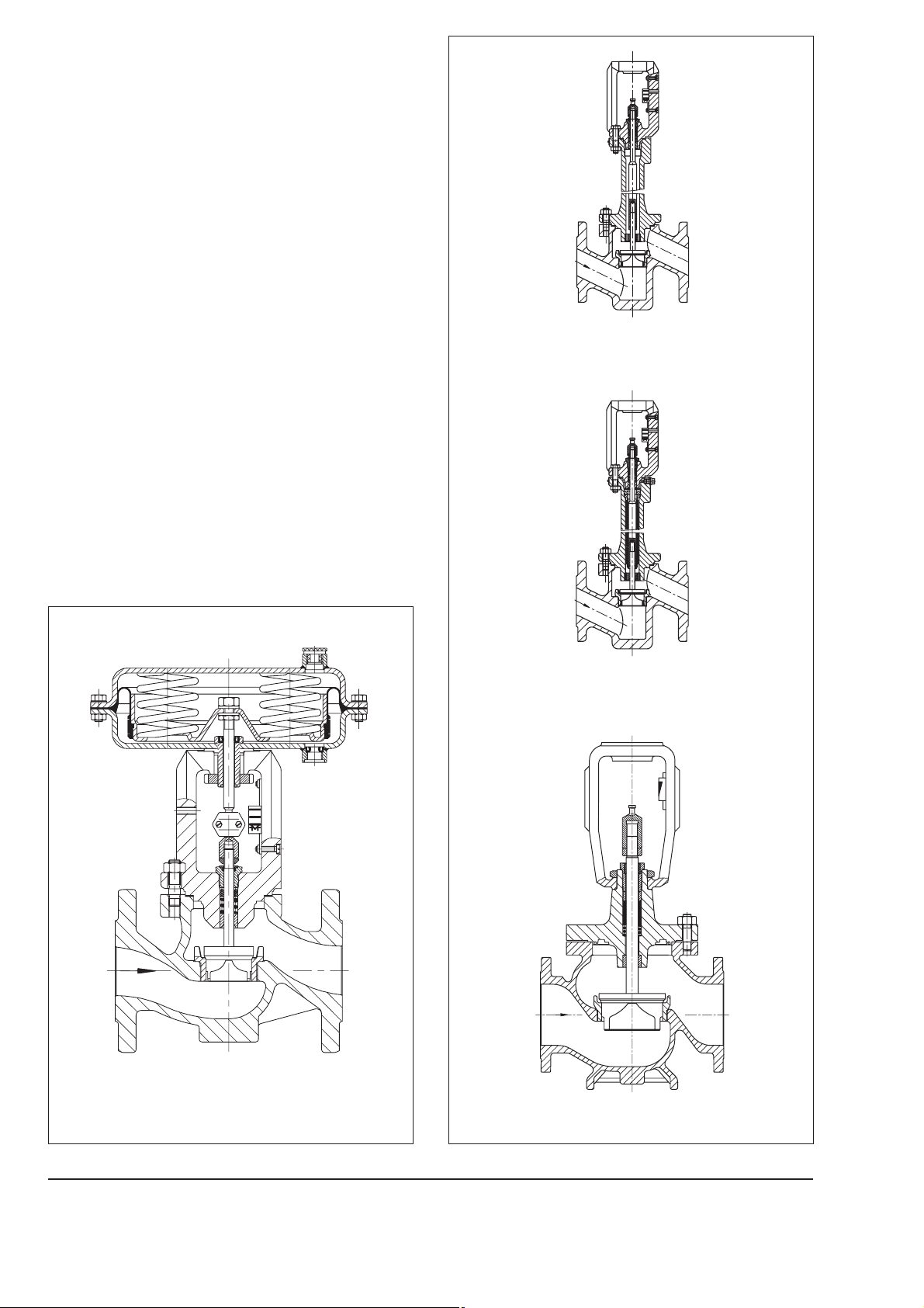
Fig. 5 · Type 3241 Valve, forged steel version
DN 15 to 80 with extension bonnet
Note
Figs. 4 to 6 show configuration examples.
Fig. 6 · Type 3241 Valve, forged steel version
DN 15 to 80 with metal bellows seal
Fig. 4 · Type 3241-1 Control Valve
DN 15 to 150 with Type 3271 Pneumatic Actuator
2
Fig. 7 · Type 3241 Control Valve, DN 200 to 300
T 8015 EN
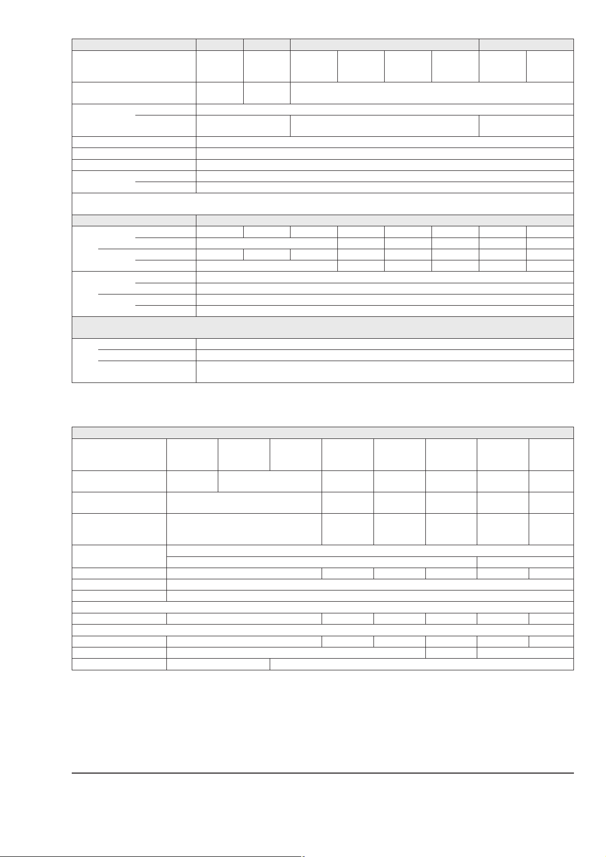
Table 1 · Technical data for Type 3241
Nominal size DN 15 to 250 15 to 150 15 to 300 15 · 25 · 40 · 50 · 80
Stainless
cast steel
1.4308
Forged steel
1.0460
Material
Nominal
pressure
Cast iron
EN-JL1040
PN
10 · 16 16 · 25 10 · 16 · 25 · 40
Sph. graphite
iron
EN-JS1049
Cast steel
1.0619
Stainless
cast steel
1.4408
Cast steel
1.6220
Flanges All DIN versions
End connections
Welding ends –
DIN EN 12627 Fig. 2 only for
DN 25, 40, 50, 80, 100, 150, 200, 250, 300
Seat/plug sealing Metal sealing · Soft sealing · High-performance metal sealing
Characteristic Equal percentage · Linear
Rangeability 50 : 1 for DN 15 to 50 · 30 : 1 for DN 65 to 150 · 50 : 1 for DN 200 and higher
Heating jacket
Up to DN 100 PN 25
DN 125 PN 16
³
Temperature ranges in °C · Permissible operating pressures acc. to pressure-temperature diagrams (see Information Sheet T 8000-2 EN)
Body without extension bonnet –10 to 220 °C
Short
–10…300 °C –10…350 °C –10…400 °C1)–50…450 °C –50...300 °C –50...300 °C –10…400 °C1)–50...450 °C
Long
Short
–10…300 °C –10…350 °C –10…400 °C1)–50…450 °C –50...300 °C –50...300 °C –10…400 °C1)–50…450 °C
Long
– –196...450 °C – –196...300°C – –196…450 °C
– –196...450 °C – –196...300 °C – –196…450 °C
Body
with
Valve
plug
Extension
bonnet
Bellows
seal
Standard
Balanced
Metal sealing –196 to 450 °C
Soft sealing –196 to 220 °C
with PTFE ring –50 to 220 °C · Lower temperatures on request
w. graphite ring 220 to 450 °C
Stainless
forged steel
1.4571
–
Leakage class according to IEC 60534-4
Metal sealing Standard: IV · High-performance metal sealing: V
Valve
plug
Balanced
1)
Down to –50 °C at p
Soft sealing VI
Metal sealing Standard: IV · With PTFE or graphite pressure-balancing ring
Special version: V · High-performance metal sealing (only with PTFE balancing ring) on request
75 % PN (acc. to AD W10)
£
max
Table 2 · Materials
Standard version
Forged
steel
1.0460
1.0460 1.4401
1.4006/
1.4008
1.4006
(1.4404)/
1.4008
Valve body
Valve bonnet
2)
Seat
2)
Plug
Plug sealing
1)
Cast iron
EN-JL1040
1.0460/
EN-JL1040
Sph. graphite
iron
EN-JS1049
1.0460/1.0619
Cast steel
1.0619
1.4006/1.4008
1.4006 (1.4404)/1.4008
Stainless
cast steel
1.4408
1.4408/
1.4401
1.4404/
1.4409
1.4404/
1.4409
Cast steel
1.6220
1.0566
1.6220
1.4006/
1.4008
1.4006
(1.4404)/
1.4008
Stainless
cast steel
1.4308
1.4308
1.4301
1.4301/
1.4308
1.4301/
1.4308
Sealing ring for soft sealing: PTFE with glass fiber
Sealing ring for balanced plug: PTFE with carbon or graphite ring –
Guide bushing 1.4104 1.4571 1.4571 1.4301 1.4104 1.4571
3)
Packing
V-ring packing PTFE with carbon · Spring: 1.4310
Body gasket Metal/graphite
Extension bonnet
1.0460 1.4401 1.0566 1.4301 1.0460 1.4401
Bellows seal
Intermediate piece 1.0460 1.4401 1.0566 1.4301 1.0460 1.4401
Metal bellows 1.4571
4)
1.4541 1.4571
Heating jacket – 1.4404
Stainless
forged steel
1.4571
1.4404/
1.4409
1.4404/
1.4409
4)
1)
Special materials for applications with sea water: 1.4538, duplex 1.4470; nickel-based alloy: 9.4610; other special materials on request.
2)
All seats and metal-seated plug also with Stellite facing; for£DN 100 plug up to seat bore 38 made of solid Stellite available.
3)
Other packings on request (refer to T 8000-1 EN)
4)
Other materials on request
3 T 8015 EN

Table 3 · KVScoefficients
Table 3a · Overview (with Flow Divider St I (K
K
VS
KVSI
KVSII
KVSIII
Seat Ø [mm] 3 6 12 24 31 38 48 63 80 63 80 100 110 130 125 150 200 250 300
Travel [mm] 15 30 60 120
0.1
0.16
0.4 0.63 1.0 1.6 2.5 4.0 6.3 10 16 25 40 60 80 63 100 160 200 260 250 360 630
0.25
– 1.45 2.2 3.6 5.7 9 14.5 22 36 54 72 57 90 144 180 234 225 320 560
– 8 13 20 32 48 63 50 80 125 160 210 200 290 500 800 –
– 7.5 – 20 30 – – 47 75 120 – – 190 270 480 750 –
I), St II (KVSII) or St III (KVSIII))
VS
1000*1500
900*1350
* Not available with valve body made of cast iron (EN-JL1040)
Terms for control valve sizing according to IEC 60534, Parts 2-1 and 2-2: F
= 0.95, XT= 0.75
L
Table 3b · Versions without flow divider · Areas highlighted in gray indicate versions also with pressure balancing
0.1
K
0.16
VS
DN
15 •••••••
20 ••••••••
25 •••••••••
32 •••••••••
40 ••••••••••
50 •••••••••••
65 • • • With 19 mm overtravel (not with bellows seal)
80 •••• •
100 •••
125 •••
150 ••• •
200 •• •••
250 •• ••••*
300 • •••••
0.4 0.63 1.0 1.6 2.5 4.0 6.3 10 16 25 40 60 80 63 100 160 200 260 250 360 630 1000 1500
0.25
*
*
Table 3c · Versions with Flow Divider St I (KVSI) · Areas highlighted in gray indicate versions also with pressure balancing
KVSI – 1.45 2.2 3.6 5.7 9 14.5 22 36 54 72 57 90 144 180 234 225 320 560 900 1350
DN
15 •••
20 •••
25 •••
32 •••
40 ••••
50 •••••
65 •••
80 ••••
100 •••
125 •••
150 ••• •
200 •••
250 ••••*
300 •••••
* DN 250 with KVSI = 900 not available with valve body made of cast iron (EN-JL1040)
4 T 8015 EN

Table 3d · Versions with Flow Divider St II (KVSII) · Areas highlighted in gray indicate versions also with pressure balancing
KVSII – 8 13 20 32 48 – 50 80 125 160 210 200 290 500 800 1200
DN
15
20
25
32 • •
40 •••
50 •••
65 •••
80 •••
100 •••
125 ••
150 ••• •
200 •• ••
250 •• •••
300 • ••••
Table 3e · Versions with Flow Divider St III (KVSIII) · Areas highlighted in gray indicate versions also with pressure balancing
KVSIII – 7.5 – 20 30 – – 47 75 120 – – 190 270 480 750 –
DN
15
20
25
32
40
50 •
65 • •
80 • •
100 •
125 •
150 •••
200 •• ••
250 ••• •••
300 • ••••
1)
Not with bellows seal
1)
5 T 8015 EN

Table 4 · Dimensions in mm for standard version of Type 3241-1 and Type 3241-7 with flanges or welding ends
250
250-
Valve
Length L
700 cm²
2)
H1
for
actuators
£
1400-60 cm²
1400-120 cm²
2800 cm²
H2 for
1)
Valve in DN 250-60 with 60 mm valve travel; DN 250-120 with 120 mm valve travel, not in cast iron
2)
H1 increases by 170 mm for valves with KVS250, 360 or 630 and 60 mm rated travel operating with overtravel.
3)
Version in PN 10/16: 148 mm
Cast steel 44 72 98 118 144
Forged steel 53 – 70 – 92 98 – 128 –
15 20 25 32 40 50 65 80 100 125 150 200
DN
130 150 160 180 200 230 290 310 350 400 480 600 730 730 730 850
mm
220 260 350 363 390 –
– 815 815 870 – 1185
– 902 902 955 1104 1334
– 902 902 955 1104 1334
3)
175 245 260 270 310 350
cast
iron
60
1)
250-
120
300
1)
2)
Actuator
Diaphragm
D
Æ
cm²
mm
H (700 cm² and larger
inc. lifting ring)
H3
1)
Type 3271
Type 3277 –
120 240 350 700 1400-60 1400-120 2800
168 240 280 390 530 534 770
70 62 82 200 287 490 630
110 190
610 650
H5 Type 3277 88 101 –
Thread
a
Type 3271
Type 3277 –
Type 3271
G ¼ (¼ NPT) G
M30x1.5
a2 Type 3277 – G
1)
Minimum clearance required to remove the actuator
3
3
(
NPT) G ¾ (¾ NPT) G 1 (1 NPT)
8
8
3
3
(
NPT) –
8
8
M60x1.5 M100x2
Table 5 · Weights in kg for standard version of Type 3241-1 and Type 3241-7
Valve
Weight without actuator
in kg
15 20 25 32 40 50 65 80 100 125 150 200
DN
5 6 7 11 12 15 24 30 42 80 120 396 468 608 872
250
cast iron
250
-60/
-120
300
Actuator
Type
3271
Type
3277
Without
handwheel
W. handwheel
80 mm travel
£
W. handwheel
160 mm travel
£
Without
handwheel
handwheel
cm²
With
120 240 350 700 1400-60 1400-120 2800
3 5 8 22 70 175 450
– 9 13 27 175 300 575
– 425 700
5 9 12 26
–
– 131731
6 T 8015 EN

Table 6a · Dimensions and weights for Type 3241 with extension bonnet or bellows seal DN 15 to 150 - without actuator
Nominal size
Height
H4
Weight
in kg
Short ext. bonnet
or bellows seal
Long ext. bonnet
or bellows seal
Short/with
bellows
Long/long with
bellows
15 20 25 32 40 50 65 80 100 125 150
DN
408 408 450 635 644 671
710 712 754 883 885 912
8 9 10 17 18 21 32 38 60 105 150
12 13 14 21 22 25 26 42 68 113 158
Table 6b · Dimensions and weights for Type 3241 with extension bonnet or bellows seal DN 200 to 300 - without actuator
Version with Extension bonnet Bellows seal
Actuator cm² 1400-60 1400-120 2800 1400-60 1400-120 2800
DN 200 1260
Height H4
in mm
DN 250
Travel =
60 mm
120 mm
DN 300 1683 1832 2055 2203
DN 200 440 485
Weight
in kg
DN 250
2)
DN 300 950 1020
1)
Also for DN 250 in cast iron (EN-JL1040)
2)
For cast iron (EN-JL1040) minus 140 kg
1494
–
1)
1579
1728
666 711
1345
1)
1579
1728
1467
1924
–
1)
2009
2158
1552
1)
2009
2158
Table 6c · Dimensions in mm for Type 3241 with heating jacket - Not for valves with body materials EN-JL1040 or EN-JS1049
Nominal size DN 25 40/50 80 100 150 200 to 300
a 110 140 180 200 265
b 1520355080
c 140 170 215 255 130
On request
d 190 190 230 320 355
Dimensions in mm
H3
H
H1
ØD
a
H5
a2
H2
L
Type 3241-1 · DN 15 to 150 Type 3241-1 · DN 200 to 300
Type 3241-7 · DN 15 to 150
7 T 8015 EN

Type 3241 with extension bonnet or metal bellows seal
Type 3241 with heating jacket
a
DN 15 to 150 DN 200 to 300
Ordering text
Globe valve Type 3241, DN … PN ...
Valve body material According to Table 2
End connections Flanges or welding ends
Seat and plug Metal sealing/soft sealing/
high-performance metal sealing
Characteristic Equal percentage or linear
Pneumatic actuator Type 3271 or Type 3277
Fail-safe position Valve CLOSED or OPEN
Process medium Density and temperature
Maximum flow rate in kg/h or m³/h
Pressure p
and p2in bar (absolute pressure)
1
Accessories Positioner and/or limit switch
Bellows seal version
with heating jacket
d
c
Flange DN 15 or 25, PN 25, DIN 2635
a
b
c
Specifications subject to change without notice.
SAMSON AG · MESS- UND REGELTECHNIK
Weismüllerstraße 3 · 60314 Frankfurt am Main · Germany
Phone: +49 69 4009-0 · Fax: +49 69 4009-1507
Internet: http://www.samson.de
T 8015 EN
2011-10
 Loading...