

Page 1
INSTRUCCIONES - USERS MANUAL - GEBRAUCHSANWEISUNG MODE D’EMPLOI - INSTRUZIONI PER L’USO - MANUAL DE INSTRUÇÕES
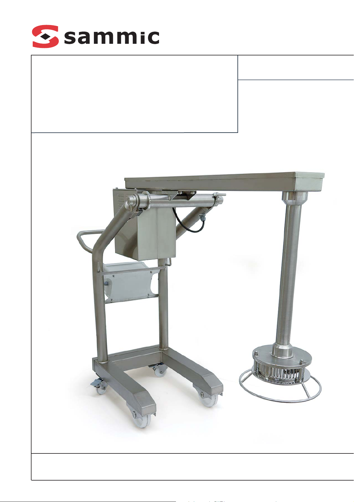
TRX-21 / TRX-22
Turbotrituradores
Turbo liquidisers
Turbopürierer
Turbo-broyeurs
Turbotrituratrici
Turbo-trituradores
Page 2
Cada máquina lleva las siguientes indicaciones:
- Nombre y dirección del fabricante: SAMMIC
S.L - Basarte 1 Azkoitia. Gipuzkoa (SPAIN).
- El número de serie se indica en la hoja de
garantía y en la declaración de conformidad.
MODELOS
Este manual describe la instalación, funcionamiento y mantenimiento de los turbo-trituradores TRX-21 (modelo una velocidad) y TRX-22
(modelo 2 velocidades). La referencia del
modelo y sus características se indican en la
placa de identificación colocada en la máquina.
Estos turbo-trituradores están diseñados y
fabricados de acuerdo con las directivas
Europeas:
· Directiva de máquinas 2006/42/CE
· Directiva de baja tensión 2006/95/CE
· Directiva de compatibilidad electromagnética
2004/108/CE
· Directivas de materiales de aluminio y plásticos alimentarios 89/109/CEE y 90/128/CEE.
· Norma mezcladora de brazo: UNE-EN 12854:
2004
· Índice de protección según la norma UNE-EN
60529: Mandos IP-55 y el resto de máquina
IP-23
INSTALACION
Para obtener las mejores prestaciones y una
buena conservación de la máquina, siga las
instrucciones contenidas en este manual.
MOVIMIENTO / EMPLAZAMIENTO
El turbo-triturador es una máquina móvil equipado con ruedas. Durante el desplazamiento
tomar las medidas necesarias para evitar golpes, vuelcos y situaciones peligrosas. Se recomienda realizar el desplazamiento en la posición de”transporte”.
A la hora de emplazar la máquina tener en
cuenta de dejarla sobre una superficie lisa y
con las ruedas traseras frenadas. También fijar
el brazo en una posición fija.
CONEXION ELECTRICA
Comprobar que las características eléctricas de la máquina coinciden con el de la
red.
TRX-21: 230-400V / 50 Hz / 3N (conectado a
400V/3N); 220-380V / 60 Hz / 3N (conectado a
220V/3). Para cambiar de voltaje seguir las indicaciones del esquema eléctrico.
TRX-22: 400V / 50 Hz / 3N; 220V / 60 Hz / 3.
NOTA: La TRX-22 es mono-tensión y no es
posible realizar ningún tipo de cambio de voltaje.
Preparar una toma de corriente mural, que sea
siempre accesible, con interruptor general de
seccionamiento, y con protección diferencial y
magneto-térmica de 4P de 10 A con su clavija
correspondiente.
Sentido de giro: La cuchilla giratoria (19) debe
girar en sentido anti horario mirando desde la
parte superior de la herramienta. Si el giro de la
cuchilla giratoria (19) es en sentido horario,
invertirlo intercambiando dos fases en el cable
de alimentación.
CARACTERÍSTICAS DEL CABLE
Los turbo-trituradores se suministran con un
cable eléctrico de 10 m de largo, con recubrimiento termo plástico.
ATENCION: ES OBLIGATORIA LA CONEXION
A TIERRA. PELIGRO DE ELECTROCUCION.
El hilo de toma-tierra de la máquina es el de
color amarillo-verde.
FUNCIONES DEL CONTROL: (Figura1)
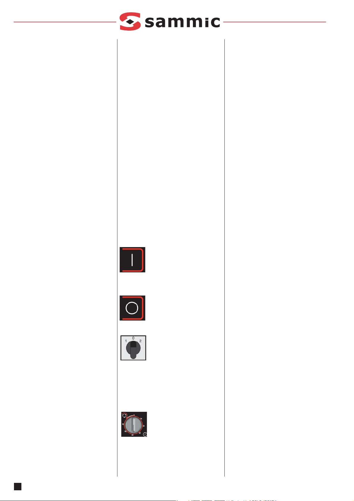
Pulsador de “Marcha” (A)
La pulsación de este botón arranca el motor si
el brazo está dentro del área de trabajo y el
temporizador en posición.
Pulsador de “Parada” (B)
La pulsación de este botón para el motor.
Selector de velocidad (C). Solo
TRX-22
Posición 0: Para el motor, pero la parada total
se tiene que dar por el pulsador de “Parada”.
Nunca dejar la máquina en “Posición 0” sin pulsar el botón de “parada”.
Posición 1 velocidad baja.
Posición 2 velocidad alta.
Temporizador (D)
Posición central: No permite el funcionamiento
de la máquina.
Giro horario: Temporización de 0 a 60 minutos.
Giro anti horario: Funcionamiento continuo sin
temporizador.
PUESTA EN MARCHA
ATENCION:
Antes de utilizar por primera vez la máquina,
limpiar la zona de contacto con alimentos, la
cuchilla giratoria (19) y la cuchilla fija(18)
con agua jabonosa (templada), aclarar y
dejarla secar.
La cuchilla giratoria (19) y la fija (18) están provistas de áreas muy afiladas, por tanto hay que
manipularlas cuidadosamente.
GIRO Y FRENADO DEL BRAZO:
El brazo (4) dispone de un sistema de frenado,
accionado por medio de palanca (8) para bloquear y mantener el mismo en la posición deseada. Con el freno liberado es posible girar el
brazo con facilidad. Para el bloqueo del brazo
girar la palanca de frenado (8) en sentido horario y apretarlo con fuerza hasta que el brazo se
bloquee. Para liberarlo girarlo en el sentido
opuesto hasta llegar al tope (6).
DIFERENTES POSICIONES DEL BRAZO:
Posición de transporte: figura2
Posición cambio de herramienta: figura3
Posición de almacenaje: figura 4
Zona de trabajo: figura 5
MONTAJE Y DESMONTAJE DE HERRAMIENTAS (FIGURA 6)
Descripción del proceso de desmontaje y montaje, de protector (17), Cuchilla giratoria (19) y
Cuchilla fija (18). Estas operaciones se realizan
en las maniobras de limpieza o cambio de
herramientas.
Atención: Antes de cualquier intervención para
el montaje de herramientas, limpieza, revisión
o reparación de los turbo trituradores es obligatorio desconectar la máquina de la red.
Los pasos para la colocación de herramientas
se describen a continuación. En la sección
“LIMPIEZA” el orden de los pasos, son inversos
a los descritos en este apartado.
- Desbloquear el freno con la palanca (8), y
girar el brazo (4) empujando la parte del
motor hacia abajo hasta que la herramienta
quede accesible. Posición cambio de herramienta figura2
- Insertar la cuchilla giratoria (19) en el eje
estriado y mantenerlo hasta atornillar en el eje
estriado el tronillo de fijación (20) con la otra
mano.
- Bloquear la cuchilla giratoria (19) utilizando la
2
ES
Page 3

3
ES
llave suministrada y apretar el tornillo de fijación (20) con la otra llave.
- Colocar la cuchilla fija (18) sobre el protector
de cuchillas (17) de manera que las pestañas
de la cuchilla fija se posicionen al introducirlo
en su alojamiento guía.
- Introducir el conjunto de cuchilla fija + soporte cuchilla (18+17) fija en los agujeros del
brazo (2) y apretar las fijaciones (21) hasta
que el soporte (17) quede fijo.
- Apretar los 3 tornillos (21) de la caña sumergible (2) con la llave suministrada en el equipo.
ÁNGULOS O POSICIONES DE TRABAJO:
El ángulo o la posición de trabajo viene determinada por el conjunto leva-micro (16) situado
en el soporte brazo. Si se gira demasiado el
brazo (4) y se sale del área de trabajo permitido, el micro para el turbo-triturador. Es necesario girar el brazo hasta la zona de trabajo para
que el micro (16) actúe y al pulsar marcha se
pueda arrancar de nuevo el turbo-triturador.
TIPOS DE HERRAMIENTAS
Cuchilla giratoria. Disco 4 filos absorción reforzada. (19)
Cuchilla fija de 42 dientes Para triturado fino
(18).
Cuchilla fija de 30 dientes Para triturado intermedio (18).
Cuchilla fija de 21 dientes Para triturado de
productos fibrosos (18).
LIMPIEZA
ATENCION: Desconectar el turbo-triturador
de la red antes de cualquier manipulación
en su interior.
La cuchilla giratoria de corte (19) y cuchilla fija
(18) están provistos de cuchillas muy afiladas,
por tanto hay que manipularlas cuidadosamente.
Todos los elementos de la cortadora que están
en contacto con los alimentos se deben limpiar
inmediatamente después de su utilización, con
agua caliente y un detergente admitido en alimentación. Después aclarar con abundante
agua caliente y desinfectar con un paño suave
impregnado en alcohol etílico (90 º).
La cuchilla giratoria (19), Cuchilla fija (18) y el
soporte cuchilla fija (17) es posible introducirlos
a un lavavajillas para su limpieza y desinfección.
Para ello:
- Desbloquear el freno (8), y girar el brazo (4)
figura 7 hasta la posición “cambio de herra-
mienta”. S/figura 3
- Con la llave aflojar los 3 tornillos del soporte
cuchilla fija (2). Retirar el conjunto cuchilla fija
(18) + soporte cuchilla fija (17) del brazo.
- Separar la Cuchilla fija (18) del protector de
cuchilla (17) y lavar las dos piezas a mano o
en lavavajillas.
- Con la llave aflojar el tornillo de fijación (20) y
soltarlo. El cuchilla giratoria (19) sale hacia
abajo del eje estriado. Lavar esta pieza a
mano o en lavavajillas.
- Limpiar el resto de brazo (2) y máquina con
agua caliente y un detergente admitido en alimentación. Después aclarar con abundante
agua caliente y desinfectar con un paño suave
impregnado en alcohol etílico (90 º).
El exterior de la máquina NO SE DEBE limpiar
con un chorro directo de agua. NO SE DEBEN
utilizar detergentes abrasivos (aguafuerte, lejía
concentrada etc...) ni estropajos o rasquetas
que contengan acero común, pueden causar la
oxidación de la máquina.
MANTENIMIENTO
PRECAUCIONES IMPORTANTES
- Antes de cualquier intervención para la
limpieza, revisión o reparación del turbotriturador es obligatorio desconectar la
máquina de la red.
- No introducir NUNCA la mano ni cualquier
utensilio a la zona de la herramienta (1) fig. 7
durante el triturado, a fin de evitar accidentes
o el deterioro de las cuchillas.
- Verificar periódicamente el funcionamiento de
las seguridades. Comprobar que el conjunto
micro-leva (16) que controla el giro funciona.
En caso de detectar alguna anomalía llamar al
servicio técnico reconocido por SAMMIC.
- Verificar periódicamente el estado de la
correa. Retirar la tapa (3) y verificar que esta
tensado correctamente.
- Verificar anualmente o cada 400 horas de uso
el estado del retén del eje de arrastre de la
cuchilla giratoria para preservar la estanqueidad de esta zona al ser una pieza de desgaste. Cada vez que se suelte el eje de arrastre
para mantenimiento, se recomienda colocar
un retén nuevo.
- Limpiar el turbo-triturador después de cada
uso tal y como se ha descrito con anterioridad.
- Si el cable de alimentación se deteriora y es
preciso instalar uno nuevo, dicho recambio
sólo podrá ser realizado por un servicio técnico reconocido por SAMMIC.
- Nivel de ruido de la máquina, en marcha, colo-
cada a 1,6 m de altura y 1 m de distancia, inferior a 70 dB(A). Ruido de fondo: 32 dB(A).
INCIDENCIAS DE FUNCIONAMIENTO
• Estando el brazo en la posición de trabajo,
pulsando marcha el turbo-triturador no arranca, comprobar:
- El turbo-triturador está conectado a red
correctamente.
- Con el turbo-triturador desconectado verificar el estado de los fusibles. Se encuentran
dentro de la caja eléctrica (12).
- Verificar que el micro (16) del brazo funciona correctamente. También verificar que la
leva (16) de acero inoxidable está fijada
correctamente en su posición original.
- Verificar que el temporizador no está en la
posición central y funciona correctamente.
• El turbo-triturador estaba en marcha y se ha
parado sin pulsar ningún botón.
- Si se nota la carcasa del motor (5) está muy
caliente, puede que el térmico del motor
haya actuado. Esperar unos 30 minutos
hasta que el motor se enfríe y probar de
nuevo.
- Puede que el brazo (4) haya girado por no
estar bien fijado y ha salido de la zona de
trabajo.
- El temporizador ha realizado su función y
ha parado la máquina.
• El motor gira pero la cuchilla giratoria no:
- Verificar sistema de transmisión: el estado
de la correa y verificar chavetas y poleas.
OTRAS OBSERVACIONES IMPORTANTES
Este aparato no está destinado para ser usado
por personas (incluidos niños) cuyas capacidades físicas, sensoriales o mentales estén reducidas, o carezcan de experiencia o conocimiento, salvo si han tenido supervisión o instrucciones relativas al uso del aparato por una persona responsable de su seguridad.
El turbo triturador es de uso vigilado no dejar
nuca la máquina en marcha sin que nadie este
al cargo de ella.
La TRX-22 es un turbo-triturador de 2 velocidades. Usar la velocidad baja de manera intermitente. Marcha 30 minutos con descansos de 10
minutos.
Ruido
Ruido en
Vacío
En Carga (introdu-
cido en agua)
Velocidad mínima
de trabajo
60 dB
66 dB
Velocidad máxima
de trabajo
63 dB
≤ 80 dB
Page 4
Each machine is identified as follows:
-Name and address of the manufacturer:
SAMMIC S.L - Basarte 1 Azkoitia. Gipuzkoa
(SPAIN)
-The serial number is printed on the Guarantee
Card and in the Declaration of Conformity.
MODELS
This manual describes the installation, operation and maintenance of the TRX-21 (1-speed
model) and TRX-22 (2-speed model) turbo liquidisers. The model reference and technical data
appear on the name plate attached to the
machine. These turbo liquidisers have been
designed and manufactured in accordance with
the following European directives:
· Machinery Directive 2006/42/EC.
· Low Voltage Directive 2006/95/EC.
· Electromagnetic Compatibility Directive
2004/108/EC.
· Directives 89/109/EEC and 90/128/EEC on
aluminium and plastic materials and articles in
contact with food.
· Arm mixers standard: UNE-EN 12854: 2004
· Protection level according to standard UNE-
EN 60529: Controls IP-55 and rest of the
machine IP-23
INSTALLATION
For optimum service and maintenance, please
follow these instructions.
MOVEMENT / INSTALLATION SITE
The turbo-liquisider is a mobile machine equipped with wheels. When being moved take all
necessary measures to avoid blows, falls and
dangerous situations. Movement is recommended in the ”transport” position.
When installing the machine make sure it is left
on a flat surface and with the rear wheels blocked. Also set the arm in a fixed position.
ELECTRICAL CONNECTION
Check that the machine's electrical characteristics match the mains power supply.
TRX-21: 230-400V / 50 Hz / 3N (connected to
400V/3N); 220-380V / 60 Hz / 3N (connected to
220V/3). To change the voltage, refer to the
electrical diagram.
TRX-22: 400V / 50 Hz / 3N; 220V / 60 Hz / 3.
NOTE: The TRX-22 is single-voltage and it is
not possible to carry out any voltage change.
Prepare a wall-mounted socket that is always
accessible, with a general cut-off switch and a
residual current and 4P, 10 A circuit breaker,
with its corresponding plug.
Rotation direction: The rotating blade (19) must
rotate anti-clockwise when looking from above
the tool. If the blade (19) rotates clockwise, to
reverse it swap two phases in the power cable.
POWER CABLE CHARACTERISTICS
The turbo-liquidisers are supplied with a 10 m
thermoplastic-sheathed power cable.
ATTENTION: THE EARTH CONNECTION IS
OBLIGATORY. DANGER OF ELECTROCUTION. The machine's earth wire is yellowgreen.
CONTROL FUNCTIONS: (Figure1)
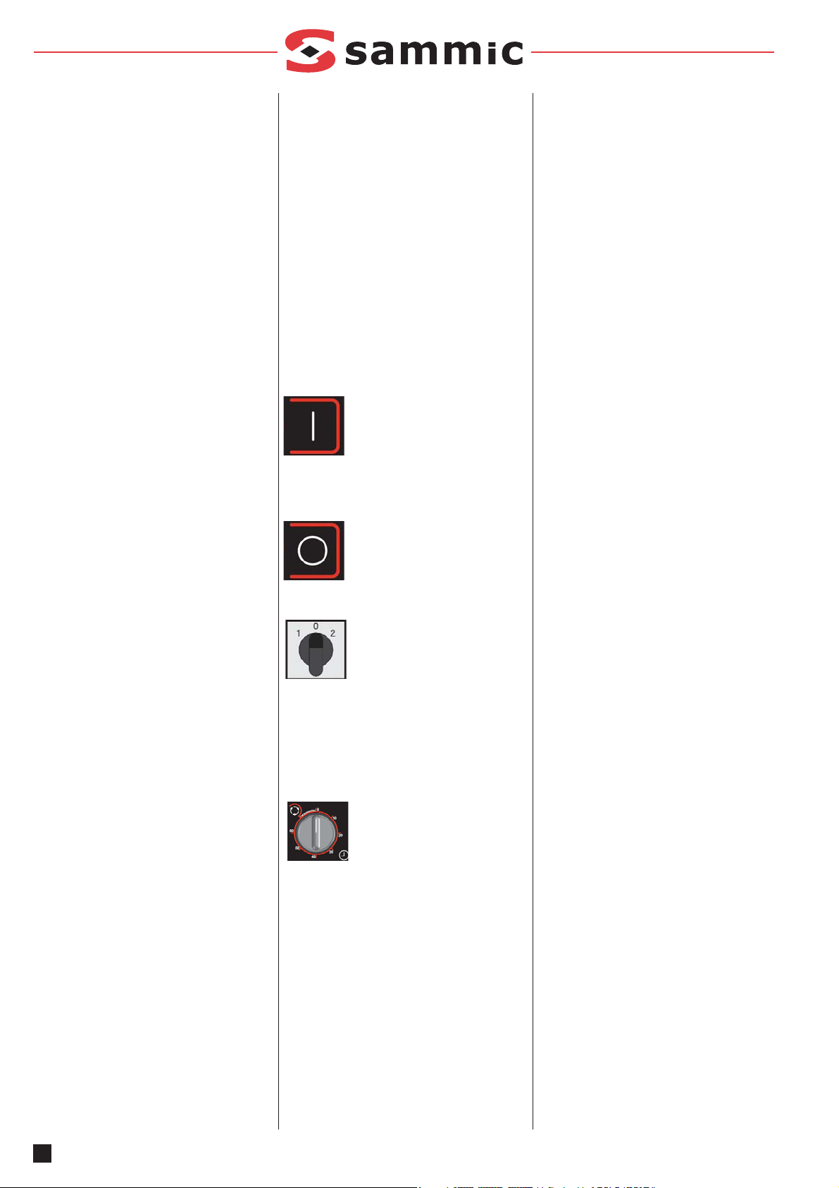
“Start” button (A)
Pressing this button starts the motor if the arm
is within the work area and the timer is in position.
“Stop” button (B)
Pressing this button stops the motor.
Speed selector (C). Only TRX-22
Position 0: Stops the motor, but it must be completely stopped with the “Stop” button. Never
leave the machine at “Position 0” without pressing the “stop” button.
Position 1 low speed.
Position 2 high speed.
Timer (D).
Central position: Does not allow operation of
the machine.
Clockwise rotation: Timing from 0 to 60 minutes.
Anti-clockwise rotation: Continuous operation
without timer.
START-UP
WARNING:
Before using the machine for the first time,
clean the area in contact with food, the rotating blade (19) and the fixed blade (18) with
(lukewarm) soapy water, rinse and leave to
dry.
Handle the rotating blade (19) and the fixed one
(18) very carefully because they have very
sharp edges.
ARM ROTATION AND BRAKING:
The arm (4) has a braking system, activated by
a lever (8) to block and and keep it at the desired position. With the brake released the arm is
easily rotated. To block the arm turn the brake
lever (8) clockwise and tighten it firmly until the
arm is blocked. To release it turn it in the opposite direction until the limit is reached (6).
DIFFERENT POSITIONS OF THE ARM:
Transport position: figure2
Tool change position: figure3
Storage position: figure 4
Work area: figure 5
ASSEMBLY AND DISASSEMBLY OF TOOLS
(FIGURE 6)
Description of the disassembly and assembly
process of the protector (17), Rotating blade
(19) and Fixed blade (18). These operations are
carried out during the cleaning or tool changing
processes.
Attention: Before undertaking any tool
assembly, cleaning, inspection or repair
work on the turbo liquidisers, the machine
must be unplugged from the mains.
The steps to fit the tools are described below. In
the “CLEANING” section the order of the steps
is the reverse of those described in this section.
- Unblock the brake with the lever (8), and rotate the arm (4) pushing the motor part downwards until the tool is accessible. Tool change
position figure2
- Insert the rotating blade (19) on the grooved
shaft and hold it until the fixing screw (20) is
screwed to the grooved shaft with the other
hand.
- Lock the rotating blade (19) using the wrench
supplied and tighten the fixing screw (20) with
the other wrench.
- Place the fixed blade (18) on the blade protector (17) so that the tabs of the fixed blade are
in position when inserting it in its slot.
- Insert the fixed blade + fixed blade support
assembly (18+17) in the arm holes (2) and
tighten the fasteners (21) until the support (17)
is fixed.
- Tighten the 3 screws (21) of the submersible
rod (2) with the wrench supplied with the
machine.
4
EN
Page 5

WORK ANGLES OR POSITIONS:
The work angle or position is determined by the
micro-lever assembly (16) located on the arm
support. If the arm (4) is rotated too much and
exits the work area allowed permitted, the
micro-lever stops the turbo-liquidiser. It is
necessary to rotate the arm to the work area
son that the micro (16) is activated and when
pressing start the turbo-liquidiser can be turned
on again.
TYPES OF TOOLS
Rotating blade. Disc 4 edges reinforced absorption. (19)
Fixed blade with 42 teeth For fine liquidising
(18).
Fixed blade with 30 teeth For intermediate
liquidising (18).
Fixed blade with 21 teeth For liquidising fibrous
products (18).
CLEANING
ATTENTION: Disconnect the turbo-liquidiser
from the mains before handing any internal
components.
Handle the rotating cutting blade (19) and the
fixed blade (18) very carefully because they
have very sharp edges.
Any components in contact with the food must
be cleaned immediately after use, using hot
water and a food-safe detergent. Then rinse
with plenty of hot water and disinfect using an
ethyl alcohol-soaked cloth (90 º).
It is possible to clean and disinfect the rotating
blade (19), the Fixed blade (18) and the fixed
blade support (17) in a dishwasher.
To do so:
- Release the brake (8), and turn the arm (4)
figure 7 to the “tool change” position. s/figure
3
- With the wrench loosen the 3 screws of the
fixed blade support (2). Remove the fixed
blade (18) + fixed blade support (17) assembly
from the arm.
- Separate the Fixed blade (18) from the blade
protector (17) and clean both parts by hand or
in a dishwasher.
- Loosen the fastening screw (20) with the
wrench and remove it. The rotating blade (19)
comes off the bottom of the grooved shaft.
Clean this part by hand or in a dishwasher.
- Clean the rest of the arm (2) and machine with
hot water and a food-safe detergent. Then
rinse with plenty of hot water and disinfect
using an ethyl alcohol-soaked cloth (90 º).
NEVER power clean. DO NOT use abrasive
detergents (nitric acid, neat bleach, etc.) or
stainless steel scourers or scrubbers as they
could cause rusting.
MAINTENANCE
CAUTION
- Before undertaking any cleaning, inspection or repair work on the turbo-liquidiser,
the machine must be unplugged from the
mains.
- NEVER insert your hand nor any other utensil
in the tool area (1) fig. 7 during the liquidising,
in order to avoid accidents or the deterioration
of the blades.
- Regularly check that the machine safety devices are working. Check that the micro-lever
(16) that controls rotation works. If you detect
any anomaly, call the SAMMIC authorised
technical service.
- Regularly check the state of the belt. Remove
the cover (3) and verify that it has the correct
tension.
- Regularly inspect the state of the seal of the
rotating blade drive shaft to preserve the leaktightness of this area. Every time you loosen
the trailing axle for maintenance you should fit
a new seal.
- Clean the turbo-liquidiser after every use, as
described above.
- Only a SAMMIC authorised technical service
can replace the power cable if this is damaged.
- Machine noise level, while running, at a height
of 1.6 m and a distance of 1 m, less than 70
dB(A). Background noise: 32 dB(A).
TROUBLESHOOTING
• When the arm is in the work position, when
the start button is pressed the turbo-liquidiser
will not start, check that:
- The turbo-liquidiser is correctly connected to
the mains.
- With the turbo-liquidiser disconnected verify
the state of the fuses. They are inside the
electrical box (12).
- Check that the micro-lever (16) of the arm
functions correctly. Also check that the stain-
less steel lever (16) is correctly set to its original position.
- Check that the timer is not in the central
position and that it works correctly.
• The turbo-liquidiser was on and stopped
without pressing any button.
- If you notice that the motor casing (5) is very
hot, maybe the thermal relay of the motor
has been activated. Wait for about 30 minutes until the motor has cooled and try again.
- The arm (4) may have rotated due to not
being properly fixed and has exited the work
area.
- The timer has fulfilled its function and has
stopped the machine.
• The motor turns but not the rotating blade:
- Check the transmission system: the state of
the belt and check pins and pulleys.
OTHER IMPORTANT INFORMATION
This machine is not designed for use by people
(including children) with reduced physical, sensory or mental capabilities or lacking the necessary experience or knowledge, unless they
have received supervision or instructions from a
health and safety expert.
The turbo-liquidiser must not be left running
unsupervised.
The TRX-22 is a 2-speed turbo-liquidiser. Use
the low speed intermittently. On for 30 minutes
with 10-minute breaks
.
5
EN
Noise
Noise when
empty
Loaded (immer-
sed in water)
Minimum opera-
tion speed
60 dB
66 dB
Maximum opera-
tion speed
63 dB
≤ 80 dB
Page 6
Jede Maschine ist mit folgenden Angaben
gekennzeichnet:
- Name und Anschrift des Herstellers: SAMMIC
S.L – Basarte 1 Azkoitia. Gipuzkoa (SPANIEN)
- Seriennummer auf dem Garantieschein und in
der Konformitätserklärung.
MODELLE
In diesem Handbuch werden die Installation,
der Betrieb und die Wartung der TurboPürierstäbe TRX-21 (Modell mit einer
Geschwindigkeit) und TRX-22 (Modell mit zwei
Geschwindigkeiten) beschrieben. Die Referenz
des Modells und seine Merkmale sind auf dem
Typenschild der Maschine angegeben. Diese
Turbo-Pürierstäbe wurden im Einklang mit folgenden EU-Richtlinien konzipiert und hergestellt:
· Richtlinie Maschinen: 2006/42/EG
· Richtlinie Niederspannung: 2006/95/EG
· Richtlinie elektromagnetische Verträglichkeit:
2004/108/EG
· Richtlinien Aluminium und Kunststoffe, die mit
Nahrungsmittel in Berührung kommen
89/109/EG und 90/128/EG.
· Bestimmung Stabmixer: UNE-EN 12854: 2004
· Schutzklasse gemäß der Norm UNE-EN
60529: Bedienelemente IP-55, übrige Teile
des Geräts IP-23
MONTAGE
Um die bestmögliche Leistung und eine lange
Lebensdauer der Maschine sicherzustellen,
befolgen Sie bitte genau die Hinweise in dieser
Betriebsanleitung.
BEWEGUNG/AUFSTELLUNG
Der Turbo-Pürierstab ist ein mit Rädern ausgestattetes mobiles Gerät. Treffen Sie während der
Bewegung die erforderlichen Maßnahmen, um
Stöße, Stürze und gefährliche Situationen zu
vermeiden. Es wird empfohlen, Bewegungen in
der „Transport“-Position durchzuführen.
Beachten Sie bei der Aufstellung, dass das
Gerät bei blockierten Hinterrädern auf eine flache Ebene gestellt werden muss. Bringen Sie
auch den Stab in eine feste Position.
ELEKTRISCHER ANSCHLUSS
Vergewissern Sie sich, dass die elektrischen
Anforderungen des Geräts von den
Eigenschaften des Netzes erfüllt werden.
TRX-21: 230-400 V/50 Hz/3 N (angeschlossen
an 400 V/3 N); 220-380 V/ 60 Hz/ 3 N (angeschlossen an 220 V/3). Nehmen Sie den
Spannungswechsel wie im elektrischen
Schaltschema angezeigt vor.
TRX-22: 400 V/50 Hz/3N; 220 V/60 Hz/ 3. HINWEIS: Der TRX-22 weist eine Spannung auf,
und es ist nicht möglich, einen
Spannungswechsel vorzunehmen.
Sehen Sie eine stets zugängliche
Wandsteckdose mit Abschnittshauptschalter,
Fehlerstromschutz und thermomagnetischem
Schutzschalter mit 4P, 10 A sowie den entsprechenden Stecker vor.
Drehrichtung: Das Drehmesser (19) muss sich
gegen den Uhrzeigersinn drehen (Blickrichtung
von oben). Wenn sich das Drehmesser (19) im
Uhrzeigersinn dreht, drehen Sie es um, indem
Sie die beiden Phasen im Stromkabel vertauschen.
EIGENSCHAFTEN DES KABELS
Die Turbo-Pürierstäbe werden mit einem
Stromkabel mit einer Länge von 10 Metern mit
thermoplastischer Beschichtung geliefert.
ACHTUNG: DER ERDANSCHLUSS IST
PFLICHT. GEFAHR EINES STROMSCHLAGS.
Das Erdungskabel des Geräts ist gelb-grün.
STEUERFUNKTIONEN: (Abbildung 1)
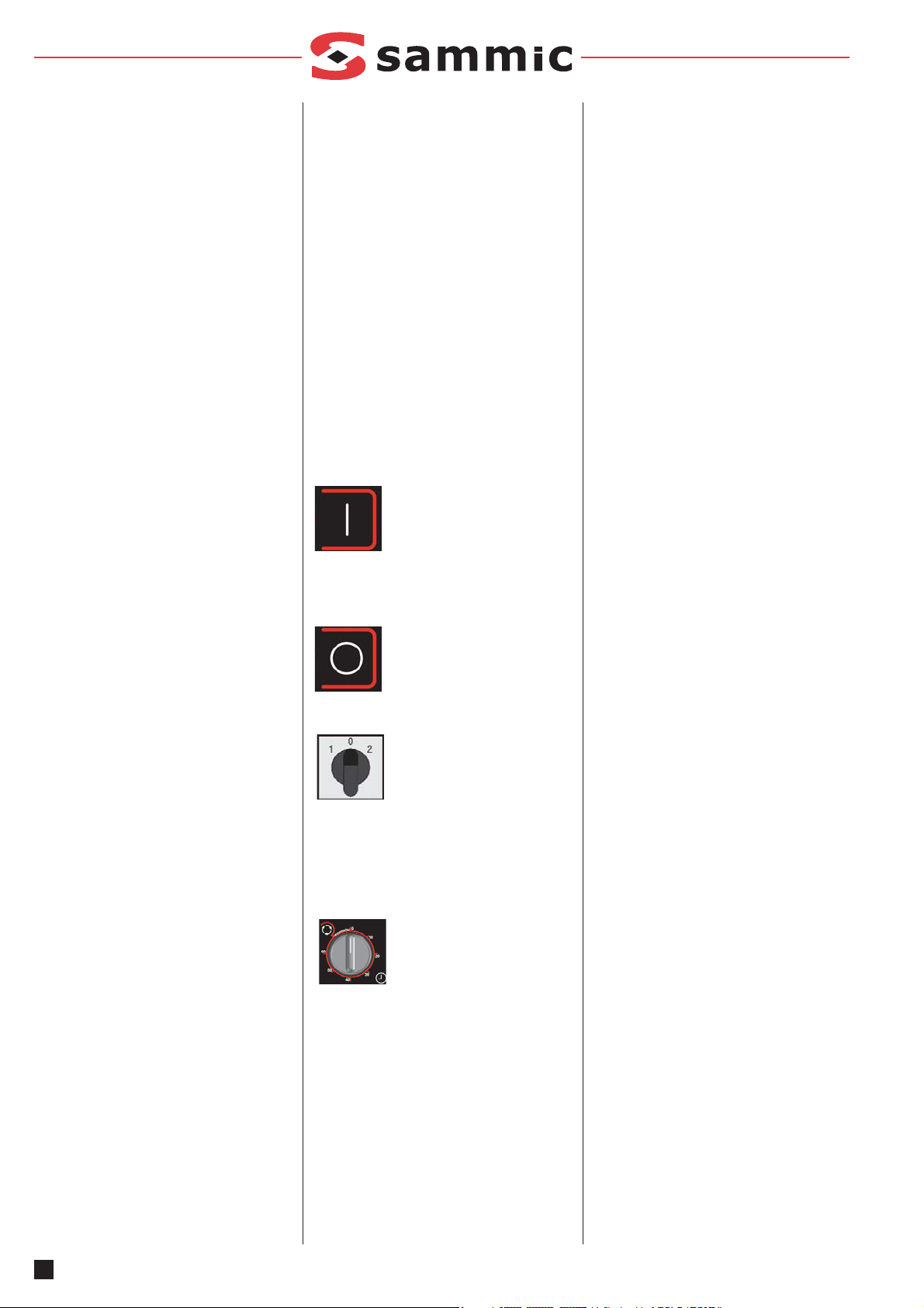
Starttaste (A).
Wenn Sie diese Taste betätigen,
startet der Motor, sobald sich der Stab innerhalb
des Arbeitsbereichs befindet und der
Zeitschalter in Position ist.
Stopptaste (B).
Wenn Sie diese Taste betätigen,
hält der Motor an.
Geschwindigkeitsregler (C). Nur
bei TRX-22
Position 0: Der Motor wird ange-
halten, doch um ihn vollständig
zum Stillstand zu bringen, muss die Stopptaste
gedrückt werden. Lassen Sie das Gerät niemals in der Position 0, ohne die Stopptaste
gedrückt zu haben.
Position 1 niedrige Geschwindigkeit.
Position 2 hohe Geschwindigkeit.
Zeitschalter (D).
Mittlere Position: Verhindert den
Betrieb des Geräts.
Drehung im Uhrzeigersinn: Zeitschaltung von 0
bis 60 Minuten.
Drehung gegen den Uhrzeigersinn:
Fortlaufender Betrieb ohne Zeitschaltung.
INBETRIEBNAHME
ACHTUNG:
Vor der erstmaligen Inbetriebnahme des
Geräts den Bereich, der in Kontakt mit
Lebensmitteln kommt, das Drehmesser (19)
und das feste Messer (18) mit Seifenlauge
(lauwarm) reinigen, abspülen und trocknen
lassen.
Das Drehmesser (19) und das feste Messer
(18) weisen äußerst scharfe Bereiche auf, weshalb diese mit höchster Vorsicht zu behandeln
sind.
DREHEN UND ANHALTEN DES STABES:
Der Stab (4) ist mit einem Bremssystem ausgestattet, das mit einem Hebel (8) aktiviert werden kann, um den Stab zu blockieren und in der
gewünschten Position zu halten. Bei gelöster
Bremse kann der Stab einfach gedreht werden.
Um den Stab zu blockieren, drehen Sie den
Bremshebel (8) im Uhrzeigersinn und ziehen
diesen kräftig fest, bis der Stab blockiert ist. Um
ihn zu lösen, drehen Sie den Hebel bis zum
Anschlag (6) in die entgegengesetzte Richtung
.
UNTERSCHIEDLICHE POSITIONEN DES
STABES:
Position beim Transport: Abbildung 2
Position beim Werkzeugwechsel: Abbildung 3
Position bei der Lagerung: Abbildung 4
Arbeitsbereich: Abbildung 5
MONTAGE UND ABMONTAGE DER WERKZEUGE (ABBILDUNG 6)
Beschreibung der Montage und Abmontage der
Schutzvorrichtung (17), des Drehmessers (19)
und des festen Messers (18). Diese Arbeiten
werden bei Reinigungsarbeiten oder beim
Werkzeugwechsel durchgeführt.
Achtung: Vor jedem Eingriff zwecks
Werkzeugmontage, Reinigung, Überprüfung
oder Reparatur der Turbo-Pürierstäbe muss
das Gerät unbedingt vom Stromnetz genommen werden.
Die Schritte zum Einsetzen der Werkzeuge
werden im Folgenden beschrieben. Im
Abschnitt „REINIGUNG“ sind diese Schritte in
umgekehrter Reihenfolge angegeben.
- Lösen Sie die Bremse mit dem Hebel (8) und
drehen Sie den Stab (4), indem Sie den
Motorbereich nach unten drücken, bis Sie das
Werkzeug erreichen können. Position beim
Werkzeugwechsel: Abbildung 2
- Setzen Sie das Drehmesser (19) in die
Nutwelle ein und halten Sie es, während Sie
mit der anderen Hand die
Befestigungsschraube (20) in die Nutwelle
schrauben.
- Blockieren Sie das Drehmesser (19) mit dem
im Lieferumfang inbegriffenen
Schraubenschlüssel und ziehen Sie die
Befestigungsschraube (20) mit dem anderen
Schraubenschlüssel fest.
- Setzen Sie das feste Messer (18) auf den
Messerschutz (17) auf, sodass der Flansch
des festen Messers in die entsprechende
Schiene eingeführt werden kann.
- Fügen Sie die Einheit des festen Messers und
dessen Halterung in die Öffnungen des
Stabes (2) ein und ziehen Sie die
Befestigungen (21) fest, bis die Halterung (17)
fest ist.
6
DE
Page 7

- Ziehen Sie die drei Schrauben (21) des
Tauchrohrs (2) mit dem im Lieferumfang inbegriffenen Schraubenschlüssel fest.
WINKEL ODER ARBEITSPOSITIONEN:
Der Winkel oder die Arbeitsposition wird über
den Mikro-Hebel (16) auf der Stabhalterung festgelegt. Wenn der Stab (4) übermäßig gedreht
wird und den zulässigen Arbeitsbereich verlässt, hält der Mikrohebel den Turbo-Pürierstab
an. Der Stab muss bis zum Arbeitsbereich
gedreht werden, damit der Mikro-Hebel (16)
ausgelöst wird und der Turbo-Pürierstab bei der
Betätigung der Starttaste wieder eingeschaltet
werden kann.
WERKZEUGTYPEN
Drehmesser. Vierkantige Scheibe mit verstärkter Absorption. (19)
Festes Messer mit 42 Zähnen für feines
Pürieren (18).
Festes Messer mit 30 Zähnen für mittleres
Pürieren (18).
Festes Messer mit 21 Zähnen zum Pürieren
fasriger Produkte (18).
REINIGUNG
ACHTUNG: Trennen Sie den TurboPürierstab vom Stromnetz, bevor Sie im
Geräteinneren Arbeiten vornehmen.
Das Drehmesser (19) und das feste Messer
(18) weisen äußerst scharfe Bereiche auf, weshalb diese mit höchster Vorsicht zu behandeln
sind.
Alle Teile des Schneiders, die mit
Nahrungsmitteln in Berührung kommen, müssen unmittelbar nach ihrem Einsatz mit heißem
Wasser und einem Reinigungsmittel, das für
den Einsatz mit Nahrungsmitteln geeignet ist,
gesäubert werden. Nach der Reinigung mit
reichlich heißem Wasser wird das Gerät mit
einem weichen Tuch, das mit Äthylalkohol (90 º)
getränkt ist, desinfiziert.
Das Drehmesser (19), das feste Messer (18)
und die Halterung des festen Messers (17) können im Geschirrspüler gereinigt und desinfiziert
werden.
Gehen Sie dazu folgendermaßen vor:
- Lösen Sie die Bremse (8) und drehen Sie den
Stab (4) (Abbildung 7) bis zur Position
„Werkzeugwechsel“ (Abbildung 3).
- Lösen Sie mit dem Schraubenschlüssel die
drei Schrauben der Halterung des festen
Messers (2). Entfernen Sie die Einheit des
festen Messers (18) und die Halterung des
festen Messers (17) vom Stab.
- Trennen Sie das feste Messer (18) vom
Messerschutz (17) und waschen Sie die beiden Stücke mit der Hand oder im
Geschirrspüler.
- Lösen Sie mit dem Schraubenschlüssel die
Befestigungsschraube (20) und nehmen Sie
sie heraus. Das Drehmesser (19) läuft bis
unterhalb der Nutwelle. Waschen Sie dieses
Stück mit der Hand oder im Geschirrspüler.
- Reinigen Sie den Rest des Stabes (2) und des
Geräts mit warmem Wasser und einem für
Lebensmittel geeigneten Reinigungsmittel.
Nach der Reinigung mit reichlich heißem
Wasser wird das Gerät mit einem weichen
Tuch, das mit Äthylalkohol (90 º) getränkt ist,
desinfiziert.
Das Äußere des Geräts darf NIEMALS mit
direktem Wasserstrahl gereinigt werden. ES
DÜRFEN KEINE Scheuermittel (Ätzwasser,
chlorhaltige Reinigungsmittel usw.),
Scheuerschwämme oder Schaber, die Stahl
enthalten, verwenden, da dies das Gerät oxidieren lassen würde.
WARTUNG
WICHTIGE VORKEHRUNGEN
- Vor jedem Eingriff zwecks Reinigung,
Überprüfung oder Reparatur des TurboPürierstabes muss das Gerät unbedingt
vom Stromnetz genommen werden.
- Strecken Sie während des Pürierens NIEMALS die Hand oder Werkzeuge in den
Werkzeugbereich (1) (Abb. 7), um Unfälle
oder eine Beschädigung der Messer zu vermeiden.
- Überprüfen Sie regelmäßig die
Funktionstüchtigkeit der
Sicherheitsvorrichtungen. Vergewissern Sie
sich, dass die Einheit des Mikro-Hebels (16),
die die Drehung steuert, richtig funktioniert.
Falls Sie Unregelmäßigkeiten entdecken,
verständigen Sie einen von SAMMIC anerkannten Kundendienst.
- Überprüfen Sie regelmäßig den Zustand des
Riemens. Nehmen Sie die Abdeckung (3) ab und
überprüfen Sie, dass er korrekt gespannt ist.
- Überprüfen Sie regelmäßig den Zustand des
Fangrings der Förderachse des Drehmessers,
um die Festigkeit dieses Bereichs zu gewährleisten. Immer wenn die Förderachse zu
Wartungszwecken gelockert wird, ist es empfehlenswert, einen neuen Fangring einzusetzen.
- Reinigen Sie den Turbo-Pürierstab nach
jedem Gebrauch, wie es weiter oben beschrieben wurde.
- Wenn sich das Netzkabel abnutzt, ist es unabdingbar, ein neues zu installieren, wobei dieses Ersatzteil ausschließlich von einem von
SAMMIC anerkannten Kundendienst ausgeführt werden darf.
- Der Geräuschpegel des Geräts, wenn es in
Betrieb ist und in einer Höhe von 1,6 m steht,
beträgt in einem Meter Entfernung weniger als
70 dB(A). Grundgeräusch: 32 dB(A).
BETRIEBSSTÖRUNGEN
• Wenn Sie die Starttaste betätigen und der
Turbo-Pürierstab nicht startet, wenn der Stab
in der Arbeitsposition ist, überprüfen Sie,
- ob der Turbo-Pürierstab korrekt an das
Stromnetz angeschlossen ist;
- den Zustand der Sicherungen, nachdem der
Turbo-Pürierstab vom Stromnetz genommen wurde. Diese befinden sich im
Stromkasten (12);
- ob der Mikro-Hebel (16) des Stabes korrekt
funktioniert. Überprüfen Sie auch, ob der
Stößel (16) aus Edelstahl korrekt in seiner
ursprünglichen Position befestigt ist;
- dass sich der Zeitschalter nicht in der mittleren Position befindet und korrekt funktioniert.
• Der Turbo-Pürierstab war in Betrieb, hat
jedoch ohne Betätigung einer Taste angehalten.
- Wenn Sie bemerken, dass das
Motorgehäuse (5) sehr heiß ist, könnte dies
bedeuten, dass der Hitzeschild des Motors
aktiviert wurde. Warten Sie etwa 30
Minuten, bis der Motor abgekühlt ist, und
versuchen Sie es erneut.
- Es könnte sein, dass sich der Stab (4) aufgrund mangelhafter Befestigung gedreht hat
und in den Arbeitsbereich gelangt ist.
- Der Zeitschalter hat seine Funktion erfüllt
und das Gerät zum Stillstand gebracht.
• Der Motor läuft, doch das Drehmesser nicht:
- Überprüfen Sie das Übertragungssystem:
den Zustand des Riemens, des Keils und der
Riemenscheiben.
ANDERE WICHTIGE HINWEISE
Dieses Gerät darf weder von Kindern oder
Personen mit körperlicher, sensorischer oder
geistiger Behinderung bedient werden, noch
von solchen Personen, die nicht über die nötige
Erfahrung und Qualifikation verfügen, außer
letztere wurden in Bezug auf die Bedienung des
Gerätes von der für ihre Sicherheit verantwortlichen Person überwacht und eingewiesen.
Der Turbo-Pürierstab darf nur unter Aufsicht
eingesetzt werden und niemals in Betrieb sein,
ohne dass er von einer Person bedient wird.
Der TRX-22 ist ein Turbo-Pürierstab mit zwei
Geschwindigkeiten. Verwenden Sie die niedrige
Geschwindigkeit intermittierende Weise. 10
Minuten Pause nach 30 Minuten Betrieb
7
DE
Lärm
Lärm im
Leerlauf
Beladen (mit
Wasser)
Minimale
Betriebsgeschwindigkeit
60 dB
66 dB
Maximale
Betriebsgeschwindigkeit
63 dB
≤ 80 dB
Page 8

Chaque machine mentionne les indications suivantes :
-Nom et adresse du fabricant : SAMMIC S.L Basarte 1 Azkoitia. Gipuzkoa (ESPAGNE)
-Le numéro de série est indiqué sur la garantie
et sur la déclaration de conformité.
MODÈLES
Ce manuel décrit l’installation, le fonctionnement et la maintenance des turbo-broyeurs
TRX-21 (modèle à une vitesse) et TRX-22
(modèle à 2 vitesses). La référence du modèle
et ses caractéristiques sont mentionnées sur la
plaquette d’identification placée sur la machine.
Ces turbo-broyeurs sont conçus et fabriqués
conformément aux directives européennes :
· Directive sur les machines 2006/42/CE.
· Directive sur la basse tension 2006/95/CE
· Directive de compatibilité électromagnétique
2004/108/CE
· Directives sur les matériaux d’aluminium et
plastiques alimentaires 89/109/CE et
90/128/CEE.
· Norme du bras mélangeur : UNE-EN 12854:
2004
· Indice de protection selon la norme UNE-EN
60529 : Commandes IP-55 et le reste de la
machine IP-23.
INSTALLATION
Pour obtenir les meilleures prestations de la
machine et sa bonne conservation, veuillez suivre les instructions contenues dans ce manuel.
DÉPLACEMENT / MISE EN PLACE
Le turbo-broyeur est une machine mobile munie
de roues. Lors de tout déplacement, veuillez
prendre les mesures nécessaires pour éviter
les coups, renversements ou situations dangereuses. Nous vous recommandons d’effectuer
les déplacements en mettant la machine sur la
position de « transport ».
Lors de la mise en place de la machine, veuillez
tenir compte du fait de devoir la poser sur une
surface lisse et avec les roues arrières en position de frein. Veuillez également fixer le bras sur
une position fixe.
BRANCHEMENT ÉLECTRIQUE
Vérifier que les caractéristiques électriques
de la machine correspondent à celles du
réseau.
TRX-21: 230-400V / 50 Hz / 3N (connecté à
400V/3N); 220-380V / 60 Hz / 3N (connecté à
220V/3). Pour modifier le voltage, veuillez respecter les indications du schéma électrique.
TRX-22: 400V / 50 Hz / 3N; 220V / 60 Hz / 3.
NOTE : La TRX-22 est mono-tension et il n’est
pas possible de modifier d’aucune façon le vol-
tage.
Préparer une prise de courant murale, qui soit
toujours accessible, munie d’un interrupteur
général de coupure, et de protection différentielle et magnétothermique de 4P de 10 A avec la
fiche correspondante.
Sens de rotation : le couteau rotatif (19) doit
tourner dans un sens antihoraire lorsqu’on
regarde à partir de la partie supérieure de l’outil. Si le sens de rotation du couteau rotatif (19)
est horaire, pour l’inverser, intervertir deux phases sur le câble d’alimentation.
CARACTÉRISTIQUES DU CÂBLE
Les turbo-broyeurs sont livrés avec un cordon
électrique de 10 m de longueur, avec recouvrement thermoplastique.
ATTENTION : LA PRISE DE TERRE EST
OBLIGATOIRE. DANGER
D’ÉLECTROCUTION. Le fil de prise de terre
des machines est de couleur jaune et verte.
FONCTIONS DU CONTRÔLE : (Figure 1)
Touche de « Marche » (A)
En appuyant sur cette touche, le
moteur démarre si le bras est dans la zone de
travail et le minuteur en position.
Touche d’ «Arrêt» (B)
En appuyant sur cette touche le moteur s’arrête.
Sélecteur de vitesse (C ).
Seulement TRX-22
Position 0 : elle arrête le moteur, mais l’arrêt
total doit être effectué en appuyant sur la touche « Arrêt ». Ne jamais laisser la machine en
« position 0 » sans appuyer sur la touche «
Arrêt ».
Position 1 Vitesse basse.
Position 2 Vitesse haute.
Minuteur (D).
Position centrale : ne permet pas
le fonctionnement de la machine.
Sens horaire : temporisation de 0 à 60 minutes.
Sens antihoraire : fonctionnement en continu
sans minuteur.
MISE EN ROUTE
ATTENTION :
Avant d’utiliser pour la première fois la
machine, nettoyez la zone de contact avec
les aliments, le couteau rotatif (19) et le cou-
teau fixe (18) avec de l’eau savonneuse
(tiède), rincez et laissez sécher.
Le couteau rotatif (19) et le couteau fixe (18)
comportent des zones très affilées, il convient
de les manipuler avec précaution.
ROTATION ET FREINAGE DU BRAS :
Le bras (4) comporte un système de freinage,
actionné par le biais d’un levier (8) pour le bloquer et le maintenir dans la position souhaitée.
Il est possible de tourner facilement le bras une
fois le frein libéré. Pour le blocage du bras, tourner le levier de freinage (8) dans le sens horaire et le serrer fortement jusqu’à ce que le bras
soit bloqué. Pour le libérer, le tourner dans le
sens inverse jusqu’à parvenir à la butée (6).
DIFFÉRENTES POSITIONS DU BRAS :
Position de transport : Figure 2
Position changement d’outil : Figure 3
Position de stockage : Figure 4.
Zone de travail : Figure 5.
MONTAGE ET DÉMONTAGE DES OUTILS
(FIGURE 6)
Description du processus de démontage et
montage, du protecteur (17), Couteau rotatif
(19) et Couteau fixe (18). Ces opérations s’effectuent lors des manœuvres de nettoyage ou
changement des outils.
Attention : avant toute intervention pour le
montage des outils, le nettoyage, la révision
ou la réparation des turbo-broyeurs, il est
obligatoire de débrancher la machine du
réseau.
Les étapes à respecter pour la mise en place
des outils sont décrites ci-après. Dans la section « NETTOYAGE », l’ordre des étapes est
inversé par rapport à celui de ce paragraphe.
- Débloquer le frein du levier (8) et tourner le
bras (4) en poussant la partie du moteur vers
le bas jusqu’à ce que l’outil soit accessible.
Position changement d’outil figure 2
- Insérer le couteau rotatif (19) sur l’axe strié et
le maintenir jusqu’à visser dans l’axe strié la
vis de fixation (20) de l’autre main.
- Bloquer le couteau rotatif (19) en utilisant la
clé fournie et serrer la vis de fixation (20) avec
l’autre clé.
- Placer le couteau fixe (18) sur le protecteur
de couteau (17) de manière à ce que les
tenons du couteau fixe prennent leur position
lorsque vous les insérez dans leur logement
guide.
- Introduire l’ensemble du couteau (18+17) fixe
+ support couteau fixe dans les trous du bras
(2) et serrer les fixations (21) jusqu’à ce que le
support (17) soit fixe.
- Serrer les 3 vis (21) de la tige submersible (2)
avec la clé fournie avec l’équipement.
8
FR
Page 9

ANGLES OU POSITIONS DE TRAVAIL :
L’angle ou la position de travail sont déterminés
par l’ensemble levier-micro (16) situé sur le
support de bras. Si vous tournez trop le bras (4)
et vous sortez de la zone de travail autorisée, le
micro arrêtera le turbo-broyeur. Il est nécessaire de tourner le bras jusqu’à la zone de travail
pour que le micro (16) agisse et pour pouvoir
démarrer à nouveau le turbo-broyeur.
TYPES D’OUTILS
Couteau rotatif. Disque 4 fils absorption renforcée. (19)
Couteau fixe à 42 dents Pour hacher fin (18).
Couteau fixe à 30 dents Pour hacher intermédiaire (18).
Couteau fixe à 21 dents Pour hacher des produits fibreux (18).
NETTOYAGE
ATTENTION : Déconnecter le turbo-broyeur
du réseau avant toute manipulation intérieure.
Le couteau rotatif de coupe (19) et le couteau
fixe (18) comportent des zones très affilées, il
convient de les manipuler avec précaution.
Tous les éléments du turbo-broyeur en contact
avec les aliments doivent être nettoyés juste
après leur utilisation, avec de l'eau chaude et
un détergent admis par la réglementation alimentaire. Puis, rincer à grande eau avec de
l’eau chaude et désinfecter avec un chiffon
doux imbibé d’alcool éthylique (90°).
Le couteau rotatif (19), le couteau fixe (18) et le
support couteau fixe (17) peuvent être mis dans
un lave-vaisselle pour leur nettoyage et leur
désinfection.
Pour cela :
- Débloquer le frein (8), et tourner le bras (4)
figure 7 jusqu’à la position « changement
d’outil ». s/figure 3
- Desserrer avec la clé les 3 vis du support du
couteau fixe (2). Ôter l’ensemble couteau fixe
(18) + support couteau fixe (17) du bras.
- Séparer le Couteau fixe (18) du protecteur de
couteau (17) et laver les deux pièces à la
main ou en lave-vaisselle.
- Desserrer avec la clé la vis de fixation (20) et
la libérer. Le couteau rotatif (19) sort vers le
bas de l’axe strié. Laver cette pièce à la main
ou en lave-vaisselle.
- Nettoyer le reste du bras (2) et la machine à
l’eau chaude avec un nettoyant autorisé pour
l’alimentation. Puis, rincer à grande eau avec
de l’eau chaude et désinfecter avec un chiffon
doux imbibé d’alcool éthylique (90°).
L’extérieur de la machine NE DOIT PAS être
nettoyé par jet direct d’eau. Des détergents
abrasifs (white-spirit, eau de javel concentrée,
etc.) NE DOIVENT PAS ÊTRE UTILISÉS. Ni les
gratteurs ou raclettes contenant de l’acier normal, qui peuvent provoquer l’oxydation de la
machine.
ENTRETIEN
PRÉCAUTIONS IMPORTANTES
- Avant toute intervention pour le nettoyage, la
révision ou la réparation du turbo-broyeur, il
est obligatoire de débrancher la machine du
réseau.
- NE JAMAIS introduire la main ou quelque
ustensile que ce soit dans la zone de l’outil (1)
fig. 7 lors du broyage, afin d’éviter des accidents ou d’endommager les couteaux.
- Vérifier régulièrement le fonctionnement des
dispositifs de sécurité. Vérifier que l’ensemble
micro-levier (16) qui contrôle la rotation fonctionne correctement. Si vous détectez une
anomalie quelconque, veuillez appeler le service technique agréé par SAMMIC.
- Vérifier régulièrement l’état de la courroie.
Retirer le couvercle (3) et vérifier qu’elle est
correctement tendue.
- Vérifier périodiquement l’état de la bague d’é-
tanchéité de l’axe d’entraînement du couteau
rotatif pour préserver l’étanchéité de cette
zone. À chaque fois que l’axe d’entraînement
est libéré pour sa maintenance, nous vous
recommandons de mettre une nouvelle bague
d’étanchéité.
- Nettoyer le turbo-broyeur après chaque utilisation en suivant les indications données précédemment.
- Si le câble d’alimentation est détérioré et il
convient d’en installer un neuf, ce remplacement ne pourra être effectué que par un service technique agréé par SAMMIC.
- Niveau de bruit de la machine, en marche,
placée à 1,6 m de hauteur et 1 m de distance,
inférieur à 70 dB(A). Bruit de fond : 32 dB(A).
PROBLÈMES DE FONCTIONNEMENT
• Alors que le bras est en position de travail, en
appuyant sur marche, le turbo-broyeur ne
démarre pas. Vérifier :
- Le turbo-broyeur est correctement connecté
au réseau.
- Vérifier l’état des fusibles après avoir déconnecté le turbo-broyeur. Ils se trouvent dans
le boîtier électrique (12).
- Vérifier que le micro (16) du bras fonctionne
correctement. Vérifier également que le
levier (16) en acier inoxydable est correctement fixé dans sa position d'origine.
- Vérifier que le minuteur ne se trouve pas en
position centrale et qu’il fonctionne correctement.
• Le turbo-broyeur était en marche et il s’est
arrêté sans avoir appuyé sur aucune touche.
- Si vous remarquez que le châssis du
moteur (5) est très chaud, il se peut que le
thermique du moteur se soit mis en route.
Attendre environ 30 minutes jusqu’à ce que
le moteur refroidisse et essayer à nouveau.
- Il se peut que le bras (4) ait tourné s’il n’était
pas bien fixé et soit sorti de la zone de travail.
- Le minuteur est entré en fonction et il a arrêté la machine.
• Le moteur tourne mais le couteau rotatif ne
tourne pas :
- Vérifier le système de transmission : l’état
de la courroie et vérifier les clavettes et les
poulies.
AUTRES OBSERVATIONS IMPORTANTES
Cet appareil n’est pas destiné à être utilisé par
des personnes (y inclus les enfants) dont les
capacités physiques, sensorielles ou mentales
sont réduites, ou n’ayant pas les connaissances
et l’expérience nécessaires, sauf si elles ont
reçu des instructions concernant l’usage de
l’appareil de la part d’une personne responsable de leur sécurité.
Le turbo-broyeur doit être utilisé sous surveillance. Ne jamais laisser la machine en marche
sans que personne n’en ait la responsabilité.
Le TRX-22 est un turbo-broyeur à 2 vitesses.
Utiliser la vitesse basse de manière intermittente. Un fonctionnement de 30 minutes avec des
pauses de 10 minutes.
9
FR
Bruit
Bruit à
vide
En charge (intro-
duit dans l’eau)
Vitesse minimale
travail
60 dB
66 dB
Vitesse maximale
travail
63 dB
≤ 80 dB
Page 10

10
IT
Su ogni macchina sono indicate le seguenti
informazioni:
- Nome e indirizzo del costruttore: SAMMIC S.L
- Basarte 1 Azkoitia. Gipuzkoa (SPAIN)
- Il numero di serie è riportato sul certificato di
garanzia e sulla dichiarazione di conformità.
MODELLI
Nel presente manuale sono descritte le operazioni di installazione, funzionamento e manutenzione dei turbofrantumatore TRX-21 (modello a una velocità) e TRX-22 (modello a due
velocità). Il riferimento del modello e le caratteristiche sono indicate sulla targhetta d'identificazione posta sulla macchina. Questi turbofrantumatori sono stati progettati e fabbricati in conformità con le direttive europee:
· Direttiva Macchine 2006/42/CE
· Direttiva Bassa Tensione 2006/95/CE
· Direttiva Compatibilità Elettromagnetica
2004/108/CE
· Direttiva sui materiali e oggetti di materia plastica e alluminio destinati a venire a contatto
con i prodotti alimentari 89/109/CEE e
90/128/CEE.
· Norma macchina miscelatrice: UNI-EN 12854:
2004
· Grado di protezione conforme alla norma
UNE-EN 60529: comandi IP-55 e il resto della
macchina IP-23
INSTALLAZIONE
Per ottenere le migliori prestazioni e una buona
conservazione della macchina, osservare le
istruzioni riportate su questo manuale.
MOVIMENTO/POSIZIONAMENTO
Il turbofrantumatore è una macchina mobile
dotata di ruote. Durante lo spostamento si
prega di adottare le misure necessarie al fine di
evitare urti, rovesciamenti e situazioni pericolose. Si raccomanda di effettuare gli spostamenti
in posizione “trasporto”.
Al momento di posizionare la macchina, tenere
conto del fatto che dovrà trovarsi su una superficie liscia e con le ruote posteriori frenate.
Anche il braccio dovrà essere sistemato in posizione fissa.
COLLEGAMENTO ELETTRICO
Controllare che le caratteristiche elettriche
della macchina coincidano con quelle della
rete.
TRX-21: 230-400V / 50 Hz / 3N (collegato a
400V/3N); 220-380V / 60 Hz / 3N (collegato a
220V/3). Per cambiare voltaggio, seguire le
indicazioni dello schema elettrico.
TRX-22: 400V / 50 Hz / 3N; 220V / 60 Hz / 3.
NOTA: La TRX-22 è mono-tensione e non è
possibile effettuare alcuna variazione di voltaggio.
Predisporre una presa di corrente a muro facilmente accessibile, con interruttore generale di
sezionamento e con protezione magnetotermica differenziale 4P da 10 A e relativa spina.
Senso di rotazione: La lama rotante (19) deve
girare in senso orario guardando l’utensile
dell'alto. Se il senso di rotazione della lama
rotante (19) è in senso orario, per invertirlo
scambiare le due fasi nel cavo di alimentazione.
CARATTERISTICHE DEL CAVO
I turbofrantumatori vengono forniti con un cavo
elettrico lungo 10 m, con rivestimento termoplastico.
ATTENZIONE: IL COLLEGAMENTO A TERRA
È OBBLIGATORIO. PERICOLO DI FOLGORAZIONE. Il filo di terra della macchina è di colore
giallo-verde.
FUNZIONI DEL CONTROLLO: (Figura1)
Pulsante “Funzionamento” (A).
Premendo questo pulsante, il
motore viene avviato se il braccio si trova all'interno dell'area di lavoro e il temporizzatore è in
posizione.
Pulsante “Arresto” (B).
Se si preme questo tasto, il moto-
re si ferma.
Selettore di velocità (C) Soltanto
TRX-22
Posizione 0: Arresta il motore, ma l’arresto totale deve avvenire premendo il pulsante
“Arresto”. Non lasciare mai la macchina in
“Posizione 0” senza premere il pulsante “arresto”.
Posizione 1 velocità bassa.
Posizione 2 velocità alta.
Temporizzatore (D).
Posizione centrale: Non consente
il funzionamento della macchina.
Rotazione in senso orario: Temporizzazione da
0 a 60 minuti.
Rotazione in senso antiorario: Funzionamento
continuo senza temporizzatore.
AVVIAMENTO
ATTENZIONE:
Prima di utilizzare la macchina per la prima
volta, pulire la zona di contatto con gli alimenti, la lama rotante (19) e la lama fissa (18)
con acqua saponosa (tiepida), sciacquare e
farla asciugare.
La lama rotante (19) e quella fissa (18) sono
dotate di zone molto affilate. Si prega pertanto di
maneggiarle con la massima cura.
ROTAZIONE E FRENATURA DEL BRACCIO:
Il braccio (4) prevede un sistema di frenatura,
azionato mediante una leva (8) per bloccarlo e
mantenerlo nella posizione desiderata. Una volta
liberato il freno, è possibile ruotare agevolmente
il braccio. Per bloccare il braccio, ruotare la leva
di frenatura (8) in senso orario e stringere e ruotare con forza sino a quando si blocca. Per liberarlo, ruotare in senso opposto sino a fine corsa
(6).
VARIE POSIZIONI DEL BRACCIO:
Posizione di trasporto: figura 2
Posizione variazione di utensile: figura 3
Posizione di stoccaggio: figura 4
Area di lavoro: figura 5
MONTAGGIO E SMONTAGGIO DEGLI UTENSILI (FIGURA 6)
Descrizione delle procedure di smontaggio e
montaggio della protezione (17), della lama
rotante (19) e della lama fissa (18). Tali operazioni si eseguono nell'ambito delle manovre di pulizia o variazione dell'utensile.
Attenzione: Prima di eseguire qualsiasi operazione di montaggio degli utensili, di pulizia,
revisione o riparazione dei turbofrantumatori,
è obbligatorio scollegare la macchina dalla
rete elettrica.
Di seguito si descrivono le varie fasi per il posizionamento degli utensili. Nella sezione“PULIZIA”, i vari passaggi devono essere effettuati in
ordine inverso rispetto a quello indicato in questa sezione.
- Sbloccare il freno mediante la leva (8) e ruotare il braccio (4) spingendo verso il basso la
parte del motore fino a quando l’utensile risulti
accessibile. Posizione variazione di utensile
figura 2
- Inserire la lama rotante (19) sull’albero scanalato e tenerla stretta fino al completo avvitamen-
Page 11

to sull'albero scanalato della vite di fissaggio
(20) con l’altra mano.
- Bloccare la lama rotante (19) utilizzando la
chiave in dotazione e stringere la vite di fissaggio (20) con l’altra chiave.
- Posizionare la lama fissa (18) sulla protezione
delle lame (17) in modo tale che i bordi della
lama fissa si inseriscano correttamente durante
l’inserimento nell’alloggio guida.
- Inserire il gruppo lama (18+17) fissa + supporto lama fissa negli appositi fori del braccio (2) e
stringere le viti (21) sino a quando il supporto
(17) sarà fisso.
- Stringere le 3 viti (21) della barra immergibile
(2) con la chiave fornita assieme all’apparecchio.
ANGOLI O POSIZIONI DI LAVORO:
L’angolo o la posizione di lavoro sono determinati dal gruppo leva-micro (16) posizionato sul supporto del braccio. Nel caso in cui si giri troppo il
braccio (4) e si esca dall’area di lavoro consentita, il micro arresta il turbofrantumatore. È necessario girare il braccio fino all’area di lavoro affinché il micro (16) entri in funzione. Premendo il
pulsante “Avvia” il turbofrantumatore può ripartire.
TIPOLOGIE DI UTENSILI
Lama rotante. Disco 4 taglienti assorbimento rinforzato. (19)
Lama fissa a 42 denti per triturazione fine (18).
Lama fissa a 30 denti per triturazione intermedia
(18).
Lama fissa a 21 denti per triturazione di prodotti
fibrosi (18).
PULIZIA
ATTENZIONE: Scollegare il turbofrantumatore dalla rete elettrica prima di intervenire al
suo interno.
La lama rotante di taglio (19) e quella fissa (18)
sono dotate di coltelli molto affilati. Si prega pertanto di maneggiarle con la massima cura.
Tutti gli elementi del tagliaverdure che sono a
contatto con gli alimenti devono essere puliti
immediatamente dopo l'utilizzo con acqua calda
e un detergente specifico per il settore alimentare. Poi, sciacquare con molta acqua calda e
disinfettare con un panno morbido imbevuto in
alcol etilico (90 º).
La lama rotante (19), la lama fissa (18) e il supporto della lama fissa (17) possono essere lavate e disinfettate in lavastoviglie.
Seguire queste indicazioni:
- Sbloccare il freno (8) e ruotare il braccio (4)
figura 7 sino alla posizione “sostituzione utensile”. s/figura 3
- Allentare con l’apposita chiave le 3 viti di supporto della lama fissa (2). Rimuovere il gruppo
lama fissa (18) + supporto lama fissa (17) del
braccio.
- Separare la lama fissa (18) dalla protezione
della lama (17) e lavare entrambi i pezzi a
mano o in lavastoviglie.
- Allentare con l’apposita chiave le viti di fissaggio (20) e rimuoverle. La lama rotante (19) esce
verso il basso dall’albero scanalato. Lavare il
pezzo a mano o in lavastoviglie.
- Pulire il resto del braccio (2) e la macchina con
acqua calda e un detergente specifico per il settore alimentare. Poi, sciacquare con molta
acqua calda e disinfettare con un panno morbido imbevuto in alcol etilico (90 º).
L'esterno della macchina NON DEVE ESSERE
PULITO con un getto d'acqua diretto. NON UTILIZZARE detergenti abrasivi (acidi, candeggina
concentrata, ecc...) né spugne o pagliette che
contengano acciaio comune, perché potrebbero
far arrugginire la macchina.
MANUTENZIONE
PRECAUZIONI IMPORTANTI
- Prima di effettuare le operazioni di pulizia,
revisione o riparazione del turbofrantumatore, è obbligatorio scollegarla dalla rete elettrica.
- Non inserire MAI le mani né alcun utensile nella
zona dell’apparecchio (1) fig. 7 durante la triturazione al fine di evitare incidenti o l’usura delle
lame.
- Controllare regolarmente il funzionamento dei
sistemi di sicurezza della macchina. Verificare
che il gruppo micro-leva (16) che controlla la
rotazione funzioni correttamente. Qualora si
individuasse un'anomalia, chiamare il servizio
tecnico autorizzato di SAMMIC.
- Controllare regolarmente le condizioni della
cinghia. Rimuovere il coperchio (3) e verificare
la corretta tensione.
- Controllare regolarmente lo stato dell'arresto
dell'asse di trascinamento della lama rotante
per assicurare la tenuta di questa zona. Si raccomanda di montare un arresto nuovo ogni
volta che si smonta l'asse di trascinamento per
le operazioni di manutenzione.
- Pulire il turbofrantumatore dopo ogni utilizzo
come descritto in precedenza.
- Se il cavo di alimentazione è deteriorato ed è
necessario installarne uno nuovo, questa sostituzione potrà essere realizzata esclusivamente
dal servizio tecnico autorizzato di SAMMIC.
- Il livello di rumorosità della macchina, in funzio-
ne, a 1,6 m di altezza e 1 m di distanza, è inferiore a 70 dB(A). Rumore di fondo: 32 dB(A).
ERRORI DI FUNZIONAMENTO
• Se con il braccio in posizione di lavoro premendo il pulsante “Avvio” il turbofrantumatore non
parte, controllare:
- Che il turbofrantumatore sia correttamente
collegato alla rete.
- Con il turbofrantumatore scollegato dalla
rete, verificare lo stato dei fusibili. Si trovano
all’interno della scatola elettrica (12).
- Verificare che il micro (16) del braccio funzioni correttamente. Verificare inoltre che la leva
(16) di acciaio inossidabile sia correttamente
fissata nella sua posizione originale.
- Verificare che il temporizzatore sia in posizione centrale e funzioni correttamente.
• Il turbofrantumatore era in funzione e si è fermato senza aver premuto alcun tasto.
- Se si nota che la scocca del motore (5) è
molto calda, potrebbe essere entrata in funzione la protezione termica del motore.
Attendere 30 minuti fino al raffreddamento
del motore e provare di nuovo.
- Il braccio (4) potrebbe aver girato non essen-
do correttamente fissato ed essere uscito
dalla zona di lavoro.
- Il temporizzatore ha svolto la sua funzione e
ha arrestato la macchina.
• Il motore gira ma la lama rotante no:
- Controllare il sistema di trasmissione: verificare le condizioni della cinghia, la chiavetta e
le pulegge.
ALTRE OSSERVAZIONI IMPORTANTI
Questo apparecchio non è destinato all'uso da
parte di persone (bambini compresi) le cui capacità fisiche, sensoriali o mentali sono ridotte o
che non hanno esperienza o competenze, salvo
se sono sottoposte alla supervisione o alle istruzioni relative all'uso dell'apparecchio di un responsabile della sicurezza.
Il turbofrantumatore è a uso monitorato. Non lasciarlo mai in funzione senza la supervisione di
un responsabile.
Il TRX-22 è un turbofrantumatore a 2 velocità.
Utilizzare la velocità bassa in modo intermittente. Avvio 30 minuti con riposi di 10 minuti
11
IT
Rumore
Rumore a
vuoto
En Carico (inserito
in acqua)
Velocità minima di
lavoro
60 dB
66 dB
Velocità massima di
lavoro
63 dB
≤ 80 dB
Page 12

Cada máquina inclui as seguintes indicações:
- Nome e morada do fabricante: SAMMIC S.L Basarte 1 Azkoitia. Gipuzkoa (SPAIN)
- O número de série está indicado na folha de
garantia e na declaração de conformidade.
MODELOS
Este manual descreve a instalação, o funcionamento e a manutenção dos turbo-trituradores
TRX-21 (modelo uma velocidade) e TRX-22
(modelo 2 velocidades). A referência do modelo e as respetivas características vêm indicadas
na placa de identificação colocada na máquina.
Estes turbo-trituradores foram concebidos e
fabricados de acordo com as diretivas europeias:
· Diretiva de máquinas 2006/42/CE
· Diretiva de baixa tensão 2006/95/CE
· Diretiva de compatibilidade eletromagnética
2004/108/ CE
· Diretivas de materiais de alumínio e plásticos
alimentares 89/109/CEE e 90/128/CEE.
· Norma misturadora de braço: UNE-EN 12854:
2004
· Índice de proteção segundo a norma UNE-EN
60529: Comandos IP-55 e as restantes da
máquina IP-23
INSTALAÇÃO
Para obter as melhores prestações e manter a
máquina em bom estado de conservação, siga
as instruções contidas neste manual.
MOVIMENTO / POSICIONAMENTO
O turbo-triturador é uma máquina móvel equipada com rodas. Durante o posicionamento,
tomar as medidas necessárias para evitar batidas, inclinações e situações perigosas.
Recomenda-se realizar o posicionamento na
posição de ”transporte”.
Na hora de posicionar a máquina, deixá-la
sobre uma superfície lisa e com as rodas traseiras travadas. Fixar também o braço numa posição fixa.
LIGAÇÃO ELÉCTRICA
Verificar se as características elétricas da
máquina coincidem com as da rede.
TRX-21: 230-400V / 50 Hz / 3N (ligado a
400V/3N) ; 220-380V / 60 Hz / 3N (ligado a
220V/3). Para mudar de voltagem seguir as
indicações do esquema elétrico.
TRX-22: 400V / 50 Hz / 3N; 220V / 60 Hz / 3.
NOTA: A TRX-22 é mono-tensão e não é possí-
vel realizar nenhum tipo de mudança de voltagem.
Preparar uma tomada de corrente mural, que
esteja sempre acessível, com interruptor geral
de seccionamento, e com proteção diferencial e
magnetotérmica de 4P de 10 A, com a respetiva ficha.
Sentido de rotação: A lâmina giratória (19) deve
rodar no sentido contrário aos ponteiros do
relógio olhando desde a parte superior da ferramenta. Se a rotação da lâmina giratória (19) for
no sentido dos ponteiros do relógio, invertê-lo
intercambiando duas fases no cabo de alimentação.
CARACTERÍSTICAS DO CABO
Os turbo-trituradores são fornecidos com um
cabo elétrico de 10 m de comprimento, com
revestimento termoplástico.
ATENÇÃO: É OBRIGATÓRIA A LIGAÇÃO À
TERRA. PERIGO DE ELECTROCUSSÃO. O
fio da tomada de terra da máquina é de cor
amarelo-verde.
FUNÇÕES DO CONTROLO: (Figura 1)
Botão de “Marcha” (A).
Ao premir este botão, o motor
arranca se o braço estiver dentro
da área de trabalho e o temporizador em posição.
Botão de “Paragem” (B).
Ao premir este botão, o motor
para.
Ver Fig. 1 Seletor de velocidade
(C). Só TRX-22
Posição 0: Para o motor, mas a
paragem total tem que ser acionada pelo botão
de “Paragem”. Nunca deixar a máquina em
“Posição 0” sem premir o botão de “paragem”.
Posição 1 velocidade baixa.
Posição 2 velocidade alta.
Ver Fig. 1 Temporizador (D).
Posição central: Não permite o
funcionamento da máquina.
Rotação contrária aos ponteiros do relógio:
Temporização de 0 a 60 minutos.
Rotação ponteiros do relógio: Funcionamento
contínuo sem temporizador.
ENTRADA EM FUNCIONAMENTO
ATENÇÃO:
Antes de utilizar a sua máquina pela primeira vez, limpar a zona de contacto com alimentos, a lâmina giratória (19) e a lâmina
fixa (18) com água com sabão (morna),
enxaguar e deixá-la secar.
A lâmina giratória (19) e a fixa (18) têm áreas
muito afiadas, portanto, devem ser manuseadas cuidadosamente.
ROTAÇÃO E TRAVAGEM DO BRAÇO:
O braço (4) dispõe de um sistema de travagem,
acionado por meio de uma alavanca (8) para
bloquear e manter o mesmo na posição pretendida. Com o travão solto, é possível rodar o
braço com facilidade. Para o bloqueio do braço,
rodar a alavanca de travagem (8) no sentido
dos ponteiros do relógio e apertá-lo com força
até que o braço fique bloqueado. Para o soltar,
rodá-lo no sentido oposto até chegar ao limite (6).
DIFERENTES POSIÇÕES DO BRAÇO:
Posição de transporte: figura 2
Posição mudança de ferramenta: figura 3
Posição de armazenamento: figura 4
Zona de trabalho: figura 5
MONTAGEM E DESMONTAGEM DE FERRAMENTAS (FIGURA 6)
Descrição do processo de desmontagem e
montagem, de protetor (17), lâmina giratória
(19) e lâmina fixa (18). Estas operações realizam-se nas manobras de limpeza ou mudança
de ferramentas.
Atenção: Antes de qualquer intervenção para a
montagem de ferramentas, limpeza, revisão ou
reparação dos turbo-trituradores, é obrigatório
desligar a máquina da rede.
Os passos para a colocação de ferramentas
são descritos de seguida. Na secção “LIMPEZA”, a ordem dos passos é inversa à descrita
nesta secção.
- Desbloquear o travão com a alavanca (8) e
rodar o braço (4) empurrando a parte do
motor para baixo até a ferramenta ficar acessível. Posição mudança de ferramenta figura2
- Inserir a lâmina giratória (19) no eixo estriado
e mantê-lo até aparafusar no eixo estriado o
parafuso de fixação (20) com a outra mão.
- Bloquear a lâmina giratória (19) utilizando a
chave fornecida e apertar o parafuso de fixação (20) com a outra chave.
- Colocar a lâmina fixa (18) sobre o protetor de
lâminas (17) de maneira que as linguetas da
lâmina fixa se posicionem ao introduzi-lo no
seu alojamento guia.
12
PT
Page 13

- Introduzir o conjunto de lâmina ( fixa + suporte lâmina (18+17) fixa nos orifícios do braço
(2) e apertar as fixações (21) até que o suporte (17) fique fixo.
- Apertar os 3 parafusos (21) do cano submergível (2) com a chave fornecida com o equipamento.
ÂNGULOS OU POSIÇÕES DE TRABALHO:
O ângulo ou a posição de trabalho são determinados pelo conjunto came-micro (16) situado
no suporte braço. Se se rodar demasiado o
braço (4) e se sair da área de trabalho permitido, o micro para o turbo-triturador. É necessário rodar o braço até à zona de trabalho para
que o micro (16) atue e, ao iniciar o arranque,
se possa arrancar de novo o turbo-triturador.
TIPOS DE FERRAMENTAS
Lâmina giratória. Disco 4 fios absorção reforçada. (19)
Lâmina fixa de 42 dentes Para trituração fina
(18).
Lâmina fixa de 30 dentes Para trituração intermédia (18).
Lâmina fixa de 21 dentes Para trituração de
produtos fibrosos (18).
LIMPEZA
ATENÇÃO: Desligar o turbo-triturador da
rede antes de qualquer manipulação no seu
interior.
A lâmina giratória de corte (19) e a fixa (18) têm
lâminas muito afiadas, portanto, devem ser
manuseadas cuidadosamente.
Todos os elementos da cortadora que estão em
contacto com os alimentos devem ser limpos
imediatamente depois da sua utilização, com
água quente e um detergente admitido para
produtos em contacto com alimentos. Depois
enxaguar abundantemente com água quente e
desinfetar com um pano suave impregnado em
álcool etílico (90º).
A lâmina giratória (19), a lâmina fixa (18) e o
suporte da lâmina fixa (17) podem ser introduzidos numa máquina de lavar loiça para a sua
limpeza e desinfeção.
Para isso:
- Desbloquear o travão (8) e rodar o braço (4)
figura 7 até à posição “mudança de ferramenta”. s/figura 3
- Com a chave, desapertar os 3 parafusos do
suporte da lâmina fixa (2). Retirar o conjunto
lâmina fixa (18) + suporte lâmina fixa (17) do
braço.
- Separar a lâmina fixa (18) do protetor da
lâmina (17) e lavar as duas peças à mão ou
na máquina de lavar loiça.
- Com a chave, desapertar o parafuso de fixação (20) e soltá-lo. A lâmina giratória (19) sai
para baixo do eixo estriado. Lavar esta peça
à mão ou na máquina de lavar loiça.
- Limpar o resto do braço (2) e a máquina com
água quente e um detergente admitido em alimentação. Depois enxaguar abundantemente
com água quente e desinfetar com um pano
suave impregnado em álcool etílico (90º).
O exterior da máquina NÃO DEVE ser limpo
com jato direto de água. NÃO DEVEM ser utilizados detergentes abrasivos (água-forte, lixívia
concentrada, etc.) nem esfregões ou raspadeiras que contenham aço comum, pois podem
causar a oxidação da máquina.
MANUTENÇÃO
PRECAUÇÕES IMPORTANTES
- Antes de qualquer intervenção para a lim-
peza, revisão ou reparação do turbo-tritu-
rador, é obrigatório desligar a máquina da
rede.
- NUNCA introduzir a mão ou qualquer utensílio
na zona da ferramenta (1) fig. 7 durante a tri-
turação, para evitar acidentes ou a deteriora-
ção das lâminas.
- Verificar periodicamente o funcionamento dos
dispositivos de segurança. Confirmar que o
conjunto micro-came (16) que controla a rota-
ção funciona. Caso detete qualquer anomalia,
contactar o serviço técnico reconhecido pela
SAMMIC.
- Verificar periodicamente o estado da correia.
Retirar a tampa (3) e verificar que a tensão é
correta.
- Verificar periodicamente o estado do retentor
do eixo de arraste da lâmina giratória para
preservar a estanqueidade desta zona.
Sempre que o eixo de arraste seja solto para
manutenção, recomenda-se a colocação de
um retentor novo.
- Limpar o turbo-triturador depois de cada utili-
zação tal como indicado anteriormente.
- Se o cabo de alimentação se deteriorar e for
necessário instalar um novo, essa substitui-
ção só poderá ser realizada por um serviço
técnico reconhecido pela SAMMIC.
- Nível de ruído da máquina, em funcionamen-
to, colocada a 1,6 m de altura e 1 m de distân-
cia, inferior a 70 dB(A). Ruído de fundo: 32
dB(A).
INCIDENTES DE FUNCIONAMENTO
• Com o braço na posição de trabalho, premindo o botão de arranque, o turbo-triturador não
arranca, verificar se:
- O turbo-triturador está ligado à rede corretamente.
- Com o turbo-triturador desligado, verificar o
estado dos fusíveis. Estão dentro da caixa
elétrica (12).
- Verificar se o micro (16) do braço funciona
corretamente. Verificar também que o came
(16) de aço inoxidável está fixado corretamente na sua posição original.
- Verificar se o temporizador está na posição
central e funciona corretamente.
• O turbo-triturador estava em funcionamento e
parou sem se premir nenhum botão.
- Se notar que a carcaça do motor (5) está
muito quente, o térmico do motor poderá ter
sido acionado. Esperar cerca de 30 minutos
até que o motor arrefeça e tentar novamente.
- O braço (4) poderá ter rodado por não estar
bem fixado e saiu da zona de trabalho.
- O temporizador realizou a sua função e a
máquina parou.
• O motor roda mas a lâmina giratória não:
- Verificar sistema de transmissão: o estado
da correia e verificar chavetas e polias.
OUTRAS OBSERVAÇÕES IMPORTANTES
Este aparelho não se destina a ser utilizado por
pessoas (incluindo crianças) cujas capacidades
físicas, sensoriais ou mentais são diminuídas,
ou que têm falta de experiência ou conhecimentos, exceto sob supervisão, ou após receberem instruções sobre a utilização do aparelho, por uma pessoa responsável pela sua
segurança.
O turbo-triturador é de uso vigiado; nunca deixar a máquina em funcionamento sem vigilância.
A TRX-22 é um turbo-triturador de 2 velocidades. Usar a velocidade baixa de maneira intermitente. Funcionamento de 30 minutos com
descansos de 10 minutos
13
PT
Ruído
Ruìdo
Vazio
Com Carga (intro-
duzido em água)
Velocidade Mínima
Trahalho
60 dB
66 dB
Velocidade Máxima
Trabalho
63 dB
≤ 80 dB
Page 14

14
Fig. / Abb 1
Fig. / Abb 2
· Posición de transporte
· Transport position
· Position beim Transport
· Position de transport
· Posizione di trasporto
· Posição de transporte
A C D
B
Page 15

15
Fig. / Abb 3
Fig. / Abb. 4
Posición de almacenaje
Storage position
Position bei der Lagerung
Position de stockage
Posizione di stoccaggio
Posição de armazenamento
Posición cambio de herramienta
Tool change position
Position beim Werkzeugwechsel
Position changement d’outil
Posizione variazione di utensile
Posição mudança de ferramenta
Page 16

16
Fig. / Abb. 5
Fig. / Abb. 6
Zona de trabajo: figura 5
Work area: figure 5
Arbeitsbereich: Abbildung 5
Zone de travail : Figure 5.
Area di lavoro: figura 5
Zona de trabalho: figura 5
Page 17

17
Fig. / Abb. 7
Page 18

18
Page 19

19
TRX-21
EIGENSCHAFTENSPECIFICATIONS
F
ASSUNGSVERMÖGENDESBEHÄLTERS
L
ÄNGEDESPÜRIERSTABS
S
TROMVERSORGUNG
L
EISTUNG
G
ESCHWINDIGKEIT
A
BMESSUNGENIMBETRIEB
-Breite
-Tiefe
-Höhe
A
BMESSUNGENIMLAGER
-Breite
-Tiefe
-Höhe
N
ETTOGEWICHT
M
AXIMUM BOWL CONTENT
A
RM LENGTH
E
LECTRICAL SUPPLY
L
OADING
S
PEED(R.P.M
.)
I
N OPERATION DIMENSIONS
-Width
-Depth
-Height
S
TORED DIMENSIONS
-Width
-Depth
-Height
N
ET WEIGHT
CARACTERISTICAS
C
APACIDAD MÁXIMA RECIPIENTE
L
ONGITUD DEL BRAZO
A
LIMENTACIÓN ELÉCTRICA
P
OTENCIA
V
ELOCIDAD(R.P.M
.)
D
IMESIONES EN TRABAJO
-Ancho
-Fondo
-Alto
D
IMESIONES RECOGIDO
-Ancho
-Fondo
-Alto
P
ESO NETO
500 l
600 mm
2.200W
1.500
568
1.643
1.219
568
963
1.651
96 kg
TRX-22
500 l
600 mm
2.200W
750-1.500
568
1.643
1.219
568
963
1.651
96 kg
230-400V / 50Hz /3N - 220-380V / 60 Hz 3N
TRX-21
CARACTERÍSTICASCARACTTERISTICHE
C
APACIDADE RECIPIENTE
C
OMPRIMENTO BRAÇO
A
LIMENTAÇÃO ELÉCTRICA
P
OTÊNCIA ELÉCTRICA
V
ELOCIDADE(R.P.M
.)
D
IMENSÕES NO TRABALHO
-Largura
-Fundo
-Altura
D
IMENSÕES RECOLHIDO
-Largura
-Fundo
-Altura
P
ESO LÍQUIDO
C
APACITÁ DEL RECIPIENTE
L
UNGHEZZA BRACCIO
A
LIMENTAZIONE ELETTRICA
P
OTENZA ELETTRICA
V
ELOCITÀ(GIRI/MIN
)
D
IMENSIONI SUL LAVORO
-Larghezza
-Profondità
-Altezza
D
IMENSIONI RACCOLTE
-Larghezza
-Profondità
-Altezza
P
ESSO NETTO
CARACTÉRISTIQUES
C
APACITÉ DE LA CUVE
L
ONGEUR BRAS
A
LIMENTATION ÉLECTRIQUE
P
UISSANCE ÉLECTRIQUE
V
ITESSE(TR/MN
)
D
IMENSIONS EN POS
. T
RABAIL
-Largeur
-Profondeur
-Hauteur
D
IMENSIONS EN POS. RANGEMENT
-Largeur
-Profondeur
-Hauteur
P
OIDS NET
500 l
600 mm
2.200W
1.500
568
1.643
1.219
568
963
1.651
96 kg
TRX-22
500 l
600 mm
2.200W
750-1.500
568
1.643
1.219
568
963
1.651
96 kg
230-400V / 50Hz /3N - 220-380V / 60 Hz 3N
Page 20

ER-437/1/96
UNE-EN ISO 9001
SAMMIC, S.L. (Sociedad Unipersonal) Basarte, 1 - 20730 AZKOITIA - www.sammic.com
07-04/1
 Loading...