

Page 1
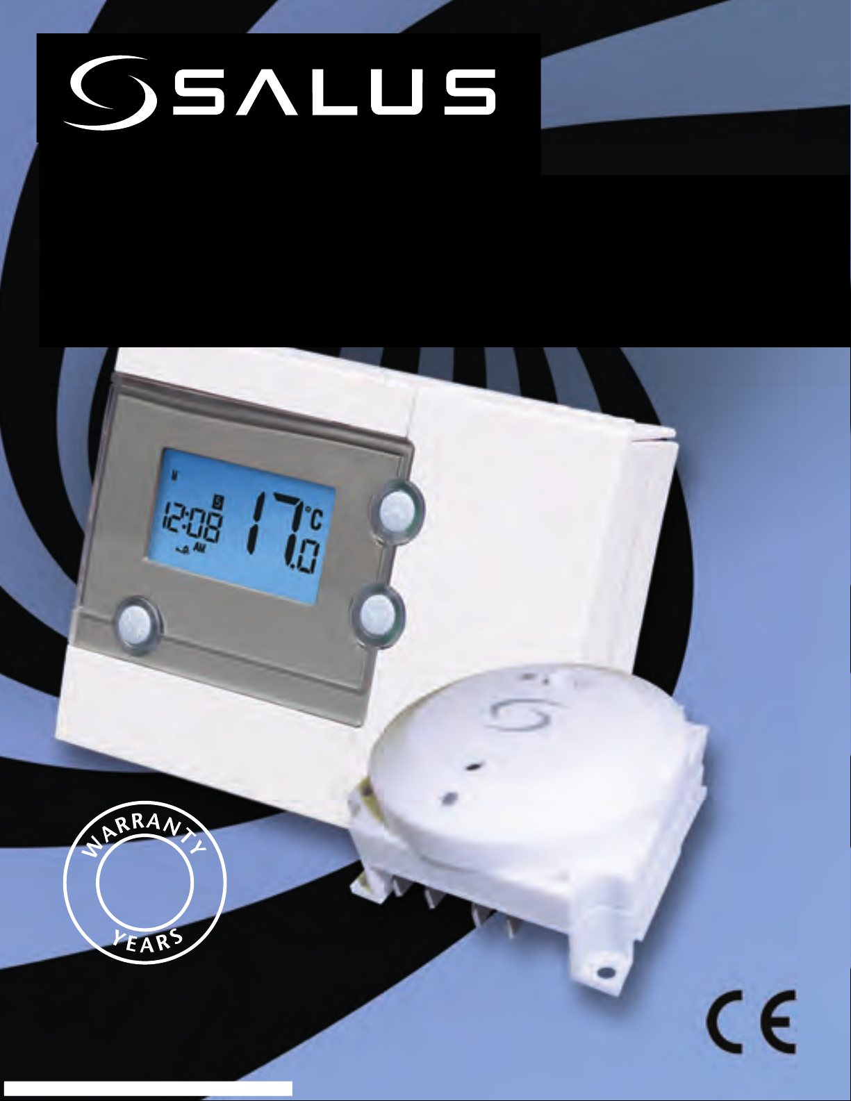
Programmable Digital
Thermostat with RF Boiler Control
2
Instruction Manual
Model No RT500BC
Page 2

PRODUCT COMPLIANCE
This product complies with the essential requirements
of the following EC Directives:
Electro-Magnetic Compatibility Directive 2004/108/EC
•
Low Voltage Directive 2006/95/EEC
•
EC Marking Directive 93/68/EEC
•
R&TTE Directive 99/5/EC
•
SAFETY INFORMATION
These instructions are applicable to the Salus Controls model stated on the
front cover of this manual only, and must not be used with any other make
or model.
These instructions are intended to apply in the United Kingdom only, and
should be followed along with any other statutory obligations.
This accessory must be fitted by a competent person, and installation must
comply with the guidance provided in the current editions of BS7671 (IEE
Wiring Regulations) and Part ‘P’ of the Building Regulations. Failure to
comply with the requirements of these publications could lead to
prosecution.
Always isolate the AC Mains supply before opening or removing the
unit from the wall or wall box.
When fitting batteries don’t mix old and new batteries together. Do
not use rechargable batteries.
Please leave these instructions with the end user where they should be kept
in a safe place for future reference.
2
RT500BC INSTRUCTION MANUAL
Page 3

INTRODUCTION
A programmable room thermostat is a
device that combines the functions of
both a room thermostat and heating
controller into a single unit. The
programmable thermostat is used to
switch the heating system in your home
on and off as needed. It works by
controlling the temperature according to
a series of programmed settings that take
effect at different times of the day.
The RT500 programmable room thermostat from Salus Controls is a stylish and
accurate 5/2 or 7 day programmable electronic thermostat with a large, easy to
read display. This programmable thermostat has been specifically designed to
be used for both Volt Free and AC heating applications. This programmable
thermostat can replace most common residential thermostats and is designed
to be used with electric, gas or oil heating boilers. Unlike ordinary single unit
design thermostats, this is a new type of thermostat separating the operational
functions into two units.
The RF Boiler Control is used for wiring connections and heat on/off control. The
RT500 provides the user interface and temperature sensing / control. The two
units are linked together by a Radio Frequency (RF) signal.
Features
Volt free switching option
•
5/2 or 7 day programming flexibility
•
Built-in start up programming for quick installation
•
Frost protection
•
Large, easy to read display with blue backlight
•
Burner on symbol
•
Easy to use programming
•
User friendly
•
RT500BC INSTRUCTION MANUAL
3
Page 4

INSTALLATION
Please read the important safety information at the start of this manual
before you begin to install the device.
The RT500 programmable room thermostat is easily installed using the
Industry Standard back plate supplied with the unit – this is used purely for
mounting purposes, as no wiring is needed for the RT500. The back plate
can be mounted directly to the wall surface.
The ideal position to locate the RT500 is about 1.5m above floor level. It
should be mounted in a location where the thermostat is accessible,
reasonably lit and free from extremes of temperature and draughts. Do not
mount the thermostat on an outside wall, above a radiator or in a location
where it may be subjected to direct sunlight.
To ensure trouble free operation of the Radio Frequency (RF) signal, always
ensure that the programmable thermostat is mounted away from any
possible sources of interference (such as radios, TV sets, computers, etc.),
and is not mounted on or in close proximity to large metal objects. Installing
the RT500 in enclosed areas such as cellars and basements is not
recommended.
CONNECTING THE RT500 BOILER CONTROL
NOTE: All electrical installation work should be carried out by a
suitably qualified electrician or other competent person.
If you are not sure how to install the Boiler Control consult either with a
qualified electrician, heating engineer or your boiler / heating system
supplier for advice on how to continue.
4
RT500BC INSTRUCTION MANUAL
Page 5

INSTALLING THE RF BOILER CONTROL
1. Remove the front panel
from the boiler.
2. Pull out the mechanical timer.
3. Do not remove link wire.
4. Connect the electrical plug.
5. Push fit boiler control
into housing.
6. Replace the front panel
ensuring a good seal is made.
7. Power up the boiler and check
the correct operation.
RF Boiler Control
LED indicator for learning / output status
Recessed button for ID learning
°
Max. ambient temperature 55
Transmitter link via radio frequency
Current rating 5A (resistive) @ 230V AC
Connections:
1 - Neutral input
2 - Live input
3 - Common input
4 - Normally open output
C
RT500BC INSTRUCTION MANUAL
5
Page 6

BOILER CONTROL WIRING TERMINALS
Terminal Identifier Description
1 N Neutral
2 L Live feed (230V AC)
3 COM Linked Live feed
4 N.O. Switched Live (Normally Open [N.O.] contact)
TYPICAL WIRING INSTALLATION
Boiler Control Boiler
6
RT500BC INSTRUCTION MANUAL
Page 7

RT500 THERMOSTAT DEFAULT SETTINGS
Changes to the default settings should only be made by the Engineer
carrying out the installation or other qualified person.
The installer should select the “jumper”
positions required if changes need to be
made to the factory default settings. The
“jumpers” are found on the rear of the
RT500.
Jumper Function
Program Jumper for 5-2 (factory default setting) or 7
individual days programming.
Span Movable jumper for selecting temperature span
of ± 0.5°C (factory default setting) or ± 1.0°C
1,2,3,4,5 Removable jumpers for altering the RF address
code when used in conjunction with the
teaching mode of the boiler control.
NOTE:
The Reset button must be pressed after changing jumper positions.
RT500BC INSTRUCTION MANUAL
7
Page 8

CHANGING THE BATTERIES ON THE RT500
1. Open the front flap on the right hand side of the unit ,
this reveals the SET & SELECT buttons
2. On the bottom right hand side pull the small flap down
which will reveal the batteries as shown above.
3. Remove the old batteries
4. Now insert the new batteries, insert bottom battery with
the“+” end first followed by the top battery “ – “first .
Note:
When changing the batteries the RT500 will save your settings for 10
sec, after 10 seconds your settings will be lost
8
RT500BC INSTRUCTION MANUAL
Page 9

RF ID CODE SETTING
Normally, the RT500 can link with the Boiler Control the ID code setting. If
there is another unit being used nearby, e.g. in the next house, your Boiler
Control may be triggered by the other RT500. You can change the RF ID
Code to help prevent this problem.
Each Boiler Control can only respond to RF transmissions from a RT500
with the same RF ID code setting.
To adjust the RF ID code of the RT500,
remove one or more of the jumper
caps located on the back of the unit
(labelled 1 to 5 as shown in this
picture): Then follow the steps below
to resync the RF communication.
RT500BC INSTRUCTION MANUAL
9
Page 10

SYNCHRONISING THE BOILER CONTROL
(a) RT500 programmable room thermostat RF Sync mode
- Press and hold "SELECT" to enter ID transmission;
ID code is set by 5 position jumper switches;
- TX sends ID code for 10 minutes.
- during 10 minutes synchronisation, LCD shows "Sy" on
temperature digits and the timer will count down.
- during 10 minutes synchronisation, pressing any key can interrupt ID
code transmission and LCD will return to normal mode, i.e.
temperature and clock.
(b) Boiler Control RF Sync mode
- Press and hold "SYNC" button on the boiler control for a few seconds to
enter ID learning mode, LED flashes.
- Until ID is captured and memorized into EEPROM (within max 12
minutes), LED stops flashing and stays ON (relay close) or OFF (relay
open) if ID is never captured, LED will keep flashing to alert user to
re-sync, until 12 minutes timeout.
To pair the RT500 to the Boiler Module simply press and hold the sync
button on the Boiler module for 3 seconds, at the same time press and
hold Select on the RT500 for 3 seconds, after 3 seconds at the same time
release both the sync button on the boiler module and the select button on
the RT500.
If the Boiler Control successfully receives a signal from the RT500 during the
pairing operation, the Boiler Control will store the new RF address code into
its internal memory. The LED will flash twice if the code is stored correctly,
or 4 times if this was unsuccessful. The Boiler Control will then exit pairing
mode and the LED will go out.
10
RT500BC INSTRUCTION MANUAL
Page 11

TESTING THE RF TRANSMISSION
It is important to site the RT500 in locations where the RF signal cannot be
interrupted.
The receiving range between the RT500 and the Boiler Control is 70 metres
in open air, however many factors can affect the RF transmission and shorten
the operating distance, e.g. shielding by thick walls, foil backed
plasterboard, metal objects such as filing cabinets, general RF interference,
and so on.
The operating range in most household applications is around 30 metres,
which should be more than adequate in most cases. It is advisable to test
the RF transmission from the intended RT500 location to the Boiler Control
location, particularly if you intend to fix the RT500 to the wall. To check the
RF reception, follow the following steps:
1. Press the UP button on the RT500 programmable room thermostat until
the set point temperature is higher than room temperature by a few
degrees.
2. Wait for a few seconds. The “boiler on” (heat call) indicator
should appear on the bottom left of the display on the RT500.
3. Check the LED (light) on the Boiler control - it should be lit.
4. Press the DOWN button to adjust the set point temperature
to be lower than room temperature.
5. Wait for a few seconds, and the “boiler on” (heat call) indicator should
disappear and the LED (light) on the Boiler Control should switch off.
6. Repeat steps 1 to 5 to make sure the LED (light) on the Boiler Control can
turn on and turn off each time.
If you are unable to get a stable RF connection between the Boiler Control
and RT500, check that the Boiler Control has a mains supply. If this isn’t the
problem you can also alter the RF address code by following the ‘RF ID Code
Setting’ section of this manual, and then repeat steps 1 to 5.
RT500BC INSTRUCTION MANUAL
11
Page 12

BOILER CONTROL MANUAL OVERRIDE
The AUTO/MANUAL switch allows you to turn on the
Boiler Control manually if required.
MANUAL AUTO
When the switch on the Boiler Control is in the AUTO (normal) position, the
Boiler Control will automatically receive the RF signal from the RT500 and
control the boiler based on the programming of the RT500.
The user can also move the switch to the MANUAL position; when in this
mode, the boiler will be always turned on and the LED indicator will also be
lit constantly. The manual mode is only to be used as a temporary control if
problems develop with the communication from the RT500.
12
RT500BC INSTRUCTION MANUAL
Page 13

AFTER INSTALLATION
The following table shows the settings of the RT500 programmable
thermostat after Power on, or after RESET is pressed:
Function Status After Reset or Power On
Operation Mode Normal mode
Room Temperature 22.0 °C, updated within 5 seconds
°C indicator On
Clock 12:00
AM/PM indicator AM
Day of Week indicator M
Program Default factory setting
Set Point Temperature Default factory setting
Program Number indicator 5
SET indicator Off
PROG indicator Off
Frost Protection indicator Off
Heat indicator Off
Low-Battery Warning indicator Off, updated within 5 seconds
Output Relay Off
After Power on, the thermostat will operate in Normal mode (Normal mode is
when the thermostat is displaying the room temperature):
The set point temperature is reset to the default setting
•
The room temperature display is updated within 5 seconds
•
The control process starts
•
The programme number is updated to indicate the running program
•
If the Reset Button is pressed, the RT500 will behave in the same way as described
above, user settings stored in the internal memory will be deleted and
overwritten with the default settings, and all programmable thermostat control
settings will be returned to default values.
RT500BC INSTRUCTION MANUAL
13
Page 14
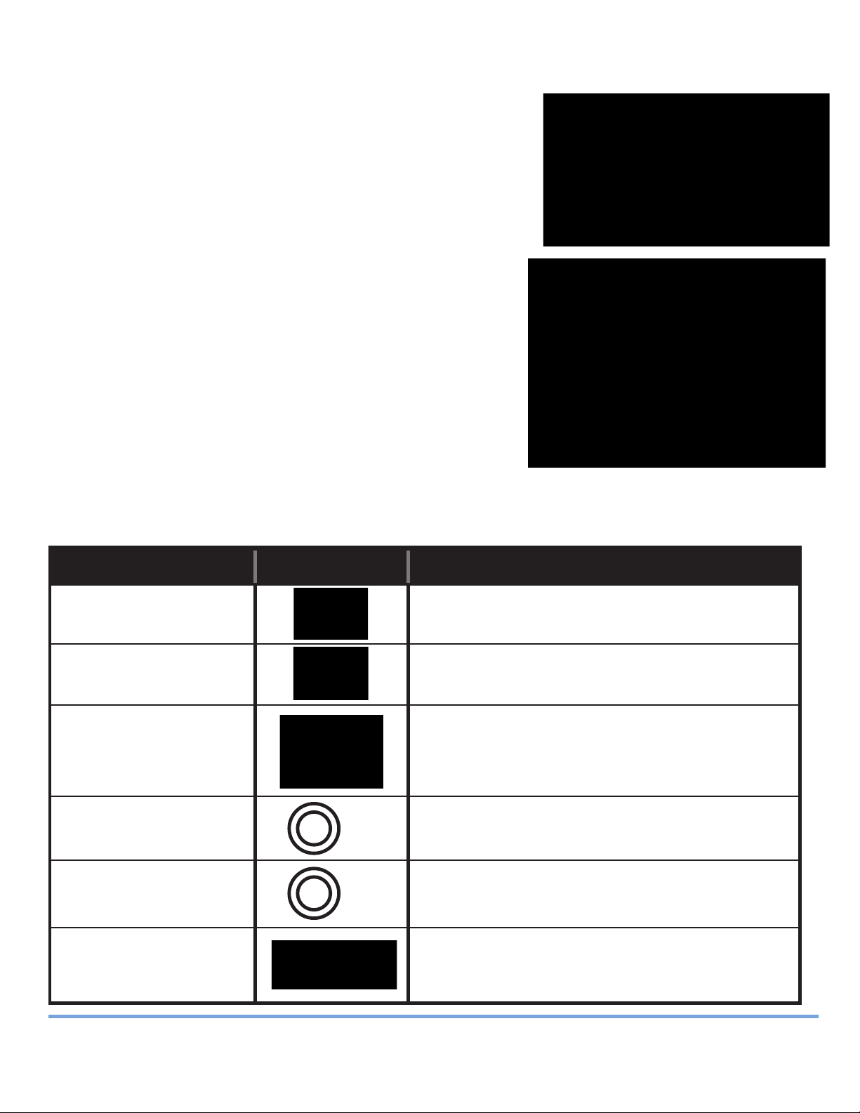
USER INTERFACE
The status and operation of the RT500 is clearly
shown on the display.
This display allows the user to see at a glance the
current status of the heating system, the current
time and day of the week, as well as a clear
indication of the current room temperature.
There are few user controls for the RT500,
making the programmable thermostat very easy
to operate. These controls are shown below,
along with a description of each of their
functions.
USER CONTROL FUNCTION
SUMMARY
Key / Operation Symbol Functions
UP key Increases the selected setting
DOWN key Decreases the selected setting
BACKLIGHT / Manually turns on the LCD backlight
FROST key for 5 seconds, or activates /
deactivates Frost Protection
SELECT key Selects a clock or programme setting
SELECT
SET key Sets a clock or programme setting
and enters learning mode
SET
RESET button Resets the programmable thermostat
to default (original factory) settings
14
RT500BC INSTRUCTION MANUAL
Page 15

OPERATION
The RT500 is configured and adjusted by
the use of a minimal number of user
controls.
SETTING THE TIME
Press and hold SET and SELECT when the
RT500 is in Normal mode for a few seconds
to enter the Clock setting mode. Release
both keys and the display will look like the
image below:
The Time and Day are displayed along with a SET indicator, with all other
indicators cleared from the display. The hour part of the time is flashing to
indicate that it is the currently selected item and is ready to be adjusted.
Press the UP or DOWN keys to increase or decrease the ‘hour’ setting – the
•
selected item will stop flashing while a key is pressed, and will resume
flashing when you release the key.
Press the SELECT key to select the ‘minutes’ section of the time. Set the
•
minutes in the same way as the hour by using the UP and DOWN keys.
Press SELECT again to select the Day, and again change the setting with
•
the UP and DOWN keys.
Press the SET key to confirm the new time and day settings. This will store
•
the changes and return the RT500 to Normal mode.
The RT500 will also return to Normal mode (and save the clock settings) if
no keys are pressed for more than 15 seconds.
RT500BC INSTRUCTION MANUAL
15
Page 16

PROGRAMMING THE RT500
The RT500 offers great versatility with its programming options, allowing
the user to programme the unit to operate on a 5/2 or 7 day control cycle.
The programmable thermostat has a default set of Programmes that have
been designed to meet the needs of most users. If these default programmes
are not suitable for your particular situation, reprogramming the RT500 with
your own settings is a very straightforward operation.
Selection of the default programming mode (5/2 or 7 day) is made by
changing the jumper setting on the rear of the RT500 Control Unit, as
previously described within the Installation section of this manual.
5/2 DAY MODE
5/2 day mode is the default programming mode for the RT500. With this
mode selected, five different sets of time and set point temperatures can be
set for Weekdays or Weekends.
To review or change a programme, press the SET key when the RT500 is in
Normal mode. This will change the unit status to Programme Setting mode.
The LCD display will display programme number 1 and SET PROG, with all
other indicators cleared. The weekdays will be flashing to indicate they are
the selected item and are ready to be adjusted:
16
RT500BC INSTRUCTION MANUAL
Page 17
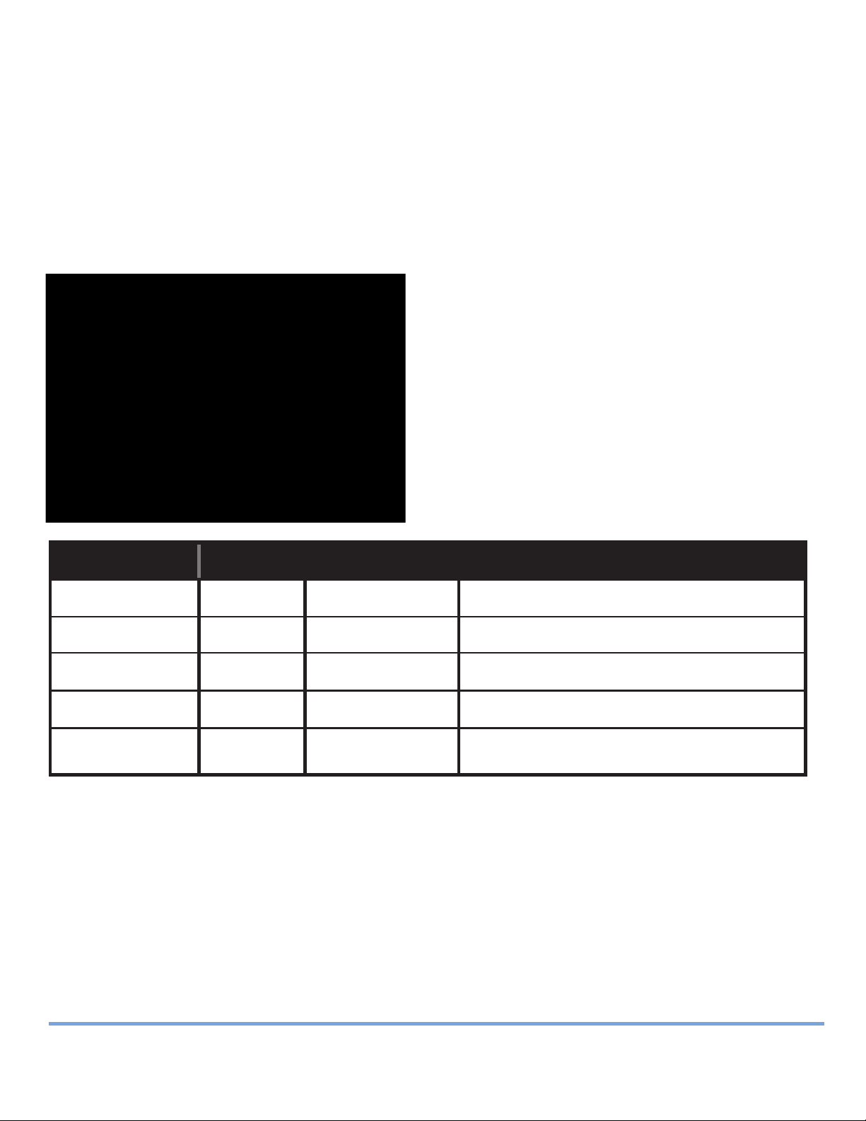
Press the UP or DOWN key to select the programme set for either Weekday or
Weekend to be reviewed or adjusted. Pressing the SET key at any time when
in programming mode will return the RT500 into Normal mode.
Press the SELECT key to confirm the Weekday or Weekend selection. Once
this is set, the ‘Hour’ will flash to indicate that it is the selected item and is
the next item to be adjusted:
Press the UP or DOWN key to adjust the
hour setting to the desired value, and
confirm your selection by pressing the
SELECT key.
Pressing the SELECT key allows you to
step through each of the items to be
reviewed or adjusted within the
programmes in the following sequence:
Programme Function Sequence
1 Hour Minutes Set point temperature
2 Hour Minutes Set point temperature
3 Hour Minutes Set point temperature
4 Hour Minutes Set point temperature
5 Hour Minutes Set point temperature
…before then allowing you to cycle back to Programme 1. Pressing the SET
key at any time will confirm the setting and return to the programme set
selection.
RT500BC INSTRUCTION MANUAL
17
Page 18

7 DAY MODE
The RT500 also offers a 7 day programming mode, which allows you to
programme five different sets of time and set point temperatures for each
day of the week to give a total of 35 separate programme settings.
To review or change a programme, press the SET key when the RT500 is
in Normal mode. This will change the unit status to Programme Setting
mode.
The LCD display will display programme number 1 and SET PROG, with all
other indicators cleared. The weekdays will be flashing to indicate they are
the selected item and are ready to be adjusted.
Press the UP or DOWN key to change the
display to indicate the single day you
want to programme:
Pressing the SET key at any time when in programming mode will return
the RT500 into Normal mode. Press the SELECT key to confirm the Day
selection. Once this is set, the ‘Hour’ will flash to indicate that it is the
selected item and is the next item to be adjusted:
18
RT500BC INSTRUCTION MANUAL
Page 19

Press the UP or DOWN key to adjust the hour setting to the desired value,
and confirm your selection by pressing the SELECT key.
Pressing the SELECT key allows you to step through each of the items to be
reviewed or adjusted within the programmes.
Pressing the SET key at any time will confirm the setting and return to the
programme set selection. Each programme for all the other days of the week
is set in exactly the same way – just repeat the steps shown above, after
entering programming mode and selecting the day you want to programme.
Regardless of which programming mode the RT500 is set for (5/2 or 7 day),
not pressing any keys for 15 seconds will automatically save any
programming changes and exit to Normal mode. You can also review or
change programme settings when Frost Protection is enabled.
RT500BC INSTRUCTION MANUAL
19
Page 20

FROST PROTECTION
To enable the Frost Protection mode, press and hold the BACKLIGHT / FROST
button for a few seconds with the RT500 in Normal mode. Once Frost
Protection is enabled, the set point temperature is automatically set to 5°C
to provide protection from the risk of freezing.
Whenever Frost Protection is activated, the Frost Protection indicator will
flash in the sequence shown below:
While Frost Protection is activated, it will override any programme settings
until the mode is changed. To turn off Frost Protection mode, press and hold
the BACKLIGHT / FROST button for a few seconds.
REVIEWING SET POINT TEMPERATURE
You can view the set point temperature at any time by pressing either the UP
or DOWN key.
When any programme is running, the LCD
display will show the programme set point
temperature with the SET indicator
displayed:
20
RT500BC INSTRUCTION MANUAL
Page 21

When operating in Frost Protection mode,
the LCD display will show a reading of 5 °C
and also display the Frost Protection
indicator:
When operating in Temporary Override
mode, the LCD display will show the
temporary set point temperature:
To exit from the set point review, press any key except the UP or DOWN keys,
or don’t press any keys for a few seconds – either of these actions will return
the RT500 to Normal mode.
TEMPORARY OVERRIDE
It is possible to temporarily override the current set temperature of the
RT500. There are two ways to do this:
While reviewing set point temperature: Pressing the UP or DOWN key
•
will increase or decrease the set point temperature in 0.5 °C steps.
In normal mode press and hold either the up or down key to display the
•
set point temperature. After a few seconds the RT500 will enter temporary
override mode and will allow increase or decrease of the set point
temperature.
RT500BC INSTRUCTION MANUAL
21
Page 22

Once in Temporary Override mode, the
clock and day are displayed, along with the
SET indicator; all other indicators are cleared
from the display. The set point temperature
will flash to indicate that it can be changed:
The set point temperature can be adjusted
within 5 °C to 35 °C.
Temporary Override mode remains active until the new set point settings
are adjusted, Frost Protection is activated or the next programme time /
temperature set point is reached.
On/Off Control
When the RT500 is operating in NORMAL mode, if the Boiler Control has not
received a signal from the RT500 after 1 hour, the Boiler Control will turn off
the boiler, and the LED indicator will flash constantly (two times every
second).
Once the Boiler Control receives a valid ON or OFF signal, the Boiler Control
will control the heating system accordingly.
22
RT500BC INSTRUCTION MANUAL
Page 23

OTHER FUNCTIONS AND CONTROLS
Backlight
The backlight of the RT500 is switched on automatically whenever any of the
keys are pressed. The backlight will remain illuminated for a few seconds
after the last key press.
The backlight will not illuminate if the battery voltage is low.
Battery Status
The RT500 checks the battery voltage frequently during normal
operation. If the battery voltage is sensed as being low, the low battery
indicator will be displayed on the screen.
Although the programmable thermostat will continue to operate normally
at this stage, you should replace the batteries as soon as possible to prevent
any possible operating problems.
Reset Button
The Reset Button is provided as a way to restore the programmable
thermostat to its default factory settings. Pressing this button will delete
any previously entered settings.
Sleep Mode
By pressing both the UP and DOWN keys together for a few seconds, the
RT500 will enter SLEEP mode. In this mode, all of the functions will be
paused to save battery power, with the exception of the clock which will
continue to run in the background.
While in SLEEP mode:
• The LCD display will be blank.
• All output from the RT500 will be turned off immediately.
Press any key to wake up the RT500 and exit SLEEP mode.
RT500BC INSTRUCTION MANUAL
23
Page 24

ENERGY TIP
One way to set and use your room thermostat is to find the lowest
temperature setting that you are comfortable with, and then leave it set at
this temperature. You can do this by setting the room thermostat to a low
temperature, (for example 17 °C) and then increasing the setting by one
degree each day until you are comfortable with the room temperature - you
won’t have to adjust the thermostat further, as adjustment above this setting
will waste energy 1 °C increase in temperature is equal to 3% of your heating
costs.
MAINTENANCE
The RT500 programmable thermostat requires no special maintenance.
Periodically, the outer casing can be wiped clean using a dry cloth (please
DO NOT use solvents, polishes, detergents or abrasive cleaners, as these can
damage the thermostat).
There are no user serviceable parts within the unit; any servicing or repairs
should only be carried out by Salus Controls or their appointed agents.
Should the RT500 programmable thermostat fail to function correctly,
check:
The batteries are the correct type, fitted correctly and are not exhausted
•
- fit new batteries if in doubt.
Heating system is switched on.
•
If the RT500 is still not functioning correctly, press the Reset Button.
•
WARRANTY
Salus Controls warrants that this product will be free from any defect in
materials or workmanship, and shall perform in accordance with its
specification, for a period of two years from the date of installation. Salus
Controls sole liability for breach of this warranty will be (at its option) to
repair or replace the defective product.
24
RT500BC INSTRUCTION MANUAL
Page 25

PRODUCT SPECIFICATION
Model: RT500BC
Type: Electronic programmable thermostat with RF
Boiler Control, designed for Volt Free and AC
heating applications.
Programming
Programming Modes: User selectable for 5/2 or 7 day option.
Number of Programmes: Five (5) user programmes plus factory
default programme.
Override Facility: User selectable programme override facility.
Default Programmes
Programme Output Weekday Weekend
1 ON 6:00 AM 6:00 AM
TEMP 21 ºC 21 ºC
2 ON 8:00 AM 8:00 AM
TEMP 14 ºC 21 ºC
3 ON 4:00 PM 4:00 PM
TEMP 21 ºC 21 ºC
4 ON 6:00 PM 6:00 PM
TEMP 21 ºC 21 ºC
5 ON 10:00 PM 10:00 PM
TEMP 14 ºC 14 ºC
RT500BC INSTRUCTION MANUAL
25
Page 26

Temperature
Scale: Celsius
Display Range: 5 ºC to 35 ºC
Display Resolution: 0.5 ºC
Tolerance: Less than ± 0.5 ºC at 25 ºC
Setpoint Range: 5 ºC to 35 ºC
Measured Air Temperature Range: 5 ºC to 45 ºC
If room temperature is higher than 45
will show HI. If it is lower than 5
º
C, it will show LO.
Clock
Accuracy: ± 1 minute per month
º
C,display
Display Format: 12 hour
Frost Protection
Setting: 5 ºC
RT500
Power Source: 2 x AA alkaline batteries
(do not use rechargeable batteries)
Radio Frequency: 868 MHz
Boiler Control
Power Source: 230V AC / 50Hz
Radio Frequency: 868 MHz
Switching Voltage: 0-230V AC / 50Hz
Switching Current: 5A resistive, 1A inductive
Environment
Operating Temperature: 0 ºC to + 40 ºC
Storage Temperature: - 20 ºC to + 60 ºC
26
RT500BC INSTRUCTION MANUAL
Page 27

RT500BC Warranty
Salus Controls warrants that this product will be free from any defect in
materials or workmanship, and shall perform in accordance with its
specification, for a period of two years from the date of installation. Salus
Controls sole liability for breach of this warranty will be (at its option) to
repair or replace the defective product.
Customer Name: ....................................................
Customer Address: .................................................
...............................................................................
Post Code: ..................... Tel No: ............................
Email: .....................................................................
Engineers Company: ..............................................
Tel No: ...................................................................
Email: .....................................................................
Date of Intallation: .................................................
Engineers Name: ....................................................
Engineers Signature: ..............................................
RT500BC INSTRUCTION MANUAL
27
Page 28
salus-tech.
Sales
Technical
Salus Controls plc, Salus House, Dodworth Business Park South,
Email: [email protected] Tel: 01226 323961
:
Email: [email protected] Tel: 01226 323961
:
Whinby Road, Dodworth, Barnsley S75 3SP
 Loading...