

Page 1

Instruction Manual
Model No’s PH60/PH60-1/PH60-C
PI Control
Programmable Thermostatic
Radiator Valve Control Head
Page 2

PH60 INSTRUCTION MANUAL
2
PRODUCT COMPLIANCE
This product complies with the essential requirements of the
following EC Directives:
•
Electro-Magnetic Compatibility directive 2004/108/EC
•
Low Voltage Directive 2006/95/EEC
•
EC Marking directive 93/68/EEC
SAFETY INFORMATION
These instructions are applicable to the SALUS Controls model
stated on the front cover of this manual only, and must not be
used with any other make or model.
These instructions should be followed along with any other
statutory obligations - if you are in any doubt, please contact
the SALUS Controls technical helpline.
Please leave these instructions with the end user where they
should be kept in a safe place for future reference.
Page 3

INTRODUCTION
A Thermostatic Radiator Valve (TRV) is a self-regulating valve fitted
to hot water heating system radiators. The TRV controls the
temperature of a room by regulating the flow of hot water to the
radiator.
The PH60 from SALUS Controls is a stylish and accurate TRV
programmable control head designed for independent control of
central heating radiators. It is fitted to a new or existing TRV, and
works by controlling the radiator temperature according to a series
of programmed settings.
The PH60 is fitted with an easy to read Liquid Crystal Display (LCD)
and a five key operating panel, which is coupled with a unique,
smart design that makes the PH60 easy to programme and operate.
PI Control
The SALUS PH60 is a PI (Time Proportional & Integral) control product
as defined in the Building Regulations, which makes the heating
system operate up to 15% more efficient and provides close,
accurate control. Please note there is no span on the PH60 PI.
Features
•
PI Control for accuaracy
and efficiency
•
LCD with Backlight
•
Stylish Casing
•
Simple to Install
•
6 Control Modes
•
Temporary Override Function
•
Built in Start-up Programmes
•
Limescale Protection feature
•
7 day Independent Programming
PH60 INSTRUCTION MANUAL
3
PH60-1
PH60
PH60C
Page 4

INSTALLATION
Please read the important safety information at the start
of this manual before you begin to install the device.The
PH60 is easily installed – whether fitted as part of a new
installation, or in place of an existing TRV control head.
Battery Installation and Replacement
After Installation
After completing installation and powering up the PH60 for the first
time the controller will go through an adaptation procedure to check
that the valve has been installed correctly. The PH60 will behave in the
following way:
PH60 INSTRUCTION MANUAL
4
Push button to
gain access to
battery
compartment.
Please insert
batteries
correctly as
indicated.
Installation of the batteries is a straightforward
operation. Remove end cap from the PH60 body as
shown in this picture, and insert the batteries,
please make sure that the batteries are correctly
inserted.
About Valve Compatibility
An adapter for valves from the following manufactuers:
Heimeier, Junkers, Landy + Gyr, Honeywell-braukmann,
Oventrop M30X1.5 is not required.
For Danfoss valves RA-Series, you may require the
following adapter (supplied). Slide the adapter onto
the valve completely and tighten the screw.
The PH60 is attached to the valve body by screwing the
locking collar at the base of the controller onto the
threaded section of the TRV body, as shown in this
picture. The locking collar only needs to be tightened
by hand – do not use a spanner or pipe grips as you
may damage the PH60, TRV or both.
Page 5

PH60 INSTRUCTION MANUAL
5
Display Comments
All the indicators on the display and the backlight
will be turned on for two seconds.
The internal firmware version will then be displayed for
one second (the numbers displayed may be different to
the one shown here, depending on the firmware
revision of the individual PH60 controller)
The PH60 will then enter ADAPTATION mode. If there
are no problems with the battery or gear assembly, the
display will be as shown in this example. The flashing
indicator shows the motor is operating and retracting
the control pin.
Once the control pin is fully retracted, the display stops
flashing and the display will indicate the valve is open.
Install the TRV to the valve. To move to the next stage,
press any key.
The flashing indicator shows the motor is operating and
extending the control pin to close the valve.
Once closed, the display will change as shown in this
example. The flashing indicator shows the motor is
operating and retracting the control pin again. If this
final stage is completed successfully, the PH60 will enter
NORMAL mode
When entering NORMAL mode for the first time or after
a RESET), the time and day are set to 00:00 and 1. They
are flashing to prompt you to set them to the correct
values – to do this, please follow the ‘Time Setting
Mode’ procedure on page 18.
Page 6

At the start of the adaptation procedure, the controller will
check the battery and gear assembly; if there are any problems,
the following screens will be displayed:
Display Error
This example shows the battery voltage is low.
This example shows the gear assembly is not installed.
If there is a problem during the adaptation procedure, the
controller will stop and restart the process. If the problem still
exists, an error code will be displayed;
Error Code Description
Er1 Stroke too short. During the ‘P2’ adaptation stage the pin
stopped extending before reaching its minimum controllable point.
Er2 Stroke too long. During the ‘P2’ adaptation stage the pin did not stop
extending after reaching its maximum controllable point.
Er3 Unequal stroke. The measured strokes during stages
‘P2’ and ‘P3’ are not equal (this is normally caused
by weak batteries).
Er4 Operation over time. The motor has been operating
for over 100 seconds before reaching the end point.
PH60 INSTRUCTION MANUAL
6
Page 7

PH60 INSTRUCTION MANUAL
7
An example of an error message is shown below:
Display Error Description
Error 2 (Er2 – stroke too long) occurred
during the adaptation process.
Pressing any key will restart
the adaptation process.
It is also possible to enter ADAPTATION mode manually if the PH60 is
in NORMAL mode. This is done by pressing the SET key until ‘AdAP’ is
shown on the display. Releasing the SET key will start the adaptation
process. If an error is displayed during the manually selected
adaptation, pressing any key or waiting 8 seconds without a key press
will return the PH60 to NORMAL mode.
Page 8

USER INTERFACE AND CONTROLS
The status and operation of the
PH60 can be clearly seen on the
backlit Liquid Crystal Display
(LCD) - this display allows the
user to see at a glance the current
status of the valve controller.
The display consists of a combination of symbols and
alphanumeric displays. The status indicator symbols and their
meanings are shown in the following table:
User Control Function Summary
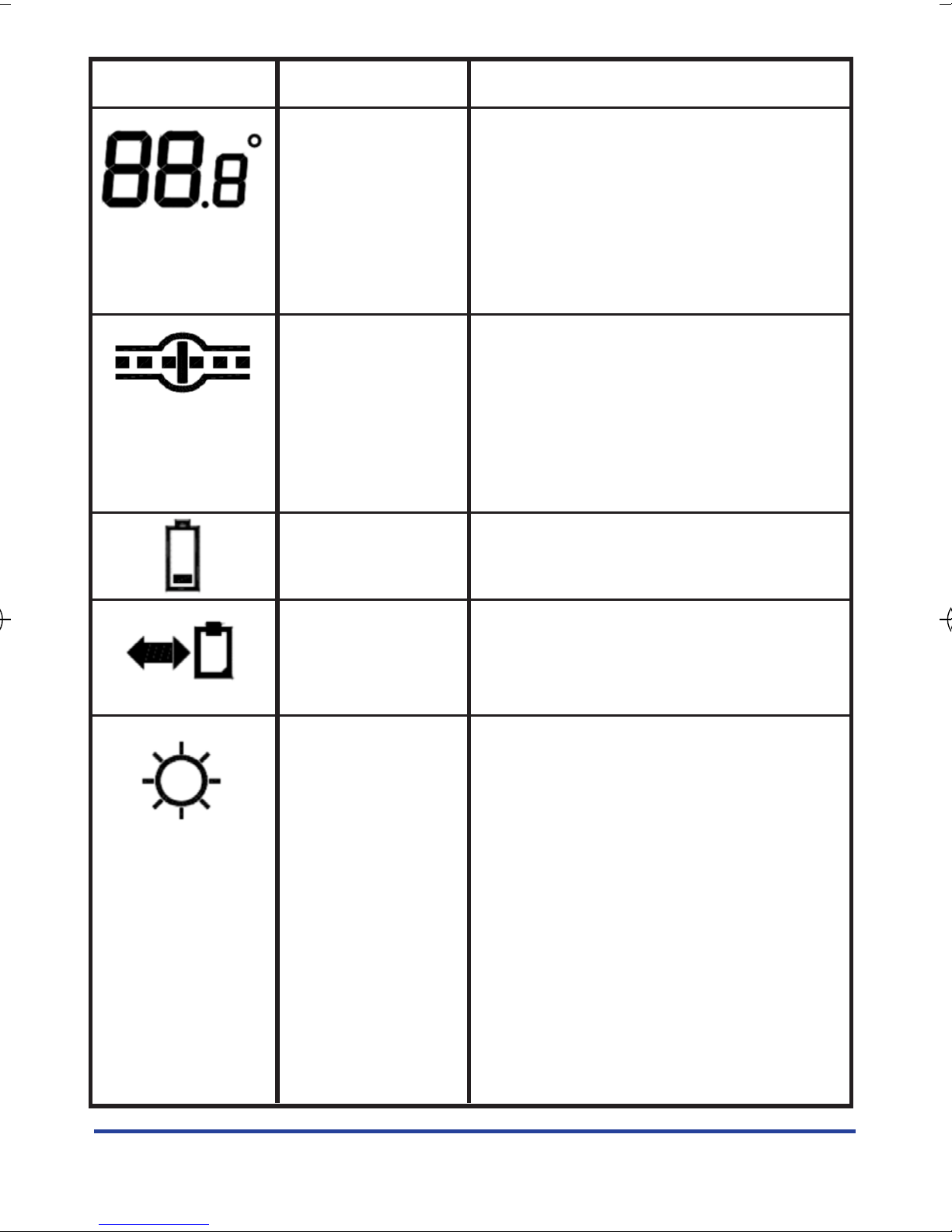
Indicator Description Function
1 2 3 4 5 6 7 Day of Week In NORMAL mode indicates
Indicator the current day of the week.
In PROGRAMME mode indicates
the day being programmed.
In PROGRAMME COPY mode
indicates the source and
destination day.
Time Indicator In NORMAL mode indicates the
current time. In PROGRAMME
mode indicates the
programme time.
PH60 INSTRUCTION MANUAL
8
Page 9
PH60 INSTRUCTION MANUAL
9
Indicator Description Function
Temperature In NORMAL mode indicates the
Indicator room temperature. In
PROGRAMME mode indicates
the set temperature. In
TEMPERATURE mode indicates
the set temperature.
Valve Status A ‘water flow’ animation is
Indicator shown when the valve is opened.
A ‘closed valve’ animation is
shown when the valve is closed.
Indicator flashes when the
valve is opening.
Low Battery Indicator flashes when the
Indicator battery voltage is low.
Programme In PROGRAMME COPY mode
Copy Indicator shows the source and
destination day.
Comfort In AUTO mode indicates the set
Temperature temperature is ‘Comfort’.
Mode Indicator In MANUAL mode indicates the
set temperature is ‘Comfort’.
In PROGRAMME SETTING
mode indicates the set
temperature selected for the
hour is ‘Comfort’.
Page 10

PH60 INSTRUCTION MANUAL
10
Indicator Description Function
Econ In AUTO mode indicates the set
Temperature temperature is ‘Econ’.
Mode Indicator In MANUAL mode indicates the
set temperature is ‘Econ’.
In PROGRAMME SETTING mode
indicates the set temperature
selected for the hour is ‘Econ’.
Party In NORMAL mode indicates
Temperature the set temperature is ‘Party’.
Mode In MANUAL mode indicates the
Indicator set temperature is ‘Party’.
Holiday In NORMAL mode indicates
Temperature the set temperature is ‘Holiday’.
Mode In MANUAL mode indicates the
Indicator set temperature is ‘Holiday’.
Frost Protection In NORMAL mode indicates the
Temperature set temperature is ‘Frost
Mode Indicator Protection’. In MANUAL mode
indicates the set temperature
is ‘Frost Protection’.
Page 11
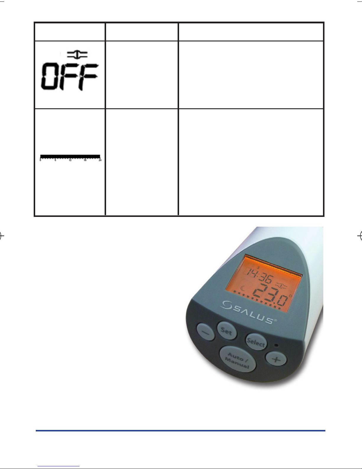
Indicator Description Function
‘OFF’ Mode Indicates the PH60 is operating
Indicator in ‘OFF’ mode - a special manual
control mode that closes the
TRV regardless of the room
temperature or set temperature.
Programme In NORMAL mode indicates the
Profile Indicator controller is running in AUTO
(Programme) control mode.
In PROGRAMME mode indicates
the profile of the selected day.
In the PROGRAMME COPY mode
it indicates the program profile
of the source day.
There are few user controls for
the PH60, making the controller
very easy to operate. These
controls are shown below,
along with a description of each
of their functions.
PH60 INSTRUCTION MANUAL
11
Page 12

User control function summary:
Key / Operation Functions
+ Increases or changes the selected setting.
- Decreases or changes the selected setting.
SET Enters Menu or confirms a menu selection
SELECT Selects item when in SET mode
AUTO/MANUAL In NORMAL mode, press to choose the AUTO
programme, or any of the MANUAL control modes.
Reset Button Press and hold for more than one second to reset the
controller to default (original factory) settings.
OPERATION
The PH60 is configured and
adjusted by the use of five
touch sensitive buttons.
PH60 INSTRUCTION MANUAL
12
Page 13

PH60 INSTRUCTION MANUAL
13
Normal Mode
NORMAL mode is the default operating mode of the PH60.
This is a typical NORMAL operating mode display.
• The time is midnight, and the day is 1 (Monday)
• The room temperature is 23 ºC
• The valve animation shows that the TRV is open
• The profile indicator at the bottom of the display
shows the PH60 is in AUTO mode
• The ‘Econ’ indicator shows the PH60 set
temperature mode is ‘Econ’
Auto and Manual Control Modes
When the PH60 is operating in AUTO mode, TRV control is
based on the programme currently set. In MANUAL mode, the
set temperature is fixed depending on which set temperature
mode (Off, Comfort, Econ, Party, Holiday or Frost) has been
selected. The temperature mode indicator and programme
profile indicator show what mode the PH60 is operating in:
Page 14

Display Operation
In this example, the PH60 is set to operate
in ‘Comfort’ mode.
The temperature mode indicator will flash if
temporary override mode has been selected.
In this example, the PH60 is set
to operate in ‘Econ’ mode.
When operating in MANUAL mode, programmes are not used
– the profile indicator is not displayed, and the set temperature
is fixed to the temperature selected by the user.
The images below show the PH60 operation in MANUAL mode
with the set temperature in ‘Comfort’, ‘Econ’, ‘Party’, ‘Holiday’
and ‘Frost’ modes:
Changing Control Mode
Pressing the AUTO/MANUAL key when the PH60 is in
NORMAL mode will allow you to change between automatic
control and the six manual control modes. Pressing the + or –
keys allow you to change the set temperature:
PH60 INSTRUCTION MANUAL
14
Page 15

Display Operation
Press the AUTO/MANUAL key once and the
PH60 will display ‘SEt’ and the current
control mode.
Press and hold the SET key or wait for 8
seconds to return to NORMAL mode
without making any changes.
Press the AUTO/MANUAL key again (or the
SELECT key) to change the control mode.
Use the AUTO/MANUAL key to scroll
through the control modes (Auto
Manual Comfort Manual Econ
Manual Party Manual Holiday
Manual Frost Manual Off Auto).
Press the SET key or wait for 8 seconds to
return to NORMAL mode and the PH60
will start to operate in the new mode.
When choosing the control mode, you can
use the + or – keys to change the
set temperature setting.
You cannot adjust the set temperature
if ‘Off’ mode has been selected.
Pressing the + or – key in NORMAL mode will
allow you to review the current set
temperature. ‘SEt’ and the set temperature
will be displayed until the key is released.
If the + or – key is held for more than
two seconds, the display will flash once
and change to setting mode.
PH60 INSTRUCTION MANUAL
15
Page 16

Accessing the Menus
To access the Mode screens, press the SET key as indicated in
the table below:
Display Operation
Press and hold the SET key for one second
to enter the time setting mode. The display
will change to show ‘CLOC’.
Press and hold the SET key for four seconds
to enter the programme setting mode.
The display will change to show ‘Pro’.
Press and hold the SET key for 7 seconds
to enter the programme copy mode.
The display will change to show ‘Pro’
and the copy icon.
Press and hold the SET key for 10 seconds
to enter the option setting mode. The
display will change to show ‘OPn’.
Press and hold the SET key for 13 seconds
to enter the adaptation mode. The display
will change to show ‘AdAP’.
Press and hold the SET key for 16 seconds to return
the PH60 to NORMAL mode.
PH60 INSTRUCTION MANUAL
16
Page 17

PH60 INSTRUCTION MANUAL
17
Time Setting Mode
The Time Setting mode allows the setting of the day and time
– these are the only items displayed on the screen.
• Initially, the hour will be flashing;
press the + or – keys to change
the setting.
• Press the SELECT key to select
the minutes; press the + or – keys
to change the setting.
• Press the SELECT key to select the
day; press the + or – keys to
change the setting.
Pressing the SET key, or not pressing any keys for 30 seconds
will return the PH60 to NORMAL mode.
Programme Setting Mode
The PH60 offers great versatility with its programming options,
allowing the user to programme the controller to operate on a
7 day individual, 5/2 or 7 day control cycle. The controller has
a default set of Programmes that have been designed to meet
the needs of most users:
Page 18

Day of Week Factory Preset Programme
Monday
Tuesday
Wednesday
Thursday
Friday
Saturday
Sunday
In the examples shown above, the time between 0600 to 2200 will
represent a ‘Comfort’ setting ( High set point temperature) The blank
areas will represent an Econ setting ( Low set point temperature)
Please note, Econ temperature cannot be set higher than Comfort
temperature setting.
PH60 INSTRUCTION MANUAL
18
The table below reflects a 24hr day.
Page 19

PH60 INSTRUCTION MANUAL
19
All the set temperatures are adjustable in 0.5 ºC steps.
‘Comfort’ and ‘Econ’ are used in programmes.
If these default programmes are not suitable for your particular
situation, reprogramming the PH60 with your own settings is
a very straightforward operation.
After entering the Programme Setting mode, the programme
settings are adjusted as follows:
The PH60 has 5 preset set temperature modes:
No Programme Description
1 Comfort A warm, comfortable setting.
Adjustable between 7 – 30 ºC
2 Econ A lower setting than ‘Comfort’ to save energy.
Adjustable between 7 – 30 ºC
3 Party An alternative comfortable setting, similar to
‘Comfort’. Adjustable between 15 – 30 ºC
4 Holiday A low setting used when the house is not occupied
for a long period. Adjustable between 7 – 15 ºC
5 Frost An even lower setting than ‘Holiday’, just high
enough to stop pipes freezing.
Adjustable between 4 – 7 ºC
Page 20

Display Operation
Initially, day 1 (Monday) will be displayed. The
clock hour will be flashing, along with a flashing
cursor on the profile indicator at the bottom of
the display.
Press SELECT to change the programme time. In
this example, the time has changed to 11:00, and
the set temperature is using the ‘Comfort’
programme, set at 21 ºC
To change the set temperature, press the + key to
change the temperature mode to ‘Comfort’, or
the – key to change to ‘Econ’. The set time will
then advance by 1 hour.
Press the SET key to advance to the next day. The sequence
is 1 – 2 – 3 – 4 – 5 – 6 – 7 – (1 – 5) – (6 – 7) – (1 – 7). Press
SET again to return to NORMAL mode. (1 – 5), (6 – 7) and
(1 – 7) are called day groups – all the days included are
programmed together. The programming method is the
same as single day programming.
If the programme settings of the involved days are
different, the temperature indicator, set temperature, and
programme profile are not displayed. If the + or – keys are
pressed to change the programme all the days of the
displayed day group will be reset to the default programme
setting. The temperature indicator, set temperature and
programme profile will then be displayed to allow you to
continue adjusting the programme settings.
If no keys are pressed for 30 seconds, the PH60 will automatically
return to NORMAL mode.
PH60 INSTRUCTION MANUAL
20
Page 21

PH60 INSTRUCTION MANUAL
21
Programme Copy Mode
The PH60 programme copy mode allows the user to copy one
day’s programme settings to another day.
If no keys are pressed for 30 seconds, the copy will be cancelled
andthe PH60 will automatically return to NORMAL mode.
Display Operation
On entering programme copy mode, day 1 (Monday) is
displayed and flashing. The programme copy indicator
is also displayed with an animated pointer pointing
towards the clipboard.
Press the + or – keys to select and copy other days,
then press the SET key to go to the next screen.
Initially, the same day that was chosen as the source is
also set as the destination. Press the + or – keys to select
other days as the destination. Press the SET key to
complete the copy operation and return to
NORMAL mode.
Groups of days can be selected as the destination, so
that several days can be programmed together. This
example shows that all the weekdays have been set as
the copy destination.
Page 22

PH60 INSTRUCTION MANUAL
22
Option Setting Mode
There are 5 user option modes available: Language, Stroke
Position, Open Window Detection Sensitivity, Temperature
Offset and Limescale Protection:
Display Operation
The first option is Language. "LAnG" for English.
"SPrA" for German. The current language setting
is displayed.
The default language setting for the PH60 is English
(‘EnG’). Pressing the + or – keys will allow you to
change the setting. Pressing the SET key will confirm
the choice and move to the next screen.
This is adjusted and set automatically in adaptive
mode, see AdAP page 5. There is no change required.
The third option is the Open Window Detection
Sensitivity. ‘OPEn’ and the current sensitivity time
setting is displayed.
Pressing the + or – keys will allow you to change the
setting to the options of 0, 1, 2 or 3. (0 turns off the
option, 1 – 3 indicates low to high sensitivity).
Pressing the SET key will confirm the choice and move
to the next screen.
Page 23

Display Operation
The fourth option is the Temperature Offset. ‘OFS’ and
the current offset temperature setting is displayed.
Pressing the + or – keys will allow you to change
the setting between – 3.5 to + 3.5 ºC in 0.5 ºC
steps. Pressing the SET key will confirm the choice
and move to the next screen.
The fifth option is the Limescale Protection. ‘LInE’ and
the current setting is displayed.
Pressing the + or – keys will allow you to change
the setting to the options of ‘YES’ or ‘NO’. Pressing the
SET key will confirm the choice and return the
PH60 to NORMAL mode.
PH60 INSTRUCTION MANUAL
23
If no keys are pressed for 30 seconds, the PH60 will
automatically return to NORMAL mode.
Page 24

PH60 INSTRUCTION MANUAL
24
Adaptation Mode
It is possible to enter ADAPTATION
mode manually if the PH60 is in
NORMAL mode. This is done by
pressing the SET key until ‘AdAP’ is
shown on the display.
Releasing the SET key will start the adaptation process. If an
error is displayed during the manually selected adaptation,
pressing any key or waiting 8 seconds without a key press will
return the PH60 to NORMAL mode.
Page 25

PH60 INSTRUCTION MANUAL
25
OTHER FUNCTIONS AND CONTROLS
Valve Status Indication
The status of the TRV is displayed on the PH60 is shown by the
valve status indicator:
Display Status
When the TRV is closed, the PH60 will display
a ‘closed valve’ indicator.
When the TRV is open, the PH60 will display
a ‘water flow’ animation.
When the TRV is operating, the PH60 will display
a flashing valve indicator.
Page 26

PH60 INSTRUCTION MANUAL
26
Backlight
The backlight of the PH60 is switched on automatically
whenever any of the keys are pressed. The backlight will
remain illuminated for 10 seconds after the last key press. The
backlight does not operate if the PH60 is in ADAPTATION
mode, or if the battery is low.
Limescale Protection
If the TRV is not operated for long periods, limescale deposits
can build up in the valve and prevent correct operation. The
PH60 has an inbuilt limescale protection mode to prevent this
problem.
When limescale protection mode is enabled, the PH60 will
operate the TRV at least once a day.
At 13:00 every day, if the valve has not been operated in the
last 24 hours the PH60 will open and close the valve once. This
will be indicated on the display as shown:
When enabled, limescale protection will continue to
operate even if the ‘Off’ programme has been selected.
Page 27

Open Window Detection
If a door or window is opened, this may cause a sudden drop
in the room temperature and cause the TRV to be opened by
the controller. This drop in room temperature is usually
temporary, and in this situation it is usually better to turn off
the heating.
When Open Window detection is enabled, the PH60 will
automatically monitor the room temperature. If the
temperature falls quickly (within a user selectable setting of
1.0, 1.5 or 2.5 ºC) the PH60 will enter Open Window mode and
close the TRV. If the room temperature stops falling (or starts
to rise) the Open Window mode will stop and reset the
detection state.
When Open Window mode is operating, it will be indicated on
the display as shown below:
The Open Window state is automatically cancelled after 15
minutes, or if any key is pressed.
PH60 INSTRUCTION MANUAL
27
Page 28

PH60 INSTRUCTION MANUAL
28
Reset Button
The Reset Button is provided as a way to restore the PH60 to its
default factory settings. Pressing this button will delete any
previously entered settings.
The default factory settings for the PH60 are:
Function Default Setting
Operating Mode Adaptation mode
Clock 00:00, 1
Programme Reset to default
Control Mode Auto
Room Temperature Depends on current room temperature
Room Temperature Offset 0.0 ºC
Set Temperature Depends on current programme
‘Comfort’ Set Temperature 21 ºC
‘Econ’ Set Temperature 16 ºC
‘Party’ Set Temperature 21 ºC
‘Holiday’ Set Temperature 10 ºC
‘Frost’ Set Temperature 5 ºC
Backlight Off
Keylock Disabled
Span 0.5 ºC
Window Open Detection Sensitivity 2 (medium)
Temperature Offset 0.0 ºC
Limescale Protection Enabled
Battery Low Warning Based on current battery condition
Valve Status Open (after completion of adaptation)
Page 29

Keylock
The PH60 keypad can be locked to prevent any accidental
changing of the controller settings.
The keylock mode can be turned on when the PH60 is in
NORMAL mode by pressing and holding the SELECT key for
three seconds. Once active, pressing any key will show ‘LOC’ on
the display, as shown below:
If you are unable to change any of the
controller settings, check that the
keylock mode is not turned on. To
disable the keylock, press and holding
the SELECT key again for three seconds.
Temporary Override Mode
When the PH60 is in AUTO mode, the user can temporarily
override the current set temperature. This override will remain
active until the next programmed set temperature becomes
active.
When Temporary Override mode is set,
the TEMPERATURE mode indicator
(‘Comfort’ or ‘Econ’) will flash. To end
the temporary override, press the
AUTO/MANUAL key and reselect the
AUTO mode.
PH60 INSTRUCTION MANUAL
29
Page 30

PH60 INSTRUCTION MANUAL
30
Low Battery Detection
The PH60 constantly monitors battery voltage. When battery
voltage falls below a preset point, the low battery indicator will
be shown on the display as shown below:
The low battery indicator will continue
to be displayed until the battery
voltage returns to normal levels. The
display backlight will not operate
when the battery level is low. When
the low battery indicator is displayed,
you should replace the batteries as
soon as possible.
The PH60 will also monitor the maximum motor speed
achieved when the valve is being operated. If the motor speed
is too low, the PH60 will assume that the battery is low or there
is some problem with the valve actuator.
In this situation, the PH60 will stop
normal operation and enter battery
protection mode, as shown in the
image. The PH60 will set the TRV to a
half open position – the valve will stay
in this condition until the PH60 is reset
by the user.
Page 31

Off Mode
The PH60 has a special manual control mode (‘Off’ mode) that
will close the TRV regardless of the room temperature or set
temperature.
Off mode is generally used when heating is not needed, for
example in the summer. When Off mode is operating, it will
be indicated on the display as shown below:
If limescale protection is enabled, it will still be active in Off
mode. Open Window mode is disabled if the PH60 is operating
in Off mode.
PH60 INSTRUCTION MANUAL
31
Page 32

PH60 INSTRUCTION MANUAL
32
ENERGY TIP
One way to set and use your heating system is to find the
lowest temperature setting that you are comfortable with in
each room, and then leave it set at this temperature. You can
do this by setting the PH60 to a low temperature, (for example
17 °C) and then increasing the setting by one degree each day
until you are comfortable with the room temperature - you
won’t have to adjust the thermostat further, as adjustment
above this setting will waste energy - a 1 °C increase in
temperature is equal to 3% of your heating costs.
MAINTENANCE
The PH60 programmable TRV controller requires no special
maintenance. Periodically, the outer casing can be wiped clean
using a dry cloth (please DO NOT use solvents, polishes,
detergents or abrasive cleaners, as these can damage the
controller).
There are no user serviceable parts within the unit; any
servicing or repairs should only be carried out by Salus Controls
or their appointed agents.
Should the PH60 TRV controller fail to
function correctly, check:
• The batteries are the correct type, fitted correctly
and are not exhausted - fit new batteries if in doubt.
• Heating system is switched on.
• If the PH60 is still not functioning correctly,
press the Reset Button.
Page 33

PRODUCT SPECIFICATION
Model: PH60
Type: Electronic programmable
thermostat for radiator
valve control.
Clock
Display Modes: 24 hour clock with Day
of Week display.
Tolerance: ±60 seconds per month
Programming
Programming Modes: User selectable for 7 day individual,
5/2 or 7 day options
Hourly programming to ‘Comfort’
or ‘Econ’ set points
Group programming function
Override Facility: User selectable programme
override facility.
Temperature
Scale: Celsius
Tolerance: Less than ± 0.5 ºC at 25 ºC
Display Range: 0.0 ºC to 40.0 ºC
Display Resolution: 0.5 ºC
PH60 INSTRUCTION MANUAL
33
Page 34

Control Modes
Operating Modes: Auto (program) or Manual
(in manual mode, user can select
one of 6 preset temperature modes)
Programme Range Step
Off N/A N/A
Comfort 7 – 30 ºC 0.5 ºC
Econ 7 – 30 ºC 0.5 ºC
Party 15 – 30 ºC 0.5 ºC
Holiday 7 – 15 ºC 0.5 ºC
Frost 4 – 7 ºC 0.5 ºC
Power Supply
Power Source: 2 x AA (LR6) alkaline batteries
Battery Life: Approximately 1 year
Memory and Operating Backup
Memory Backup: Electrically Erasable Programmable
Read Only Memory (EEPROM)
Environment
Operating Temperature: 0 ºC to + 50 ºC
Storage Temperature: - 20 ºC to + 60 ºC
PH60 INSTRUCTION MANUAL
34
Page 35

Salus Controls warrants that this product will be free from any defect
in materials or workmanship, and shall perform in accordance with its
specification, for a period of two years from the date of purchase. Salus
Controls sole liability for breach of this warranty will be (at its option)
to repair or replace the defective product.
PH60 Warranty
Customer Name: ....................................................................
Customer Address: .................................................................
...............................................................................................
Post Code: ..................... Tel No: ............................................
Email: .....................................................................................
Engineers Company: ..............................................................
Tel No: ...................................................................................
Email: .....................................................................................
Intallation Date: .....................................................................
Engineers Name: ....................................................................
Engineers Signature: ..............................................................
Page 36

Email: sales@salus-tech.com Tel: 01226 323961
Email: tech@salus-tech.com Tel: 01226 323961
Sales
:
Technical
:
SALUS Controls plc, Salus House, Dodworth Business Park South,
Whinby Road, Dodworth, Barnsley S75 3SP
salus-tech.
15/05/2013 Ver013
 Loading...