

Saivod Sap 685 Instruction Manual
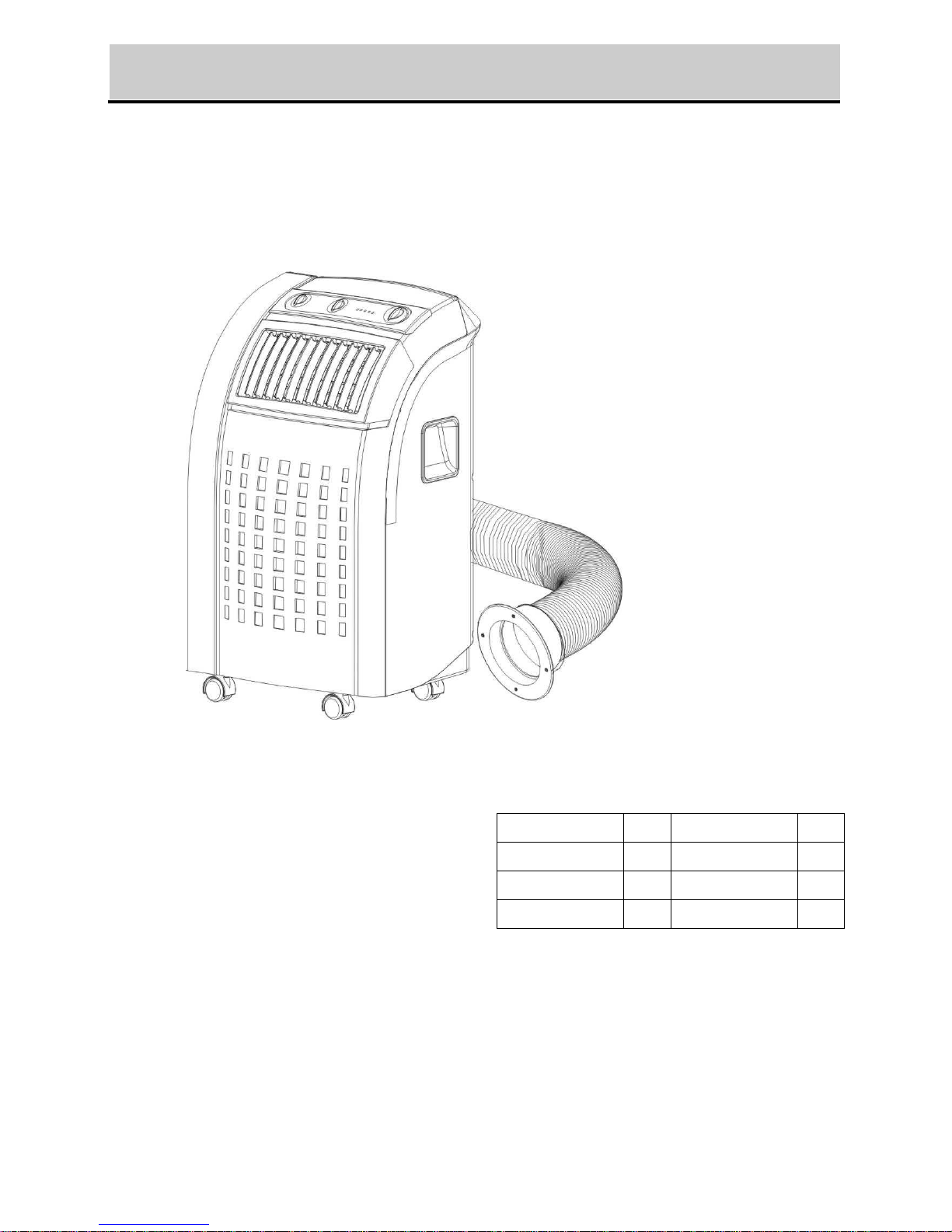
PORTABLE AIR CONDITIONER
Instruction Manual
TC-N028M
TC-T028M
TC-N028MH
TC-T028MH
TC-N028R
TC-T028R
TC-N028RH
TC-T028RH
☆ Read and retain these instructions for future reference
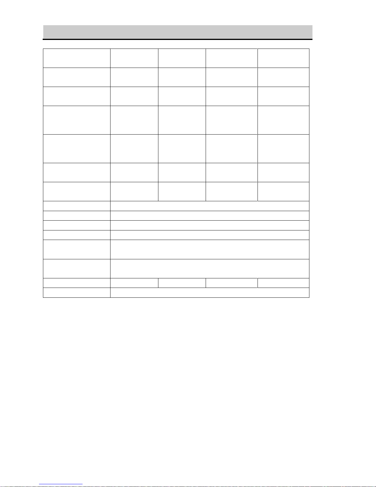
SPECIFICATION
Model no.
TC-N028M
TC-N028R
TC-N028MH
TC-N028RH
TC-T028M
TC-T028R
TC-T028MH
TC-T028RH
Cooling capacity
8500 BTU
2491 W
8500 BTU
2491 W
10000 BTU
2930 W
10000 BTU
2930 W
Heating capacity
N/A
8500 BTU
2491 W
N/A
10000 BTU
2930 W
Power/Ampere
consumption for
cooling*
1010W/ 4.5A
1010W/ 4.5A
1235W/ 5.5A
1235W/ 5.5A
Power/Ampere
consumption for
heating*
N/A
870W/ 3.9A
N/A
1175W/ 5.2A
Air volume (max.
speed)
350 m3/h
350 m3/h
350 m3/h
350 m3/h
Humidity removal
capacity
1.2L/hr
1.2L/hr
1.5L/hr
1.5L/hr
Power supply
220-240V~, 50Hz/1phase
Compressor
rotary
Refrigerant
R410a
Fan speed
2
Timer
Mechanical type: 8 hours
Electronic type: 12 hours
Working temperature
Cooling: 18 ~ 32oC
Heating: 5 ~ 27oC
Net Weight
30 kg
30 kg
32 kg
32 kg
Dimension
430 x 403 x 753 mm (WxDxH)
REMARK:
1. Measuring condition for above is as per EN 14511 : DB=35°C , WB=24°C
*DB = temperature of dry bulb = room temperature, WB = temperature of wet bulb =
relative humidity.
2. Test condition for data in our rating label is as per safety regulation: EN 60335-2-40
3. Current & Fuse : F2L250V or T2L250V
1
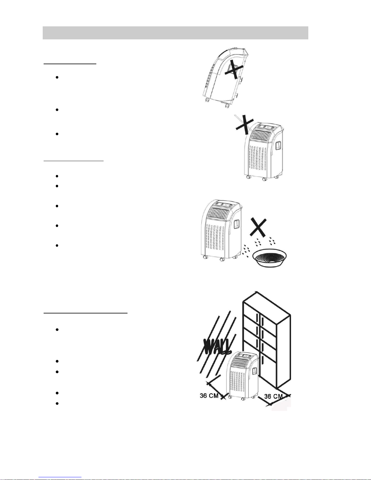
BEFORE USE
GENERAL SAFETY
ONLY USE IN THE UPRIGHT POSITION
ON A FLAT LEVEL SURFACE AND AT
LEAST 50cm FROM ANY OBJECTS (Fig
1 & 4).
DO NOT PLACE OBJECTS ON THE UNIT
OR RESTRICT AIR INLET / OUTLET (FIG.
2).
CLOSELY SUPERVISE ANY CHILDREN
AND PETS WHEN UNIT IS IN USE.
ELECTRICAL SAFETY
FOR INDOOR USE ONLY.
SWITCH OFF AND UNPLUG WHEN NOT
IN USE.
DO NOT USE IN HUMID OR WET
ENVIRONMENTS (FIG 3)
DO NOT PULL THE UNIT ALONG BY THE
CORD.
IF THE SUPPLY CORD IS DAMAGED, IT
MUST BE REPLACED BY AN
ELECTRICIAN OR SIMILARLY
QUALIFIED PERSON, TO AVOID
HAZARD.
FOR MAXIMUM EFFICENCY
Do not exceed the recommended
room size 50m3 (typically 20m2 floor
area)
Close doors and windows
Keep curtains of blinds closed
during the sunniest part of the day
Keep filters clean
Once room has reached the
desired conditions, reduce
temperature and ventilation settings
2
FIG. 1
FIG.2
FIG.3
FIG.4
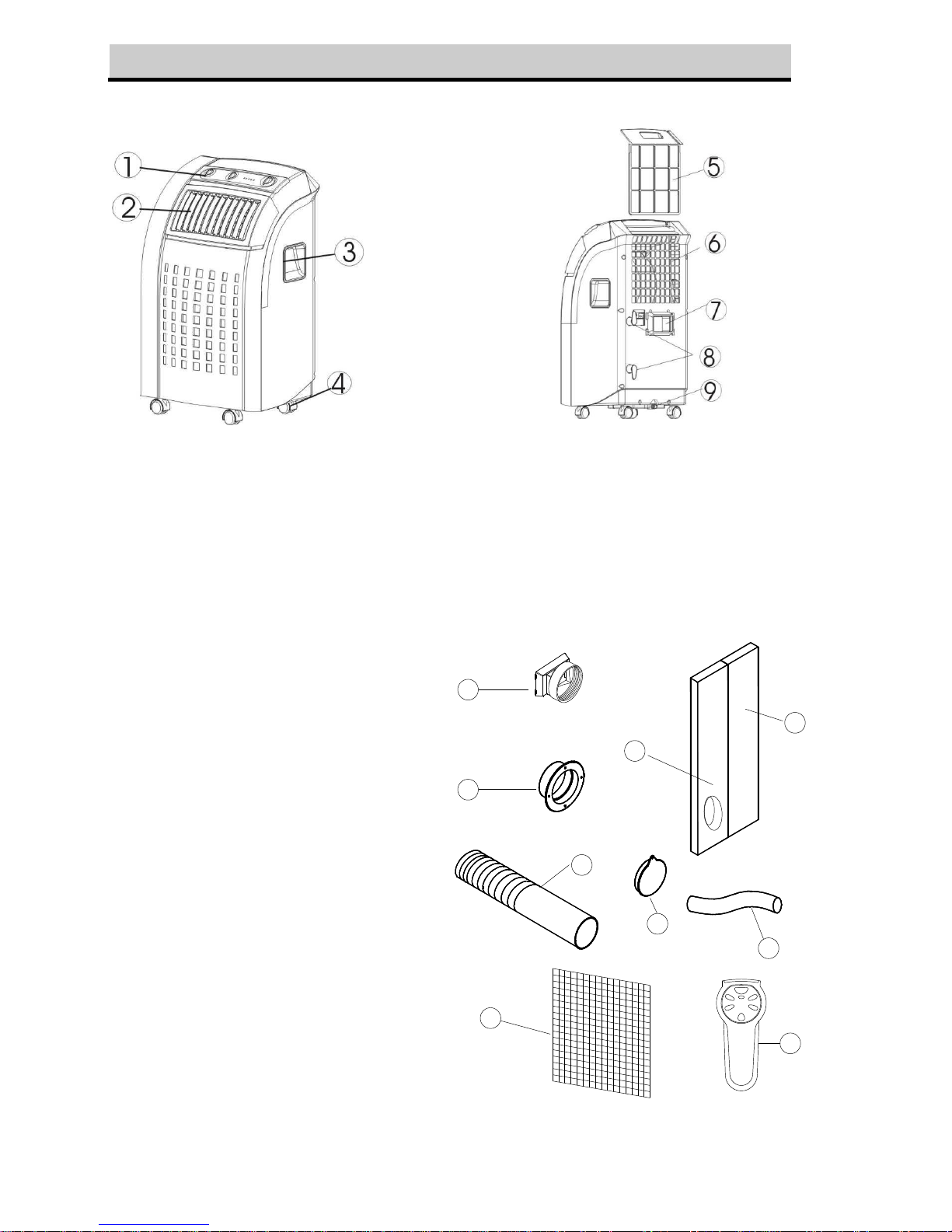
PARTS
Front
Back
1. Control Panel
2. Air outlet
3. Carrying handle
4. Caster
5. Air filter
6. Air inlet
7. Exhaust air outlet
8. Cord storage
9. Water stopper / drainage point
Accessories
10. Inward adaptor - for
insertion over hose and
into back of the air
conditioner.
11. Outward adaptor - for
insertion over hose and
into foam strip (or into
hole in the
wall/window).
12. Exhaust hose
13. Foam strip - for filling
the open window space
and with hole for
connection to exhaust
hose.
14. Foam strip - for filling
the open window space
15. Round cap for filling the
hole in wall/window.
16. Drain tube for
continuous drainage
17. Active carbon filter
18. Remote control (for
electronic type only)
17
13
14
10
11
15
18
12
16
3
INSTALLATION
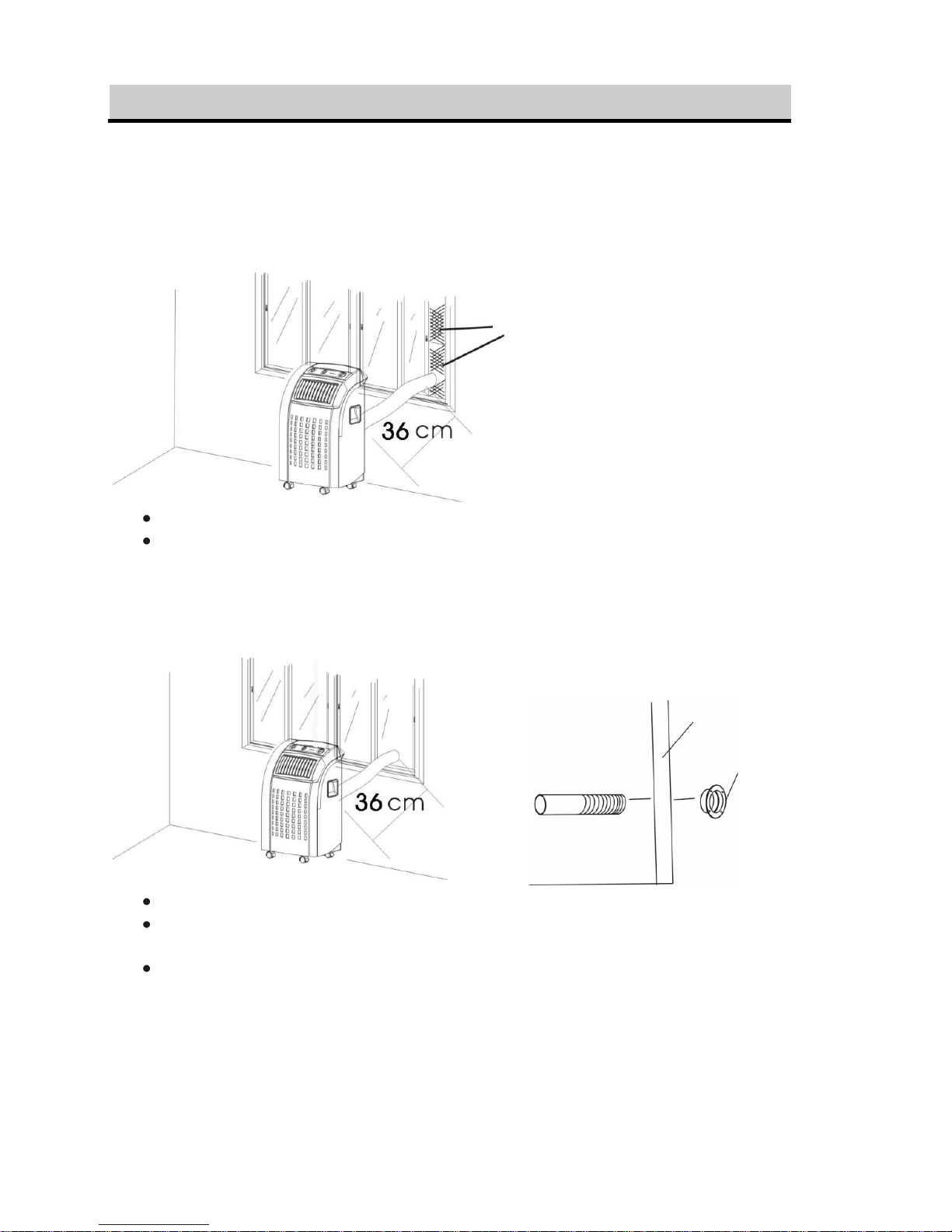
Installation of the exhaust pipe
The unit is a portable air conditioner that may be moved from room to room.
1. Using the foam strips
FIG.5
Offer foam strips to the window gap and cut to size if necessary.
Feed exhaust hose through the foam strip and insert strip into window gaps as
shown and slide window across so that foam is held securely. This technique
may also be used for sash windows. Note: Take care to maintain protection
against intruders
2. Using the adaptor
FIG.6
FIG.7
Cut a 130mm diameter hole in the wall or window.
Feed exhaust hose through the window or wall and attach the threaded adaptor
from the outside as shown.
When not in use, plug the hole with the cover provided.
4
Foam strips
Wall or Window
Outward adaptor
 Loading...