

Page 1
Owner’s Operating Instruction Manual
Saito™ 4-Stroke Gasoline Engines
Model FG-14C, FG-17 & FG-21
Model FG-30B, FG-36B & FG-40
Version 2012
Page 2
2
This manual describes the engine and its general operating procedures. For mounting and control, see the
instruction manual for the model airplane. Some suggestions are included in this manual for mounting the engine
using the included motor mount.
For proper heat transfer, it is important to use a metal motor mount when mounting these engines in a model
aircraft.
The engine is designed for use on a model radio control airplane. If it is used for any other purpose, we cannot be
responsible for its reliability or safety.
• Always use genuine Saito parts for replacements.
• Be sure to check the propeller before each flight. If it is damaged, replace the propeller with a new one.
• If the propeller hits something while the engine is in operation, immediately stop the engine and check for
damage.
• Start the engine on a flat surface free of stones or other debris.
• When mixing fuel, or operating the engine, do so in a well-ventilated area.
NOTICE
All instructions, warranties and other collateral documents are subject to change at the sole discretion of
Horizon Hobby, Inc. For up-to-date product literature, visit horizonhobby.com and click on the support tab for
this product.
Meaning of Special Language
The following terms are used throughout the product literature to indicate various levels of potential harm when
operating this product:
NOTICE: Procedures, which if not properly followed, create a possibility of physical property damage AND a
little or no possibility of injury.
CAUTION: Procedures, which if not properly followed, create the probability of physical property damage AND
a possibility of serious injury.
WARNING: Procedures, which if not properly followed, create the probability of property damage, collateral
damage, and serious injury OR create a high probability of superficial injury.
WARNING: Read the ENTIRE instruction manual to become familiar with the features of the product
before operating. Failure to operate the product correctly can result in damage to the product, personal
property and cause serious injury.
This is a sophisticated hobby product. It must be operated with caution and common sense and requires some
basic mechanical ability. Failure to operate this Product in a safe and responsible manner could result in injury
or damage to the product or other property. This product is not intended for use by children without direct adult
supervision. Do not attempt disassembly, use with incompatible components or augment product in any way
without the approval of Horizon Hobby, Inc. This manual contains instructions for safety, operation and maintenance. It is essential to read and follow all the instructions and warnings in the manual, prior to assembly, setup
or use, in order to operate correctly and avoid damage or serious injury.
Age Recommendation: Not for children under 14 years. This is not a toy.
Safety Warnings and Precautions
Page 3

3
• Never return unused fuel from the fuel tank back into
the fuel container.
• Never attempt to repair or modify a propeller beyond
its intended use.
• Never handle model engines, mufflers and/or tuned
pipes until they have had time to cool. They become
extremely hot when in use.
• Never use hands, fingers, or any other body part to
stop the propeller.
• Never throw any object into a propeller to stop it.
• Never run the engine in the vicinity of loose small
objects, such as gravel or sand, to avoid the propeller
uncontrollably throwing such materials.
• Never wear loose clothing or a loose neckstrap when
operating your model engine as these items could
become entangled in the propeller.
• Never have loose objects such as screwdrivers,
pencils etc. in your pockets when operating your
model engine. These could fall into the propeller.
• Never allow fuel to come into contact with eyes
or mouth. Gasoline and other fuels used in model
engines are poisonous.
• Always ensure spectators, especially children, are at
least 30 feet away when running the engine.
• Always ensure that the propeller is securely attached
to the engine shaft and all retaining fasteners are
tightened properly before EACH flight. Use of blue
threadlock to tighten nuts is advisable.
• Always keep small parts out of the reach of children
as they can be choking hazards.
• Always secure the airplane before powering the
engine.
• Always keep your face and body away from the path
of the propeller blades when starting or running your
engine.
• Always stand behind the propeller when making
carburetor adjustments.
• Always wear safety glasses or goggles when starting
and running your engine.
• Always keep your fuel in a safe place well away from
sparks, heat or anything that can ignite.
• Always ensure the aircraft is secure and will not
move once the engine is started.
• Always rebind your transmitter to your receiver(s)
after setup and before first flight.
• Always ensure the throttle failsafe is set to low
throttle in your transmitter.
• Always perform a range check prior to flight.
• Always cut off the fuel supply (pinch or disconnect
the fuel line to the carburetor) or use the throttle
linkage to shut off the air in order to stop the engine.
• Always ensure gasoline and fuel is stored in a
clearly marked container well away from the reach
of children.
• Always mount the engine securely on a bench mount
or high-quality engine mount.
• Always use the correct size and pitch of propeller for
your engine. Refer to Propeller Chart in this manual.
• Always confirm proper balance of your propeller prior
to installation of the engine. Failure to do so could
cause damage to the engine and/or the airframe.
• Always utilize an electric starter to start your engine.
• Always discard any propeller that is nicked,
scratched, cracked or damaged in any way.
• Always run your model engine in a well-ventilated
area. Model engines produce possibly harmful
carbon monoxide fumes.
• Always store your fuel safely in a sealed, waterresistant container.
• Always store fuel in a cool, dry location. Do not
allow fuel containers to come in direct contact with
concrete, as the fuel may absorb moisture.
• Always responsibly discard fuel if there is
condensation and/or water inside the fuel container.
Model engines produce a substantial amount of power and can create unsafe situations if not used correctly.
Always use common sense and observe all safety precautions when operating, handling or performing any
procedure involving your engine. Failure to follow safety precautions could result in serious injury and property
damage.
Page 4

4
Table of Contents
Safety Warnings and Precautions ..........................................................2
Introduction to the Saito Gasoline 4-Stroke Engines .............................................4
Components .........................................................................5
FG-14C/FG-17/FG-21 Engine Instructions .................................................5
Engine Mounting and Muffler Attachment ...................................................5
Propeller ........................................................................... 6
Fuel ..............................................................................7
Fuel Tank and Plumbing ................................................................7
Spark Plug .........................................................................8
Carburetor .........................................................................8
Preparation Before Starting the Engine (prior to break-in) ........................................ 9
Starting the Engine (assuming the engine is mounted in an aircraft) ...............................10
Break-in ..........................................................................11
General Operating Procedures (to ensure the long life of the engine) ..............................11
Normal Operation, Maintenance and Additional Information .....................................12
Setting the Needle Valves in the Gas 4-Stroke Engines ........................................12
FG-30B/FG-36B/FG-40 Engine Instructions ............................................... 13
Engine Mounting and Muffler Attachment ..................................................13
Propeller .......................................................................... 14
Fuel .............................................................................15
Fuel Tank and Plumbing ...............................................................15
Carburetor ........................................................................16
Preparation Before Starting the Engine (prior to break-in) ....................................... 17
Starting the Engine (assuming the engine is mounted in an aircraft) ...............................17
Choking the Engine ..................................................................18
Running-In the Engine ................................................................18
Final Adjustment of the Carburetor .......................................................19
Troubleshooting Guide ................................................................19
Carburetor Maintenance ..............................................................20
Valve/Tappet Gap Adjustment ........................................................... 20
FG-14C/FG-17/FG-21 Dimensions, Specifications, Parts List and Exploded View .......................21
FG-30B/FG-36B/F-40 Dimensions, Specifications, Parts List and Exploded View .......................25
Warranty Information ..................................................................33
Introduction to the Saito™ Gasoline 4-Stroke Engines
The Saito four-stroke gasoline series of engines were developed to satisfy a market need for a more cost-effective
and cleaner answer to the then current glow-powered engines. Ever at the forefront of technology, Saito has led
the way many times in developing engines with large displacements in small case sizes. It seemed only natural
that they would also lead the way to a more cost-effective fuel alternative to glow-powered engines.
Page 5
5
FG-14C FG-17 FG-21 FG-30B FG-36B FG-40
Engine
3 3 3 3 3 3
Valve Adjusting
Tools
3 3 3 3 3 3
Muffler Wrench
3 3 3
Ignition SAIG14C153 SAIG17153 SAIG17153 SAIG30B153 SAIG30B153 SAIG40153
Engine Mount SAIG1495 SAI10095 SAIG2095 SAIG3095/
SAIG3695
SAIG3095/
SAIG3695
SAIG3695
Spark Plug 1/4-32;
SAIG20120
1/4-32;
SAIG20120
1/4-32;
SAIG20120
CM-6;
SAIG36120
CM-6;
SAIG36120
CM-6;
SAIG36120
Muffler SAIG1474 SAIG1474 SAIG2074 SAIG3674 SAIG3674 SAIG3674
Muffler
Manifold
SAIG8075B SAI91S75 SAI125A75 SAI120S75A/
SAIG3675
SAI120S75A/
SAIG3675
SAIG3680
Muffler Nut,
2 Pcs
SAIG8080A SAIG8080A SAI125A80 SAI120S80/
SAIG3680
SAI120S80/
SAIG3680
SAIG3680
Spark Plug
Wrench
SAIG20967 SAIG20967 SAIG20967 SAIG36969 SAIG36969 SAIG36969
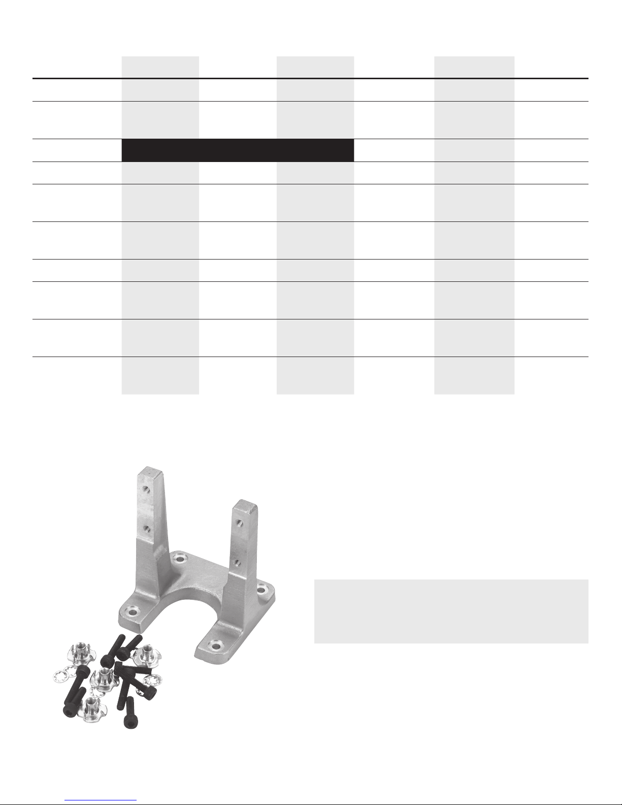
Components
Engine mount for the FG-21
Mount the FG-14C, FG-17 or FG-21 engine on aircraftgrade plywood with more than 6mm thickness or to
a mount of equivalent strength, then firmly fix with 4
bolts. We highly recommend the use of the included
Saito Motor Mount for the FG-14C (SAIG1495B), FG-17
(SAI10095) or FG-21 (SAIG2095) to mount this engine
to a model aircraft.
NOTICE: Be sure to use flat washers or a metal
plate on the reverse side of the mount to prevent the
bolts from sinking into the plywood. Before flying the
airplane, be sure to check for loose bolts.
Since this engine is equipped with a floatless carburetor
with a diaphragm pump, the direction of the cylinder in
regards to the position of the fuel tank can be upright
or inverted.
FG-14C/FG-17/FG-21 Engine Instructions
Engine Mounting and Muffler Attachment
Page 6
6
Carefully attach the throttle linkage to the engine using a ball link on the carburetor throttle arm. Make sure the
linkage is free to operate from low to high throttle. Also, confirm that the low throttle setting on the transmitter
closes the carburetor throttle barrel to the low-idle position. Adjust the length of the pushrod until full throttle
opens the carburetor throttle barrel to the fully open position and low throttle, low trim completely closes the
throttle barrel.
Throttle Linkage
Propeller
Recommended Propeller Sizes: The recommended
propeller sizes are shown in the table below. The use
of a large propeller will require care in balancing it.
Vibration will reduce performance and can result in
damage to the engine and airframe.
For break-in, Saito recommends the use of a smaller
propeller for the initial break-in and approximately 20
subsequent flights.
Diameter x Pitch (inches)
FG-14C FG-17 FG-21
13 x 8 14 x8 15 x 6–10
14 x 6–8 15 x 6–8 16 x 6–8
15 x 4 16 x 6 17 x 6
3 blade 15 x 7–9
The engine produces the maximum output when the
engine is running at about 8,500–9,200 ground rpm
for the FG-14C and 8,300–9,000 ground rpm for the
FG-17/FG-21.
Propeller and Fuel Consumption
In order to decrease fuel consumption and prolong the life of the engine, choose a propeller that maximizes rpm when
the throttle is fully open, and an airframe that performs flights at about 90% of the propeller output. If the load is large
(the diameter and pitch of the propeller is large), the air-fuel mixture will have to be rich. If the load is small, the rpm
will be high, but the fuel consumption is less due to the high-speed needle valve being leaned out more.
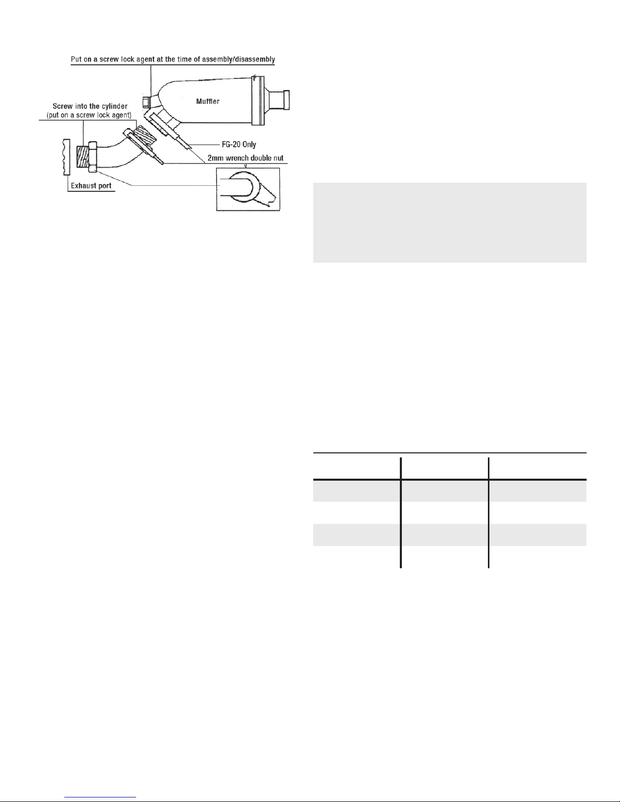
Figure 1
FG-14C = 14mm wrench
FG-21 = 17mm wrench
When you attach the muffler, use a drop of oil on the
threads to ease the assembly. Screw the exhaust
manifold into the engine exhaust port and the muffler
as far as the thread will allow (see above drawing).
Notice the use of the two wrenches used in tightening
the two nuts on the muffler/manifold connection. Use of
threadlock is recommended.
Remember to ensure cooling air passes by the engine
and muffler in a cowled environment.
NOTICE: Air is necessary to cool the engine during
operation. Make sure sufficient air circulation through
the cowling is provided. As a basic reference, the
outlet area should be 3 to 5 times the area of the
inlet area to provide adequate cooling.
Page 7
7
Fuel
• Mix a ratio of gasoline to oil of 20:1 for break-in and
continuous operation on all engines.
• A mixture of high-quality 91 octane unleaded
gasoline and a reliable, high-quality 100% synthetic
oil for 2-cycle engines must be used. We recommend
Evolution Oil (EVOX1001Q).
With the use of an oil mixture of 20:1, it is normal to
see a slight amount of carbon buildup on the exhaust
valve itself. This is why it is important that you use a
high-quality synthetic oil instead of standard 2-stroke
oil you may be using in your 2-stroke gas engine.
Although these 2-stroke oils work well in their intended
applications, they can cause a build up of a gummy
residue on the exhaust valve in a 4-stroke gas engine.
This may require service for your engine if the exhaust
valve begins to stick and not seal properly.
The high-quality Evolution oil we recommend will still
build up a slight amount of carbon, but we have found
that this build up is easily flaked off during normal
operation of the engine. It will not create the typical
gummy build up.
• Remember to use caution in the storage, use and
transport of gasoline.
• Since commercial gasoline has many impurities,
please be sure to use a reliable fuel filter (SAI50109
or HAN143) in your fuel system.
• The recommended fuel tubing is Evolution
®
Gasoline
Fuel Tubing (EVOA102). DO NOT use a silicone
rubber fuel line for the engine, the fuel tank, or your
fueling system.
• The use of fuel with up to 10% ethanol has been
tested and found to work fine.
• The use of a filtered clunk or sintered clunk on the
fuel pick up line is required. The Evolution In-tank
Felt Filter/Clunk (EVOA106) is designed specifically
for gas engine operation.
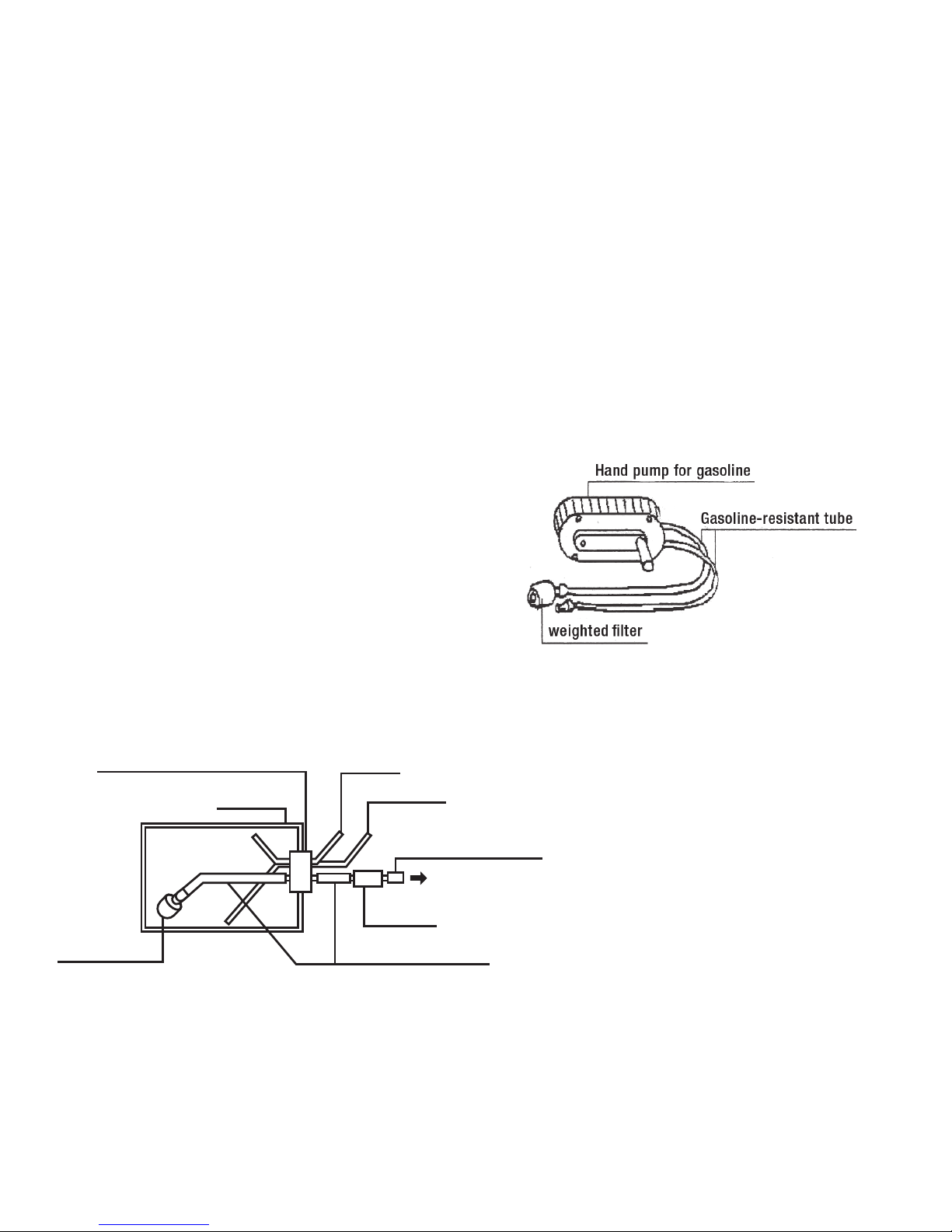
Figure 2
Figure 3
Filtered Weight
Gasoline-resistant Rubber Cap
Fuel Tank
Vent Tube
Fueling Tube
Gasoline-resistant Tube
Gasoline-resistant Tube
Carb Nipple
Fuel Filter
Be sure to include a reliable fuel filter in
your fuel system. The drawing to the left
suggests the use of a fuel feed line and
an air intake line. Also, be sure to use a
fuel line that is compatible with gasoline.
Fuel Tank and Plumbing
Page 8
8
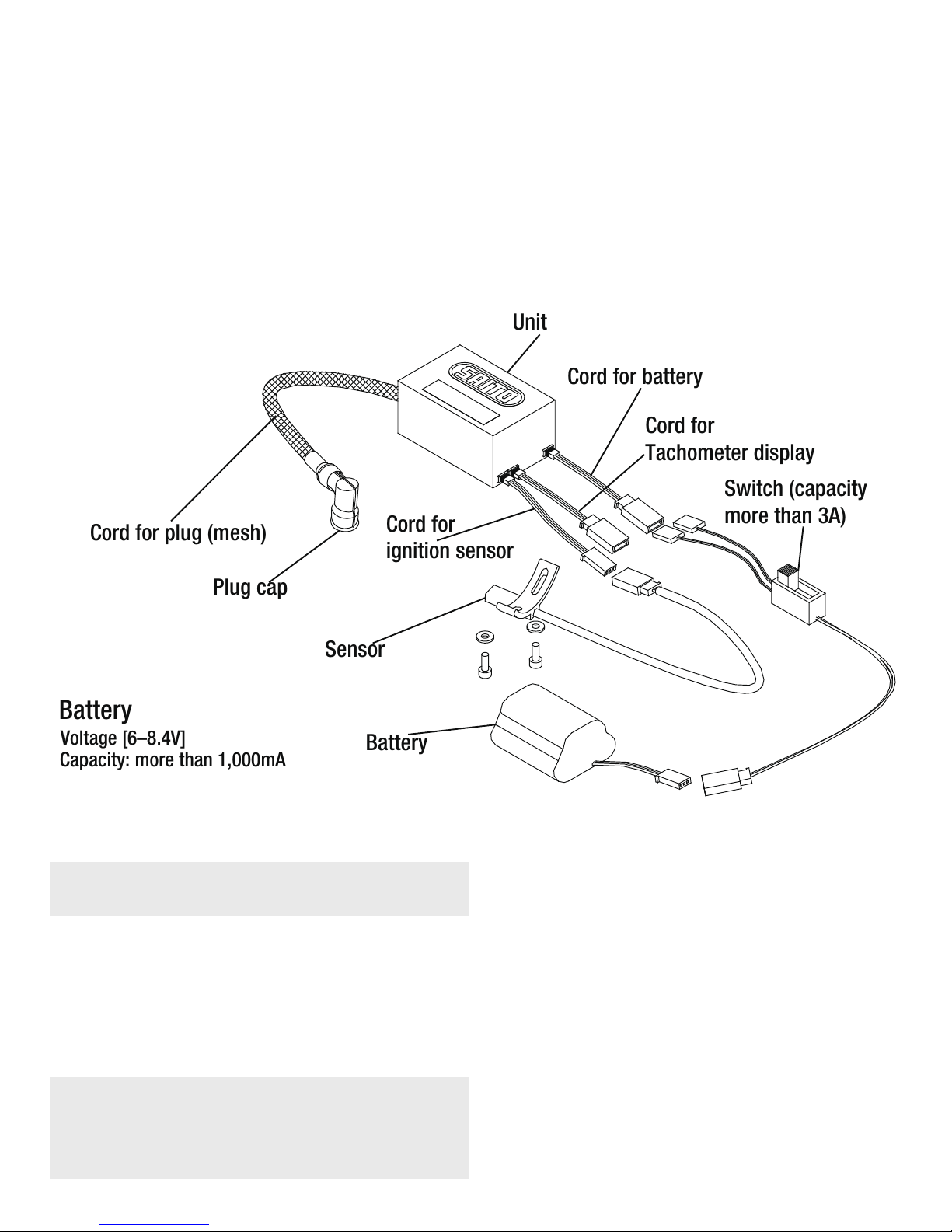
Saito gasoline four-stroke engines come with the Saito
ignition system, composed of the ignition unit, a cord
for the sensor (black and white), insulated plug cap,
and cord (black and red) for connection to a battery (not
included). You will also need to secure an on/off switch
(safety switch system). The switch must carry a rating
of 3 amps.
Be sure to mount the ignition system in a location near
the engine and away from the receiver to prevent any
unwanted interference. Please refer to the diagram
below.
The Saito ignition has an operating voltage from
4.8–9.0 volts. Saito recommends the use of a 5-cell
Ni-Cd/Ni-MH battery or a 2-cell Li-Po/Li-Ion/Li-Fe with
a minimum of 1000mAh. The recommended battery is
the Team Orion
®
Avionics Li-Fe Receiver Pack 1300mAh
6.6V (ORI60503).
1/4-32
Spark gap = .4 to .5mm (.016 to .020 in)
The FG-14C, FG-17 and FG-21 come with the Saito
1/4-32 spark plug (SAIG20120). When needed,
replace with identical plugs.
Ignition System
Spark Plug
Carburetor
The carburetors used on gasoline four-stroke engines
are exclusive to Saito. Since they have a negative
pressure type fuel pump, the engine can be mounted in
any position.
NOTICE: Always remove fuel from the carburetor
after flight. Not doing so will result in rubber engine
components (such as the diaphragm) deteriorating
over time, causing loss of engine performance.
After a flying session, it is best to remove any fuel
remaining in the carburetor by disconnecting the fuel
line and running the engine until it is dry.
Do not needlessly disassemble the carburetor.
If you experience problems with the carburetor, return it
to the Saito Horizon Service Center.
Cord for plug (mesh)
Plug cap
Sensor
Battery
Cord for
ignition sensor
Cord for
Tachometer display
Cord for battery
Switch (capacity
more than 3A)
Unit
Battery
Voltage [6–8.4V]
Capacity: more than 1,000mA
Figure 4
Page 9
9
Preparation Before Starting the Engine
(prior to break-in)
• Mount the engine on a strong, flat test bench or on
the aircraft (in either case, the engine should be
secured so it is immobile).
• Check to make sure the carburetor will open and
close completely.
• Check the wiring of the ignition system to make sure
it is connected correctly and securely.
• Make sure the fuel line is connected securely to the
carburetor.
• For break-in, use a fuel/oil mix ratio of 20:1.
• FG-14C: Mount a 14 x 6 plastic or wood propeller.
Be sure it has been balanced. Check the tightness
after every flight.
• FG-17: Mount a 14 x 8 plastic or wood propeller. Be
sure it has been balanced. Check the tightness after
every flight.
• FG-21: Mount a 15 x 6 plastic or wood propeller. Be
sure it has been balanced. Check the tightness after
every flight.
• It is suggested you employ a spinner when using an
electric starter. Check the tightness after every flight.
• Use a tachometer to determine proper needle valve
settings of the engine.
• Be sure to connect a gasoline-proof line to the
breather nipple to vent oil from the airframe.
• Check the battery of the electric starter to make sure
it is fully charged.
• Be sure to use a safety on/off switch from the battery
to the ignition.
WARNING: Always keep all spectators,
especially children, are at least 30 feet away
when running or starting the engine.
WARNING: Always ensure the aircraft is
secure and cannot move when preparing to
start the engine. Failure to do so could cause
property damage and serious injury.
To best understand the FG-14C, FG-17 and FG-21
carburetor, you need to know what it is not.
It is not a Walbro carburetor.
It is not a glow carburetor.
As we made strides to bring cheaper gasoline power to
ever smaller engines, this uniquely designed carb was
developed because the currently available carbs from
the lawn power equipment world were way too large to
be included with our smaller powerplants.
Gasoline fuel requires a much finer atomization of the
droplets than glow fuel does. Because the amount of
fuel flowing through the engine is so much lower than
with a typical glow fuel setup (up to 60% less fuel),
maintaining a constant flow and pressure becomes even
more critical. Close inspection of the cat’s eye orifice on
the needle valve body in the FG-14C/21 carb reveals
a miniscule opening; perfectly sized for the proper
atomization of the fuel for your engine.
This new carb features a pump function designed to
provide the correct amount of fuel to the needle valve
assemblies to correctly operate the engines. It is not
designed as a fuel pump to draw fuel from a tank
mounted in the middle of your airplane. The fuel tank
needs to be mounted as close to the centerline of the
Carb assembly as possible; the same as we have had to
do for all these years with our glow engine installations.
If you stray very far from this rule, the engine will run
differently upright and inverted. This usually leads to
comments that an engine doesn’t like to run inverted,
etc., when in reality, the fuel delivery system needs to be
optimized for the engine installation being used.
The pump is actuated by the negative pressure pulses
when the intake valves are open and the engine is
drawing fuel into the cylinder. On the latest version
of the carburetor, we enlarged the area of the hole
that delivers these pulses to the pump assembly. It
has greatly improved the pumping action and has
much more tolerance of ‘less than optimum’ fuel tank
locations. But it is still not a Walbro carb and will not
draw fuel from any long distance.
Understanding the Saito Gas Carb for the FG-14C, FG-17 and FG-21
Page 10
10
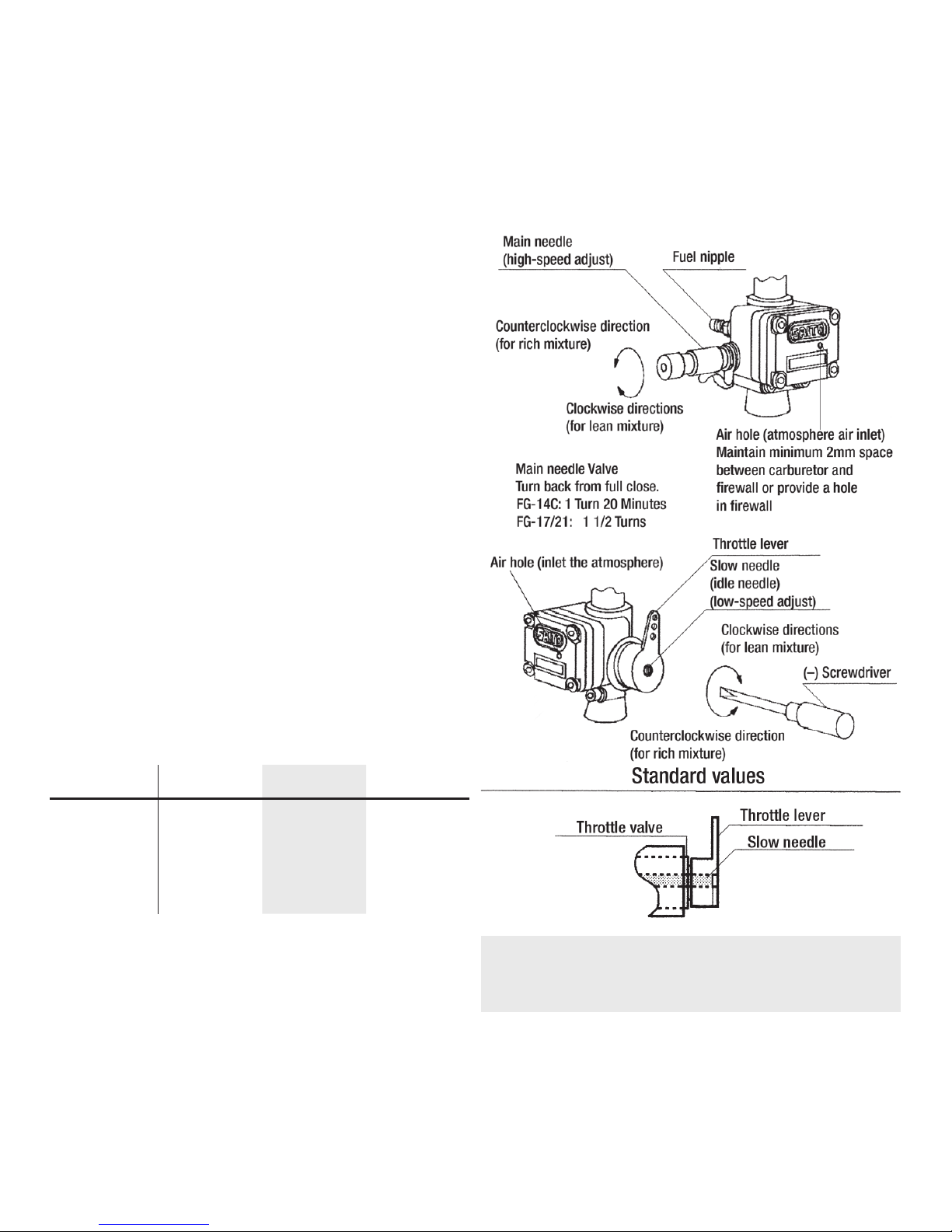
The carburetor on the Saito engine comes with the
low-speed needle adjusted to a basic setting. The
high-speed needle will need to be set by the user. The
standard carburetor settings are as follows: The highspeed needle valve is set open counterclockwise from
the fully closed position.
On the FG-14C, FG-17 and FG-21 the low-speed needle
should be set at 7-5/8 from closed.
1. Disconnect the throttle arm from the throttle pushrod.
2. Manually hold the throttle barrel closed.
3. With a small tip flat screwdriver, screw in the idle
adjustment all the way until you feel the throttle
barrel trying to rotate. The low-speed adjustment
is actually not a needle—it is a sleeve that cover/
uncovers a cat’s eye slit in the fuel supply tube.
When you run the low-speed adjustment all the way
in, the sleeve will bottom out against the fixed carb
body and force the barrel to rotate.
4. Now richen the low-speed needle by 7 turns, 35
minutes. In our experience, this will be within an 1/8
of a turn (+/–) from perfect at the low end.
5. Reconnect the throttle pushrod.
6. Once this change is made to the low end, open the
high end by 1/2 turn from where you ran it before,
restart the engine and reset the high-end needle
valve. Please refer to the diagrams.
The minutes listed are in reference to the minute hand
of a clock.
FG-14C FG-17 FG-21
High-speed
needle
1 turn
20 minutes
1 turn
30 minutes
1 turn
30 minutes
Low-speed
needle
7 turns
35 minutes
7 turns
35 minutes
7 turns
35 minutes
Before you first start the engine, make sure the spark
plug is screwed in and tightened and that the plug
socket cap is fitted in place and fastened down properly.
Fix the ignition sensor in the proper position at the
bottom of the engine crankcase. The throttle servo
should be mounted at a distance of 8 to 12 inches from
the engine. The spark plug cable must not touch any
part of the model structure as vibration may damage
the shielded cable. If this is not practical, it will be
necessary to provide an insulation material for the cable.
The ignition unit itself should be wrapped in foam
rubber to prevent engine vibration from damaging
the electronic components. All components must be
protected from contact with engine fuel. Be sure to use
an on/off (Safety or “kill”) switch to allow the ignition to
be turned off and on.
Figure 5—FG-14C/FG-17/FG-21 Carburetor
NOTICE: Never turn the engine over with the ignition
turned on unless the spark plug is inserted in the
plug socket. This could lead to ignition damage.
Saito 4-stroke gasoline engines come with a
pumped carburetor. You do not have to choke the
engine as you normally would a 2-stroke engine.
When you are ready to start the engine, switch the
ignition on and set the throttle to a slightly high idle
speed. We highly recommend the use of an electric
starter.
Starting the Engine (assuming the engine is mounted in an aircraft)
Page 11

11
Be sure to have a helper hold the model securely.
• Turn on the transmitter first, then the receiver and
check the operation of the throttle servo and other
controls.
• Turn on the power to the ignition system.
• Using an electric starter, begin cranking the engine.
It should fire within seconds of applying the starter.
Allow the engine to idle for 30 to 45 seconds.
• If the engine does not start, even after using the
electric starter to crank the engine a second time,
open the throttle to maximum, turn off the ignition
and turn the engine over about 4 revolutions. Switch
the ignition on again and then restart the engine with
the throttle at a fast idle position.
• If the engine still will not start, unscrew the spark
plug and check its contacts. Clean any possible
excess fuel (an indication of engine flooding) and
screw it in again. Further starting should only be
done with the throttle at idle position. If the plug is
dry, probably not enough fuel has been drawn into
the carburetor. If that is the case, check the fuel feed
and then return to the instructions above.
We strongly urge the use of a tachometer to check rpm
readings when breaking in the engine.
After starting and warming the engine for 30 to 45
seconds, adjust as follows: for initial break-in, do not
exceed 4,000 rpm for the first 10 minutes of operation.
This allows all the parts to mate properly with good
lubrication.
WARNING: Before adjusting the carburetor,
you MUST stop the engine. Failure to do so
will cause the propeller to continue to move if
the engine is not stopped, which could result
in serious injury.
Subsequent runs may be made while slightly leaning out
the mixture with each tank full of fuel. Forty minutes is
considered sufficient time for normal break-in prior to
the first flight.
Conrods
Saito has developed a specific aluminum alloy and manufacturing process that allows them to eliminate the need
for a separate bearing material in the lower end of their conrods. The benefit of this is you never have to worry about
the bearing material (usually bronze oilite) rotating in the conrod and blocking off the critical bearing lubrication
holes machined into the bottom of the conrod. This process also allows for smaller crankcases and smaller airplane
applications. It also creates the requirement for the 20:1 oil mixture in our gasoline powered engines.
Do not skip this step. You risk seizing the conrod to the crankshaft.
The most important component to break-in on all Saito 4-stroke engines, and especially the gasoline engines, is
the conrod to crankshaft interface. The break-in process required for all Saito engines is designed to break-in the
conrod to crankshaft interface more than to seat the ring. The ring will seat gradually over time and the engine will
develop more and more power. Ensure the conrod is treated correctly from the beginning.
Break-in
• Do not operate the engine with a “lean” mixture.
• Regularly check all screws and nuts on both the engine and muffler.
• After every 1 to 2 hours of operation, valve adjustment may be necessary. Adjust the valves as shown in the
Engine Maintenance and Valve/Tappet Adjustment Sections.
• Saito engines are equipped with a “breather” nipple. It is recommended that a length of PFM type tubing
(EVOA102) tubing be attached to this crankcase breather nipple and routed away from the engine compartment
so the excess oil can be expelled outside of the aircraft.
General Operating Procedures (to ensure the long life of the engine)
Page 12

12
Normal Operation, Maintenance and Additional Information
• Be sure to do a range check before flying your
model. It would be wise to do the range check with
the engine running and without it running. As a
simple noise check, after the engine is started, do
the normal range check your radio manufacturer
recommends.
• Be sure to charge the ignition battery and radio
system battery before the first flight of the day.
• To discharge the waste oil, connect a gasoline-proof
line from the breather nipple on the crankcase and
vent it outside of the aircraft.
• Lubrication of the piston, connecting rod, bearings
and cam gear is blow-by lubrication, where the oil in
the fuel goes into the crankcase from the clearance
between the cylinder and the piston. Engine life is
directly affected by the property of the fuel/oil mix.
Please use reliable oil.
• Running the engine too lean causes heat; be sure
to run the engine slightly “rich” from peak. Running
too lean will cause “knocking” or engine failure and
has an adverse effect on the connecting rod and the
cam gear.
• Adjustment of the tappet is described in the “Valve/
Tappet Gap Adjustment” section.
• When attaching an exhaust pipe to the cylinder or
attaching a propeller nut, the use of threadlock is
recommended.
• Sometimes it is helpful to tighten an exhaust nut, etc.
when hot.
• When finished flying for the day, be sure to remove
fuel from the carburetor and the fuel tank.
• If the engine will not be operated for a long period
of time, remove the plug, rear cover, cylinderhead cover, etc., then clean thoroughly and re-oil.
Assemble them in the original condition and place in
a plastic or air-tight container.
Setting the Needle Valves in the Gas 4-Stroke Engines
Use a Tachometer
When setting any 4-stroke engine, it is critical that a
tachometer is used in setting the needle valves. It is
near impossible to set them properly by ear. A good
quality tachometer will go a long way towards improving
your usage of these engines and makes the experience
even more enjoyable. Make the investment.
Set the High-Speed Needle First
A general starting point for the high-speed needle on
the FG-14C carb is 1 turn 20 min. and the FG-17/FG21 carb is 1 turn 30 min.
1. Start the engine. Using your tachometer to gradually
lean the high-speed needle valve until the engine
reaches its peak rpm.
a. This will take some patience because it will take a
few seconds after making a 1 click needle change
to register an increase.
b. As you hit the perfect peak setting, you will notice
that there will be no rpm change.
c. Continue to lean the engine until you notice an rpm
decrease. It is only once you have experienced the
rpm decrease can you be sure you have actually
reached the peak setting.
2. Once you are sure that you are on the lean side richen
(open) the high-speed needle back to the peak rpm.
3. Open the high-speed needle 2 clicks rich from your
confirmed peak and leave it there. You will likely
notice a small rpm difference on your tachometer, but
you will not likely be able to hear this drop in rpm.
Set the Low-Speed Needle
On the FG-14C, FG-17 and FG-21 the low-speed needle
should be set at 7 5/8 from closed.
1. Disconnect the throttle arm from the throttle pushrod.
2. Manually hold the throttle barrel closed.
3. With a small tip flat screwdriver, screw in the idle
adjustment all the way until you feel the throttle
barrel trying to rotate. The low-speed adjustment
is actually not a needle—it is a sleeve that covers/
uncovers a cat’s eye slit in the fuel supply tube.
When you run the low-speed adjustment all the way
in, the sleeve will bottom out against the fixed carb
body and force the barrel to rotate.
4. Now richen the low-speed needle by 7 turns, 35
minutes. In our experience, this will be within an 1/8
of a turn (+/–) from perfect at the low end.
5. Reconnect the throttle pushrod.
Page 13

13
6. Once this change made to the low end, open the high end by
1/2 turn from where you ran it before. Restart the engine and
reset the high-end needle valve.
7. With the engine running and the high-speed needle
valve set as above, adjust your throttle setting to
achieve the desired idle speed.
Tip: The more your prop weighs, the lower your
achievable idle speed will be.
8. Check the transition of the engine from low-speed to
high-speed. To do this, let the engine idle for a period
of 10 seconds and then rapidly move the throttle from
low to wide open. One of three things will happen:
a. The engine will respond immediately and the
transition will be very smooth to wide open throttle.
b. The engine will stumble and gradually increase
the rpm to wide open throttle. In this case the
idle needle setting is too rich. Make a very small
adjustment to lean the needle (clockwise rotation)
and try again. Continue to do this until you achieve
an immediate response from the engine.
c. The engine will abruptly quit when the throttle
is opened. This indicates a too-lean low-speed
setting. Open the low-speed needle valve a small
amount (counterclockwise) and try again. Continue
to do this until you achieve an immediate response
from the engine.
Recheck the High-Speed Needle Valve
Setting
You need to go back and recheck the high-speed
needle valve setting again as described above after
adjusting the low-speed setting. Because of the design
of the needle assembly, adjusting the low-speed needle
actually affects the size of the fuel aperture and can
affect the high-speed needle setting.
Enjoy Your New Engine
Once you have set your needle valves the final tuning
will occur in the air. Listen carefully to your engine while
it is running.
• If the rpm starts to drop a couple of minutes into the
flight, or when you climb the airplane, your highspeed needle is a bit lean. Land as soon as you can
and richen the high-speed needle settings a couple
of clicks and take off again.
• If during flight your engine has good power but
occasionally sounds like it ‘misses’, this is a good
indication that you are running the engine too rich.
The next time you land, lean the engine out one click
at a time until you are happy with the performance
in the air.
FG-30B/FG-36B/FG-40 Engine Instructions
Engine mount for the FG-36B
Mount the FG-30B,FG-36B or FG-40 engine on
aircraft-grade plywood with more than 10mm of
thickness or to a mount of equivalent strength, then
firmly fix with 4 bolts. We highly recommend the use of
the Saito Motor Mount for the FG-30B (SAIG3095) or
FG-36B/40 (SAIG3695) to mount this engine to a model
aircraft.
NOTICE: Be sure to use flat washers or a metal
plate on the reverse side of the mount to prevent the
bolts from sinking into the plywood. Before flying the
airplane, be sure to check for loose bolts.
Since this engine is equipped with a floatless carburetor
with a diaphragm pump, the direction of the cylinder in
relation to the position of the fuel tank can be upright
or inverted.
Engine Mounting and Muffler Attachment
Page 14

14
Throttle Linkage
Carefully attach the throttle linkage to the engine using a ball link on the carburetor throttle arm. Make sure the
linkage is free to operate from low to high throttle. Also, confirm that the low-throttle setting on the transmitter
closes the carburetor throttle barrel to the low-idle position. Adjust the length of the pushrod until full throttle
opens the carburetor throttle barrel to the fully open position and low throttle, low trim completely closes the
throttle barrel.
Recommended Propeller Sizes: The recommended
propeller sizes are shown in the table below. The use
of a carbon fiber propeller is highly recommended.
The use of a large propeller requires care in balancing
it. Vibration reduces performance and can result in
damage to the engine and airframe.
For break-in, Saito recommends the use of a smaller
propeller for the initial break-in and approximately 20
subsequent flights.
Diameter x Pitch (inches)
FG-30B FG-36B FG-40
16 x 8–10 17 x 10–13 17 x 10–13
17 x 6–8 18 x 8–10 18 x 8–10
18 x 6 19 x 8–10 19 x 8–10
20 x 8 20 x 8
The FG-30B, FG-36B and FG-40 engines produce
maximum output when the engine is running at about
8,300–9,000 rpm.
Propeller and Fuel Consumption
Propeller
In order to decrease fuel consumption and prolong the life of the engine, choose a propeller that maximizes rpm when
the throttle is fully open, and an airframe that performs flights at about 90% of the propeller output. If the load is large
(the diameter and pitch of the propeller is large), the air-fuel mixture will have to be rich. If the load is small, the rpm
will be high, but the fuel consumption is less due to the high-speed needle valve being leaned out more.
Figure 1
FG-30B/FG-36B/FG-40 = 19mm wrench
When you attach the muffler, use a drop of oil on the
threads to ease the assembly. Screw the exhaust
manifold into the engine exhaust port and the muffler
as far as the thread will allow (see above drawing).
Notice the use of the two wrenches used in tightening
the two nuts on the muffler/manifold connection. Use of
threadlock is recommended.
Remember to ensure cooling air passes by the engine
and muffler in a cowled environment.
NOTICE: Air is necessary to cool the engine during
operation. Make sure sufficient air circulation through
the cowling is provided. As a basic reference, the
outlet area should be 3 to 5 times the area of the
inlet area to provide adequate cooling.
Page 15

15
Fuel
• Mix a ratio of gasoline to oil of 20:1 for break-in and
continuous operation on all engines.
• A mixture of high-quality 91 octane unleaded
gasoline and a reliable, high-quality 100% synthetic
oil for 2-cycle engines must be used. We recommend
Evolution Oil (EVOX1001Q).
With the use of an oil mixture of 20:1, it is normal to
see a slight amount of carbon buildup on the exhaust
valve itself. This is why it is important that you use a
high-quality synthetic oil instead of standard 2-stroke
oil you may be using in your 2-stroke gas engine.
Although these 2-stroke oils work well in their intended
applications, they can cause a build up of a gummy
residue on the exhaust valve in a 4-stroke gas engine.
This may require service for your engine if the exhaust
valve begins to stick and not seal properly.
The high-quality Evolution oil we recommend will still
build up a slight amount of carbon, but we have found
that this build up is easily flaked off during normal
operation of the engine. It will not create the typical
gummy build up.
• Remember to use caution in the storage, use and
transport of gasoline.
• Since commercial gasoline has many impurities,
please be sure to use a reliable fuel filter (SAI50109
or HAN143) in your fuel system.
• The recommended fuel tubing is Evolution
®
Gasoline
Fuel Tubing (EVOA102). DO NOT use a silicone
rubber fuel line for the engine, the fuel tank, or your
fueling system.
• The use of fuel with up to 10% ethanol has been
tested and found to work fine.
• The use of a filtered clunk or sintered clunk on the
fuel pick up line is required. The Evolution In-tank
Felt Filter/Clunk (EVOA106) is designed specifically
for gas engine operation.
Figure 2
Fuel Tank and Plumbing
Figure 3
Filtered Weight
Gasoline-resistant Rubber Cap
Fuel Tank
Vent Tube
Fueling Tube
Gasoline-resistant Tube
Gasoline-resistant Tube
Carb Nipple
Fuel Filter
Be sure to include a reliable fuel filter in your
fuel system. The drawing to the left suggests
the use of a fuel feed line and an air intake
line. Also, be sure to use a fuel line that is
compatible with gasoline.
Page 16

16
Ignition System
Saito gasoline four-stroke engines come with the Saito
ignition system, composed of the ignition unit, a cord
for the sensor (black and white), insulated plug cap,
and cord (black and red) for connection to a battery (not
included). You will also need to secure an on/off switch
(safety switch system). The switch must carry a rating
of 3 amps.
Be sure to mount the ignition system in a location near
the engine and away from the receiver to prevent any
unwanted interference. Please refer to the diagram
below.
The Saito ignition has an operating voltage from
4.8–9.0 volts. Saito recommends the use of a 5-cell
Ni-Cd/Ni-MH battery or a 2-cell Li-Po/Li-Ion/Li-Fe with
a minimum of 1000mAh. The recommended battery is
the Team Orion Avionics Li-Fe Receiver Pack 1300mAh
6.6V (ORI60503).
Cord for plug (mesh)
Plug cap
Sensor
Battery
Cord for
ignition sensor
Cord for
Tachometer display
Cord for battery
Switch (capacity
more than 3A)
Unit
Battery
Voltage [6–8.4V]
Capacity: more than 1,000mA
Figure 4
NGK-CM6
Spark gap = .7 to .8mm (.024 to .028 in)
NGK-CM6 (SAIG36120) is the standard-equipped
plug with the FG-30B, FG-36B and FG-40. When
needed, please replace with identical plugs.
The carburetors used on gasoline four-stroke engines
are exclusive to Saito. Since they have a negative
pressure type fuel pump, the engine can be mounted in
any position.
NOTICE: Always remove fuel from the carburetor
after flight. Not doing so will result in rubber engine
components (such as the diaphragm) deteriorating
over time, causing loss of engine performance.
After a flying session, it is best to remove any fuel
remaining in the carburetor by disconnecting the fuel
line and running the engine until it is dry.
Do not needlessly disassemble the carburetor.
If you experience problems with the carburetor, return it
to the Saito Horizon Service Center.
Spark Plug
Carburetor
Page 17

17
• Mount the engine on a strong, flat test bench or on
the aircraft (in either case, the engine should be
secured so it is immobile).
• Check to make sure the carburetor will open and
close completely.
• Check the wiring of the ignition system to make sure
it is connected correctly and securely.
• Make sure the fuel line is connected securely to the
carburetor.
• For break-in, use a fuel/oil mix ratio of 20:1.
• FG-40: Mount an 18 x 8 or 19 x 8 carbon fiber
propeller such as a Bolly or Mejzlik. Be sure it has
been balanced. Check the tightness after every flight.
• FG-36B: Mount an 18 x 8 or 19 x 8 carbon fiber
propeller such as a Bolly or Mejzlik. Be sure it has
been balanced. Check the tightness after every flight.
• FG-30B: Mount a 17 x 6 plastic or wood propeller. Be
sure it has been balanced. Check the tightness after
every flight.
• It is suggested you employ a spinner when using an
electric starter. Check the tightness after every flight.
• Use a tachometer to prevent over-revving of the
engine.
• Be sure to connect a gasoline-proof line to the
breather nipple to vent oil from the airframe.
• Check the battery of the electric starter to make
sure it is fully charged. Be sure to use a safety on/off
switch from the battery to the ignition.
WARNING: Always keep all spectators,
especially children, at least 30 feet away
when running or starting the engine.
WARNING: Always ensure the aircraft is
secure and cannot move when preparing to
start the engine. Failure to do so could cause
property damage and serious injury.
Preparation Before Starting the Engine (prior to break-in)
Starting the Engine (assuming the engine is mounted in an aircraft)
The carburetor on the Saito engine comes adjusted
to a basic setting. This setting should be maintained
during the initial break-in runs. The standard carburetor
settings are as follows: the high-speed needle valve is
set from the fully closed position. The low-speed or idle
needle valve is set from the fully closed position. Please
refer to the diagrams.
FG-30B FG-36B FG-40
High-speed
needle
2 turns
30 minutes
2 turn
30 minutes
2 turn
30 minutes
Low-speed
needle
4 turns
15 minutes
4 turns
15 minutes
4 turns
15 minutes
Before you first start the engine, make sure the spark
plug is screwed in and tightened, and that the plug
socket cap is fitted in place and fastened down properly.
Fix the ignition sensor in the proper position at the
bottom of the engine crankcase. The throttle servo
should be mounted at a distance of 8 to 12 inches from
the engine. The spark plug cable must not touch any
part of the model structure, as vibration may damage
the shielded cable. If this is not practical, it will be
necessary to provide an insulation material for the cable.
The ignition unit itself should be wrapped in foam
rubber to prevent engine vibration from damaging
the electronic components. All components must be
protected from contact with engine fuel. Be sure to use
an on/off (Safety or “kill”) switch to allow the ignition to
be turned off and on.
Figure 5—FG-30B/FG-36B/FG-40 Carburetor
Counter-clockwise direction
(for rich mixture)
Clockwise direction
(for lean mixture)
Clockwise direction
(for lean mixture)
Counter-clockwise direction
(for rich mixture)
High-Speed Needle Valve
Low-Speed Needle Valve
Ball-joint for linkage
Throttle lever
NOTICE: Never turn the engine over with the ignition
turned on unless the spark plug is inserted in the
plug socket. This could lead to ignition damage.
Page 18

18
Choking the Engine
The proper way to choke the carbuerator that comes
with your FG-30B/36B/40 engine is:
1. Make sure the ignition is off.
2. Open the throttle 100%
3. Using the included choking tool (long metal rod with
one threaded end) and insert this into the middle of
the throttle barrel where you access the low speed
needle assembly, then screw this into place.
4. Pull on the threaded rod. It will move about 2mm.
While you are pulling on the rod, turn the engine over
6 times. This method actually moves the low speed
needle out of the way to allow a greater amount of
fuel into the engine during the choking process.
5. Remove the threaded rod and continue with the start
engine procedure.
When you are ready to start the engine, switch the
ignition on and set the throttle to a slightly high-idle
speed. We highly recommend the use of an electric
starter.
• Be sure to have a helper hold the model securely.
• Turn on the transmitter first, then the receiver and
check the operation of the throttle servo and other
controls.
• Turn on the power to the ignition system.
• Using an electric starter, begin cranking the engine.
It should fire within seconds of applying the starter.
Allow the engine to idle for 30 to 45 seconds.
• If the engine does not start, even after using the
electric starter to crank the engine a second time,
open the throttle to maximum, turn off the ignition
and turn the engine over about 4 revolutions. Switch
the ignition on again and then restart the engine with
the throttle at a fast idle position.
• If the engine still will not start, unscrew the spark
plug and check its contacts. Clean any possible
excess fuel (an indication of engine flooding) and
screw it in again. Further starting should only be
done with the throttle at idle position. If the plug is
dry, probably not enough fuel has been drawn into
the carburetor. If that is the case, check the fuel feed
and then return to the instructions above.
We strongly urge the use of a tachometer to check rpm
readings when breaking in the engine.
Running-In the Engine
• Factory settings for the main and low-speed needle
valves are as follows.
• Main needle valve: Turn the needle valve all
the way clockwise, then back out 2 turns and 15
minutes.
• Idle needle valve: With the throttle barrel closed,
turn the needle valve all the way clockwise, then
back out 4 turns and 15 minutes.
After starting and warming the engine for 30 to 45
seconds, adjust as follows: for initial break-in, do not
exceed 4,000 rpm for the first 10 minutes of operation.
This allows all the parts to mate properly with good
lubrication.
Step I. Move the throttle to 2/3 high throttle position
quickly (fast acceleration). Repeat three times. If
the engine accelerates smoothly, go to Step III. If
acceleration is not smooth, go to Step II.
Step II. Faulty acceleration and a tendency to quit
is usually attributable to a poor fuel mixture in the
medium rpm range. Stop the engine and recheck
the fuel feed. The fuel line must not be pinched or
broken. Restart the engine and test acceleration again.
If the problem persists, adjust the carburetor. Open
the low-speed needle by 5 minutes and retest. If
acceleration is smooth, open the needle by another 3
to 5 minutes. This should be done because the needle
was previously set too lean. If the engine continues to
not accelerate properly, open the low-speed needle
by 10 minutes. If the engine’s operation does not
improve, shut it off and check the basic setting, then
restart the engine and test the acceleration. If the
engine continues to not accelerate properly, the defect
is likely to lie somewhere other than an adjustment. If
the engine runs correctly, go to Step III.
WARNING: Before adjusting the carburetor,
you MUST stop the engine. Failure to do so
will cause the propeller to continue to move if
the engine is not stopped, which could result
in serious injury.
Page 19

19
The low-speed needle valve is set at the factory so that
idle rpm may be between 1,800 and 2,100 rpm.
In principle, a carburetor is adjusted by first achieving
highest rpm with the high-speed needle valve and then
performing idling (low-speed rpm) with the throttle valve
and the low-speed needle valve. Unless peak rpm is
achieved, idling adjustment will be difficult to adjust and
will not be stable.
• After filling the tank, start the engine and move the
throttle to the fully open position.
• Turn the main needle valve screw clockwise (refer
to Figure 5, page 7) with the carburetor adjustment
bar (provided in the accessories package) or a small
screw driver and adjust to achieve peak rpm. Use a
tachometer to verify rpm.
CAUTION: Never over-close the main needle
valve. Doing so could cause knocking,
preignitions and/or loosening of the propeller nut.
If you see that you have over-closed the main needle
valve, immediately turn the main needle counterclockwise
to richen the setting.
• Next, close the throttle valve until the engine
operates stably and with an idle rpm of around 1,700
rpm. Do this by adjusting the low-speed needle
valve with the carburetor adjustment bar (or small
screwdriver) and manipulating the throttle valve via
the throttle stick on the transmitter.
• After reaching the stable 1,700 rpm, slowly open
the throttle fully. If the rpm starts to decrease, or
rapidly increases, adjust the low-speed needle valve
carefully until the changes are smooth from idle to
peak rpm.
• After the previous steps have been accomplished,
repeat the process from idle to high rpm quickly.
If the rpm does not reach peak, but stutters as the
throttle moves from low to high, re-tune the main
needle valve and perform the process from idling to
peak quickly.
• Repeat the process until the response is a smooth
transition from idle to peak rpm.
Final Adjustment of the Carburetor
Step III. If the engine accelerates correctly, set it at
idle speed and accelerate to full speed. Repeat twice
more. If the engine functions correctly, go to Step IV.
If it cuts out, open the low-speed needle valve by 5 to
10 minutes more. If the engine does not respond to
acceleration fast enough, keep closing the low-speed
needle until the engine starts to cut out in response to
throttle opening. At that point, re-open the low-speed
needle by 5 to 10 minutes.
Step IV. If the engine reacts correctly, set it at full
speed. If the revolutions do not drop, the engine has
been adjusted successfully. If the revolutions seem to
drop, open the high-speed needle by about 5 to 10
minutes.
Subsequent runs may be made while slightly leaning out
the mixture with each tank full of fuel. Forty minutes is
considered sufficient time for normal break-in prior to
the first flight.
If the engine does not start:
• Check the spark plug. Replace if needed.
• Check the fuel lines.
• Check for proper mechanical function by turning the
engine over.
• Check that the carburetor is correctly installed.
Mechanical Faults
If the engine cannot be turned over easily:
• If your engine is mounted inverted it is possible
the cylinder is flooded. Remove the spark plug and
rotate the propeller to clear the excess fuel before
moving on.
• It is possible the conrod or the piston has seized. Do
not force the engine to turn over. Return the engine
for service.
Engine Maintenance
Do not needlessly disassemble your Saito singlecylinder engine. If you must disassemble your engine,
please refer to the following steps.
• Cylinder screws should be loosened in a crisscross
pattern.
• Assemble the cam gear lining up the timing mark
at the “6 o’clock” position. The crankshaft must be
positioned at the “12 o’clock” or “top dead center”
Troubleshooting Guide
Page 20

20
After approximately every 1 to 2 hours of operation,
tappet gap adjustment may be necessary. When
you check the valves, lubricate the moveable parts.
Also, make sure the screw is in tight before making
adjustments to valves.
Adjust the valves to a clearance of .03mm to .10mm
(.002 to .004 in) using the supplied gauge. The valves
must be adjusted with the engine cold due to thermal
expansion.
Valves must be in the compression stroke or closed
position as shown in the following figure. When
adjustment is completed, make sure you tighten the
lock nut.
Tappet Adjustment
Adjust between
0.03 – 0.10mm (.002 in – .004 in)
Gauge
(0.1mm Max.)
Screw
Valve/Tappet Gap Adjustment
Carburetor Maintenance
Should you experience difficulty with the carburetor of your engine:
• Be sure the needles are set to factory specifications.
• Generally speaking, there are very few things that keep today’s modern gasoline engines from starting. To that
end, make sure you use good-quality “fresh” fuel, the spark plug is good, and the ignition system is working
properly.
• Check the battery voltage to make sure the ignition is getting the proper voltage. Should the engine fail to start
after these items are verified, refer to the Troubleshooting Guide.
Remove the plug and the rocker arm cover and revolve
the propeller slowly clockwise by hand. The intake side
rocker arm stops, and by turning it, the piston reaches
the compression top dead center (TDC).
In that position, adjust with the included gauge and
hexagonal wrench so the tappet gap may be set to
almost zero when the engine is in the compression
stroke. If the gauge can enter a limit gauge with a 0.1
mm thickness, the clearance is at maximum and needs
adjustment. Adjust between 0.03 and 0.10mm (0.002
to 0.04 in.) After the gap is checked, tighten the locknut
securely. Do not over-tighten.
The tappet gap is the most important factor in the
maintenance of 4-stroke engines, and operation with
an excess clearance will degrade performance. In
particular, a large gap aggravates abrasion of the tappet
and the cam and also increases the unusual sound.
How to Adjust the Valve/Tappet Gap
(TDC) position. Refer to figure below:
Cam (Intake or Exhaust)
Bench Mark
• Reassemble the piston, rod, rocker arm, pins,
pushrod, tappet, etc. in their original positions.
Engine parts are mated after running the engine and
must be reassembled as close as possible to their
original position.
• Assemble the engine, reversing the crisscross
pattern used in the disassembly. Prior to tightening
each of the screws, apply a drop of oil to prevent
thread damage.
• Normal engine maintenance, such as adjusting the
valves or carburetor, is permissible without voiding
the warranty. If you have any questions concerning
maintenance procedures, please contact the Horizon
Product Support Department at 877-504-0233.
Our representatives will be happy to advise you on
maintenance issues.
Page 21

21
FG-14C Outside Dimensions (mm)
FG-14C Dimensions and Specifications
SPECIFICATIONS
Displacement 13.8cc (.82 cu in)
Bore 29.0mm (1.14 in)
Stroke 20.4mm (.80 in)
Weight (Engine only) 18.6 oz (528 g)
Weight (Muffler only 2.1 oz (58 g)
Weight (Ignition only 3.7 oz (105 g)
Total Weight (all inlcusive) 24.4 oz (691 g)
Crankshaft M7 x 1
Cylinder AAC
Fuel Efficiency 8cc/minute
Propeller Size Dia. 13-14 x Pitch 6-8, Dia. 15 x Pitch 4W
Benchmark Propeller APC 14 x 6 @ 9,300 rpm
Practical Ground RPM Range 1,700–9,500
Fuel consumption
Fuel consumption depends on the load of the propeller.
During actual flight, fuel consumption increases slightly.
Electrical usage of ignition system
Approximately 125mAh for 15 minutes.
Ignition Operating Voltage: 4.8–9.0 volts.
Fuel: Gasoline-Oil mix of 20:1 (20:1 is recommended for
break-in and continuous operation).
Oil: The use of only 100% synthetic oil is recommended
such as our Evolution Oil (EVOX1001Q)
Page 22

22
SPECIFICATIONS
Disp 17.2cc ( 1.05 cu in)
Bore 29.0mm (1.14 in)
Stroke 26mm (1.02 in)
Weight (Engine only) 21.5 oz (610 g)
Weight (Muffler only) 2.1 oz (60 g)
Weight (Ignition only) 3.7 oz (105 g)
Total weight (all inclusive) 27.2 oz (770 g)
Crankshaft M8x1.25
Cylinder AAC
Fuel Efficiency 15cc/minute
Propeller Size Dia. 14 x Pitch 8, Dia. 15–16 x Pitch 6
Benchmark Propeller APC 15 x 6 @ 9,200 rpm
Practical Ground RPM Range 2,000–9,500
FG-17 Outside Dimensions (mm)
FG-17 Dimensions and Specifications
Fuel consumption
Fuel consumption depends on the load of the propeller.
During actual flight, fuel consumption increases slightly.
Electrical usage of ignition system
Approximately 125mAh for 15 minutes.
Ignition Operating Voltage: 4.8–9.0 volts.
Fuel: Gasoline-Oil mix of 20:1 (20:1 is recommended for
break-in and continuous operation).
Oil: The use of only 100% synthetic oil is recommended
such as our Evolution Oil (EVOX1001Q)
Page 23

23
SPECIFICATIONS
Disp 20.52cc (1.25 cu in)
Bore 31.7mm (1.24 in)
Stroke 26mm (1.02 in)
Weight (Engine only) 21.9 oz (620 g)
Weight (Muffler only) 2.9 oz (80 g)
Weight (Ignition only) 3.7 oz (105 g)
Total weight (all inclusive) 28.5 oz (805 g)
Crankshaft M8x1.25
Cylinder AAC
Fuel Efficiency 15cc/minute
Propeller Size Dia. 15–16 x Pitch 6–8, Dia. 17 x Pitch 6
Benchmark Propeller APC 16 x 6 @ 8,900 rpm
Practical Ground RPM Range 1,700–9,500
FG-21 Outside Dimensions (mm)
FG-21 Dimensions and Specifications
Fuel consumption
Fuel consumption depends on the load of the propeller.
During actual flight, fuel consumption increases slightly.
Electrical usage of ignition system
Approximately 125mAh for 15 minutes.
Ignition Operating Voltage: 4.8–9.0 volts.
Fuel: Gasoline-Oil mix of 20:1 (20:1 is recommended for
break-in and continuous operation).
Oil: The use of only 100% synthetic oil is recommended
such as our Evolution Oil (EVOX1001Q)
Page 24

24
Saito FG-14C/FG-17/FG-21 Parts List
# DESCRIPTION QTY
01 Cylinder (left) 1
06 Piston 1
07 Piston Pin 1
08 Piston Pin Retainar 2
09 Piston Ring 1
10 Connecting Rod 1
14 Cylinder Screw Set
(14-1, 14-2, 14-3, 14-4)
1
15 Crankcase 1
17 Rear Cover 1
19 Breather Nipple 1
20A Front Bearing 1
22 Rear Bearing 1
23 Crankshaft 1
27A Taper Collet and Drive Flange
(27-1, 27-2)
1
28 Prop Washer and Nut (28-1,28-2) 1
31 Crankcase Screw Set
(31-1, 31-2, 31-3)
32 Engine Gasket Set
(32-1, 32-2, 32-3, 32-4)
1
33 Cam Gear Housing 1
35 Cam Gear 1
36A Cam Gear Shaft 1
37 Steel and Washer Set (37-1, 37-2) 1
38 Tappet 2
39 Pushrod 2
40 Pushrod Cover and Rubber Seal
(40-1, 40-2, 40-3)
2
41 Rocker Arm 2
# DESCRIPTION QTY
42 Rocker Arm Screw and Nut
(42-1,42-2)
2
43 Rocker Arm Pin 2
44 Rocker Arm Bracket (Left) 1
45 Rocker Arm Bracket (Right) 1
46 Valve (In and Out) (46-1, 46-2) 2
47 Valve Spring+Keeper+Retainer
(47-1,47-2,48)
2
48 Valve Retainer (Cotter) 4
49 Rocker Arm Cover 2
69 Intake Manifold 1
74 Muffler 1
75 Muffler Manifold (75-1, 80) 1
80 Muffler Nut 2
82-1 Carburetor Complete 1
83-1 Carburetor Body Assembly
(82-1-1, 82-1-2, 82-1-3, 82-1-4,
82-1-5)
1
90 Carburetor Screw and Spring Set
(82-1-9, 82-1-10, 82-1-11,
82-1-12)
1
91 Carburetor Gasket Set
(82-1-6, 82-1-7, 82-1-8)
1
93 Intake Velocity Stack 1
95 Engine Mount Set
(95-1, 95-2, 95-3, 95-4, 95-5)
1
110 Anti-Loosening Nut 1
149 Oil Slinger 1
152 Screw-Pin (for Drive Flange Setting) 1
153 Electronic Ignition System
(153-1, 153-2, 153-3, 153-4)
1
Page 25

25
Saito FG-14C/FG-17/FG-21 Exploded View
Page 26

26
SPECIFICATIONS
Disp 29.1cc (1.80 cu in)
Bore 36.0mm (1.41 in)
Stroke 28.6mm (1.12 in)
Weight (Engine only 37.2 oz (1055 g)
Weight (Muffler only) 3.0 oz (85 g)
Weight (Engine Mount only) 6.7 oz (190 g)
Weight (Ignition only) 3.7 oz (105 g)
Total weight (all inclusive) 50.6 oz (1435 g)
Crankshaft M8x1.25
Cylinder AAC
Fuel Efficiency 25cc/minute
Propeller Size Dia. 16 x Pitch 8–10; Dia. 17 x Pitch 6
Benchmark Propeller APC 17 x 6 @ 8700
Practical Ground RPM Range 1,700–9,000
FG-30B Outside Dimensions (mm)
FG-30B Dimensions and Specifications
Fuel consumption
Approximately 25cc/minute at full throttle and
approximately 7,500 rpm. Fuel consumption depends
on the load of the propeller. During actual flight, fuel
consumption increases slightly.
Electrical usage of ignition system
Approximately 125mAh for 15 minutes.
Ignition Operating Voltage: 4.8–9.0 volts
Fuel: Gasoline-Oil mix of 20:1 (20:1 is recommended for
break-in and continuous operation).
Oil: The use of only 100% synthetic oil is recommended
such as our Evolution Oil (EVOX1001Q)
Page 27

27
SPECIFICATIONS
Disp 36.3cc (2.20 cu in)
Bore 38mm (1.49 in)
Stroke 32mm (1.26 in)
Weight (Engine only) 44.2 oz (1253 g)
Weight (Muffler only) 3.0 oz (85 g)
Weight (Engine Mount only) 9.6 oz (270 g)
Weight (Ignition only) 3.7 oz (105 g)
Total weight (all inclusive) 60.5 oz (1713 g)
Crankshaft M8x1.25
Cylinder AAC
HP 3.5 approximately
Fuel Efficiency 30cc/minute
Propeller Size Dia. 18–19 x Pitch 8–9; Dia. 20x Pitch 8
Benchmark Propeller APC 18x6W @ 8,300
Practical Ground RPM Range 1,700–9,000
FG-36B Outside Dimensions (mm)
FG-36B Dimensions and Specifications
Fuel consumption
Approximately 30cc/minute at full throttle and
approximately 7,500 rpm. Fuel consumption depends
on the load of the propeller. During actual flight, fuel
consumption increases slightly.
Electrical usage of ignition system:
Approximately 125mAh for 15 minutes.
Igiition Operating Voltage: 4.8–9.0 volts
Fuel: Gasoline-Oil mix of 20:1 (20:1 is recommended for
break-in and continuous operation).
Oil: The use of only 100% synthetic oil is recommended
such as our Evolution Oil (EVOX1001Q)
Page 28

28
SPECIFICATIONS
Disp 40.2cc (2.40 cu in)
Bore 40mm (1.57 in)
Stroke 32mm (1.26 in)
Weight (Engine only) 44.2 oz (1253 g)
Weight (Muffler only) 3.0 oz (85 g)
Weight (Engine Mount only) 9.6 oz (270 g)
Weight (Ignition only) 3.7 oz (105 g)
Total weight (all inclusive) 60.5 oz (1713 g)
Crankshaft M8x1.25
Cylinder AAC
HP 3.5 approximately
Fuel Efficiency 30cc/minute
Propeller Size Dia. 18–19 x Pitch 8–9; Dia. 20x Pitch 8
Benchmark Propeller APC 18x6W @ 8,000
Practical Ground RPM Range 1,700–9,000
FG-40 Outside Dimensions (mm)
FG-40 Dimensions and Specifications
Fuel consumption
Approximately 30cc/minute at full throttle and
approximately 7,500 rpm. Fuel consumption depends
on the load of the propeller. During actual flight, fuel
consumption increases slightly.
Electrical usage of ignition system:
Approximately 125mAh for 15 minutes.
Igiition Operating Voltage: 4.8–9.0 volts
Fuel: Gasoline-Oil mix of 20:1 (20:1 is recommended for
break-in and continuous operation).
Oil: The use of only 100% synthetic oil is recommended
such as our Evolution Oil (EVOX1001Q)
Page 29

29
# DESCRIPTION QTY
01 Cylinder (left) 1
06 Piston 1
07 Piston Pin 1
08 Piston Pin Retainer 2
09 Piston Ring 1
10 Connecting Rod 1
14 Cylinder Screw Set
(14-1, 14-2, 14-3, 14-4)
1
15 Crankcase 1
17 Rear Cover 1
19 Breather Nipple 1
20A Front Bearing 1
22 Rear Bearing 1
23 Crankshaft 1
27A Taper Collet and Drive Flange
(27-1, 27-2)
1
28 Prop Washer and Nut (28-1,28-2) 1
31 Crankcase Screw Set
(31-1, 31-2, 31-3)
1
32 Engine Gasket Set
(32-1, 32-2, 32-3, 32-4)
1
33 Cam Gear Housing 1
35 Cam Gear 1
36A Cam Gear Shaft 1
37 Steel and Washer Set (37-1, 37-2) 1
38 Tappet 2
39 Pushrod 2
40 Pushrod Cover and Rubber Seal
(40-1, 40-2, 40-3)
2
# DESCRIPTION QTY
41 Rocker Arm 2
42 Rocker Arm Screw and Nut (42-1,42-2) 2
43 Rocker Arm Pin 2
44 Rocker Arm Bracket (Left) 1
45 Rocker Arm Bracket (Right) 1
46 Valve (In and Out) (46-1, 46-2) 2
47 Valve Spring + Keeper + Retainer
(47-1,47-2,48)
2
48 Valve Retainer (Cotter) 4
49 Rocker Arm Cover 2
69 Intake Manifold 1
74 Muffler 1
75 Muffler Manifold (75-1, 80) 1
80 Muffler Nut 2
82-1 Carburetor Complete 1
83-1 Carburetor Body Assembly
(82-1-1, 82-1-2, 82-1-3, 82-1-4,
82-1-5)
1
90 Carburetor Screw and Spring Set
(82-1-9, 82-1-10, 82-1-11, 82-1-12)
1
91 Carburetor Gasket Set
(82-1-6, 82-1-7, 82-1-8)
1
93 Intake Velocity Stack 1
95 Engine Mount Set
(95-1, 95-2, 95-3, 95-4, 95-5)
1
110 Anti-Loosening Nut 1
149 Oil Slinger 1
152 Screw-Pin (for Drive Flange Setting) 1
153 Electronic Ignition system
(153-1, 153-2, 153-3, 153-4)
1
Saito FG-30B/FG-36B/FG-40 Parts List
Page 30

30
Saito FG-30B/FG-36B/FG-40 Exploded View
Page 31

31
DESCRIPTION FG-14C FG-17 FG-21 FG-30B FG-36B FG-40
01 Cylinder, Left G14B01 G1701 G2001 G3001 G3601 G4001
06 Piston 10006 10006 125A06 18006 220A06 G4006
07 Piston Pin 1007 10007 120S07 18007 220A07 G4007
08 Piston Pin Retainer (6) 6508 6508 120S08 300T08 300T08 G4008
09 Piston Ring 1009 10009 125A09 18009 220A09 G4009
10 Connecting Rod 82A10 G1710 125A10 18010A G3210A G4010
14 Cylinder Screw Set 6514 6514 6514 G3014 220A14 220A14
15 Crankcase G14B15 G1715 G2015 G3015 G3615 G4015
17 Rear Cover (A) G14B17 G1717 G2017 18017 220A17 220A17
19 Breather Nipple 5019 5019 5019 G3619 G3619 G3619
20 Front Bearing 91S20A 91S20A 120S20A 120S20A 120S20A G4020
22 Rear Bearing 91S22A 300T21 120S22A 120S22A 120S22A 120S22A
23 Crankshaft G14B23 G1723 G2023 G3023 G3623 G4023
27 Taper Collet & Drive Flange G14B27 G1727 G2027 G2027 G3627 G36B27
28 Prop Washer & Nut 5628 125A28 125A28 170R328 170R328 170R328
30 Prop Nut for Electric
Starter
5030A 120S30A 120S30A 120S30A 120S30A 120S30A
31 Crankcase Screw Set G14B31 5031 5031 5031 5031 5031
32 Engine Gasket Set G14B32 G1732 G2032 G3032 G3632 G3632
33 Cam Gear Housing 170R333 G1733 170R333 300T33 300T33 G3633
35 Cam Gear 6535A 6535A 6535A 120S35 120S30 120S35
36 Cam Gear Shaft 170R336A 170R336A 170R336A 5036A 5036A 5036A
37 Steel Washer Set 125A37 125A37 125A37 120S37 120S37 G3637
38 Tappet (2) 5038 5038 5038 120S38 120S38 120S38
39 Pushrod (2) 7239A 10039 90TS39 18039 220A39 G4039
40 Pushrod Cover & Rubber
Seal (2)
7240 10040 325R540 120S40 220A40 220a40
41 Rocker Arm (2) 5041 5041 5041 120S41 120S41 120S41
42 Rocker Arm Screw &
Nut (2)
5042 5042 5042 300T42 300T42 300T42
43 Rocker Arm Pin (2) 5043 5043 5043 120S43 120S43 120S43
44 Rocker Arm Bracket, Left – – – 120S44 120S44 120S44
45 Rocker Arm Braket, Right – – – 120S45 120S45 120S45
Page 32

32
DESCRIPTION FG-14C FG-17 FG-21 FG-30B FG-36B FG-40
46 Valve-In/Out (2) 91S46 10046 125A46 120S46 G3646 G3646
47 Valve Spring, Keeper,
Retainer (2)
6547 6547 6547 120S47 120S47 120S47
48 Valve Retainer (4) 5048 5048 5048 120S48 120S48 120S48
49 Rocker Arm Cover (2) 5049 5049 5049 150S49 150S49 150S49
69 Intake Manifold, Left G14B69 G1769 G2069 G3069 G3669 G4069
74 Muffler, Right G14B74 G14B74 G2074 G3074 G3674 G3674
75 Muffler Manifold, Standard 8075C 91S75 125A75 G3675 G3675 220A75
80 Muffler Nut (2) 8080A 8080A 125A80 G3680 G3680 220A80
82-1 Carburetor-Complete, Left G14B821 G17821 G20821 G30821 G36821 G36821
83-1 Carburetor Body Assembly,
Left
G14B831 G17831 G20831 G30831 G36831 G36831
85 High-Speed Needle Valve G2085 G2085 G2085 G3685 G3685 G3685
86 High-Speed Needle Valve
Extension
5086 5086 5086 – – –
87 Throttle Barrel Assembly G14B87 G1787 G2087 G3087 G3687 G4087
88 Throttle Lever 5088B 5088B 5088B – – –
89 Idle Needle Valve 91S89 130T89 91S89 G3689 G3689 G3689
90 Carburetor Screw &
Spring Set
G14B90 G1790 G2090 G3690 G3690 G3690
91 Carburetor Gasket Set G14B91 G2091 G2091 G3691 G3691 G3691
93 Intake Velocity Stack – – – G3693 G3693 G3693
95 Engine Mount G14B95 10095 G2095 G3095 G3695 G36B95
96 Tool Set G2096 G2096 G2096 G3696 G3696 G3696
109 F-1 Fuel Filter 50109 50109 50109 50109 50109 50109
110 Anti-Loosening Nut 56110 170R3110 170R3110 170R3110 170R3110 170R3110
117 M4 Nut for Spinner 65177 120S117 120S117 120S117 120S117 120S29
118 M5 Nut for Spinner 65118 120S118 120S118 120S118 120S118 120S118
120 Spark Plug SAIG20120 SAIG20120 SAIG20120 SAIG36120 SAIG36120 SAIG36120
135 Prop Washer/Nut/
Anti-Loosening Nut
56135 125A135 125A135 170R3135 170R3135 170R3135
152 Screw Pin G36152 G36152 G36152 G36152 G36152 G36152
153 Electronic Ignition System G14B153 G17153 G20153 G36153 G36153 G40153
160 Pump Assembly G20160 G20160 G20160 – – –
Page 33

33
3-YEAR LIMITED WARRANTY
What this Warranty Covers - Horizon Hobby, Inc., (Horizon)
warrants to the original purchaser that the product purchased
(the “Product”) will be free from defects in materials and
workmanship for a period of 3 years from the date of purchase.
What is Not Covered - This warranty is not transferable and
does not cover (i) cosmetic damage, (ii) damage due to acts
of God, accident, misuse, abuse, negligence, commercial use,
or due to improper use, installation, operation or maintenance,
(iii) modification of or to any part of the Product, (iv) attempted
service by anyone other than a Horizon Hobby authorized
service center, (v) Product not purchased from an authorized
Horizon dealer or (vi) Product not compliant with applicable
technical regulations.
OTHER THAN THE EXPRESS WARRANTY ABOVE, HORIZON
MAKES NO OTHER WARRANTY OR REPRESENTATION, AND
HEREBY DISCLAIMS ANY AND ALL IMPLIED WARRANTIES,
INCLUDING, WITHOUT LIMITATION, THE IMPLIED
WARRANTIES OF NON-INFRINGEMENT, MERCHANTABILITY
AND FITNESS FOR A PARTICULAR PURPOSE. THE
PURCHASER ACKNOWLEDGES THAT THEY ALONE HAVE
DETERMINED THAT THE PRODUCT WILL SUITABLY MEET THE
REQUIREMENTS OF THE PURCHASERS INTENDED USE.
Purchasers Remedy - Horizons sole obligation and
purchasers sole and exclusive remedy shall be that Horizon
will, at its option, either (i) service, or (ii) replace, any Product
determined by Horizon to be defective. Horizon reserves the
right to inspect any and all Product(s) involved in a warranty
claim. Service or replacement decisions are at the sole
discretion of Horizon. Proof of purchase is required for all
warranty claims. SERVICE OR REPLACEMENT AS PROVIDED
UNDER THIS WARRANTY IS THE PURCHASERS SOLE AND
EXCLUSIVE REMEDY.
Limitation of Liability - HORIZON SHALL NOT BE LIABLE
FOR SPECIAL, INDIRECT, INCIDENTAL OR CONSEQUENTIAL
DAMAGES, LOSS OF PROFITS OR PRODUCTION OR
COMMERCIAL LOSS IN ANY WAY, REGARDLESS OF WHETHER
SUCH CLAIM IS BASED IN CONTRACT, WARRANTY, TORT,
NEGLIGENCE, STRICT LIABILITY OR ANY OTHER THEORY
OF LIABILITY, EVEN IF HORIZON HAS BEEN ADVISED OF
THE POSSIBILITY OF SUCH DAMAGES. Further, in no event
shall the liability of Horizon exceed the individual price of
the Product on which liability is asserted. As Horizon has no
control over use, setup, final assembly, modification or misuse,
no liability shall be assumed nor accepted for any resulting
damage or injury. By the act of use, setup or assembly, the
user accepts all resulting liability. If you as the purchaser or
user are not prepared to accept the liability associated with
the use of the Product, purchaser is advised to return the
Product immediately in new and unused condition to the place
of purchase.
Law - These terms are governed by Illinois law (without
regard to conflict of law principals). This warranty gives you
specific legal rights, and you may also have other rights which
vary from state to state. Horizon reserves the right to change
or modify this warranty at any time without notice.
WARRANTY SERVICES
Questions, Assistance, and Services - Your local hobby
store and/or place of purchase cannot provide warranty
support or service. Once assembly, setup or use of the Product
has been started, you must contact your local distributor or
Horizon directly. This will enable Horizon to better answer your
questions and service you in the event that you may need
any assistance. For questions or assistance, please visit our
website at www.horizonhobby.com, submit a Product Support
Inquiry or call 877.504.0233 toll free to speak to a Product
Support representative.
Inspection or Services - If this Product needs to be
inspected or serviced and is compliant in the country you
live and use the Product in, please use the Horizon Online
Service Request submission process found on our website
or call Horizon to obtain a Return Merchandise Authorization
(RMA) number. Pack the Product securely using a shipping
carton. Please note that original boxes may be included, but
are not designed to withstand the rigors of shipping without
additional protection. Ship via a carrier that provides tracking
and insurance for lost or damaged parcels, as Horizon is not
responsible for merchandise until it arrives and is accepted
at our facility. An Online Service Request is available at http://
www.horizonhobby.com/content/_service-center_renderservice-center. If you do not have internet access, please
contact Horizon Product Support to obtain a RMA number
along with instructions for submitting your product for service.
When calling Horizon, you will be asked to provide your
complete name, street address, email address and phone
number where you can be reached during business hours.
When sending product into Horizon, please include your RMA
number, a list of the included items, and a brief summary
of the problem. A copy of your original sales receipt must
be included for warranty consideration. Be sure your name,
address, and RMA number are clearly written on the outside
of the shipping carton.
Notice: Do not ship LiPo batteries to Horizon. If you
have any issue with a LiPo battery, please contact the
appropriate Horizon Product Support office.
Warranty Requirements - For Warranty consideration,
Page 34

34
you must include your original sales receipt verifying
the proof-of-purchase date. Provided warranty conditions
have been met, your Product will be serviced or replaced free
of charge. Service or replacement decisions are at the sole
discretion of Horizon.
Non-Warranty Service - Should your service not
be covered by warranty, service will be completed
and payment will be required without notification or
estimate of the expense unless the expense exceeds
50% of the retail purchase cost. By submitting the item
for service you are agreeing to payment of the service without
notification. Service estimates are available upon request. You
must include this request with your item submitted for service.
Non-warranty service estimates will be billed a minimum of
½ hour of labor. In addition you will be billed for return freight.
Horizon accepts money orders and cashiers checks, as well
as Visa, MasterCard, American Express, and Discover cards.
By submitting any item to Horizon for service, you are agreeing
to Horizons Terms and Conditions found on our website http://
www.horizonhobby.com/content/_service-center_renderservice-center.
NOTICE: The sale, warranty and service of Saito
products distributed by Horizon is limited to the
geographic regions of North America, Central America
and South America. Saito products distributed by
Horizon cannot be purchased in other regions and may
not be compliant with applicable regulations. If noncompliant product is received by Horizon for service,
it will be returned unserviced at the sole expense of
the purchaser.
WARRANTY AND SERVICE CONTACT INFORMATION
Country of Purchase Horizon Hobby Address Phone Number/Email Address
United States of
America
Horizon Service Center
(Electronics and engines)
4105 Fieldstone Rd
Champaign, Illinois, 61822 USA
877-504-0233
Online Repair Request:
www.horizonhobby.com/service
Horizon Product Support
(All other products)
4105 Fieldstone Rd
Champaign, Illinois, 61822 USA
877-504-0233
productsupport@horizonhobby.com
PARTS CONTACT INFORMATION
Country of Purchase Horizon Hobby Address Phone Number/Email Address
United States Sales
4105 Fieldstone Rd
Champaign, Illinois, 61822 USA
800-338-4639
sales@horizonhobby.com
Consumer Warranty and Repair Policy
Saito engines are guaranteed against workmanship and manufacturing defects for a period of 3 years from the
original date of purchase. This warranty is limited to the original purchaser of the engine and is not transferable.
Warranty repairs will not cover:
• Normal engine wear
• Damage due to insufficient maintenance
• Damage related to over-revving of engine due to
small prop size or unreasonable use
• Rusted bearings
• Crash damage
• Damage due to use of improper fuel and/or glow plug
• Damage due to lean runs, such as rusted bearings,
seized connecting rod or piston, etc.
• Damage caused by foreign objects (dirt or broken
glow plug filaments)
• Damage caused by unreasonable mountings or
running conditions (dust, insufficient cooling,
improper mounting, improper propeller size, or lack
of balancing, etc.)
• Damage due to improper disassembly
Modifications of any kind
• Repair or replacement and any warranty coverage is
Horizon’s sole decision
Page 35

35
Consumer Warranty Registration
Complete this form and mail along with your dated sales receipt (send copy, keep original for your
files) within 10 days of purchase to:
Horizon Service Center
Attn: Saito Warranty Dept.
4105 Fieldstone Road
Champaign, IL 61822
Engine Type
Date of Purchase
Owner’s Name
Street Address
City/State/Zip
Daytime Phone Number
Purchased From:
Dealer’s Name
Street Address
City/State/Zip
Please cut on dotted line.
Page 36

© 2013 Horizon Hobby, Inc.
www.horizonhobby.com
Saito is a trademark of Saito Seisakusho Co. Ltd, Japan.
Team Orion is a registered trademark of Team Orion Europe S.A. Corporation. All other trademarks, service marks
and logos are property of their respective owners.
Saito is exclusively distributed by Horizon Hobby, Inc.
Created 10/12 39426
 Loading...