


SAIFUN SA25F005EM8, SA25F005EM8F, SA25F005EM8FX, SA25F005EM8X, SA25F005EMLF Datasheet
...Features
•Saifun NROM™ Flash Cell
•Serial Peripheral Interface (SPI) Compatible, Supports SPI Modes 0 (0,0) and 3 (1,1)
•Page Program Operation:
–256 pages (256 Bytes/Page)
–Single Page Rewrite Cycle (Erase and Program) in 10ms Typical
•Page Program Mode (up to 256 bytes) in 9ms Typical
•Page Erase (256 bytes) in 3 ms
•Sector Erase (256 Kb) in 0.3 s
•Bulk Erase (512 Kb)
•Single Supply Voltage: 2.7 V to 3.6 V
•25MHz Clock Rate
•Block Write Protection: Protect Quarter, Half or Entire Array
•Write Protect Pin and Write Disable Instructions of Both Hardware and Software Data Protection
•100,000 Erase Cycles (Minimum)
•More than 20-Year Data Retention
•Low-power Standby Current (less than 1 A)
•8-SOIC Narrow Package
•MLF Leadless Package
•Temperature Range:
–Industrial: -40°C to +85°C
–Commercial: 0°C to +70°C
http://www.saifun.com
Saifun NROMTM is a trademark of Saifun Semiconductors Ltd.
SA25F005
Advanced
Information
512Kb Serial Flash with 25MHz SPI Bus Interface
This Data Sheet states Saifun's current technical specifications regarding the Products described herein. This Data |
Publication# 1984 Rev: 1 Amendment: 0 |
Sheet may be revised by subsequent versions or modifications due to changes in technical specifications. |
Issue Date: 24 July 2003 |
|
|

|
|
|
|
|
|
|
|
|
SA25F005 Advanced Information |
|
2 |
||||
|
|
|
|
|
|
|
|
|
|
|
|
SAIFUN |
|
||
General Description |
|
|
The HOLDb pin may be used to suspend |
||||||||||||
|
|
any serial communication without resetting |
|||||||||||||
|
|
|
|
|
|
|
the serial sequence. In addition, the serial |
||||||||
The SA25F005 is a 512Kb (256K X 2) |
interface allows a minimal-pin-count |
||||||||||||||
CMOS non-volatile serial Flash Memory. |
packaging designed to simplify PC board |
||||||||||||||
This device fully conforms to the SPI 4-wire |
layout requirements and offers the designer |
||||||||||||||
protocol, is enabled through the Chip Select |
a variety of low-voltage and low-power |
||||||||||||||
(CSb) pin, and uses Clock (SCK), Data-in |
options. |
|
|
|
|
|
|
|
|||||||
(SI) |
and |
Data-out |
(SO) |
pins |
to |
The SA25F005 |
is available |
in |
a |
||||||
synchronously |
control |
data |
transfer |
||||||||||||
space-saving, 8-lead narrow SOIC package |
|||||||||||||||
between the SPI microcontroller and the |
|||||||||||||||
Serial FLASH memory. |
|
|
|
The SA25F005 is part of the SPI Flash and |
|||||||||||
|
|
|
|
|
|
|
|||||||||
The memory can be programmed from 1 up |
EEPROM family. It is designed to work with |
||||||||||||||
any |
SPI-compatible, |
high-speed |
|||||||||||||
to |
256 bytes |
at a time via |
the |
Page |
|||||||||||
microcontroller, and |
offers |
both hardware |
|||||||||||||
Program (PP) instruction. |
|
|
|
||||||||||||
|
|
|
(WPb pin) and Software (“block protect”) |
||||||||||||
|
|
|
|
|
|
|
|||||||||
The memory is organized into two sectors. |
data protection. For example, programming |
||||||||||||||
Each sector contains 128 pages, with each |
a 2-bit code into the status register prevents |
||||||||||||||
page being 256 bytes wide. The entire |
program with top ¼, top ½ or entire array |
||||||||||||||
memory can therefore be viewed as |
write protection and enables block write |
||||||||||||||
consisting of 256 pages, or 65,536 bytes. |
protection. Separate program enable and |
||||||||||||||
The memory can be erased in one of the |
program disable instructions are provided |
||||||||||||||
for additional data protection. Hardware |
|||||||||||||||
following ways: |
|
|
|
|
data protection is provided via the WPb pin |
||||||||||
• 256 bytes at a time, using the Page |
to protect against inadvertent write attempts |
||||||||||||||
|
Erase (PE) instruction |
|
|
|
to the status register. |
|
|
|
|
||||||
• 256 Kb at a time, using the Sector |
Saifun’s SPI Serial Flash products are |
||||||||||||||
|
Erase (SE) instruction |
|
|
|
designed and tested for applications |
||||||||||
• |
512 Kb |
at |
a time, using the Bulk |
requiring |
high |
endurance |
and low |
power |
|||||||
consumption |
for a |
continuously |
reliable |
||||||||||||
|
Erase (BE) instruction |
|
|
|
|||||||||||
|
|
|
|
non-volatile solution for all markets. |
|
|
|
||||||||
|
|
|
|
|
|
|
|
|
|
||||||
Each device requires only a 3.0V power supply (2.7 V to 3.6 V) for both read and write functions. Internally generated and regulated voltages are provided for the program and erase operations. The SA25F005 does not require a VPP supply.

SA25F005 Advanced Information
SAIFUN 3
Table of Contents |
|
Features ......................................................................... |
1 |
General Description ...................................................... |
2 |
Memory Organization.................................................... |
5 |
Connection Diagrams ................................................... |
6 |
Ordering Information .................................................... |
7 |
Product Specifications ................................................. |
8 |
Absolute Maximum Ratings..................................... |
8 |
ESD/Latch Up Specification (JEDEC 8 Spec) ......... |
8 |
Operating Conditions............................................... |
8 |
DC Characteristics ........................................................ |
9 |
AC Test Conditions ..................................................... |
10 |
Timing Diagrams ......................................................... |
11 |
Signal Description....................................................... |
13 |
Functional Description ............................................... |
17 |
Instructions............................................................ |
17 |
Read Status Register (RDSR) ............................... |
18 |
Write Enable (WREN) ........................................... |
20 |
Write Disable (WRDI)............................................ |
20 |
Write Status Register (WRSR) .............................. |
21 |
Read Data Bytes (READ) ...................................... |
23 |
Fast Read (FAST_READ) ..................................... |
24 |
Page Programming (PP) ....................................... |
25 |
Page Erase (PE)................................................... |
27 |
Sector Erase (SE) ................................................. |
28 |
Bulk Erase (BE)..................................................... |
29 |
Software Protection (SP)/ Deep Powerdown (DP) . 30 |
|
Release from Software Protect (RES) ................... |
31 |
Release from Software Protection and Read |
|
Electronic Signature (RES).................................... |
32 |
Powerup and Powerdown...................................... |
33 |
Physical Dimensions................................................... |
34 |
Chip Select (CSb).................................................. |
13 |
Contact Information .................................................... |
37 |
Serial Clock (SCK) ................................................ |
13 |
Life Support Policy...................................................... |
37 |
Serial Input (SI) ..................................................... |
13 |
|
|
Serial Output (SO)................................................. |
13 |
|
|
Hold (HOLDb)........................................................ |
13 |
|
|
Write Protect (WPb) .............................................. |
13 |
|
|
Serial Interface Description ........................................ |
14 |
|
|
SPI Modes ............................................................ |
14 |
|
|
Master ........................................................... |
14 |
|
|
Slave ............................................................. |
14 |
|
|
Transmitter/Receiver ..................................... |
14 |
|
|
Serial Opcode................................................ |
14 |
|
|
Invalid Opcode .............................................. |
14 |
|
|
Chip Select (CSb).......................................... |
14 |
|
|
Hold Condition............................................... |
15 |
|
|
Write Protect ................................................. |
16 |
|
|

|
|
SA25F005 Advanced Information |
4 |
|
|
|
SAIFUN |
||
List of Figures |
|
..........Figure 19. Bulk Erase (BE) Instruction Sequence |
29 |
|
Figure 1. SA25F005 Block Diagram |
5 |
Figure 20. Software Protection Instruction Sequence.... |
30 |
|
|
|
|
||
Figure 2. SOIC 8 (150 mil)/PDIP/MLF Package |
|
Figure 21. Release from Software Protect (RES) Instruction |
|
|
|
Sequence |
31 |
|
|
(Top View) |
6 |
|
||
|
|
|
||
Figure 3. SA25F005 Ordering Information |
7 |
Figure 22. Release from Software Protection and Read |
|
|
Electronic Signature (RES) Instruction Sequence 32 |
|
|||
|
|
|
||
Figure 4. SPI Mode 0 (0,0) Input Timing........................ |
11 |
Figure 23. 8-pin SOIC Package |
34 |
|
|
|
|
||
Figure 5. SPI Mode 0 (0,0) Output Timing..................... |
11 |
Figure 24. 8-pin MLF Leadless Package |
35 |
|
|
|
|
||
Figure 6. AC Measurements I/O Waveform................... |
12 |
Figure 25. Molded Dual-in-line Package (N) Package |
|
|
Figure 7. Supported SPI Modes |
14 |
Number N08E...................................................... |
36 |
|
|
|
|
||
Figure 8. Hold Condition................................................ |
15 |
List of Tables |
|
|
Figure 9. SPI Serial Interface ........................................ |
17 |
Table 1. Memory Organization ........................................ |
5 |
|
Figure 10. Read Status Register (RDSR) Instruction |
|
Table 2. Pin Names......................................................... |
6 |
|
Sequence ............................................................ |
19 |
Table 3. DC Characteristics |
9 |
|
Figure 11. Write Enable (WREN) Instruction Sequence 20 |
|
|||
Table 4. AC Test Conditions |
10 |
|
||
Figure 12. Write Disable (WRDI) Instruction Sequence. 20 |
|
|||
Table 5. AC Measurements |
12 |
|
||
Figure 13. Write Status Register (WRSR) Instruction |
|
|
||
|
Table 6. Instruction Set |
17 |
|
|
Sequence ............................................................ |
22 |
|
||
Figure 14. Read (READ) Instruction Sequence ............. |
23 |
Table 7. Status Register Format.................................... |
18 |
|
Figure 15. Fast Read (FAST_READ) Instruction |
|
Table 8. Read Status Register Definition....................... |
18 |
|
Sequence ............................................................ |
24 |
Table 9. Block Write Protect Bits |
21 |
|
Figure 16. Page Programming (PP) Instruction |
|
|
||
|
Table 10. WPBEN Operation |
21 |
|
|
Sequence ............................................................ |
26 |
|
||
Figure 17. Page Erase (PE) Instruction Sequence ........ |
27 |
Table 11. Powerup ........................................................ |
33 |
|
Figure 18. Sector Erase (SE) Instruction Sequence ...... |
28 |
|
|
|
|
SA25F005 Advanced Information |
5 |
|
SAIFUN |
|
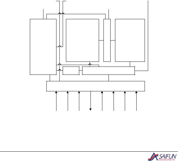
Memory Organization |
Each page can be individually |
|
programmed, with the bits programmed |
|
|
The memory is organized in the following |
from 1 to 0. The SA25F005's memory |
|
can be erased via the Page, Sector or |
|
|
manner: |
|
|
Bulk Erase commands, with the bits |
|
|
• 65,596 bytes (8 bits each) |
|
|
erased from 0 to 1. |
|
• 2 sectors (256 Kb total, 32,768 bytes each), as shown in Table 1
• 256 pages (256 bytes each)
Table 1. Memory Organization
Sector |
Address Range |
|
|
|
|
1 |
8000h |
0FFFFh |
|
|
|
0 |
00000h |
07FFFh |
|
|
|
SRAM |
|
PS |
|
|
|
||
|
|
|
|
|
X |
|
|
Array - L |
D |
Array - R |
|
E |
|||
|
|
||
Logic |
C |
|
|
|
RD |
|
DATA PATH |
|
|
|
|
|
|
|
IO |
|
|
|
CSb |
SCK |
SI |
SO |
GND |
Vcc |
WPb |
HOLDb |
Figure 1. SA25F005 Block Diagram
SA25F005 Advanced Information
SAIFUN 6
Connection Diagrams
CSb |
|
1 |
8 |
|
VCC |
|
|
||||
|
|
|
7 |
|
HOLDb |
SO |
|
2 |
|
||
|
|
|
SA25F005 |
|
SCK |
WPb |
|
3 |
6 |
|
|
|
|
|
5 |
|
SI |
GND |
|
4 |
|
||
|
|
|
|
|
|
Figure 2. SOIC 8 (150 mil)/PDIP/MLF Package (Top View)
|
Table 2. Pin Names |
|
|
|
|
Pin Name |
|
Signal Name |
|
|
|
CSb |
|
Chip Select |
SCK |
|
Serial Data Clock |
SI |
|
Serial Data Input |
SO |
|
Serial Data Output |
GND |
|
Ground |
|
|
|
VCC |
|
Power Supply |
WPb |
|
Write Protect |
|
|
|
HOLDb |
|
Suspend Serial Input |
|
|
|

SA25F005 Advanced Information
SAIFUN 7
Ordering Information
SA |
25 |
F |
XX |
L |
E |
PP |
F |
X |
Letter |
Description |
||||||||||||
|
|
|
|
|
|
|
|
|
|
|
|
|
|
|
|
|
|
|
|
|
Blank |
Tube |
|
|
|
|
|
|
|
|
|
|
|
|
|
|
|
|
|
|
|
|
|
X |
Tape and Reel |
|
|
|
|
|
|
|
|
|
|
|
|
|
|
|
|
|
|
|
|
|
Blank |
Non-lead Free |
|
|
|
|
|
|
|
|
|
|
|
|
|
|
|
|
|
|
|
|
|
F |
Lead Free |
|
|
|
|
|
|
|
|
|
|
|
|
|
|
|
|
|
Package |
N |
8-pin DIP |
|||
|
|
|
|
|
|
|
|
|
|
|
|
|
|
|
|
|
|
|
|
|
M8 |
8-pin SOIC (150 mil) |
|
|
|
|
|
|
|
|
|
|
|
|
|
|
|
|
|
|
|
|
|
||
|
|
|
|
|
|
|
|
|
|
|
|
|
|
|
|
|
|
|
|
|
MLF |
8-lead MLF |
|
|
|
|
|
|
|
|
|
|
|
|
|
|
|
|
Temp. Range |
Blank |
0 to 70oC |
||||
|
|
|
|
|
|
|
|
|
|
|
|
Voltage Operating Range |
|
E |
-40 to +85oC |
|||||||
|
|
|
|
|
|
|
|
|
|
|
|
|
L |
2.7 V to 3.6 V |
||||||||
|
|
|
|
|
|
|
|
|
|
|
|
|
|
|
|
|
||||||
|
|
|
|
|
|
|
|
|
|
|
|
|
|
|
|
|
|
Density |
005 |
512 Kb with Write |
||
|
|
|
|
|
|
|
|
|
|
|
|
|
|
|
|
|
|
Protect |
||||
|
|
|
|
|
|
|
|
|
|
|
|
|
|
|
|
|
|
|
|
|
|
|
|
|
|
|
|
|
|
|
|
|
|
|
|
|
|
|
|
|
|
|
|
F |
Flash |
|
|
|
|
|
|
|
|
|
|
|
|
|
|
|
|
|
Interface |
|||||
|
|
|
|
|
|
|
|
|
|
|
|
|
|
|
|
|
25 |
SPI-2 Wires |
||||
|
|
|
|
|
|
|
|
|
|
|
|
|
|
|
|
|
||||||
|
|
|
|
|
|
|
|
|
|
|
|
|
|
|
|
|
|
|
|
|
SA |
Saifun Non-Volatile |
|
|
|
|
|
|
|
|
|
|
|
|
|
|
|
|
|
|
|
|
|
Memory |
|
|
|
|
|
|
|
|
|
|
|
|
|
|
|
|
|
|
|
|
|
|
|
|
Figure 3. SA25F005 Ordering Information

SA25F005 Advanced Information
SAIFUN 8
Product Specifications
Absolute Maximum Ratings
Storage Temperature
All input or output voltages with respect to Ground
Lead Temperature (Soldering, 10 seconds)
ESD Rating
-65 ° C to +150 ° C 4.5 V to -0.3 V
+235 ° C
2000 V min.
ESD/Latch Up Specification (JEDEC 8 Spec)
Human Body Model |
Minimum 4 KV |
Machine Model |
Minimum 500 V |
Charge Device Model |
Minimum 1 KV |
Latch Up |
100 mA on all pins +125° C |
Operating Conditions
Operating Temperature: |
0 ° C to +70 ° C |
SA25F005 |
|
SA25F005E |
-40 ° C to +85 ° C |
Positive Power Supply: |
|
SA25F005 |
2.7 V to 3.6 V |

SA25F005 Advanced Information
SAIFUN 9
DC Characteristics
Applicable over recommended operating range from TAI = -40 ºC to 85 ºC, VCC = 2.7-3.6 V.
Table 3. DC Characteristics
Symbol |
Parameter |
Test Conditions |
|
Limits |
|
Unit |
|
|
|
||||||
Min |
Typ* |
Max |
|||||
|
|
|
|
||||
|
|
|
|
|
|
|
|
VCC |
Supply Voltage |
|
2.7 |
3 |
3.6 |
V |
|
|
|
|
|
|
|
|
|
ICC1 |
Active Power Supply |
SCK = 0.1VCC/0.9 VCC @ |
|
9 |
12 |
mA |
|
Current (Read) |
25 MHz |
|
|||||
|
|
|
|
|
|||
|
|
|
|
|
|
|
|
ICC2 |
Active Power Supply |
CSb = VCC |
|
|
15 |
mA |
|
Current (Page Program) |
|
|
|||||
|
|
|
|
|
|
||
|
|
|
|
|
|
|
|
ICC3 |
Active Power Supply |
CSb = VCC |
|
|
15 |
mA |
|
Current (WRSR) |
|
|
|||||
|
|
|
|
|
|
||
|
|
|
|
|
|
|
|
ICC4 |
Active Power Supply |
CSb = VCC |
|
|
15 |
mA |
|
Current (SE) |
|
|
|||||
|
|
|
|
|
|
||
|
|
|
|
|
|
|
|
ICC5 |
Active Power Supply |
CSb = VCC |
|
|
15 |
mA |
|
Current (BE) |
|
|
|||||
|
|
|
|
|
|
||
|
|
|
|
|
|
|
|
ISB |
Standby Current |
VCC = 3.0 V, |
|
|
1 |
A |
|
CSb = VCC |
|
|
|||||
|
|
|
|
|
|
||
|
|
|
|
|
|
|
|
IIL |
Input Leakage Current |
VIN = GND to VCC |
|
|
1 |
A |
|
|
|
|
|
|
|
|
|
IOL |
Output Leakage Current |
VIN = GND to VCC |
|
|
1 |
A |
|
|
|
|
|
|
|
|
|
VIL |
Input Low Voltage |
|
-0.3 |
|
0.3 VCC |
V |
|
|
|
|
|
|
|
|
|
VIH |
Input High Voltage |
|
0.7 VCC |
|
VCC + |
V |
|
|
|
0.5 |
|||||
|
|
|
|
|
|
||
|
|
|
|
|
|
|
|
VOH |
Output High Voltage |
IOH = -0.1 mA |
VCC - |
|
|
V |
|
0.2 |
|
|
|||||
|
|
|
|
|
|
||
|
|
|
|
|
|
|
|
VOL |
Output Low Voltage |
IOL = 1.6 mA; VCC = 2.7 V |
|
|
0.4 |
V |
|
|
|
|
|
|
|
|
*Typical values are at TAI = 25 ºC and 3 V.

SA25F005 Advanced Information |
10 |
SAIFUN |
AC Test Conditions
Table 4. AC Test Conditions
Symbol |
Parameter |
|
25 MHz |
|
Unit |
|
Min |
Typ |
Max |
||||
|
|
|
||||
|
|
|
|
|
|
|
FSCK |
SCK Clock Frequency |
D.C. |
|
25 |
MHz |
|
|
|
|
|
|
|
|
tCRT |
Clock Rise Time (Slew Rate) |
0.1 |
|
|
V/ns |
|
|
|
|
|
|
|
|
tCFT |
Clock Fall Time (Slew Rate) |
0.1 |
|
|
V/ns |
|
|
|
|
|
|
|
|
tWH |
SCK High Time |
18 |
|
|
ns |
|
|
|
|
|
|
|
|
tWL |
SCK Low Time |
18 |
|
|
ns |
|
|
|
|
|
|
|
|
tCS |
CSb High Time |
100 |
|
|
ns |
|
|
|
|
|
|
|
|
** |
CSb Setup Time |
10 |
|
|
ns |
|
tCSS |
|
|
||||
** |
CSb HOLD Time |
10 |
|
|
ns |
|
tCSH |
|
|
||||
** |
HOLDb Setup Time |
10 |
|
|
ns |
|
tHD |
|
|
||||
** |
HOLDb Hold Time |
10 |
|
|
ns |
|
tCD |
|
|
||||
tV |
Output Valid |
0 |
|
15 |
ns |
|
|
|
|
|
|
|
|
tHO |
Output Hold Time |
0 |
|
|
ns |
|
|
|
|
|
|
|
|
tHD:DAT |
Data in Hold Time |
5 |
|
|
ns |
|
|
|
|
|
|
|
|
tSU:DAT |
Data in Setup Time |
5 |
|
|
ns |
|
tLZ ** |
HOLDb to Output Low Z |
|
|
15 |
ns |
|
tHZ ** |
HOLDb to Output High Z |
|
|
20 |
ns |
|
** |
Output Disable Time |
|
|
15 |
ns |
|
tDIS |
|
|
||||
** |
Write Protect Setup Time |
20 |
|
|
ns |
|
tWPS |
|
|
||||
** |
Write Protect Hold Time |
100 |
|
|
ns |
|
tWPH |
|
|
||||
tPP* |
256-byte Page Programming |
|
8 |
10 |
ms |
|
|
|
|
|
|
|
|
tEP* |
Page Erase and |
|
10 |
15 |
ms |
|
Programming |
|
|||||
|
|
|
|
|
||
tPE |
Page Erase Time |
|
3 |
6 |
ms |
|
|
|
|
|
|
|
|
tSE |
Sector Erase Time |
|
0.3 |
0.4 |
sec |
|
tBE |
Bulk Erase Time |
|
0.5 |
0.8 |
sec |
|
tRES |
Release SP Mode |
|
|
1000 |
ns |
|
Endurance |
|
100K |
|
|
Erase cycles |
|
|
|
|
|
|
|
*256 bytes in the checkerboard programming formation.
**Value guaranteed by characterization, not 100% tested in production

SA25F005 Advanced Information
SAIFUN 11
Timing Diagrams
All timing diagrams are based on SPI protocol modes 0 and 1.
tCS
CS |
|
|
|
|
|
|
tCSH |
t |
CSS |
|
t |
CSH |
t |
|
|
|
|
CSS |
||
SCK |
|
|
|
|
|
|
|
tSU:DAT tHD:DAT |
tCRT |
tCFT |
|
|
|
|
|
|
|
|
|
|
SI |
MSB IN |
|
|
LSB IN |
|
|
High Impedance
SO
Figure 4. SPI Mode 0 (0,0) Input Timing
CS |
|
|
|
|
|
tWH |
|
SCK |
|
|
|
tV |
tV |
tWL |
tDIS |
tHO |
tHO |
||
|
|
||
SO |
|
|
LSB OUT |
Figure 5. SPI Mode 0 (0,0) Output Timing

SA25F005 Advanced Information
SAIFUN 12
Input Levels |
|
Input and Output |
|||
Timing Reference Levels |
|||||
|
|
||||
0.8Vcc |
|
|
|
0.7Vcc |
|
|
|
|
|
||
0.2Vcc |
|
|
|
0.3Vcc |
|
|
|
|
|
||
|
Figure 6. AC Measurements I/O Waveform |
|
|||
|
Table 5. AC Measurements |
|
|||
Symbol |
Parameter |
Min |
Max |
Unit |
|
CL |
Load Capacitance |
|
30 |
pF |
|
|
Input Rise and Fall Times |
|
5 |
ns |
|
|
Input Pulse Voltage |
0.2 VCC to 0.8 VCC |
V |
||
|
Input and Output Timing |
0.3 VCC to 0.7 VCC |
V |
||
|
Reference Voltages |
||||
|
|
|
|
||
 Loading...