

Page 1

Reference Manual
F@ST 4310
Page 2

Page 3
Sagemcom assiduously monitors technical developments and is constantly seeking to improve its products in
order to let its clients take full advantage of them. It therefore reserves the right to modify its documentation
accordingly without notice.
All brands mentioned in this guide are registered by their respective owners:
• F@ST is a registered trademark.
• Sagemcom is a registered trademark.
• Windows
The purpose of this reference manual is to give users the functions for operating and managing the equipment.
The only access level required (Administrator) is protected by a password and allows one to access these
functions in read and write mode for all the user and network parameters (Login: admin; password: xxxx).
Note
To ease legibility of the reference manual, the term "router" will be used throughout the document to designate
F@ST 4310 equipment.
TM
and Internet ExplorerTM are registered trademarks of Microsoft Corporation.
Configuration of the router by HTTP is described in detail (cf. section 5).
Guide to symbols used in this manual
Symbols Definition
Note
Important
Gives you important information which you must take into account.
Warns you not to do an action, or commit a serious omission.
F@ST 4310 Reference Manual Page 0-1
Sagemcom Broadband SAS document. Reproduction and disclosure prohibited
Page 4

How should the document be used?
This reference manual is organised into sections and annexes. These sections and annexes cover the
following subjects.
Section 1 Presentation of F@ST 4310 equipment
Section 2 Description of F@ST 4310 equipment
Section 3 Installation of F@ST 4310 equipment
Section 4 Configuration of network parameters
Section 5 Configuration of the router by HTTP
Section 6 Configuration of the advanced parameters
Section 6 Description of Internet access service
Section 7 Description of TV over ADSL service
Section 8 Updating the application
Annex A Troubleshooting
Annex B EC compliance declaration
Annex C Environment
Annex D Technical Characteristics
Annex E Default configuration
Annex F Glossary
Annex G Connector technology
Page 0-2 F@ST 4310 Reference Manual
Sagemcom Broadband SAS document. Reproduction and disclosure prohibited
Page 5

Contents
Pages
Guide to symbols used in this manual .........................................................................................................0-1
How should the document be used? ............................................................................................................0-2
Contents........................................................................................................................................................... 0-3
1. Introduction ............................................................................................................................... 1-1
1.1 Presentation ..................................................................................................................................... 1-2
1.1.1 Connection ........................................................................................................................................... 1-2
1.1.2 Characteristic ....................................................................................................................................... 1-3
1.2 Composition of router pack .............................................................................................................. 1-4
1.3 (Minimum) prerequisites ................................................................................................................... 1-5
2. Description and connection of router ..................................................................................... 2-1
2.1 Description ....................................................................................................................................... 2-2
2.1.1 Connectors .......................................................................................................................................... 2-3
2.1.2 LEDs and buttons ................................................................................................................................ 2-4
2.2 Connecting the ports of your router .................................................................................................. 2-6
2.3 Installation of your F@ST 4310 ........................................................................................................ 2-7
2.3.1 Powering up ......................................................................................................................................... 2-7
2.3.2 Connecting the ADSL cable ................................................................................................................. 2-7
2.3.3 Connecting to your computer ............................................................................................................... 2-8
2.3.4 Connecting the Ethernet interface of your router to your TV decoder ................................................. 2-9
2.3.5 Connecting the USB interface of your router ....................................................................................... 2-9
2.4 Installation safety instructions ........................................................................................................ 2-10
3. Installing and configuring
the F@ST 4310 router3-1
4. Configuration of network parameters ..................................................................................... 4-1
4.1 Configuring as a DHCP client ........................................................................................................... 4-3
4.2 Status of the DHCP server ............................................................................................................... 4-4
4.3 Data of the DHCP client ................................................................................................................... 4-5
5. Information / Configuration...................................................................................................... 5-1
5.1 Accessing the welcome screen ........................................................................................................ 5-2
5.2 Recommendations ........................................................................................................................... 5-4
F@ST 4310 Reference Manual Page 0-3
Sagemcom Broadband SAS document. Reproduction and disclosure prohibited
Page 6

5.3 ADSL connection status ................................................................................................................... 5-5
5.4 Display frame ................................................................................................................................... 5-5
5.5 Device Info ....................................................................................................................................... 5-6
5.5.1 Summary ............................................................................................................................................. 5-6
5.5.2 WAN .................................................................................................................................................... 5-7
5.5.3 3G Status ............................................................................................................................................. 5-8
5.5.4 Statistics .............................................................................................................................................. 5-8
5.5.5 Route ................................................................................................................................................. 5-13
5.5.6 ARP ................................................................................................................................................... 5-14
5.5.7 DHCP ................................................................................................................................................. 5-15
5.6 Internet Connection ........................................................................................................................ 5-16
5.7 Advanced Setup ............................................................................................................................. 5-17
5.7.1 Layer2 Interface ................................................................................................................................. 5-18
5.7.2 WAN Service ..................................................................................................................................... 5-23
5.7.3 3G Config ........................................................................................................................................... 5-47
5.7.4 LAN .................................................................................................................................................... 5-48
5.7.5 NAT .................................................................................................................................................... 5-50
5.7.6 Security .............................................................................................................................................. 5-57
5.7.7 Parental Control ................................................................................................................................. 5-61
5.7.8 Quality of Service ............................................................................................................................... 5-64
5.7.9 Routing .............................................................................................................................................. 5-72
5.7.10 DNS ................................................................................................................................................... 5-75
5.7.11 DSL .................................................................................................................................................... 5-78
5.7.12 Upnp .................................................................................................................................................. 5-81
5.7.13 DNS Proxy ......................................................................................................................................... 5-82
5.7.14 Interface Grouping ............................................................................................................................. 5-83
5.7.15 Certificate ........................................................................................................................................... 5-86
5.7.16 Power Management ........................................................................................................................... 5-90
5.7.17 Multicast ............................................................................................................................................. 5-91
5.8 Wireless .......................................................................................................................................... 5-93
5.8.1 Basic .................................................................................................................................................. 5-93
5.8.2 Security .............................................................................................................................................. 5-96
5.8.3 MAC Filter ........................................................................................................................................ 5-108
5.8.4 Wireless Bridge ................................................................................................................................ 5-110
5.8.5 Advanced ......................................................................................................................................... 5-111
5.8.6 Station Info ....................................................................................................................................... 5-115
5.9 Multimedia .................................................................................................................................... 5-116
5.9.1 Print Server ...................................................................................................................................... 5-116
5.9.2 Storage Service ............................................................................................................................... 5-116
5.10Diagnostics .................................................................................................................................. 5-119
5.11Management ................................................................................................................................ 5-120
5.11.1 Settings ............................................................................................................................................ 5-120
Page 0-4 F@ST 4310 Reference Manual
Sagemcom Broadband SAS document. Reproduction and disclosure prohibited
Page 7

5.11.2 System Log ...................................................................................................................................... 5-125
5.11.3 Security Log ..................................................................................................................................... 5-128
5.11.4 TR-069 Client ................................................................................................................................... 5-129
5.11.5 Internet Time .................................................................................................................................... 5-130
5.11.6 Access Control ................................................................................................................................. 5-131
5.11.7 Update Software .............................................................................................................................. 5-132
5.11.8 Reboot ............................................................................................................................................. 5-133
6. Internet access service............................................................................................................. 6-1
7. TV over ADSL service............................................................................................................... 7-1
7.1 Introduction ....................................................................................................................................... 7-2
7.2 Access to the optional TV over ADSL service .................................................................................. 7-2
8. Updating the firmware .............................................................................................................. 8-1
Annex A - Troubleshooting.............................................................................................................A-1
A.1 Checking the assignment of an IP address ...................................................................................... A-2
A.2 Front panel LEDs ............................................................................................................................. A-3
A.3 Supervising your router .................................................................................................................... A-4
A.4 Diagnostics tool ................................................................................................................................ A-5
A.5 Interpreting the LEDs ....................................................................................................................... A-6
A.5.1 The "ADSL" LED blinks slowly ............................................................................................................. A-6
A.5.2 "Wi-Fi" LED off ..................................................................................................................................... A-6
A.5.3 All LEDs are off .................................................................................................................................... A-6
A.6 Restarting your router ....................................................................................................................... A-7
A.7 Resetting factory configuration ......................................................................................................... A-7
A.8 Offline mode ..................................................................................................................................... A-8
Annex B - Warnings for safety........................................................................................................B-1
B.1 Warnings for safety .......................................................................................................................... B-2
B.1.1 Safety levels in relation to the case ..................................................................................................... B-2
B.2 EC compliance declaration ............................................................................................................... B-2
Annex C - Environment ...................................................................................................................C-1
C.1 Directive E 2002/96/CE ................................................................................................................... C-2
Annex D - Technical Characteristics..............................................................................................D-1
D.1 Mechanics; Display ......................................................................................................................... D-2
D.2 Characteristics of the different interfaces ........................................................................................ D-3
D.3 Environmental characteristics ......................................................................................................... D-5
D.4 Application and protocols ................................................................................................................ D-6
Annex E - Default configuration .....................................................................................................E-1
E.1 Default username and password ...................................................................................................... E-2
F@ST 4310 Reference Manual Page 0-5
Sagemcom Broadband SAS document. Reproduction and disclosure prohibited
Page 8

E.2 Default configuration for the local network(LAN) .............................................................................. E-2
E.3 Default configuration for the local wireless network (WLAN) ........................................................... E-2
Annex F - Glossary .......................................................................................................................... F-1
Annex G - Connector Technology..................................................................................................G-1
G.1 Pinouts of the LINE connector ......................................................................................................... G-2
G.2 Pinouts of the PWR connector ........................................................................................................ G-3
G.3 Pinouts of the LAN1, LAN2, LAN3 and LAN4 connectors ............................................................... G-4
Page 0-6 F@ST 4310 Reference Manual
Sagemcom Broadband SAS document. Reproduction and disclosure prohibited
Page 9

1. Introduction
This section covers • presentation of the F@ST 4310 router § 1.1
• composition of the packaging § 1.2
• required hardware and software § 1.3
F@ST 4310 Reference Manual Page 1-1
Sagemcom Broadband SAS document. Reproduction and disclosure prohibited
Page 10
1- Introduction
1WAN
+
-
RESET
2
34DSL
RJ11
RJ11
RJ45
RJ45
PHONE
Filter/Spitter
LINE
MODEM
Line
wall socket
PWR
Phone set
Mains Adapter
with its lead
Mains
wall socket
OR
Not included
1.1 Presentation
This reference manual is dedicated to the F@ST 4310 equipment. This equipment is a router which gives
users broadband Internet access from their computer or their game console by various Ethernet (10 or 100
BASE-T) or Wi-Fi (IEEE 802.11n) interfaces via an ADSL/ADSL2/ ADSL2+ network.
Using these interfaces, this router enables you both to surf the Internet and to watch television. It also allows
give phone calls over the Internet from an IP SIP telephone linked by Wi-Fi to your router.
Important
F@ST 4310 products adapt the ADSL function respectively for POTS (UIT
G.992.1/3/5 - Annex A) and for ISDN (UIT G.992.1/3/5 - Annex B).
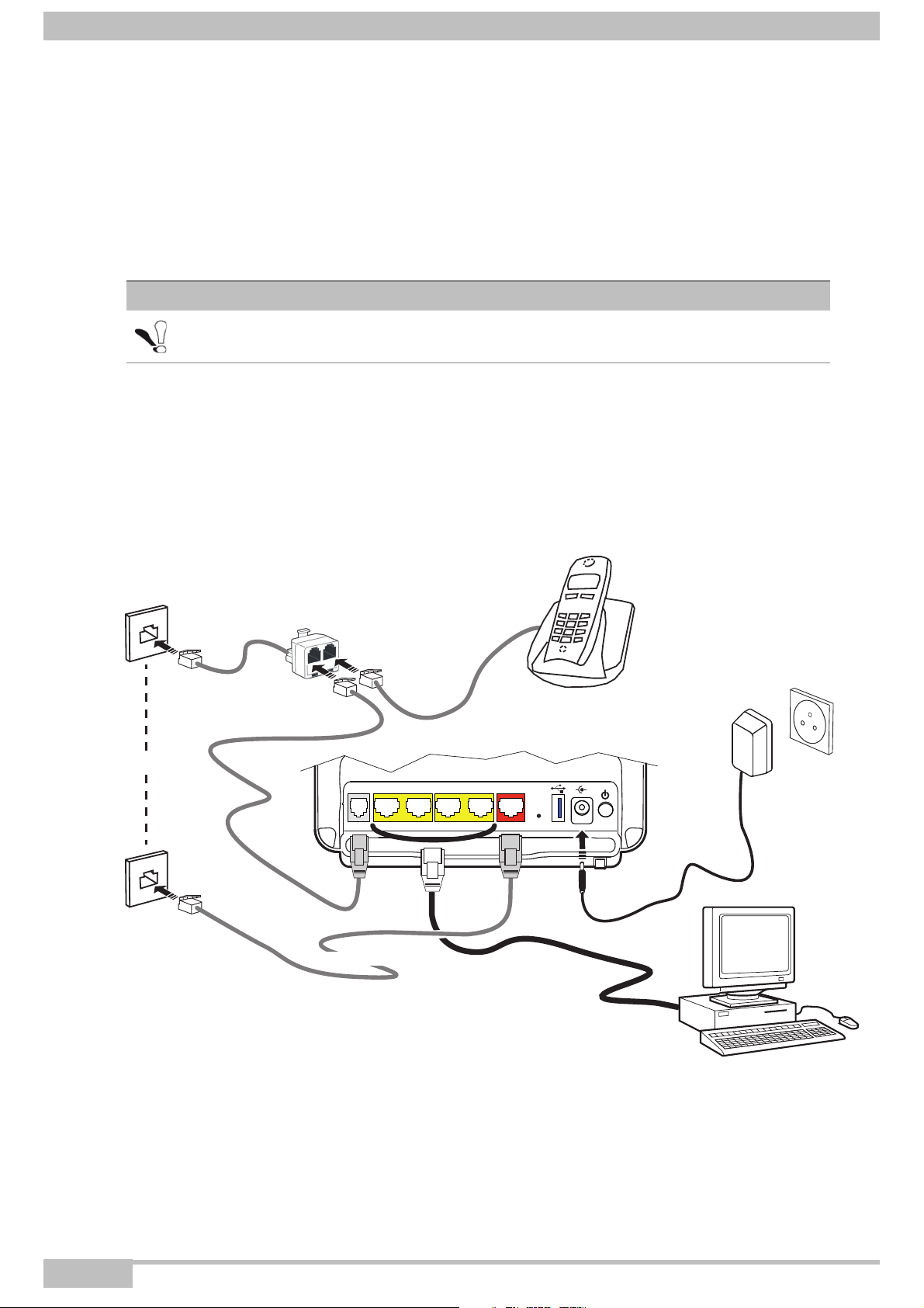
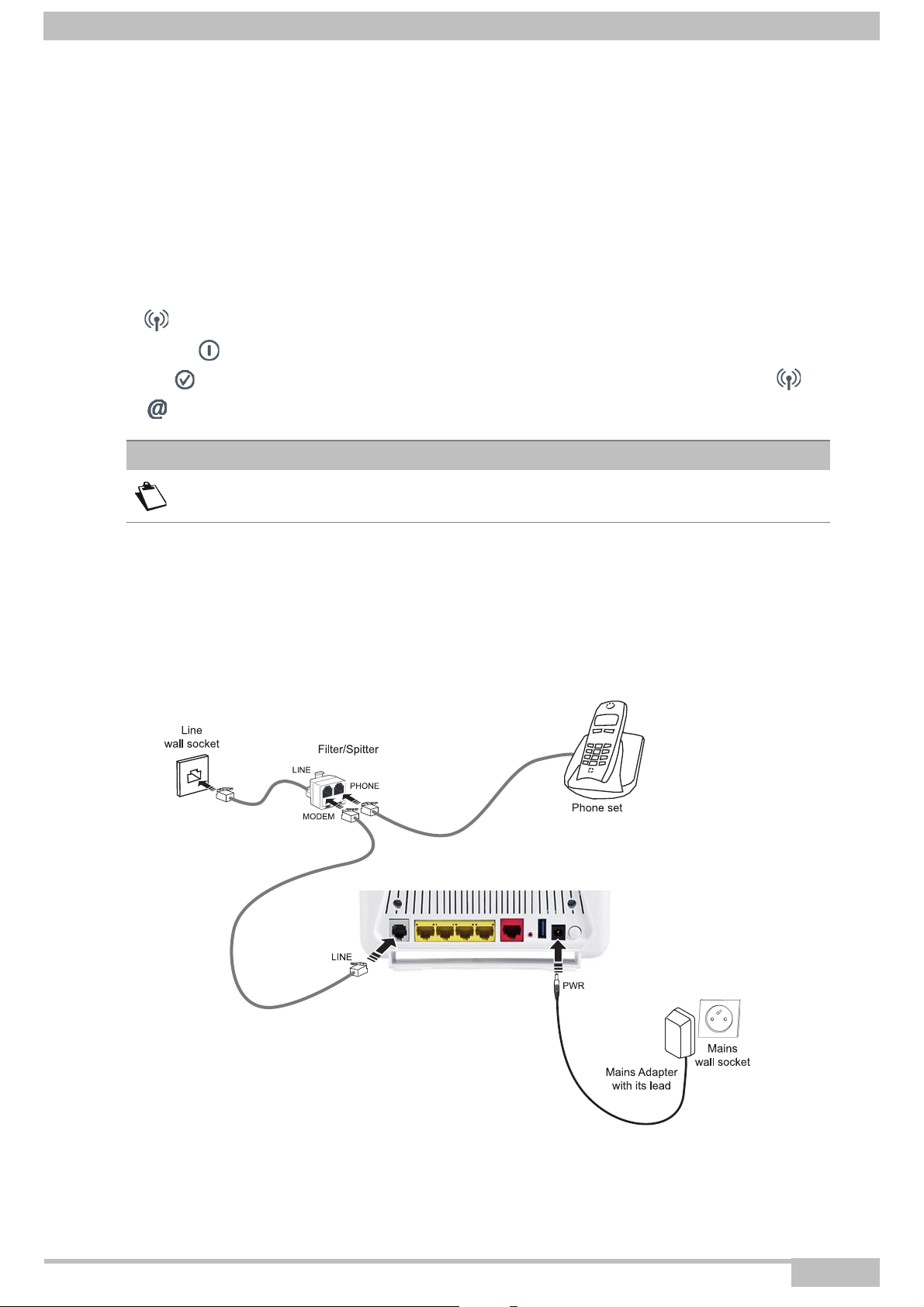
1.1.1 Connection
Connecting your router
Make the connections as shown in the diagram below.
Page 1-2 F@ST 4310 Reference Manual
Sagemcom Broadband SAS document. Reproduction and disclosure prohibited
Page 11

1- Introduction
1.1.2 Characteristic
Its principal characteristics and functions are as follows:
• High-performance secure Bridge/Router with ADSL/ADSL2/ADSL2+ and Fast Ethernet (for FTTH)
interfaces,
• User access:
- 4 x 10/100BT Ethernet ports,
- 1 Wi-Fi interface (802.11n),
- 2 USB 2.0.,
- HSDPA backup,
- Samba server,
- DLNA server v 1.5.
• DHCP Client/Server/Relay,
• DNS Server/Relay,
• Access control (FTP/TELNET/HTTP/SSH Client),
• NAT/PAT router - FTP Compatibility, IRC, Net2Phone, Netbios, DNS, Netmeeting, VPN passthrough
(IPSec, IKE, PPTP, L2TP), CUSeeMe, RealAudio, Microsoft IM and others,
• Security,
• Firewall,
• Spanning tree,
• Multi-VC ATM and ATM Quality of service (CBR, UBR, VBR),
• UPnP,
• TR069,
• QoS,
• Upgrade Firmware (Local and Remote),
• Backup/Restore and Upgrade configuration file (Local and Remote).
F@ST 4310 Reference Manual Page 1-3
Sagemcom Broadband SAS document. Reproduction and disclosure prohibited
Page 12
1- Introduction
5
4
32
1
7
6
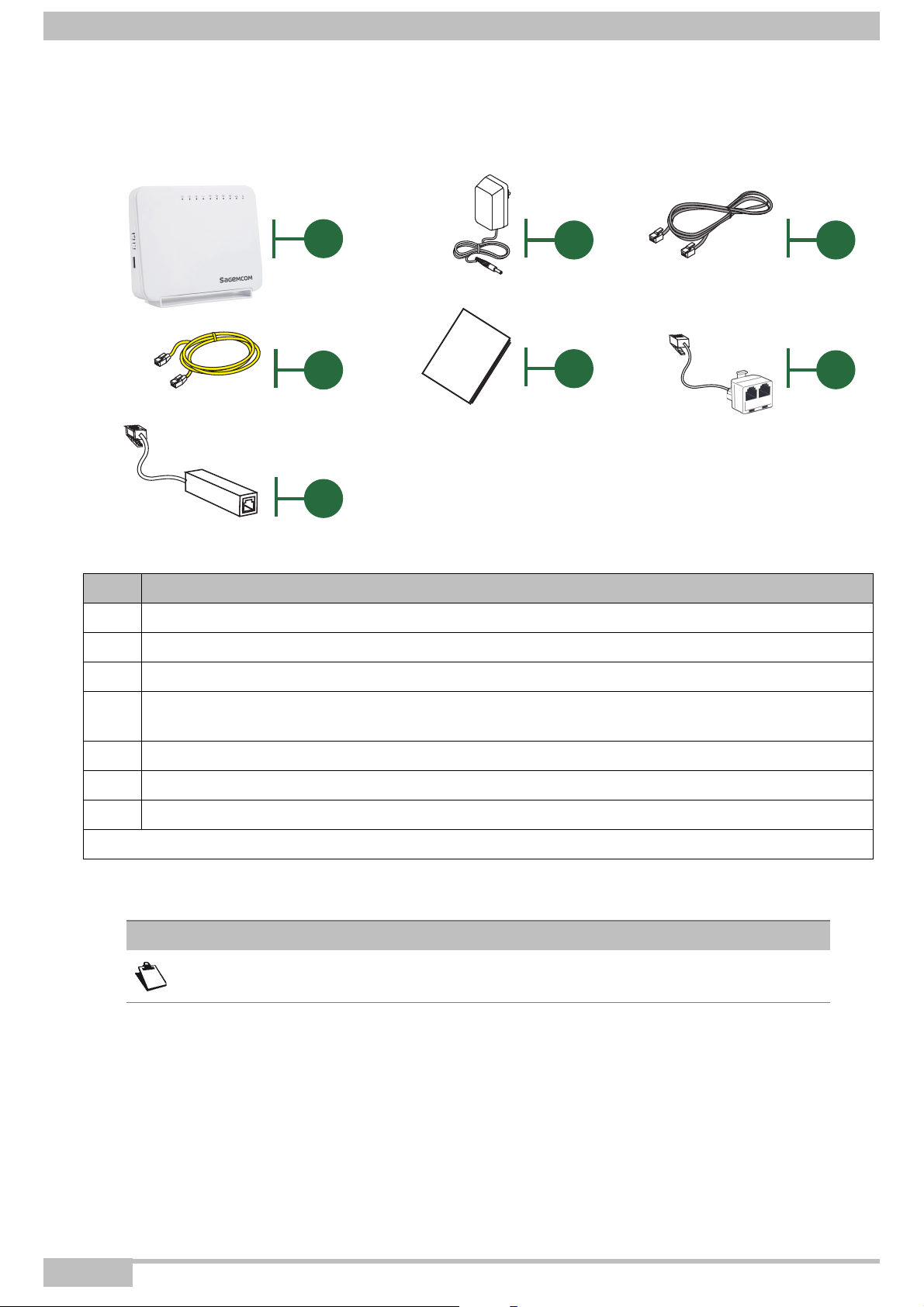
1.2 Composition of router pack
The router pack is composed of the following elements (present content may vary):
Item Description
1 F@ST 4310 router
2 Mains adapter
3 ADSL RJ11/11 FDT line cable (length = 3 m) used to connect your router to your telephone line
Ethernet RJ45/RJ45 cable (length = 1.75 m) used to connect your router to the Ethernet port of
4
your computer
5 Quick Installation Guide
6 Filter/Splitter used to connect one phone set and your router to your telephone line*
7 Microfilter used to connect another phone set to your telephone line*
* Option depending on pack content requested
Note
Incomplete or damaged supply
If on its receipt the equipment is damaged or incomplete, contact your supplier.
Page 1-4 F@ST 4310 Reference Manual
Sagemcom Broadband SAS document. Reproduction and disclosure prohibited
Page 13

1- Introduction
1.3 (Minimum) prerequisites
Using a router requires a minimum of:
• a computer equipped with:
- a Wi-Fi 802.11n interface,
or
- an Ethernet interface (10/100BASE-T).
• a WEB browser (Internet Explorer version 8 or higher recommended, Google Chrome, Firefox, Safari).
The minimum configuration of your computer must be:
• for Windows: Pentium IV, 2,8 GHz, RAM: 1Go,
• for MacOS: Power PC G5, 2,5GHz, RAM: 1Go,
• a monitor of minimum resolution: 1024 x 768.
If you wish to use the Wi-Fi function (standard IEEE 802.11n), you must have the Wi-Fi Standard pack (see
Annex G for use of Wi-Fi).
Note
Before installing the router, we advise you to uninstall any modem or other router
(for example, an ADSL router).
F@ST 4310 Reference Manual Page 1-5
Sagemcom Broadband SAS document. Reproduction and disclosure prohibited
Page 14

1- Introduction
Page 1-6 F@ST 4310 Reference Manual
Sagemcom Broadband SAS document. Reproduction and disclosure prohibited
Page 15

2. Description and connection of router
This section covers • the description of your router § 2.1
• connecting the ports of your router § 2.2
• installing your router § 2.3
• installation safety instructions § 2.4
F@ST 4310 Reference Manual Page 2-1
Sagemcom Broadband SAS document. Reproduction and disclosure prohibited
Page 16
2- Description and connection of router
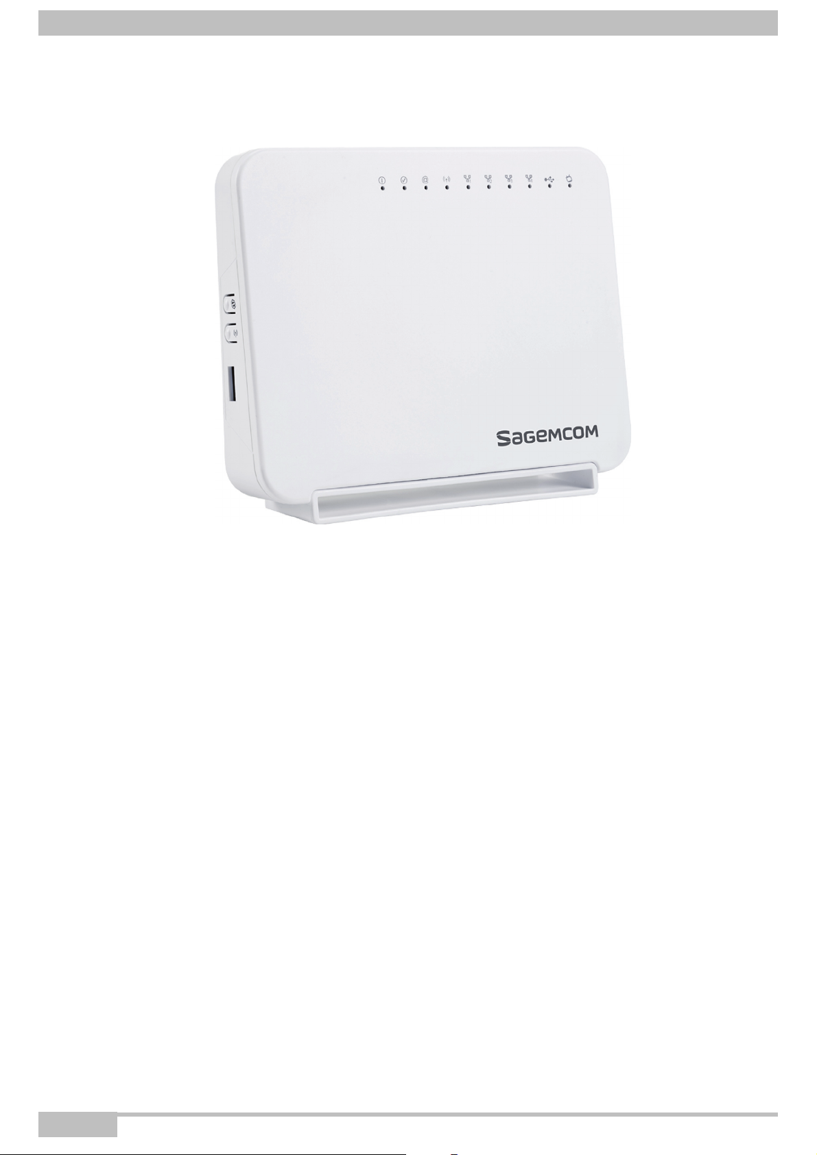
2.1 Description
The following figure gives an overview of a router F@ST 4310.
Figure 2.1 - Overview of case
This case consists principally of a lid and a base. Inside is a printed circuit equipped with electronic
components.
The front face of the lid has ten display LEDs (see § 2.1.2).
The base has the LED ideograms and the manufacturer logo.
Behind the base is a label on which the product's identification code, serial number and barcode are shown.
Page 2-2 F@ST 4310 Reference Manual
Sagemcom Broadband SAS document. Reproduction and disclosure prohibited
Page 17
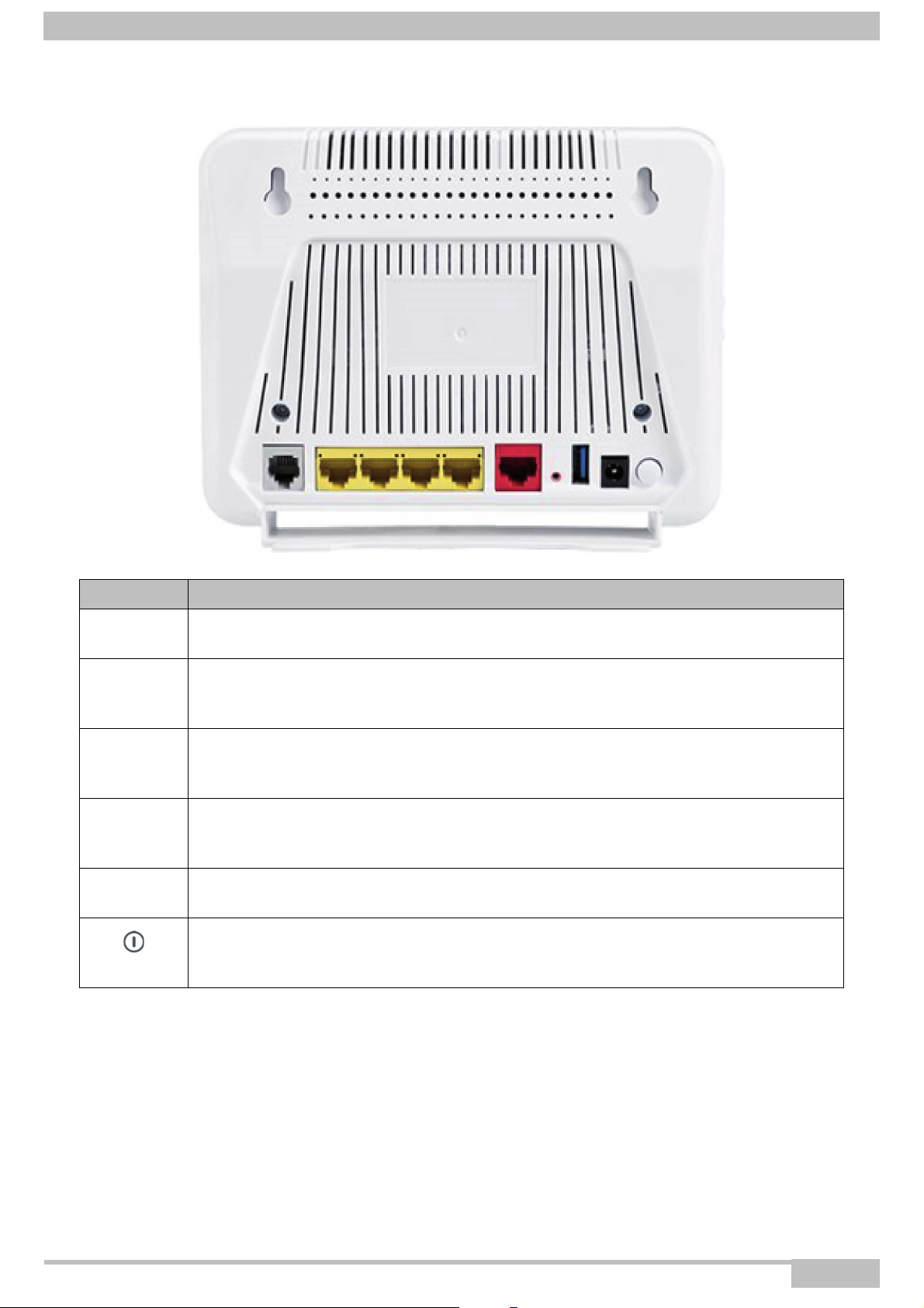
2.1.1 Connectors
2- Description and connection of router
Marking Meaning
LINE
LAN x
(1 to 4)
WAN
RESET
USB
Power
RJ11 connector - 6 pts. This connector is identified by the colour grey.
It is used for the connection to an ADSL line (WAN interface).
RJ45 connectors - 8 pts (10/100BASE-T Ethernet Interface). These connectors are
identified by the colour yellow.
They are used to connect to a computer or a television set (via a TV/Video Decoder).
RJ45 connector - 8 pts (10/100BASE-T Ethernet Interface). This connector is
identified by the color red.
FTTH dedicated port
This button allows the router to be reset to the factory configuration (see § A.7).
This operation deletes the entire personalised configuration of your router: Password,
Configuration, etc..
“Master” USB type A female connector (USB Interface ) used for “Memory sharing”
and “Printer sharing”
Miniature jack fixed connector.
This connector enables the router to be supplied with direct current from a mains
adapter unit.
F@ST 4310 Reference Manual Page 2-3
Sagemcom Broadband SAS document. Reproduction and disclosure prohibited
Page 18
2- Description and connection of router
2.1.2 LEDs and buttons
2.1.2.1 On the front panel
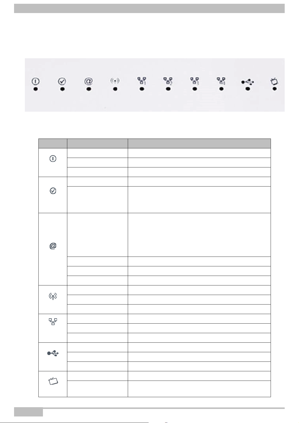
The following table describes the meaning of the LEDs on the front panel of the router:
LED Status Meaning
Off Power Off
Power
ADSL
Internet
WLAN
Green Power On
Red Router in rescue mode
Green steady ADSL Up
• ADSL Synchronisation in progress
Green blinking
Off
Green steady The Internet account is configured
Green blinking Tx/Rx traffic
Red Invalid or unauthorised Internet account
Off Wi-Fi deactivated
Green steady Wi-Fi activated
Green blinking Wi-Fi Tx/Rx
or
• down
• Power Off
or
• The Internet account must be configured
or
• Bridge mode
Off No link detected on the Ethernet port
LAN x
(1 to 4)
USB
TV
Page 2-4 F@ST 4310 Reference Manual
Green steady Ethernet port has detected a link with 100 Mbps device
Green blinking Tx/Rx traffic at 100 Mbps
Off No USB connection
Green steady USB connection available
Green blinking USB connection reading in progress
Green steady activated
Green blinking Playing IPTV
Sagemcom Broadband SAS document. Reproduction and disclosure prohibited
Page 19
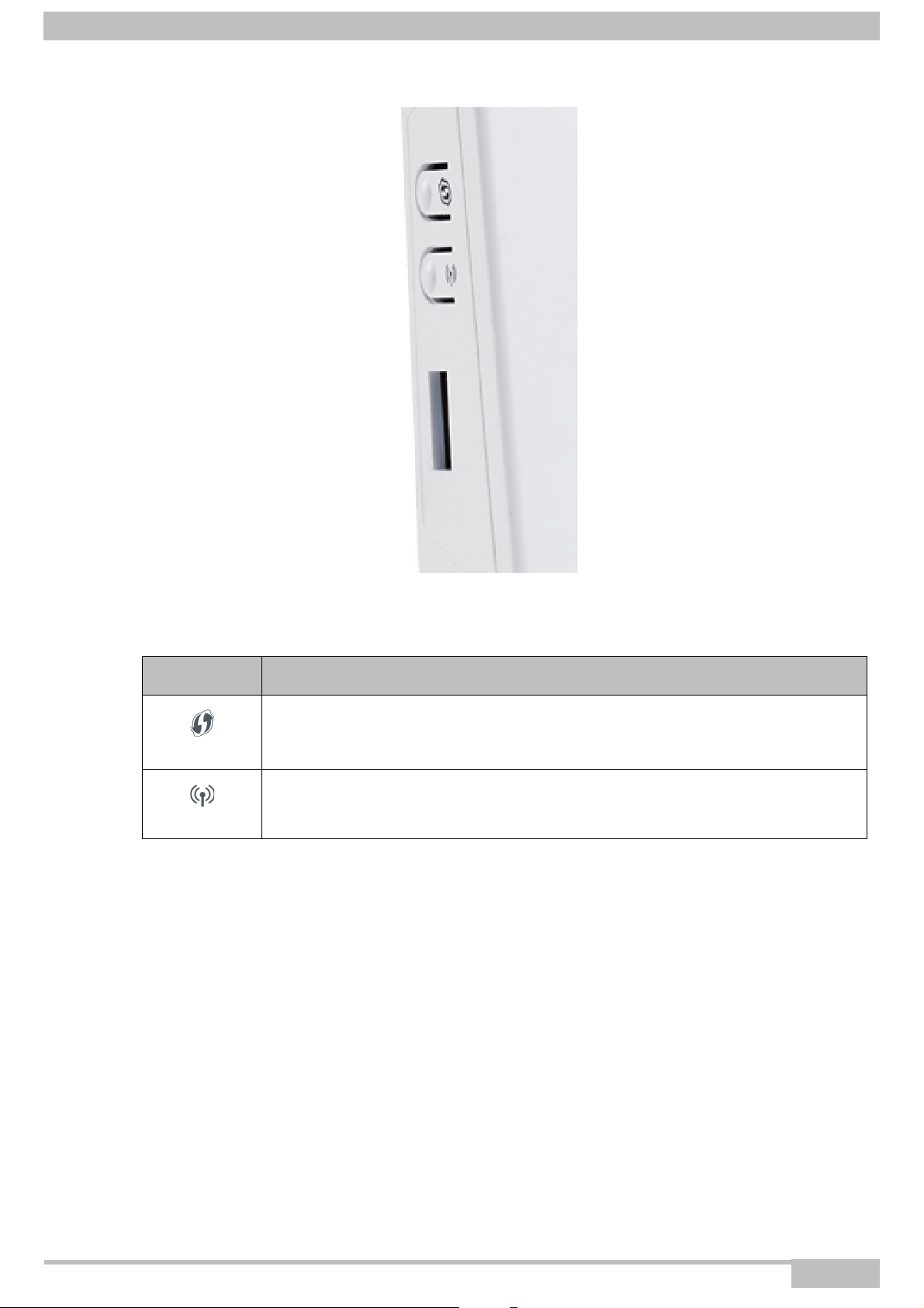
2.1.2.2 On the right panel
2- Description and connection of router
The following table describes the meaning of the buttons on the right panel of the router:
Button Action
This button allows the router to switch to easy-pairing mode.
WPS
This button allows to activate or deactivate the WiFi connection.
WLAN
F@ST 4310 Reference Manual Page 2-5
Sagemcom Broadband SAS document. Reproduction and disclosure prohibited
Page 20
2- Description and connection of router
Computers associated with the 802.11n Wi-Fi network
FTTH cable
USB Interface used to "Memory Sharing"
and "Printer sharing"
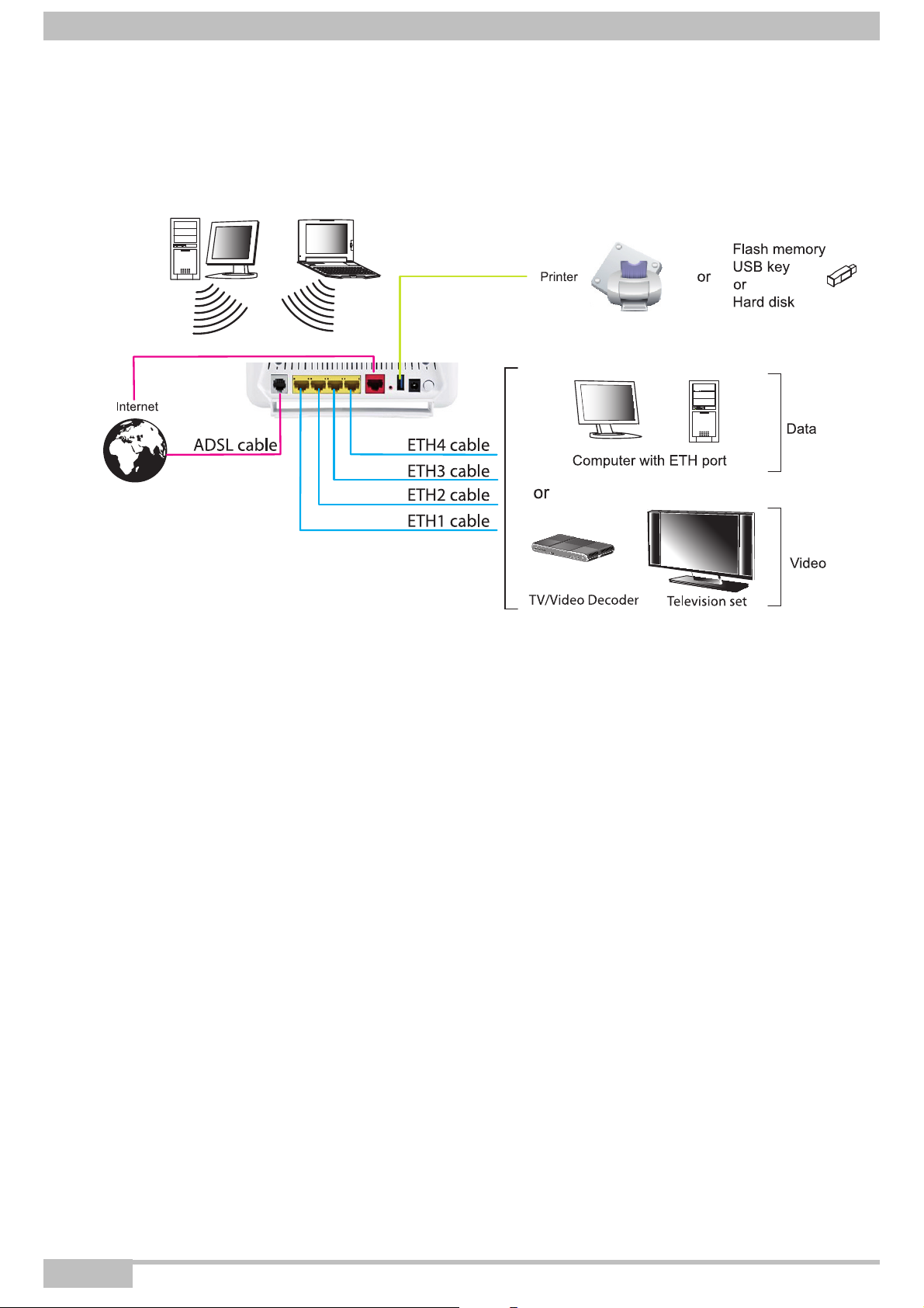
2.2 Connecting the ports of your router
Figure 2.2 - Interconnection of ports of F@ST 4310
Page 2-6 F@ST 4310 Reference Manual
Sagemcom Broadband SAS document. Reproduction and disclosure prohibited
Page 21
2- Description and connection of router
L
i
n
e
c
a
b
l
e
2.3 Installation of your F@ST 4310
2.3.1 Powering up
1. First connect the end of the mains adapter lead, supplied with the equipment, to the Power socket on
your router.
2. Connect the other end of the mains adapter lead to a nearby power outlet.
3. The router switches on automatically.
4. The LED will light up first, followed by the four Ethernet LEDs (1 to 4), then these last four LEDs will
be off. The and Ethernet (which corresponds to the connected interface) LEDs should be steady
and the LED blinks during the establishment of the ADSL link, then steadies like the LED.
The LED goes from blinking to steady when a PPP session has been created successfully.
Note
The powering up process lasts around one minute.
2.3.2 Connecting the ADSL cable
1. Connect one end of the RJ11/RJ11 cable supplied with the equipment to the LINE socket of your
router.
2. Connect the other end of the cable as shown in the following figure.
Figure 2.3 - ADSL line / Power Supply Connection
F@ST 4310 Reference Manual Page 2-7
Sagemcom Broadband SAS document. Reproduction and disclosure prohibited
Page 22
2- Description and connection of router
2.3.3 Connecting to your computer
Two kinds of connection can be made:
• Connection of the Ethernet interface of your router to your computer.
• Connection of the WLAN (Wi-Fi) interface to your computer.
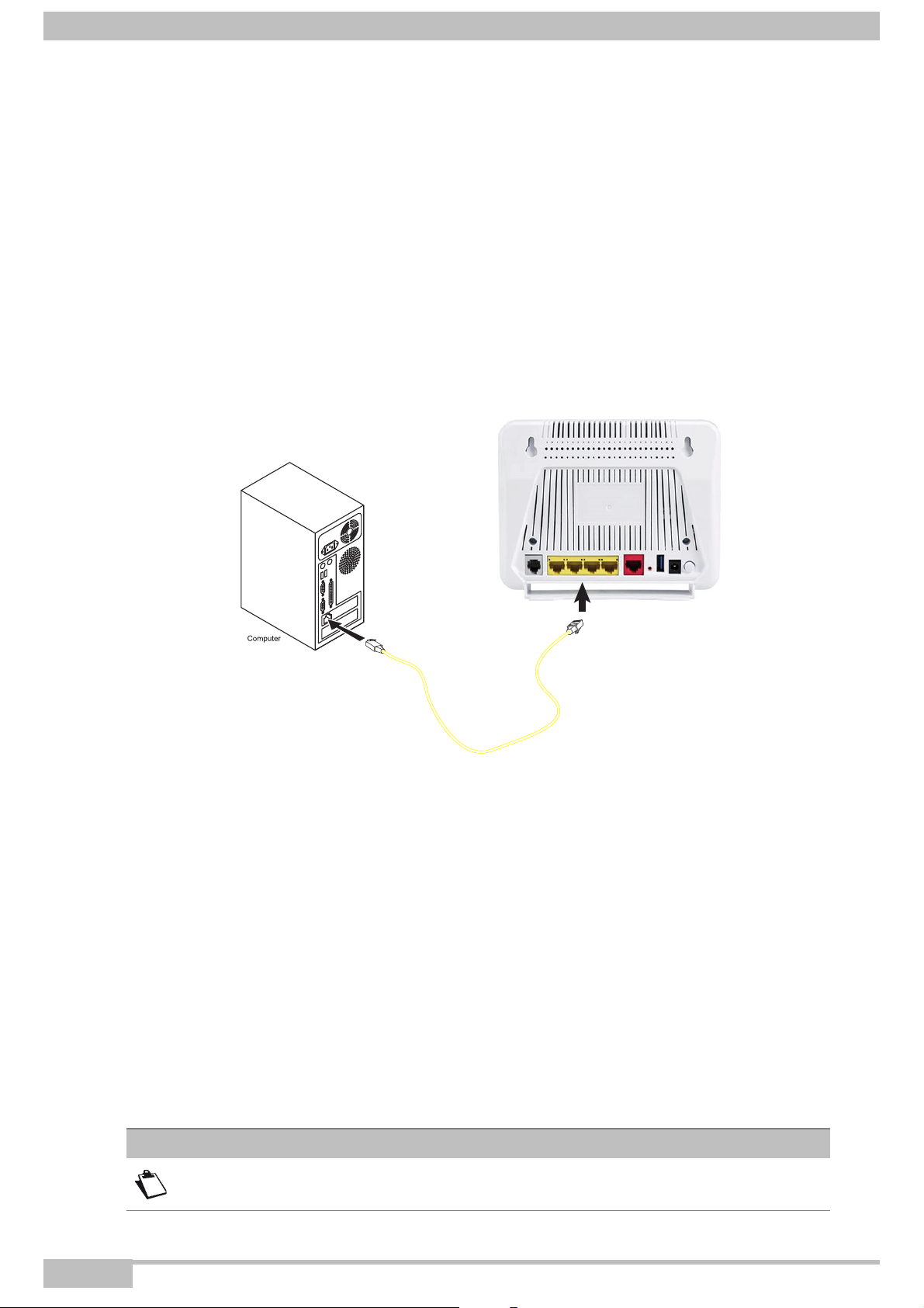
2.3.3.1 Connecting the Ethernet interface of your router to your computer
1. Connect the end of the yellow Ethernet cable (RJ45/RJ45) supplied in the pack to the Ethernet fixed
connector (marked LAN1, LAN2, LAN3 or LAN4) of your router.
2. Connect the other end of the cable to your computer.
2.3.3.2 Connecting the Wi-Fi interface of your router to your computer
Wireless linking enables the router to be connected to your computer.
To make this connection you must have a Wi-Fi pack (option). This pack comprises the following elements:
• Wi-Fi 188470912 key (Dongle) in an anti-static plastic bag,
• CD-ROM.
Inserting a USB Wi-Fi key in your computer
This key should only be connected to your computer during installation of the Wi-Fi drivers (standard
802.11n) (see Quick Installation Guide).
Note
You can also use the Wi-Fi adapter incorporated in your computer.
Page 2-8 F@ST 4310 Reference Manual
Sagemcom Broadband SAS document. Reproduction and disclosure prohibited
Page 23
2- Description and connection of router
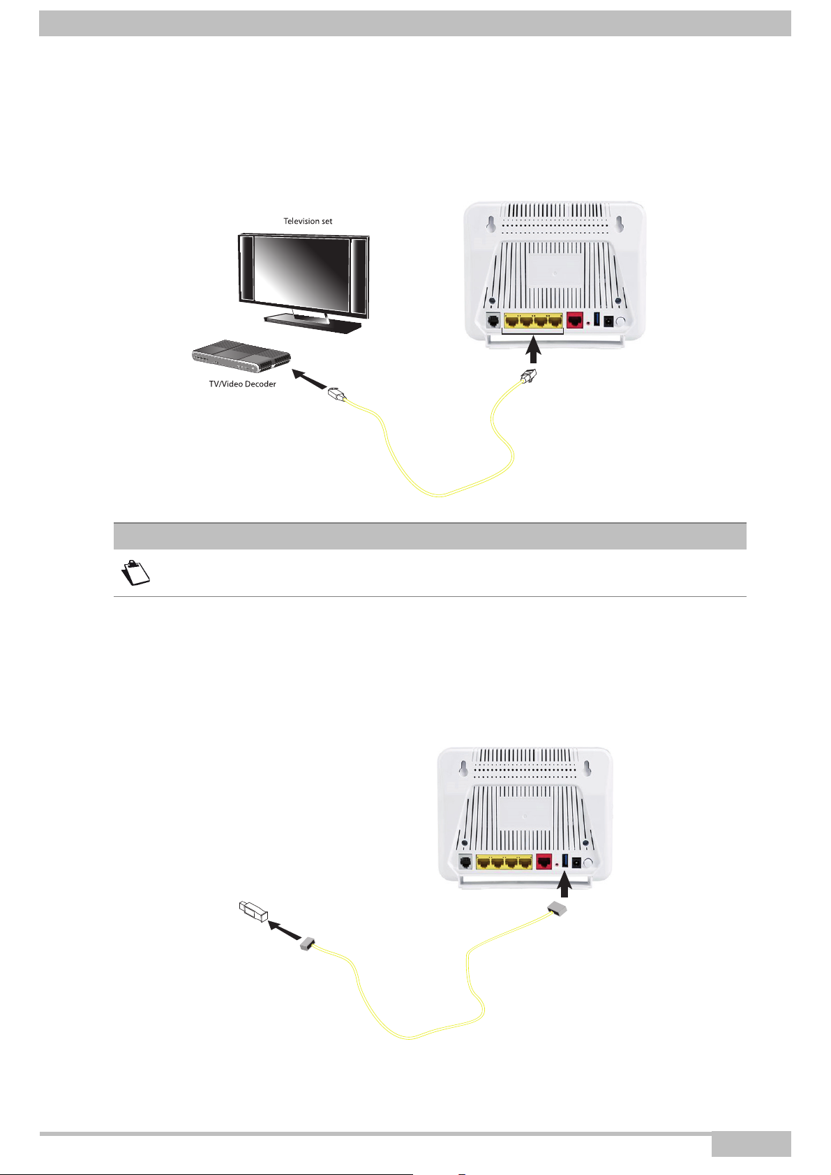
2.3.4 Connecting the Ethernet interface of your router to your TV decoder
1. Connect the end of the yellow Ethernet cable (RJ45/RJ45) supplied in the pack to the Ethernet fixed
connector (marked LAN1, LAN2, LAN3 or LAN4) of your router.
2. Connect the other end of the cable to a TV decoder.
Note
For connection to the decoder, refer to the manufacturer's documentation.
2.3.5 Connecting the USB interface of your router
1. Connect the end of the USB cable (type B Slave female USB Connector) to the USB interface of your
router.
2. Connect the other end of the cable to your USB material (printer, Flash memory, USB key or hard disk).
Figure 2.4 - USB Interface Connection
F@ST 4310 Reference Manual Page 2-9
Sagemcom Broadband SAS document. Reproduction and disclosure prohibited
Page 24

2- Description and connection of router
2.4 Installation safety instructions
Power supply source
• Do not cover the router’s mains adapter.
• The router comes with its own mains adapter. Do not use another adapter.
• This class II adapter does not need to be grounded (earthed). The connection to the electrical network
should comply with the indications given on the label.
• Use a readily accessible mains outlet located near the router. The power supply cord is 1.5 m long.
• Arrange the power supply cord in such a way as to avoid any accidental power cut to the router.
• The router is designed to be connected to a GG- (ground-to-ground) or GN- (ground-toneutral) type
power supply network.
• The router is not designed to be connected to an electrical installation with IT type diagram (neutral
connected to earth through an impedance).
• Protection against short-circuits and leaks between the phase, neutral and earth should be provided by
the building’s electrical installation. The power supply circuit for this equipment should be fitted with 16 A
overcurrent protection and differential protection.
• Connect the router to the mains via a readily accessible wall socket ensuring the electric cutting.
Location conditions
By choosing an appropriate location, you will preserve the longevity of the device. Ensure that the selected
location has the following characteristics:
• Install and use the router inside a building.
• The room temperature must not exceed 45°C.
• The router can be placed on a desktop or fixed vertically in its wall mounting.
• Do not expose the router to strong sunlight or place it near a substantial source of heat.
• Do not place the router in an environment where it could be subjected to considerable steam
condensation.
• Do not expose the router to splashes of water.
• Do not cover the router’s casing.
• Do not use the router or its peripherals for outdoor transmissions.
Maintenance
• Never open the casing. This must be done only by qualified personnel approved by your supplier.
• Do not use liquid or aerosol cleaning agents.
Page 2-10 F@ST 4310 Reference Manual
Sagemcom Broadband SAS document. Reproduction and disclosure prohibited
Page 25

3. Installing and configuring the F@ST 4310 router
F@ST 4310 Reference Manual Page 3-1
Sagemcom Broadband SAS document. Reproduction and disclosure prohibited
Page 26

3- Installing and configuring the F@ST 4310 router
For the installation of the F@ST 4310,
please refer to the Quick Installation Guide of this product.
Page 3-2 F@ST 4310 Reference Manual
Sagemcom Broadband SAS document. Reproduction and disclosure prohibited
Page 27

4. Configuration of network parameters
This section covers • configuring as a DHCP client § 4.1
• reading status of the DHCP server § 4.2
• reading data of the DHCP client § 4.3
F@ST 4310 Reference Manual Page 4-1
Sagemcom Broadband SAS document. Reproduction and disclosure prohibited
Page 28

4- Configuration of network parameters
The aim of this section is:
1. to configure your computer so that it is able to communicate with your router.
2. to display the "Networks" parameters of your router.
Your router implements the DHCP (Dynamic Host Configuration Protocol) server, relay and client functions
in accordance with RFC 2131 and RFC 3132, whereas the computer connected directly to the router or via
a local network by its LAN interface implements only the DHCP client function.
On receipt of a DHCP query from your computer (see ), whether or not it is connected to your router,
the latter responds by indicating:
• an address from the range defined in the configuration,
• the sub-network mask,
• the default gateway (address of your router),
• the address of the gateway as DNS server. The "DNS Relay" function is activated automatically.
Note
Important
The configured range of IP addresses must be the same in the sub-network as in
the LAN interface.
It is imperative that your computer is configured as a DHCP client or that it has a
fixed IP address in the configuration range defined by the DHCP server.
Configuration as a DHCP client is the more commonly used solution.
Page 4-2 F@ST 4310 Reference Manual
Sagemcom Broadband SAS document. Reproduction and disclosure prohibited
Page 29
4- Configuration of network parameters
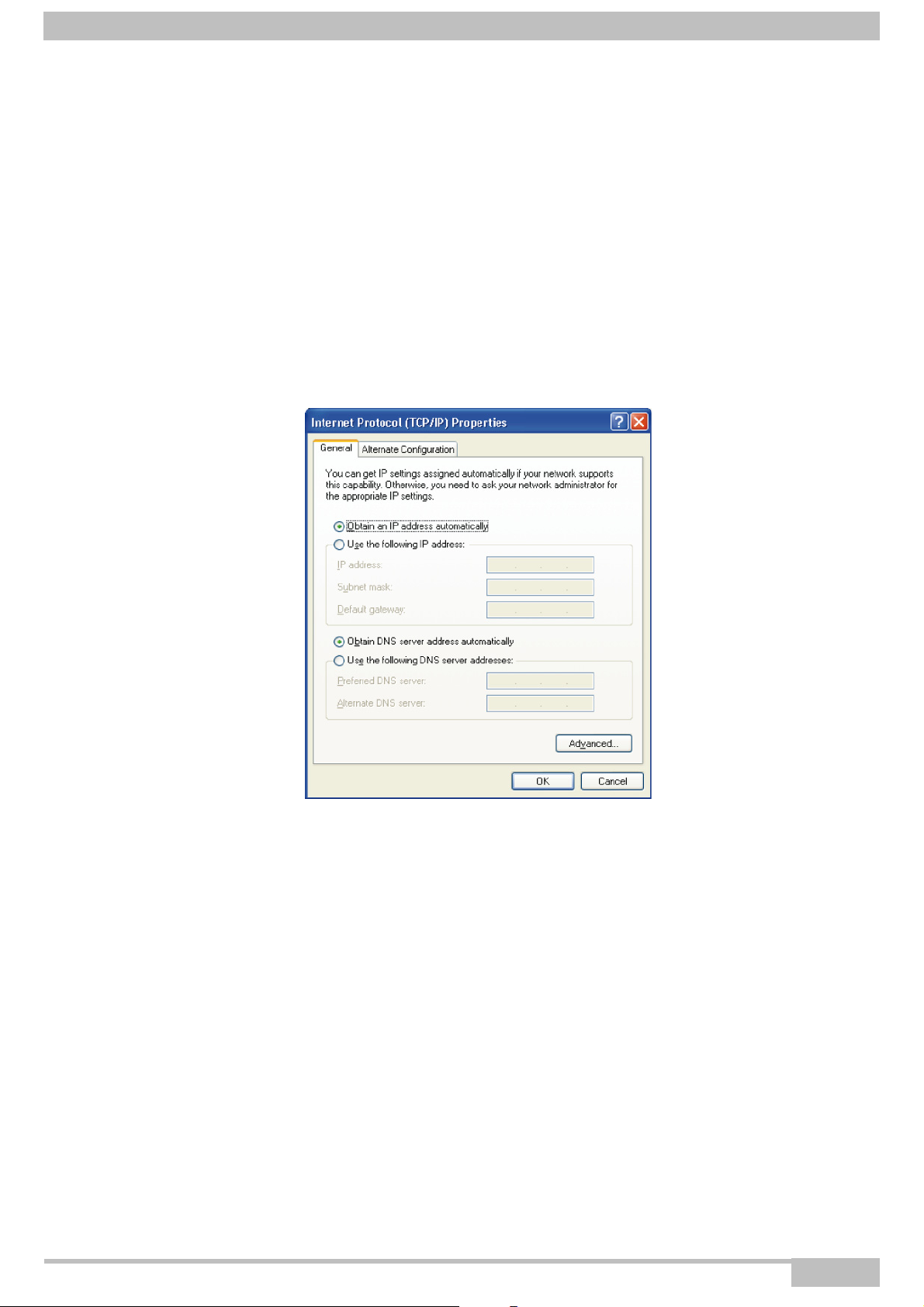
4.1 Configuring as a DHCP client
In Windows XP
1. Click on Start > Control Panel > Network Connections.
2. Right-click the appropriate network, and then select Properties.
The Local Area Connection Properties appears.
3. Select the protocol TCP/IP of the network card, and then click the Properties button.
The screen Internet Protocol (TCP/IP) Properties appears.
4. Select the General tab, then the case "Obtain an IP address automatically" and the case "Obtain
the addresses of the DNS servers automatically".
5. Click the OK button to confirm your choice.
F@ST 4310 Reference Manual Page 4-3
Sagemcom Broadband SAS document. Reproduction and disclosure prohibited
Page 30
4- Configuration of network parameters
4.2 Status of the DHCP server
To obtain the status of the DHCP server:
1. Open your browser.
2. Enter the router’s IP address (by default http://192.168.1.1) or enter the following URL
http://myrouter
3. In the login screen that appears, enter "admin" in the "User Name" field and the "Password" field (see
note).
Note
The User name and Password values are written on the label.
4. Click on the OK button to validate.
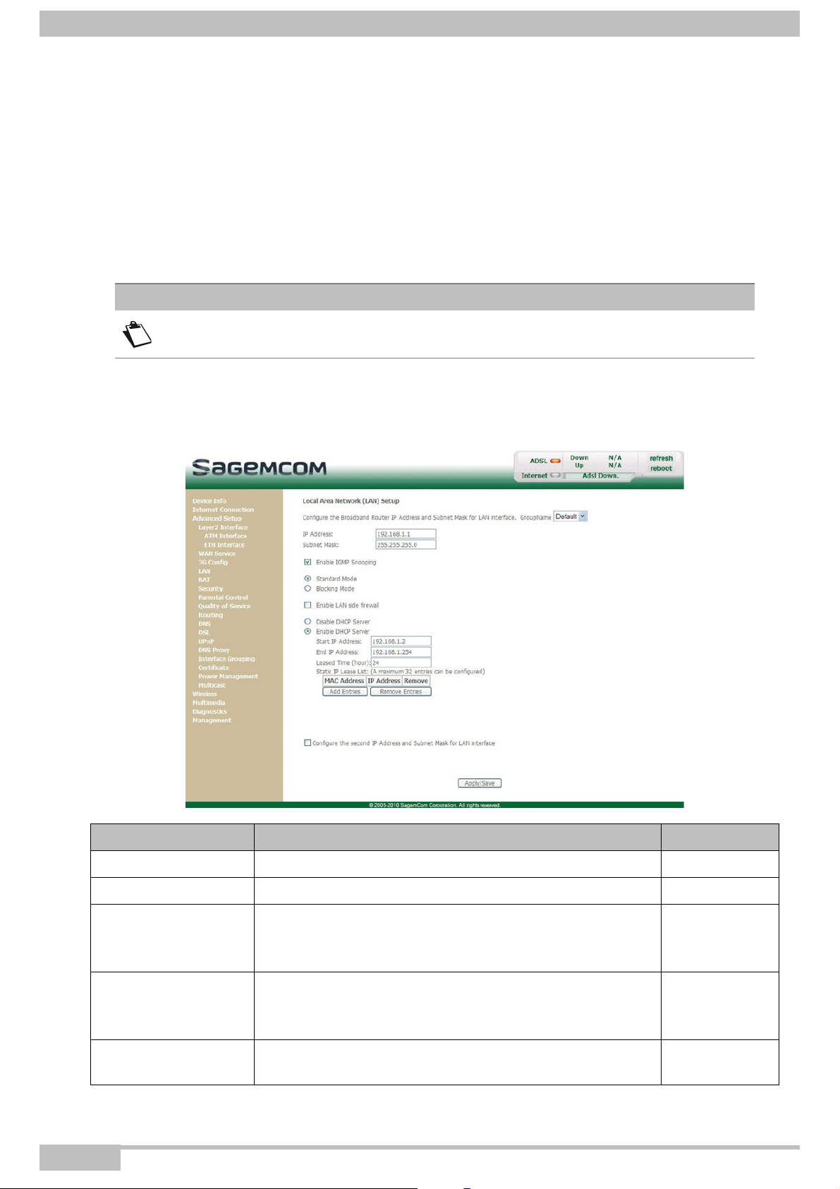
5. Select Advanced Setup menu, then select the LAN menu.
The following screen appears:
Field Description Display
IP Address Displays the sub-network address. 192.168.1.1
Subnet Mask Displays the sub-network mask of the IP network. 255.255.255.0
Displays the first address attributed by the DHCP server.
Start IP Address
End IP Address
Leased Time (hour)
Page 4-4 F@ST 4310 Reference Manual
Note: This IP address must belong to the same
sub-network as that of the local network.
Displays the last address attributed by the DHCP server.
Note: This IP address must belong to the same
sub-network as that of the local network.
Displays the period (in hours) for obtaining an IP address
for a terminal.
Sagemcom Broadband SAS document. Reproduction and disclosure prohibited
192.168.1.2
192.168.1.254
24
Page 31

4.3 Data of the DHCP client
To obtain this data:
In Windows XP
1. Click on Start > Run, enter cmd and then click OK.
The command prompt screen appears.
2. Enter ipconfig /all (or ipconfig/all) then press Enter.
4- Configuration of network parameters
F@ST 4310 Reference Manual Page 4-5
Sagemcom Broadband SAS document. Reproduction and disclosure prohibited
Page 32

4- Configuration of network parameters
Page 4-6 F@ST 4310 Reference Manual
Sagemcom Broadband SAS document. Reproduction and disclosure prohibited
Page 33

5. Information / Configuration
This section covers • Accessing the welcome screen § 5.1
• Recommendations for using the configuration screens § 5.2
• The ADSL connection status § 5.3
• Indications displayed on the display frame located in the
HTTP configurer window
• The ’’Device Info’’ section § 5.5
• The ’’Internet Connection’’ section § 5.6
• The ’’Advanced Setup’’ section § 5.7
• The ’’Wireless’’ section § 5.8
• The "Multimedia" section § 5.9
• The ’’Diagnostics’’ section § 5.10
• The ’’Management’’ section § 5.11
§5.4
F@ST 4310 Reference Manual Page 5-1
Sagemcom Broadband SAS document. Reproduction and disclosure prohibited
Page 34

5- Information / Configuration
5.1 Accessing the welcome screen
Note
To access this screen, you must have configured one of your computer's interfaces
using the installation CD-ROM provided with your router (see section 3.).
If you are using your computer's Ethernet card to configure your router, connect it to an Ethernet port (LAN1
to LAN4).
Your router is then configured using a simple Web browser (e.g. Internet Explorer).
Note
The router's DHCP server function is activated by default with an address range
defined as indicated in subsection.6.4.4.
To access the configurer, proceed as follows:
To obtain the status of the DHCP server:
1. Click on Start > All Programs > F@ST 4310 > Configuration.
2. In the login screen that appears, enter your identification information.
By default, the identification information is:
Username: admin
Password: (see on the label)
Note
The equipment's IP address (192.168.1.1) appears in the header bar.
3. Click on OK to validate.
Page 5-2 F@ST 4310 Reference Manual
Sagemcom Broadband SAS document. Reproduction and disclosure prohibited
Page 35

5- Information / Configuration
4. Your computer’s Web browser opens and displays the welcome screen of the router’s HTTP
configuration tool..
The configuration menus appear on the left hand side panel.
The HTTP configuration tool opens by default on the Device Info menu:
• the centre panel shows router’s information and the current ADSL connection status (see subsection
5.3).
• the router’s activity and status is always available at the top right corner, as a box which lets you know
the status of the ADSL line, lets you refresh the data displayed and restart your router at any time (see
subsection 5.4).
left hand side panel gives you access to the router’s configuration menus and submenus (see
subsection 5.5 to 5.11).
Note
You can modify the password to access your router's configuration tool to optimise
the safety of your network.
F@ST 4310 Reference Manual Page 5-3
Sagemcom Broadband SAS document. Reproduction and disclosure prohibited
Page 36

5- Information / Configuration
5.2 Recommendations
The meaning of the main buttons most commonly present in all the configuration windows is provided in the
table below.
Button Description
Click on this button to add a new window to fill in the fields used to add an object.
Click on this button to return to the previous screen.
Click on this button to close the active window and return to the main screen.
Click on this button to display a new window to modify the fields that can be
accessed for a previously selected object.
Click on this button to display the next screen.
Click on this button to remove a selected object from a list.
Note: You must check the "Remove" box to delete this object.
Click on this button to save the entry in the router's non-volatile (flash) memory.
Note: This value will only be taken into account when you restart your router.
Click on this button to save the entry in the router's non-volatile (flash) memory.
Note: This value will be taken into account immediately without you having to
restart your router.
Click on this button to save the entry in the router's non-volatile (flash) memory
then restart your computer.
Basic principles
1. To make this guide easier to read and understand, it does not state that each time you enter
information into a screen you must click on Save or Apply/Save or Save/Reboot (except, of course, if
this is necessary).
2. When you select a section, the screen for the first menu in the section is displayed. In the same way,
when you select a menu, the screen for the first sub-menu is displayed.
3. All the fields in the different screens are explained in a table.
Page 5-4 F@ST 4310 Reference Manual
Sagemcom Broadband SAS document. Reproduction and disclosure prohibited
Page 37

5- Information / Configuration
5.3 ADSL connection status
Refer to subsection 6.2.1 - /Summary.
5.4 Display frame
The router’s activity status is always visible at the left corner or the top right of the HTTP configuration tool.
You can perform the following actions:
• click on Refresh to update the data displayed
• click on Reboot to restart your router
ADSL information
The following table presents the possible states of the ADSL field:
Status Meaning
Green ADSL line synchronised
Yellow ADSL line synchronising
Red ADSL line not connected
The Down field displays the nominal downlink bit rate.
The Up field displays the nominal uplink bit rate.
Internet information
The following table presents the possible states of the Internet field:
Status Status Meaning
ADSL Down ADSL line not connected or not activated
Off
Green Connected The Internet connection has succeeded
Yellow Waiting for ISP Connecting to the Internet service
Red Access denied Incorrect Internet account
F@ST 4310 Reference Manual Page 5-5
Not configured The Internet account must be configured
Router rebooting Router is rebooting
Sagemcom Broadband SAS document. Reproduction and disclosure prohibited
Page 38
5- Information / Configuration
5.5 Device Info
Clicking on this heading displays the following menus:
• Summary (see subsection 5.5.1)
• WAN (see subsection 5.5.2)
• 3G Status (see subsection 5.5.3)
• Statistics (see subsection 5.5.4)
• Route (see subsection 5.5.5)
• ARP (see subsection 5.5.6)
• DHCP (see subsection 5.5.7)
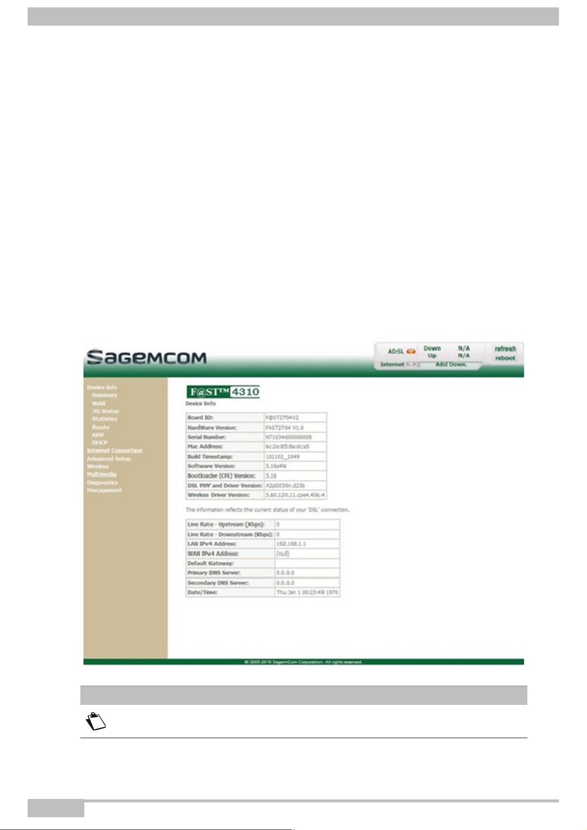
5.5.1 Summary
Object: This menu lets you display the current status of your Internet connection.
• In the Device Info menu, select Summary.
The following screen opens:
Note
This screen also appears in the welcome screen (see subsection 5.1).
Page 5-6 F@ST 4310 Reference Manual
Sagemcom Broadband SAS document. Reproduction and disclosure prohibited
Page 39

5- Information / Configuration
The following table provides the meaning of the different fields which are displayed.
Field Meaning
Board ID Router model
HardWare Version Hardware version of the router
Serial Number Serial number of the router
Mac Address Mac address of the router
Software Version Software version currently installed on the router
Bootloader (CFE) Version Bootloader version currently installed on the router
Wireless Driver Version Software version of the wireless card installed on the router
Line Rate - Upstream (kbps) Nominal up line rate
Line Rate - Downstream (kbps) Nominal down line rate
LAN IPv4 Address Local network IPv4 address (LAN)
WAN IPv4 Address Remote network IPv4 address (WAN)
Default Gateway Default gateway address
Primary DNS Server Primary DNS server address
Secondary DNS Server Secondary DNS server address
LAN IPv6 ULA Address Local network IPv6 address (LAN)
Default IPv6 Gateway Default gateway IPv6 address
5.5.2 WAN
Object: This menu is used to display all the parameters which concern the remote network.
• In the Device Info menu, select WAN.
The following screen opens:
F@ST 4310 Reference Manual Page 5-7
Sagemcom Broadband SAS document. Reproduction and disclosure prohibited
Page 40

5- Information / Configuration
5.5.3 3G Status
Object: This menu is used to display all the parameters which concern 3G connection.
• In the Device Info menu, select 3G Status.
The following screen opens:
5.5.4 Statistics
Object: This menu is used to display all the router's statistics.
This menu contains the following sub menus:
• LAN (see subsection 5.5.4.1)
• WAN Service (see subsection 5.5.4.2)
• xTM (see subsection 5.5.4.3)
• xDSL (see subsection 5.5.4.4)
Page 5-8 F@ST 4310 Reference Manual
Sagemcom Broadband SAS document. Reproduction and disclosure prohibited
Page 41

5- Information / Configuration
5.5.4.1 LAN
Object: This menu is used to display all the parameters which concern the local network (LAN).
• In the Device Info menu, select Statistics then select LAN.
The following screen opens:
• Click on the Reset Statistics button to reset statistics.
F@ST 4310 Reference Manual Page 5-9
Sagemcom Broadband SAS document. Reproduction and disclosure prohibited
Page 42

5- Information / Configuration
5.5.4.2 WAN Service
Object: This menu is used to display all the parameters which concern the remote network (WAN).
• In the Device Info menu, select Statistics then select WAN Service.
The following screen opens:
• Click on the Reset Statistics button to reset statistics.
Page 5-10 F@ST 4310 Reference Manual
Sagemcom Broadband SAS document. Reproduction and disclosure prohibited
Page 43

5.5.4.3 xTM
Object: This menu is used to display all the xTM statistics of the line.
• In the Device Info menu, select Statistics then select xTM.
The following screen opens:
5- Information / Configuration
• Click on the Reset button to reset statistics.
F@ST 4310 Reference Manual Page 5-11
Sagemcom Broadband SAS document. Reproduction and disclosure prohibited
Page 44

5- Information / Configuration
5.5.4.4 xDSL
Object: This menu is used to display all the xDSL statistics of the line.
• In the Device Info menu, select Statistics then select xDSL.
The following screen opens:
• Click on the Reset Statistics button to reset statistics.
• Click on the xDSL BER Test button to display the following screen:
• In the Tested Time (sec) field, select the test time from the scroll down list.
• Click on the Start button to run the test. The results are displayed once the tests are completed.
• Click on the Close button to close the window and return to the previous screen.
Page 5-12 F@ST 4310 Reference Manual
Sagemcom Broadband SAS document. Reproduction and disclosure prohibited
Page 45

5- Information / Configuration
5.5.5 Route
Object: This menu is used to display all the information concerning your router's routing.
• In the Device Info menu, select Route.
The following screen opens:
F@ST 4310 Reference Manual Page 5-13
Sagemcom Broadband SAS document. Reproduction and disclosure prohibited
Page 46

5- Information / Configuration
5.5.6 ARP
Object: This menu is used to display all the information concerning address resolution (ARP: Address
Resolution Protocol). This shows the physical address of a computer's network card,
corresponding to an IP address.
• In the Device Info menu, select ARP.
The following screen opens:
Page 5-14 F@ST 4310 Reference Manual
Sagemcom Broadband SAS document. Reproduction and disclosure prohibited
Page 47

5- Information / Configuration
5.5.7 DHCP
Object: This menu is used to display all the computers which obtained an IP address from the router's
DHCP server.
• In the Device Info menu, select DHCP.
The following screen opens:
F@ST 4310 Reference Manual Page 5-15
Sagemcom Broadband SAS document. Reproduction and disclosure prohibited
Page 48

5- Information / Configuration
5.6 Internet Connection
Object: This menu lets you enter your connection ID and your connection password.
• Select the Internet Connection menu.
The following screen opens:
Field Action
PPP Username
PPP Password
Important
If the message "There is no ppp connection" appears, this means that the remote
network (WAN) parameters have not been filled in (see subsection
5.7.2 - Advanced Setup > WAN Service).
Enter your connection ID.
This information is provided to you by your Internet Service
Provider (ISP).
Enter your connection password.
This information is provided to you by your Internet Service
Provider (ISP).
Default
value
-
-
Disconnect
When you click on the button Disconnect:
• Internet access is no longer possible.
• In the supervision box, the “Internet” indicator switches off and the message “Connected” is replaced
by “PPP disconnected”.
• On the front panel of the router, the indicator goes out.
Page 5-16 F@ST 4310 Reference Manual
Sagemcom Broadband SAS document. Reproduction and disclosure prohibited
Page 49

5.7 Advanced Setup
Object: This menu is used to configure the specific parameters for your router.
Important
This menu must only be used by experienced users.
This section contains the following menus:
• Layer2 Interface (see subsection 5.7.1)
• WAN Service (see subsection 5.7.2)
• 3G Config (see subsection 5.7.3)
• LAN (see subsection 5.7.4)
• NAT (see subsection 5.7.5)
• Security (see subsection 5.7.6)
• Parental Control (see subsection 5.7.7)
5- Information / Configuration
• Quality of Service (see subsection 5.7.8)
• Routing (see subsection 5.7.9)
• DNS (see subsection 5.7.10)
• DSL (see subsection 5.7.11)
• Upnp (see subsection 5.7.12)
• DNS Proxy (see subsection 5.7.13)
• Interface Grouping (see subsection 5.7.14)
• Certificate (see subsection 5.7.15)
• Power Management (see subsection 5.7.16)
• Multicast (see subsection 5.7.17)
Note
The menu Quality of Service only appears if you checked the "Enable Quality Of
Service" box in the WAN interface configuration screen (see Advanced
Setup>WAN Service - subsection 5.7.2>Add).
F@ST 4310 Reference Manual Page 5-17
Sagemcom Broadband SAS document. Reproduction and disclosure prohibited
Page 50

5- Information / Configuration
5.7.1 Layer2 Interface
Object: This menu is used to configure DSL interfaces.
This section contains the following menus:
• ATM Interface (see subsection 5.7.1.1)
• ETH Interface (see subsection 5.7.1.3)
5.7.1.1 ATM Interface
Object: This menu is used to configure DSL ATM interfaces.
• In the Advanced Setup menu, select Layer2 Interface then ATM I nterface.
The following screen opens:
Field Meaning
Interface Name of the DSL ATM interface, allocated automatically.
Vpi Value of the VPI.
Vci Value of the VCI.
DSL Latency DSL Latency.
Category Type of service adapter to the traffic.
Link Type Protocol used in the DSL ATM interface.
Connection Mode Connection mode (Default mode, VLAN MUX Mode or MSC Mode).
IP Qos Status (Enabled or Disabled) of the Quality of Service function.
Page 5-18 F@ST 4310 Reference Manual
Sagemcom Broadband SAS document. Reproduction and disclosure prohibited
Page 51

Field Meaning
Scheduler Alg
5- Information / Configuration
Value defined to perform multitasking (execute more than one
process at a time) and multiplexing (transmit multiple flows
simultaneously).
Queue Weight
Remove
Value defined to give the queue a priority (called a weight) versus the
other queues.
Check this box and click on the [Remove] button to remove the
selected object from the list.
5.7.1.2 Add
• Click on the Add button to display the following screen:
ATM PVC Configuration
Field Action
VPI
VCI
Enter a VPI value
Enter a VPI value
a
between 0 and 255.
a.
between 32 and 65535.
Select the DSL Latency:
Select DSL
Latency
• Path0
• Path1
F@ST 4310 Reference Manual Page 5-19
Sagemcom Broadband SAS document. Reproduction and disclosure prohibited
Default
value
0
32
Page 52

5- Information / Configuration
Field Action
Select DSL Link
Type
Select Connection
Mode
Encapsulation
mode
Service Category
Select the type of network protocol from the scroll down list:
• EoA: Ethernet over ATM
• PPPoA: PPP over ATM
• IPoA: IP over ATM
Note: EoA is for PPPoE and IPoE.
Select the connection mode:
• Default Mode - Single service over one connection
• VLAN MUX Mode - Multiple Vlan service over one connection
For more details, a summary table is presented below for each
type of protocol.
Select the encapsulation mode for the selected DSL link type.
For more details, a summary table is presented below for each
type of protocol.
Select the type of service adapter to the traffic from the scroll
down list:
• UBR without PCR: Unspecified Bit Rate
• UBR with PCR: Unspecified Bit Rate
• CBR: Constant Bit Rate
• Non Realtime VBR: Variable Bit Rate
• Realtime VBR: Variable Bit Rate
Default
value
EoA
LLC/SNAP
-
BRIDGING
UBR
without
PCR
• Strict Priority
Select IP QoS
Scheduler
Algorithm
-Precedence of the lowest queue:
• Weighted Fair Queuing
-Weight Value of the default queue: [1-63]
8 (lowest)
-MPAAL Group of Precedence:
Enter a maximum number of cells transmitted per second,
Peak Cell Rate
Sustainable Cell
c
Rate
Maximum Burst
c.
Size
a. This value is delivered to you by your Internet Service Provider (ISP).
b. This field only appears when the "UBR with PCR", "CBR", "Non Realtime VBR" or "Realtime VBR" type
of service is selected.
c. These fields only appear when the "Non Realtime VBR" or "Realtime VBR" type of service is selected.
b
between 1 and 2491.
Enter an average number of cells transmitted per second.
Note: This number must be lower than the Peak Cell
Rate (PCR).
Enter the maximum number of cells emitted in burst (value
between 1 and 1000 000).
1
8
-
-
-
Page 5-20 F@ST 4310 Reference Manual
Sagemcom Broadband SAS document. Reproduction and disclosure prohibited
Page 53

5- Information / Configuration
Select Connection Mode
The Connection Mode selection only appears if you have selected the EoA DSL link type.
Field Action
Default mode Check this box to configure a single service over one connection. Checked
VLAN MUX Mode
Check this box to configure Multiple Vlan service over one
connection.
Encapsulation modes
DSL Link type Action
Select the encapsulation of your choice from the scroll down list.
EoA
(Ethernet over ATM)
PPPoA
(PPP over ATM)
IPoA
(IP over ATM)
• LLC/SNAP-BRIDGING
• VC/MUX
Select the encapsulation of your choice from the scroll down list.
• VC/MUX
• LLC/ENCAPSULATION
Select the encapsulation of your choice from the scroll down list.
• LLC/SNAP-ROUTING
• VC/MUX
Default
value
Not
checked
Default
value
LLC/SNAP-
BRIDGING
VC/MUX
LLC/SNAP-
ROUTING
5.7.1.3 ETH Interface
Object: This menu is used to configure DSL ETH interfaces.
• In the Advanced Setup menu, select Layer2 Interface then ETH Interface.
The following screen opens:
F@ST 4310 Reference Manual Page 5-21
Sagemcom Broadband SAS document. Reproduction and disclosure prohibited
Page 54

5- Information / Configuration
5.7.1.4 Add
• Click on the Add button to display the following screen:
DSL Link type Action
Select a ETH port
Select the encapsulation of your choice from the scroll down list
(from 1 to 3).
Select the connection mode of your choice from the scroll down
Select Connection
Mode
list.
• Default Mode - Single service over one connection
• VLAN MUX Mode - Multiple Vlan service over one connection
• Click on the Apply/Save button to confirm the creation of the new ETH interface.
Default
value
eth0/eth0
Default
Mode
checked
Page 5-22 F@ST 4310 Reference Manual
Sagemcom Broadband SAS document. Reproduction and disclosure prohibited
Page 55

5- Information / Configuration
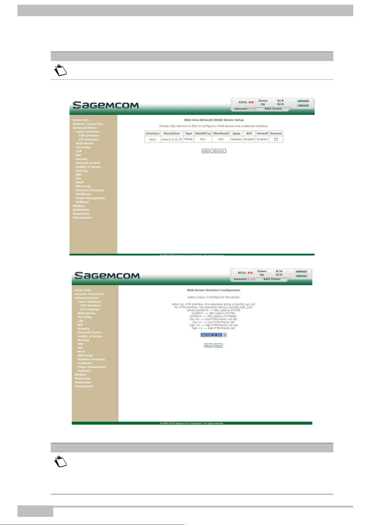
5.7.2 WAN Service
Object: This menu is associated with the remote network. It is used to display the list of all the configured
PVCs, and to add PVCs or remove them.
• In the Advanced Setup menu, select WAN Service.
The following screen opens:
Field Meaning
Interface Name, allocated automatically, associated with the service name (for example, ppp0).
Description
Name of the ATM service. This name is made up as follows: Protocol_VPI_VCI_Index
For example: pppoe_0_8_32.
Type Data flow encapsulation mode.
a
Vlan8021p
VlanMuxId
Value of the 802.1P Priority.
a.
Value of the 802.1Q VLAN ID.
Status (Enabled or Disabled) of the Igmp function.
Igmp
Note: This function enables the distribution of Multicast datagrams over the local
network (LAN) and interaction between the router and the local network hosts.
NAT Status (Enabled or Disabled) of the NAT.
Firewall Status (Enabled or Disabled) of the Firewall.
Remove
a. These values only appear if the WAN service is configured over a DSL ATM interface using VLAN MUX
Mode.
Check this box and clik on the [Remove] button to remove the selected object from
the list.
F@ST 4310 Reference Manual Page 5-23
Sagemcom Broadband SAS document. Reproduction and disclosure prohibited
Page 56
5- Information / Configuration
5.7.2.1 Add
Note
You must have configured a DSL ATM interface (see section 5.7.1) to add a WAN
service.
• Click on the Add button.
• Select the DSL ATM interface for the WAN service.
• Click on the Next button to continue configuring the WAN service.
Note
Depending on the type of network protocol configured for the selected DSL ATM
interface (EoA, PPPoA or IPoA), the content of the following WAN interface
configuration screens differs.
Therefore, and for more clarity, each type of protocol will be dealt with separately
(screens + associated summary tables) below.
Page 5-24 F@ST 4310 Reference Manual
Sagemcom Broadband SAS document. Reproduction and disclosure prohibited
Page 57

5.7.2.2 Ethernet over ATM – PPP over Ethernet (PPPoE)
• Select the WAN service type PPP over Ethernet (PPPoE).
5- Information / Configuration
Field Action Default value
Enter Service
Description
Displays the name of the service being configured. This
name, which is allocated automatically, is made up as
follows: Protocol_VPI_ Index _ VCI
For example: pppoe_eth0.
pppoe_eth0
Note: You may enter another service name.
Enter a value for the 802.1P Priority. This value is
Enter 802.1P Priority
Enter 802.1Q VLAN ID
a. These values only appear if the WAN service is configured over a DSL ATM interface using VLAN MUX
Mode.
a
between 0 and 7.
Enter a value for the 802.1QVLAN ID. This value is
a.
between 0 and 4094.
-1
-1
F@ST 4310 Reference Manual Page 5-25
Sagemcom Broadband SAS document. Reproduction and disclosure prohibited
Page 58

5- Information / Configuration
• Click on the Next button to continue configuring the WAN service.
Field Action
PPP Username
PPP Password
PPPoE Service Name
Authentication Method
Dial on demand
(with idle timeout timer)
Default
value
Enter your connection ID.
-
This information is provided to you by your Internet Service
Provider (ISP).
Enter your connection password.
-
This information is provided to you by your Internet Service
Provider (ISP).
Enter the name of the PPPoE service.
-
This information is provided to you by your Internet Service
Provider (ISP).
Select the authentication method of your choice from the scroll
AUTO
down list:
• AUTO
• PAP
• CHAP
• MSCHAP
Check the box to connect to the Internet only when needed. Not
Checked
Page 5-26 F@ST 4310 Reference Manual
Sagemcom Broadband SAS document. Reproduction and disclosure prohibited
Page 59

5- Information / Configuration
Field Action
Inactivity Timeout
(minutes):[1-4320]
a
PPP retry on
authentication error
PPP retry period
(seconds) ):[3-65535]
b
PPP MTU (Bytes)
Use Static IPv4 Address
IPv4 Address
c
Enable PPP Debug
mode
Default
value
Enter the inactivity time. This value (in minutes) is between 1
0
and 4320 (i.e. 72 hours).
If there is no Internet traffic for this period of time, the PPPoE
session is interrupted.
Check the box, PPP can be retried again and again while
Checked
authentication fails.
Enter if required a retry period. This value (in seconds) is by
15
default set to 15 seconds. You can set another value from 3 to
65535.
Enter an MTU (Maximum Transfer Unit) value. This value (in
1492
bytes) is between 38 and 1492.
Note: The MTU specifies the maximum size of the data used
(IP packets) expressed as a number of bytes.
Check the box to use the static IPv4 address. Not
checked
Enter the static IPv4 address. 0.0.0.0
Check the box to use the PPP Debug mode.
In the event of connection failure, this option will enable you to
Not
checked
trace a possible problem in the SYSLOG file.
Bridge PPPoE frames
between WAN and Local
Check the box to enable the router when bridging the frames
between WAN and local Ethernet ports.
Ports
Enable IGMP Multicast
Check the box to activate the IGMP function. Not
Proxy
a. This field only appears when the "PPP retry on authentication error" field is activated (box checked).
b. This field only appears when the "PPP retry on authentication error" field is activated (box checked).
c. This field only appears when the "Use Static IPv4 Address" field is activated (box checked).
• Click on the Next button to continue configuring the remote network (WAN) in PPPoE mode.
Not
checked
checked
F@ST 4310 Reference Manual Page 5-27
Sagemcom Broadband SAS document. Reproduction and disclosure prohibited
Page 60

5- Information / Configuration
• Select a preferred WAN interface as the system default gateway.
• Click on the Next button to continue configuring the remote network (WAN) in PPPoE mode.
Field Action Default value
Select DNS Server
Interface from available
WAN interfaces
Page 5-28 F@ST 4310 Reference Manual
For more details, a summary table is presented below
for each column. ppp1
pppoa2
Sagemcom Broadband SAS document. Reproduction and disclosure prohibited
Page 61

5- Information / Configuration
Field Action Default value
Use the following Static
DNS IP address
If you check this box, you must enter DNS server
addresses.
Not checked
Primary DNS server Enter a primary DNS server address. -
Secondary DNS server Enter a secondary DNS server address. -
Select DNS Server Interface from available WAN interfaces
Button Action
Transfer the interfaces selected in the Available WAN
• Click on the Next button to continue configuring the remote network (WAN) in PPPoE mode.
Interfaces area to the Selected DNS Server Interfaces area.
Transfer the interfaces selected in the Selected DNS Server
Interfaces area to the Available WAN Interfaces area.
Field Description
NAT Displays the status of the NAT.
Firewall Displays the status of the firewall.
IGMP Multicast Displays the status of the IGMP function.
Quality of Service Displays the status of the Quality of Service function.
• Click on the Apply/Save button to confirm the new WAN service.
F@ST 4310 Reference Manual Page 5-29
Sagemcom Broadband SAS document. Reproduction and disclosure prohibited
Page 62

5- Information / Configuration
5.7.2.3 Ethernet over ATM – IP over Ethernet (IPoE)
• Select the WAN service type IP over Ethernet (IPoE).
Field Action Default value
Enter Service
Description
Displays the name of the service being configured. This
name, which is allocated automatically, is made up as
follows: Protocol_VPI_ Index _ VCI
For example: ipoe_eth0.
ipoe_eth0
Note: You may enter another service name.
Enter a value for the 802.1P Priority. This value is between
Enter 802.1P Priority
Enter 802.1Q VLAN ID
a. These values only appear if the WAN service is configured over a DSL ATM interface using VLAN MUX
Mode.
a
0 and 7.
Enter a value for the 802.1QVLAN ID. This value is
a.
between 0 and 4094.
-1
-1
Page 5-30 F@ST 4310 Reference Manual
Sagemcom Broadband SAS document. Reproduction and disclosure prohibited
Page 63

• Click on the Next button to continue configuring the WAN service.
5- Information / Configuration
Field Action
Obtain an IP address
automatically
Option 60 Vendor ID
Option 61 IAID
Option 61 DUID
Option 125
Use the following
Static IP address:
Check the box to obtain an IP address automatically from your
router's DHCP server.
This feature allows a DHCP server to differentiate between the two
kinds of client machines and process the requests from the two
types of modems appropriately.
If this feature is enabled on the DHCP server, and you want to use
it, enter the vendor ID.
This features allows a DHCP server to use an Identity Association
IDentifier (IAID).
If this feature is enabled on the DHCP server, and you want to use
it, enter the DHCP Identity Association ID.
This features allows a DHCP server to use a DHCP Unique
IDentifier (DUID).
If this feature is enabled on the DHCP server, and you want to use
it, enter the DHCP Unique IDentifier.
This feature allows you to enable/disable the DHCP
Vendor-Identifying Vendor-Specific 125 option.
If you check this box, you must enter a static WAN IP address and
the dedicated WAN subnet mask and WAN gateway IP address.
Default
value
Checked
-
-
-
Disable
Not
checked
WAN IP Address Enter the static IP address. -
WAN Subnet Mask Enter the subnet mask. -
WAN gateway IP
Enter the gateway IP address. -
address
F@ST 4310 Reference Manual Page 5-31
Sagemcom Broadband SAS document. Reproduction and disclosure prohibited
Page 64

5- Information / Configuration
• Click on the Next button to continue configuring the remote network (WAN) in IPoE mode.
Field Action Default value
Check the box to activate the NAT function.
Not checked
Note: NAT is a configurable IP address
Enable NAT
translation function which will be applied
to the interfaces of your router which you
will have activated for this function.
Enable Fullcone NAT
Check the box to activate the Fullcone NAT
a
function.
Not checked
Enable Firewall Check the box to activate the Firewall service. Not checked
Enable IGMP Multicast Check the box to activate the IGMP function. Not checked
a. This field only appears when the "Enable NAT" field is activated (box checked).
Page 5-32 F@ST 4310 Reference Manual
Sagemcom Broadband SAS document. Reproduction and disclosure prohibited
Page 65

• Select a preferred WAN interface as the system default gateway.
5- Information / Configuration
• Click on the Next button to continue configuring the remote network (WAN) in IPoE mode.
Field Action
Selected DNS Server
Interfaces
For more details, a summary table is presented below
for each column.
Available WAN
Interfaces
Primary DNS server Enter the primary DNS server
Secondary DNS server Enter the primary DNS server
F@ST 4310 Reference Manual Page 5-33
Sagemcom Broadband SAS document. Reproduction and disclosure prohibited
Page 66

5- Information / Configuration
Select DNS Server Interface from available WAN interfaces
Button Action
Transfer the interfaces selected in the Available WAN
• Click on the Next button to continue configuring the remote network (WAN) in IPoE mode.
Interfaces area to the Selected DNS Server Interfaces area.
Transfer the interfaces selected in the Selected DNS Server
Interfaces area to the Available WAN Interfaces area.
Field Description
Connection Type Displays the "IPoE" protocol
NAT Displays the status of the NAT.
Firewall Displays the status of the firewall.
IGMP Multicast Displays the status of the IGMP function.
Quality Of Service Displays the status of the Quality Of Service function.
• Click on the Apply/Save button to confirm the new WAN service.
Page 5-34 F@ST 4310 Reference Manual
Sagemcom Broadband SAS document. Reproduction and disclosure prohibited
Page 67

5.7.2.4 Ethernet over ATM - Bridging
• Select the WAN service type Bridging.
5- Information / Configuration
Field Action
Enter Service
description
Displays the name of the service being configured. This name,
which is allocated automatically, is made up as follows:
Protocol_VPI_ Index _ VCI
For example: br_0_8_32.
Default
br_0_8_32
Note: You may enter another service name.
Enter a value for the 802.1P Priority. This value is between 0
Enter 802.1P Priority
Enter 802.1Q VLAN ID
a. These values only appear if the WAN service is configured over a DSL ATM interface using VLAN MUX
Mode.
a
and 7.
Enter a value for the 802.1QVLAN ID. This value is between 0
a.
and 4094.
value
-1
-1
F@ST 4310 Reference Manual Page 5-35
Sagemcom Broadband SAS document. Reproduction and disclosure prohibited
Page 68

5- Information / Configuration
• Click on the Next button to continue configuring the remote network (WAN) in Bridge mode.
Field Description
NAT Displays the status of the NAT.
Firewall Displays the status of the firewall.
IGMP Multicast In the "Bridge" connection, this field is: Not Applicable
Quality Of Service Displays the status of the Quality Of Service function.
• Click on the Apply/Save button to confirm the new WAN service.
Page 5-36 F@ST 4310 Reference Manual
Sagemcom Broadband SAS document. Reproduction and disclosure prohibited
Page 69

5.7.2.5 PPP over ATM (PPPoA)
5- Information / Configuration
Field Action Default value
Enter Service
Description
Displays the name of the service being configured. This
name, which is allocated automatically, is made up as
follows: Protocol_VPI_ Index_VCI
For example: pppoa_0_0_35.
Note: You may enter another service name.
pppoa_0_0_35
F@ST 4310 Reference Manual Page 5-37
Sagemcom Broadband SAS document. Reproduction and disclosure prohibited
Page 70

5- Information / Configuration
• Click on the Next button to continue configuring the WAN service.
Field Action
PPP Username
PPP Password
Authentication Method
Dial on demand
(with idle timeout timer)
PPP retry on
authentication error
PPP retry period
(seconds)
a
Default
value
Enter your connection ID.
-
This information is provided to you by your Internet Service
Provider (ISP).
Enter your connection password.
-
This information is provided to you by your Internet Service
Provider (ISP).
Select the authentication method of your choice from the scroll
AUTO
down list:
• AUTO
• PAP
• CHAP
• MSCHAP
Check the box to connect to the Internet only when needed. Not
checked
Check the box, PPP can be retried again and again while
Checked
authentication fails
Enter if required a retry period. This value (in seconds) is by
15
default set to 15 seconds. You can set another value from 3 to
65535.
Page 5-38 F@ST 4310 Reference Manual
Sagemcom Broadband SAS document. Reproduction and disclosure prohibited
Page 71

5- Information / Configuration
Field Action
Enter an MTU (Maximum Transfer Unit) value. This value (in
PPP MTU (Bytes)
bytes) is between 46 and 1500.
Note: The MTU specifies the maximum size of the data used
(IP packets) expressed as a number of bytes.
Use Static IPv4 Address
IPv4 Address:
b
Enable PPP Debug
Mode
Enable IGMP Multicast
Check the box to use the static IPv4 address. Not
Enter the static IPv4 address. 0.0.0.0
Check the box to use the PPP Debug mode.
In the event of connection failure, this option will enable you to
trace a possible problem in the SYSLOG file.
Check the box to activate the IGMP function. Not
Proxy
a. This field only appears when the "PPP retry on authentication error" field is activated (box checked).
b. This field only appears when the "Use Static IPv4 Address" field is activated (box checked).
• Click on the Next button to continue configuring the remote network (WAN) in PPPoA mode.
• Select a preferred WAN interface as the system default gateway.
Default
value
1500
checked
Not
checked
checked
F@ST 4310 Reference Manual Page 5-39
Sagemcom Broadband SAS document. Reproduction and disclosure prohibited
Page 72

5- Information / Configuration
• Click on the Next button to continue configuring the remote network (WAN) in PPPoA mode.
Field Action
Selected DNS Server
Interfaces
For more details, a summary table is presented below
for each column.
Available WAN
Interfaces
Primary DNS server Enter the primary DNS server
Secondary DNS server Enter the primary DNS server
Select DNS Server Interface from available WAN interfaces
Button Action
Transfer the interfaces selected in the Available WAN
Interfaces area to the Selected DNS Server Interfaces area.
Transfer the interfaces selected in the Selected DNS Server
Interfaces area to the Available WAN Interfaces area.
Page 5-40 F@ST 4310 Reference Manual
Sagemcom Broadband SAS document. Reproduction and disclosure prohibited
Page 73

5- Information / Configuration
• Click on the Next button to continue configuring the remote network (WAN) in PPPoA mode.
Field Description
Connection Type Displays the "PPPoA" protocol.
NAT Displays the status of the NAT.
Firewall Displays the status of the firewall.
IGMP Multicast Displays the status of the IGMP function.
Quality of Service Displays the status of the Quality of Service function.
• Click on the Apply/Save button to confirm the new WAN service.
F@ST 4310 Reference Manual Page 5-41
Sagemcom Broadband SAS document. Reproduction and disclosure prohibited
Page 74
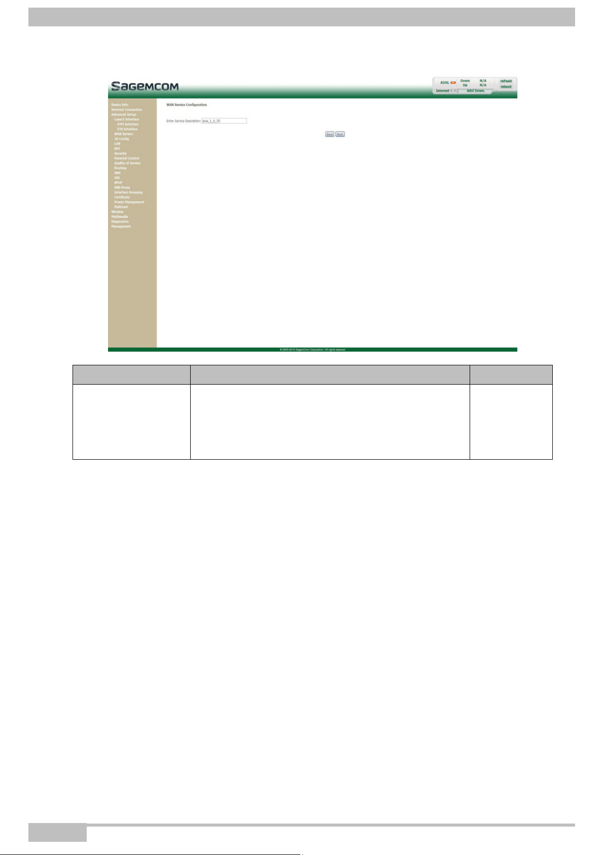
5- Information / Configuration
5.7.2.6 IP over ATM (IPoA)
Field Action Default value
Enter Service
Description
Displays the name of the service being configured. This
name, which is allocated automatically, is made up as
follows: Protocol_VPI_Index_VCI
For example: ipoa_1_0_35.
Note: You may enter another service name.
ipoa_1_0_35
Page 5-42 F@ST 4310 Reference Manual
Sagemcom Broadband SAS document. Reproduction and disclosure prohibited
Page 75

• Click on the Next button to continue configuring the WAN service.
5- Information / Configuration
Field Action
Default
value
WAN IP Address Enter the static IP address. 0.0.0.0
WAN Subnet Mask Enter a subnet mask. 0.0.0.0
F@ST 4310 Reference Manual Page 5-43
Sagemcom Broadband SAS document. Reproduction and disclosure prohibited
Page 76

5- Information / Configuration
• Click on the Next button to continue configuring the remote network (WAN) in IPoA mode.
Field Action Default value
Check the box to activate the NAT function.
Not checked
Note: NAT is a configurable IP address
Enable NAT
translation function which will be applied
to the interfaces of your router which you
will have activated for this function.
Enable Fullcone NAT
Check the box to activate the Fullcone NAT
a
function.
Not checked
Enable Firewall Check the box to activate the Firewall service. Not checked
Enable IGMP Multicast Check the box to activate the IGMP function. Not checked
a. This field only appears when the "Enable NAT" field is activated (box checked).
• Click on the Next button to continue configuring the remote network (WAN) in IPoA mode.
Page 5-44 F@ST 4310 Reference Manual
Sagemcom Broadband SAS document. Reproduction and disclosure prohibited
Page 77

• Select a preferred WAN interface as the system default gateway.
5- Information / Configuration
• Click on the Next button to continue configuring the remote network (WAN) in IPoA mode.
Field Action
Selected DNS Server
Interfaces
For more details, a summary table is presented below
for each column.
Available WAN
Interfaces
Primary DNS server Enter the primary DNS server
Secondary DNS server Enter the primary DNS server
F@ST 4310 Reference Manual Page 5-45
Sagemcom Broadband SAS document. Reproduction and disclosure prohibited
Page 78

5- Information / Configuration
Select DNS Server Interface from available WAN interfaces
Button Action
Transfer the interfaces selected in the Available WAN
• Click on the Next button to continue configuring the remote network (WAN) in IPoA mode.
Interfaces area to the Selected DNS Server Interfaces area.
Transfer the interfaces selected in the Selected DNS Server
Interfaces area to the Available WAN Interfaces area.
Field Description
Connection Type Displays the "IPoA" protocol.
NAT Displays the status of the NAT.
Firewall Displays the status of the firewall.
IGMP Multicast Displays the status of the IGMP function.
Quality of Service Displays the status of the Quality of Service function.
• Click on the Apply/Save button to confirm the new WAN service.
Page 5-46 F@ST 4310 Reference Manual
Sagemcom Broadband SAS document. Reproduction and disclosure prohibited
Page 79

5- Information / Configuration
5.7.3 3G Config
Object: This menu lets you configure 3G backup support to use a 3G USB modem that connected to the
USB interface of the router as a backup of ADSL Internet connection.
• In the Advanced Setup menu, select 3G Config.
The following screen opens:
Field Action Default value
Check the box to enable 3G backup. This backup will make the
Enable
PIN Enter the PIN number. -
APN
User Enter the user name. -
Password Enter the 3G USB modem password. -
Dial Number Enter the dial number of the 3G USB modem. -
Auth Protocol
• Click on the Save button to save the defined parameters.
Note
router connect to the 3G USB modem automatically when
ADSL line is broken.
Enter the APN (Access Point Name) protocol which allows your
Box to access the Internet.
Select the protocol to use in the scrolling down list:
• AUTO AUTH
• PAP (Password Authentification Protocol)
• CHAP (Challenge Handshake Authentification Protocol)
Disabled
AUTO AUTH
-
The router needs to be rebooted to take the parameters into account.
F@ST 4310 Reference Manual Page 5-47
Sagemcom Broadband SAS document. Reproduction and disclosure prohibited
Page 80

5- Information / Configuration
5.7.4 LAN
Object: This is used to configure the IP parameters for the local network (LAN).
• In the Advanced Setup menu, select LAN.
The following screen opens:
Field Action Default value
Groupname Select the required group. Default
IP Address Enter the address of your local network. 192.168.1.1
Subnet Mask Enter your network's subnet mask. 255.255.255.0
Enable IGMP
Snooping
Check this box to activate the IGMP (Internet Group
Management Protocol) protocol. This lets you manage the
declarations of belonging to one or more groups with Multicast
Not checked
routers.
Standard Mode
Blocking Mode
a
a.
Enable LAN side
Check the box if you wish the IGMP snooping runs in normal
mode (transparency with IGMP frames).
Check the box if you wish the IGMP snooping runs in blocking
mode (interception and removal of IGMP frames).
Check the box to activate the LAN side firewall. Not checked
Checked
Not checked
firewall
Disable DHCP
Server
Check this box to deactivate your router's DHCP server.
Note: You must configure your computer with the parameters
appropriate to your local network (IP address, subnet
mask and default gateway) as well as enter the primary
Not checked
and secondary DNS server addresses.
Page 5-48 F@ST 4310 Reference Manual
Sagemcom Broadband SAS document. Reproduction and disclosure prohibited
Page 81

5- Information / Configuration
Field Action Default value
Enable DHCP
Check this box to activate your router's DHCP server.
Note: You must configure your computer as DHCP client and
DNS client (or enter the primary and secondary DNS
Checked
server addresses).
Start IP Address Enter the first address attributed by your router's DHCP server. 192.168.1.2
End IP Address Enter the last address attributed by your router's DHCP server. 192.168.1.254
Leased Time (hour)
Static IP Lease List
Configure the
second IP Address
Enter an unavailability time (in hours) for each attributed
address.
Enter if required the list of static IP Lease.
Note: A maximum of 32 entries can be configured.
Check the box to configure the IP parameters (IP address,
subnet mask) of a second address for the local network (LAN).
24
-
Not checked
and Subnet Mask for
LAN interface
IP Address
Subnet Mask
a. These fields only appear when the "Enable IGMP Snooping" field is activated (box checked).
b. These fields only appear when the "Configure the second IP Address and Subnet Mask for LAN interface"
field is activated (box checked).
b
b.
Enter a second address for your local network (LAN). -
Enter a subnet mask for the second address for your local
network (LAN).
-
F@ST 4310 Reference Manual Page 5-49
Sagemcom Broadband SAS document. Reproduction and disclosure prohibited
Page 82

5- Information / Configuration
5.7.5 NAT
Object: NAT is a configurable IP address translation function which is applied to the interfaces of your
router which you have activated for this function.
Several translation function configurations and the NAT actions can be configured and may be
activated as indicated in section 5.7.5.1 > Add.
This section contains the following menus:
• Virtual Servers (see subsection 5.7.5.1)
• Port Triggering (see subsection 5.7.5.2)
• DMZ Host (see subsection 5.7.5.3)
5.7.5.1 Virtual Servers
Object: This menu is used to route directly to the External Ports the incoming data from a Service server
(such as, for example, FTP Server, SNMP, TFTP etc.) of the remote network (WAN) to computers
on the local network (LAN) via the Internal Ports.
• In the Advanced Setup menu, select NAT then select Virtual Servers.
The following screen opens:
Field Meaning
• Select a Service: Service available over Internet (such as, for
Server Name
External Port Start Internal start port (WAN side).
Page 5-50 F@ST 4310 Reference Manual
example FTP Server, SNMP, TFTP etc.).
• Custom Service: Name you want to allocate to a local server.
Sagemcom Broadband SAS document. Reproduction and disclosure prohibited
Page 83

5- Information / Configuration
Field Meaning
External Port End Internal end port (WAN side).
Protocol Transport protocol (TCP, UDP or TCP/UDP).
Internal Port Start Internal start port (LAN side).
This internal end port (LAN side) is associated with the external end port
Internal Port End
Server IP Address Computer address delivered by your router's DHCP server.
WAN Interface WAN interface used.
(WAN) side.
Note: This cannot be modified.
Remove
Check this box and click on the [Remove] button to remove the selected
object from the list.
Add
• Click on the Add button; the following screen appears:
F@ST 4310 Reference Manual Page 5-51
Sagemcom Broadband SAS document. Reproduction and disclosure prohibited
Page 84

5- Information / Configuration
Wi-Fi
Proceed as follows:
• Select the required WAN interface in the Use Interface list.
• Check the Select a Service box, then select the service of your choice from the scroll down list, for
example "SNMP".
The External Port Start, External Port End, Internal Port Start, Internal Port End and Protocol
fields (transport protocol associated with this service) are automatically filled in the table.
Note
You may complete the table by adding other ports associated with a protocol.
or
• Check the Custom Service box, enter the name of the server you want to connect to, then:
- Complete the ID Host of your computer's IP address (this is attributed by your router's DHCP
server).
- Fill in the External Port Start, External Port End, Internal Port Start, Internal Port End and
Protocol fields.
A few rules for entering values:
• When you want to select a single port, the start port (External Port Start or Internal Port Start) and the
end port (External Port End or Internal Port End) must be identical.
• When you want to select a range of ports, the start port number must be lower than the end port number.
• You must always start entering with the External Port Start and External Port End ports.
• When you allocate a number to an External Port Start, the same number is automatically allocated to
the Internal Port Start and identically for External Port End.
The following diagram contains an example:
The "Delta Force 2" service is available on your computer via the external ports 3568 and 3569 (WAN side)
and via the internal ports 3568 and 3569 (LAN side).
Page 5-52 F@ST 4310 Reference Manual
Sagemcom Broadband SAS document. Reproduction and disclosure prohibited
Page 85

5- Information / Configuration
5.7.5.2 Port Triggering
Object: The purpose of this menu is to open dynamically the firewall ports (open ports) via "Trigger Ports"
when an application (such as games or video) opens a connection via the transport layer (TCP or
UDP).
• In the Advanced Setup menu, select NAT then select Port Triggering.
The following screen opens:
Field Meaning
Application Name Application name.
• Protocol: Transport protocol (TCP, UDP or TCP/UDP).
Trigger
• Port Range: A port range contains a Start port and an End port.
Note: A single port is characterised by an identical start port and end port.
• Protocol: Transport protocol (TCP, UDP or TCP/UDP).
Open
• Port Range: A port range contains a Start port and an End port.
Note: A single port is characterised by an identical start port and end port.
WAN Interface WAN Interface used.
Remove
To remove an entry from the list, check the box and click on the [Remove]
button.
F@ST 4310 Reference Manual Page 5-53
Sagemcom Broadband SAS document. Reproduction and disclosure prohibited
Page 86

5- Information / Configuration
Add
• Click on the Add button; the following screen appears:
To configure Trigger Port and Open Port, proceed as follows:
• Select the required WAN interface in the Use Interface list.
• Check the Select an application box, then select the service of your choice from the scroll down list, for
example "Aim Talk".
The Trigger Port Start, Trigger Port End, Open Port Start, Open Port End and Protocol fields
(transport protocol associated with this service) are automatically filled in the table.
Note
You may complete the table by adding other ports associated with a protocol.
or
• Check the Custom application box to specify your own application, then:
- Enter the name of your own application.
- Fill in the Trigger Port Start, Trigger Port End, Open Port Start, Open Port End and Protocol
fields.
Page 5-54 F@ST 4310 Reference Manual
Sagemcom Broadband SAS document. Reproduction and disclosure prohibited
Page 87

5- Information / Configuration
Wi-Fi
Service Server
(Delta Force (client/server)
for example)
Start Open port : 3100
End Open port : 3999
Protocol : UDP
Start Open port : 3100
End Open port : 3999
Protocol : UDP
Start Trigger port : 3568
End Trigger port : 3568
Protocol : UDP
A few rules for entering values:
• When you want to select a single port, the start port (Trigger Port Start or Open Port Start) and the end
port (Trigger Port End or Open Port End) must be identical.
• When you want to select a range of ports, the start port number must be lower than the end port number.
The following diagram contains an example:
Using the "Trigger" 3568 port (WAN side), the "Delta Force" service server triggers the opening of port range
3100 to 3999 for your computer to access this service.
F@ST 4310 Reference Manual Page 5-55
Sagemcom Broadband SAS document. Reproduction and disclosure prohibited
Page 88

5- Information / Configuration
5.7.5.3 DMZ Host
Object: This "DMZ" (DeMilitarized Zone) lets you access the server you selected directly via the Internet
without going through the "Firewall".
Important
Caution, this process presents an intrusion risk. It is therefore vital that you take
precautions so that no connections may be initiated to the private network.
• In the Advanced Setup menu, select NAT then select DMZ Host.
The following screen opens:
Field Action
Enter the IP address of a server to activate the "DMZ" and
Default
value
-
therefore access it directly from the Internet.
DMZ Host IP
Address
To deactivate the "DMZ" zone, erase the address entered in the
field.
Note: Click on the Apply/Save button to take account of the
address or its erasure.
Note
The DMZ zone is deactivated by default.
Page 5-56 F@ST 4310 Reference Manual
Sagemcom Broadband SAS document. Reproduction and disclosure prohibited
Page 89

5- Information / Configuration
5.7.6 Security
5.7.6.1 IP Filtering
Outgoing
Object: This menu is used to create outgoing IP filters to refuse data from the LAN to the WAN and list the
existing outgoing IP filters.
By default, all the outgoing data is accepted.
• In the Advanced Setup menu, select Security > IP Filtering > Outgoing.
The following screen opens:
Field Meaning
Filter Name Name of the filter.
IP Version IP version used.
Protocol Transport protocol.
SrcIP/ PrefixLength
Source Port Source port.
DstIP/ PrefixLength
DstPort Destination port.
Remove
F@ST 4310 Reference Manual Page 5-57
Sagemcom Broadband SAS document. Reproduction and disclosure prohibited
"Source" address (your computer, for example) and
associated subnet mask.
"Destination" address (a machine on the Internet, for
example) and associated subnet mask.
Check the box and click on the [Remove] button to
remove the object from this list.
Page 90

5- Information / Configuration
Add
• Click on the Add button to display the following screen:
Field Action
Filter Name Enter a representative name for the filter.
IP Version
Protocol
Source IP
Select the dedicated IP version from the scroll down list (for example:
IPv4).
Select the dedicated protocol from the scroll down list (TCP/UDP, TCP,
UDP, ICMP).
Enter the Source IP address (LAN).
address[/prefix
length]
Source Subnet Mask Subnet Mask.
Source Port
(port or port:port)
Destination IP
Enter a "Source" port (LAN) or range of ports.
Note: For one port, for example, enter 80.
For a range of ports, enter 80:90.
Enter the Destination IP address (WAN).
address[/prefix
length]
Destination Port
(port or port:port)
Enter a "Destination" port (WAN) or range of ports.
Note: For one port, for example, enter 80.
For a range of ports, enter 80:90.
Page 5-58 F@ST 4310 Reference Manual
Sagemcom Broadband SAS document. Reproduction and disclosure prohibited
Page 91

5- Information / Configuration
Incoming
Object: This menu is used to create incoming IP filters to refuse data from the WAN to the LAN and list
the existing incoming IP filters.
By default, all the incoming data is refused when the Firewall is activated.
• In the Advanced Setup menu, select Security > IP Filtering > Incoming.
The following screen opens:
Add
• Click on the Add button to display the following screen:
F@ST 4310 Reference Manual Page 5-59
Sagemcom Broadband SAS document. Reproduction and disclosure prohibited
Page 92

5- Information / Configuration
Field Action
Filter Name Enter a representative name for the filter.
IP Version
Protocol
Source IP
address[/prefix
length]
Source Port
(port or port:port)
Destination IP
address[/prefix
length]
Destination Port
(port or port:port)
WAN interfaces
Select the dedicated IP version from the scroll down list (for
example: IPv4).
Select the dedicated protocol from the scroll down list (TCP/UDP,
TC P, U D P, IC M P ) .
Enter the Source IP address (WAN).
Enter a "Source" port (WAN) or range of ports.
Note: For one port, for example, enter 80.
For a range of ports, enter 80:90.
Enter the destination IP address (LAN).
Enter a "destination" port (LAN) or range of ports.
Note: For one port, for example, enter 80.
For a range of ports, enter 80:90.
Default
value
Checked
Select All
Field Action
Check the box to select all WAN interfaces.
Note: By unchecking the box, no interface is selected
and the other WLAN/LAN interfaces displayed
boxes become unchecked.
pppoe_0_8_32/ppp1 Check the box to select the displayed interface. Checked
br0/br0 Check the box to select the displayed interface. Checked
Page 5-60 F@ST 4310 Reference Manual
Sagemcom Broadband SAS document. Reproduction and disclosure prohibited
Page 93

5- Information / Configuration
5.7.7 Parental Control
Object: This menu is used to create and manage access time and Url restrictions for LAN devices which
are connected to the router.
This section contains the following menus:
• Time Restriction (see subsection 5.7.7.1)
• Url Filter (see subsection 5.7.7.2)
5.7.7.1 Time Restriction
Object: This menu is used to create and manage access time restriction for LAN devices which are
connected to the router.
• In the Advanced Setup menu, select Parental Control > Time Restriction.
The following screen opens:
F@ST 4310 Reference Manual Page 5-61
Sagemcom Broadband SAS document. Reproduction and disclosure prohibited
Page 94

5- Information / Configuration
Add
• Click on the Add button to display the following screen:
Field Action
User Name Enter a representative name for the LAN device.
Enter the MAC address of the required LAN device.
MAC Address
Note: To find out the MAC address of a Windows based PC,
open a command window and type "ipconfig /all".
Days of the week
Start Blocking Time
Select the days of the week on which the restriction is effective
by checking the corresponding box.
Enter the required blocking start hour (for example 08:00).
(hh:mm)
End Blocking Time
Enter the required blocking end hour (for example 20:00).
(hh:mm)
Page 5-62 F@ST 4310 Reference Manual
Sagemcom Broadband SAS document. Reproduction and disclosure prohibited
Page 95

5- Information / Configuration
5.7.7.2 Url Filter
Object: This menu is used to create and manage Url access restriction for LAN devices which are
connected to the router.
• In the Advanced Setup menu, select Parental Control > Url Filter.
The following screen opens:
Add
• Click on the Add button to display the following screen:
Field Action
URL Address Enter the Url address whose access must be restricted.
Enter the port number of the address which access must be
Port Number
restricted.
Note: 80 will be applied by default.
F@ST 4310 Reference Manual Page 5-63
Sagemcom Broadband SAS document. Reproduction and disclosure prohibited
Page 96

5- Information / Configuration
5.7.8 Quality of Service
This menu contains the following sub-menus:
• Queue Config (see subsection 5.7.8.1)
• QoS Classification (see subsection 5.7.8.2)
Object: This menu is used to allocate different types of traffic queues with different priorities in order to
improve the traffic flow. To do this, the quality of service (QoS) provides the following three
services: Classification (set-1, set-2), Marking (TOS, DSCP) and queues (Queuing).
The quality of service is only significant if all the traffic (data, video) is greater than the up rate of
the ADSL line.
• In the Advanced Setup menu, select Quality of Service.
The following screen opens:
Page 5-64 F@ST 4310 Reference Manual
Sagemcom Broadband SAS document. Reproduction and disclosure prohibited
Page 97

Field Action
5- Information / Configuration
Enable QoS
Select Default
DSCP Mark
Check the Enable QoS box to authorize QoS actions to be performed at the
ingress and egress interfaces.
The IP datagram DSCP (Differentiated Services Code Point, priority value from 0
to 63) identifies which output queue a packet is to be assigned to.
Default DSCP Mark is used to mark the priority of the packets when they are not
tagged in the computer. In this case the router will do it with the values indicated.
Select from the scroll down list:
• No Change (-1) : Value of -1 indicates no change from the incoming
packet,
• Auto Marking (-2)
• Default (000000) : Marks everything else to DSCP 0,
• AF13 (001110)
• AF12 (001100) : Recommended markings for Bulk-Data,
• AF11 (001010) : Recommended markings for Bulk-Data,
• CS1 (001000) : Recommended markings for Scavenger traffic,
• AF23 (010110)
• AF22 (010100) : Recommended markings for Transactional-Data,
• AF21 (010010) : Recommended markings for Transactional-Data,
• CS2 (010000) : Recommended markings for Network Management,
• AF33 (011110)
• AF32 (011100) : Recommended markings for Mission-Critical Data,
• AF31 (011010) : Recommended markings for Mission-Critical Data,
• CS3 (011000) : Call-Signalling markings,
• AF43 (100110)
• AF42 (100100) : Recommended markings for IP/VC,
• AF41 (100010) : Recommended markings for IP/VC,
• CS4 (100000) : Recommended markings for Streaming-Video,
• EF (101110) : IP Phones mark Voice to EF,
• CS5 (101000)
• CS6 (11000) : Routers mark Routing traffic to CS6,
• CS7 (111000)
Note: This drop-down list is present only if the box Enable Qos is checked.
F@ST 4310 Reference Manual Page 5-65
Sagemcom Broadband SAS document. Reproduction and disclosure prohibited
Page 98

5- Information / Configuration
5.7.8.1 Queue Config
Object: This menu is used to enable or disable QoS on an interface, and to configure QoS to use policy
maps attached to an interface.
• In the Advanced Setup menu, select Quality of Service then select QoS Queue.
The following screen opens:
Field State
Name Queue entry name
Key
Sequence number allocated by the system, incremented of a unit
to each addition of a QoS Queue.
Interface Name of the network interface configured (8/32 for example).
Scheduler Alg Scheduler algorithm allocated to this queue.
Precedence Priority allocated to "Queue Precedence" from 1 to 3.
DSL Latency
a
DSL Latency
PTM Priority PTM priority
QoS enabled or disabled for this interface.
Enable
Remove
a. This field appears only if the DSL mode selected is IPOA.
Page 5-66 F@ST 4310 Reference Manual
Note: This status can be amended starting from this window.
Check the box and click on the [Remove] button to remove the
queue from this list.
Sagemcom Broadband SAS document. Reproduction and disclosure prohibited
Page 99

Add
• Click on the Add button to display the following screen:
5- Information / Configuration
Field Action
Name Enter a representative name.
Select from the scroll down list:
Enable
• Disable: To disable the QoS queue entry
• Enable: To enable the QoS queue entry
Select from the scroll down list:
Interface
• Blank
• 8/32: Interface name.
Select from the scroll down list:
• Blank
• 1: High priority for this queue,
Precedence
• 2: Medium priority for this queue,
• 3: Low priority for this queue.
Note: A high priority leads to low packet loss.
Queue Weight
a
[1-63]
DSL Latency
a
Enter the corresponding value of the queue weight.
Select the DSL latency from the scroll down list.
a. This field appears only if the DSL mode selected is IPOA.
F@ST 4310 Reference Manual Page 5-67
Sagemcom Broadband SAS document. Reproduction and disclosure prohibited
Page 100

5- Information / Configuration
5.7.8.2 QoS Classification
Object: This menu is used for the classification of packets into traffic classes, and for the enforcement of
policies using queuing.
• In the Advanced Setup menu, select Quality of Service then select QoS Classification.
The following screen opens:
Page 5-68 F@ST 4310 Reference Manual
Sagemcom Broadband SAS document. Reproduction and disclosure prohibited
 Loading...