

Page 1
F@ST PLUG 500 PREMIUM
USER GUIDE
Page 2

F@ST PLUG 500 PREMIUM
Dear customer,
You have just acquired a new generation Sagemcom PLC adapter (Power Line Communication) and thank you for placing your
confidence in us.
This device has been manufactured with the utmost care. If you should have difficulties in operating it, we recommend that you consult
this user manual.
This product follows a strategy of continuous development. We reserve the right to make changes without notice, modifications and
improvements to the products described in this user manual.
To operate the device safely and easily, please read carefully the paragraph “Recommendations and safety instructions”, page 3.
The CE label confirms that the product complies with the 1999/5/EC regulations of the European Union Parliament regarding
wireless systems and telecommunications.
The declaration of compliance may be looked up on the www.sagemcom.com website section «Support», or can be obtained from
the following address :
Copyright © Sagemcom Broadband SAS
All rights reserved
Sagemcom is a registered trademark.
Sagemcom Broadband SAS
250, route de l'Empereur
92848 Rueil-Malmaison Cedex - France
2
Page 3

F@ST PLUG 500 PREMIUM
Recommendations and safety instructions
This device is intended to be connected to the AC power line. For installation instructions, please refer to the installation section
of this guide.
The following precautions should be taken when using this product.
• Read all instructions including the safety leaflet before installing and operating this product.
• Follow all warnings and instructions marked on the product.
• Unplug the device from the wall outlet before cleaning. Use a damp cloth for cleaning.
• Do not use liquid cleaners or aerosol cleaners.
• Do not operate this product near water.
• This product should never be placed near or over a radiator or heat register.
• Do not use an extension cord between the device and the AC power source.
• Only a qualified technician should service this product. Opening or removing covers may result in exposure to dangerous
voltage points or other risks.
• Do not plug the device into a power strip or surge protector because these devices may consist of filter and impair signal.
• Avoid plugging the device right next to noisy sources such as cell phone charger, Halogen lamps, vacuum cleaner, etc. These
cases result in sub-optimal transmission speed.
• Unplug the device from the wall outlet and refer the product to qualified service personnel for the following conditions:
- If liquid has been spilled into the product
- If the product has been exposed to rain or water
- If the product does not operate normally when the operating instructions are followed
- If the product exhibits a distinct change in performance
3
Page 4

Contents
Recommendations and safety
instructions .............................. 3
F@ST PLUG 500 PREMIUM
Tips & Tricks .......................... 17
Quick install ........................................ 17
Using Other Powerline Devices ........... 19
Power Saving Mode ............................ 20
Improve the Transmission Capacity .... 21
Contents .................................. 4
Discover... ............................... 5
Box Content .......................................... 5
Applications .......................................... 6
Getting to Know the Adapter ................. 7
Set up a network... ................. 11
The role of the Security Button ............ 12
Forming a new HomePlug
AV logical network with 2 devices ....... 13
Joining an existing HomePlug
Troubleshooting .................................. 22
Environnement ....................... 23
Packaging ........................................... 23
The product ........................................ 23
Appendix ................................ 24
Specifications ..................................... 24
AV logical network .............................. 15
Leaving an AV logical network ............ 16
4
Page 5
F@ST PLUG 500 PREMIUM
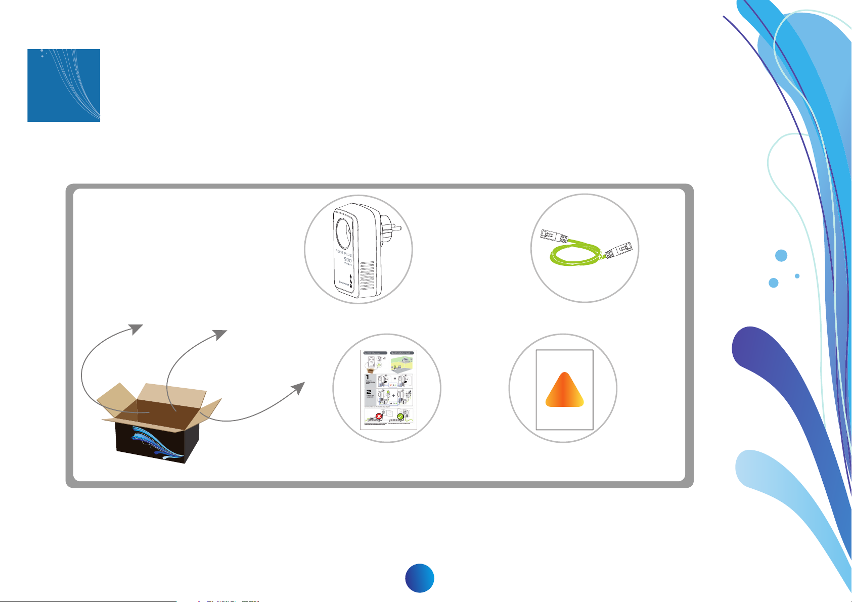
1
2 x -
F@ST PLUG 500 PREMIUM
2 x - RJ45 Ethernet cable
1 x - Quick Start guide
1 x - Safety Leaflet
!
Discover...
Box Content
5
Page 6
F@ST PLUG 500 PREMIUM
Room
Room
Room
Living-room
Hall
Apartment
Desktop
Set-Top-box / TV
IP Phone
Router
Game station
PC
Internet / Phone
Electrical circuit
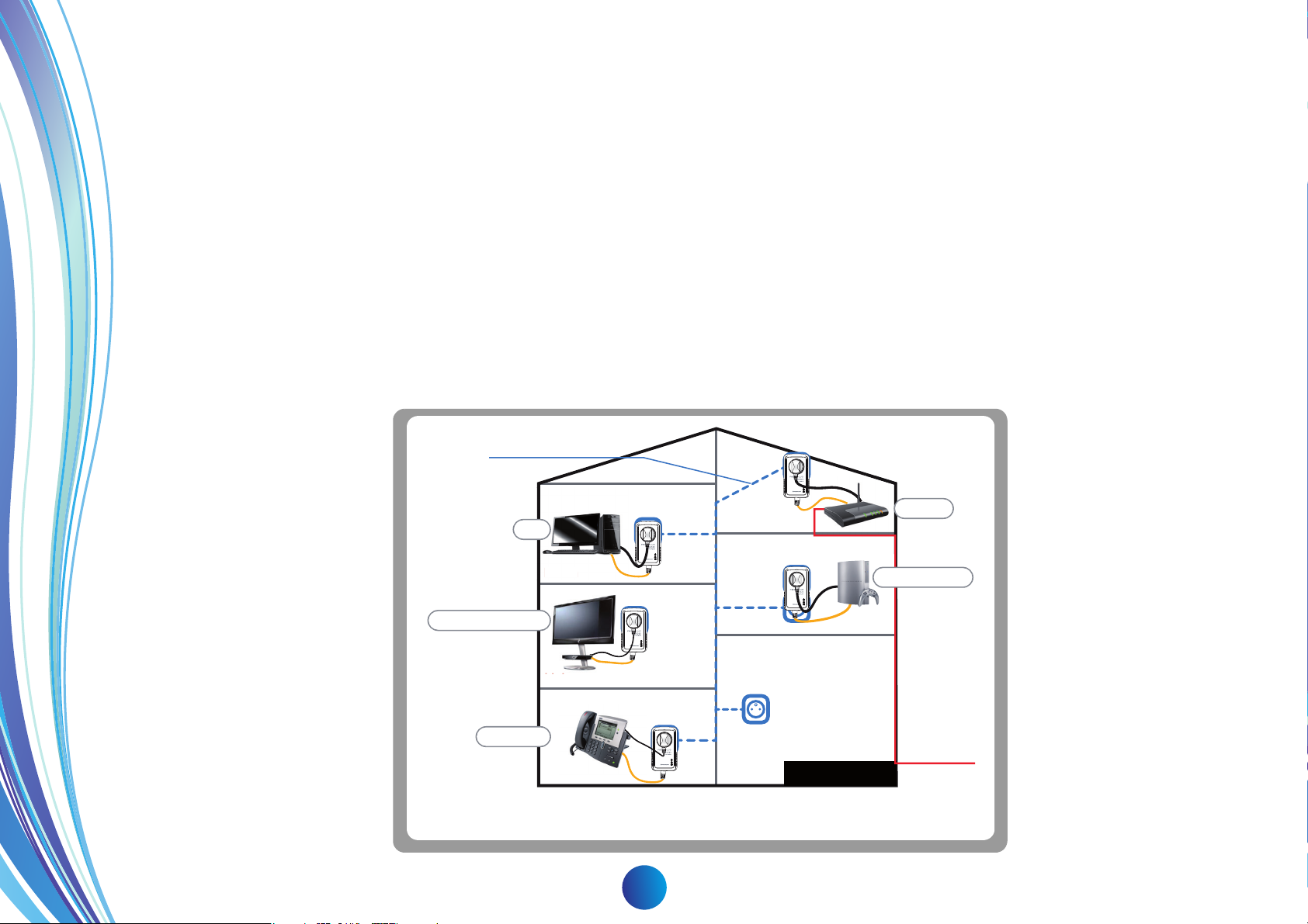
Applications
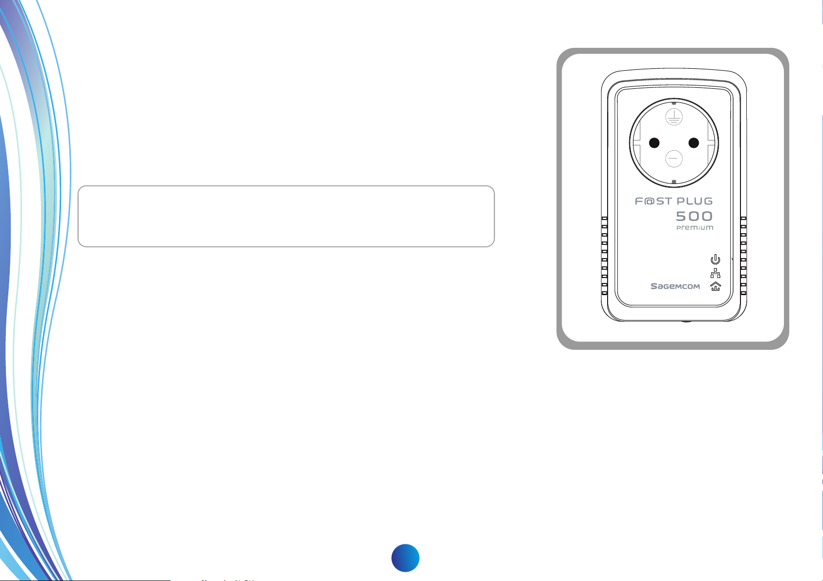
The F@ST PLUG 500 PREMIUM is a pass-through PLC adapter.
It relies on the household power line to transmit data over your Local Area Network (LAN).
It can be plugged directly into the power socket and therefore requires no additional wiring or special installation procedure. The device also
provides a female socket in which you can directly connect your equipment or a power strip, allowing you to save a socket space.
The F@ST PLUG 500 PREMIUM adapters are the ideal solution to help you establish a high-speed network that supports video, voice
and data without wiring and drilling.
They are suitable for a wide range of both residential (at home) and commercial (offices, apartments, hotels, warehouses…) network
applications.
The F@ST PLUG 500 PREMIUM adapters can reduce their consumption automatically by entering power save mode when they are not
in use.
6
Page 7
F@ST PLUG 500 PREMIUM
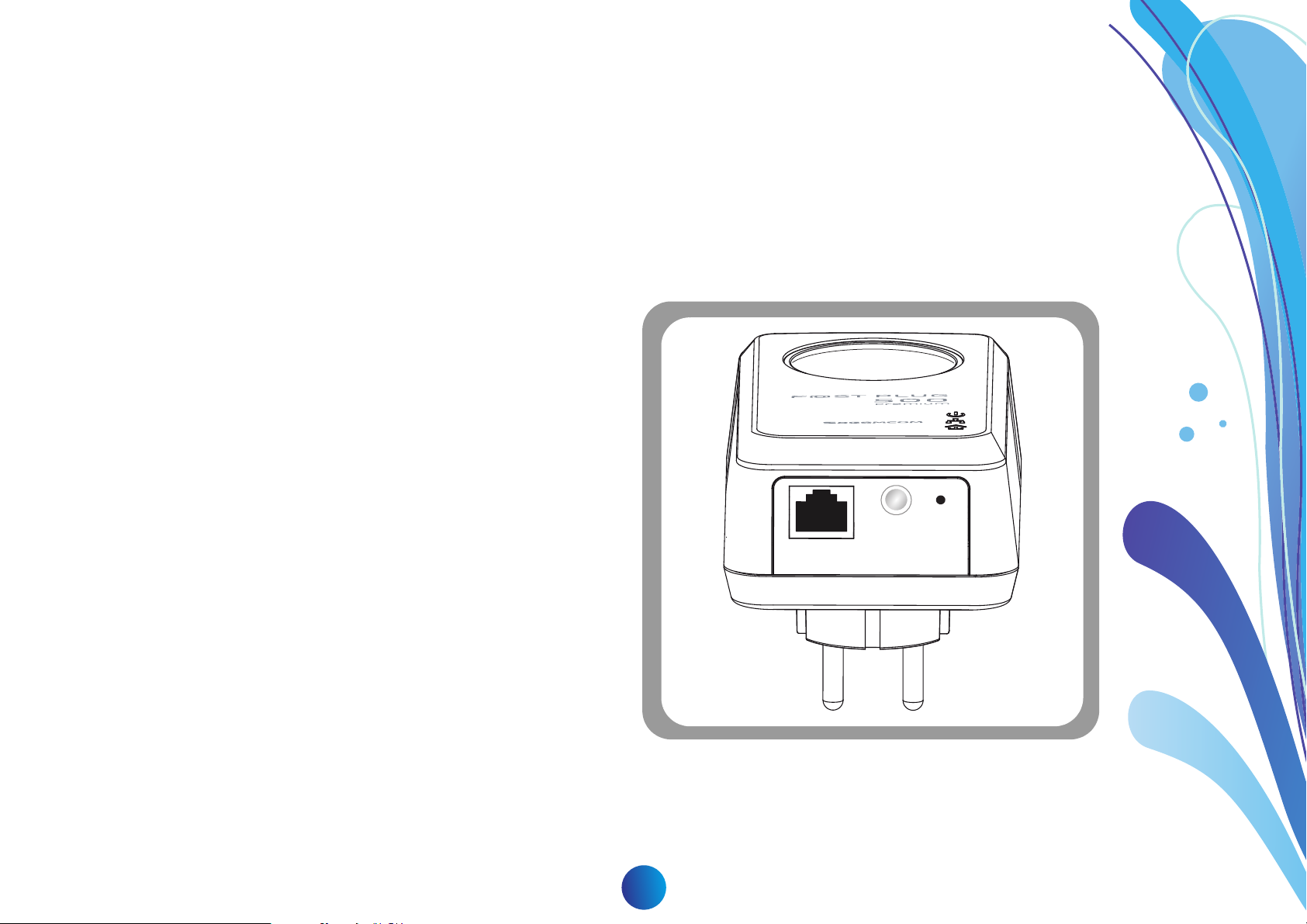
Getting to Know the Adapter
The Ethernet Interface
Ethernet: The Ethernet port connects to an Ethernet network cable. The other end of the cable connects to your computer or other
Ethernet-enabled network device.
The Adapter's Buttons
The following figure shows the adapter's buttons.
Security Button: To join or leave a HomePlug AV Logical
Network (AVLN).
• Pressing and holding the Security button for less than 2
seconds makes the adapter a member of the existing
AVLN (refer to the “Joining an existing HomePlug AV
logical network” section on page 15).
• Pressing and holding the Security button for more than 10
seconds randomizes the encryption keyword (refer to the
“Leaving an AV logical network” section on page 16).
Security
Reset
Reset: Restore the settings to the factory default.
7
Page 8
The Adapter's LEDs
Note The F@ST PLUG 500 PREMIUM devices will wake-up
automatically from the power saving mode when network activity
is detected.
All adapters' LEDs are located on the front panel.
There are 3 LEDs to indicate the adapter's status.
The following table describes the LEDs on the device.
F@ST PLUG 500 PREMIUM
16
~
250
8
Page 9
F@ST PLUG 500 PREMIUM
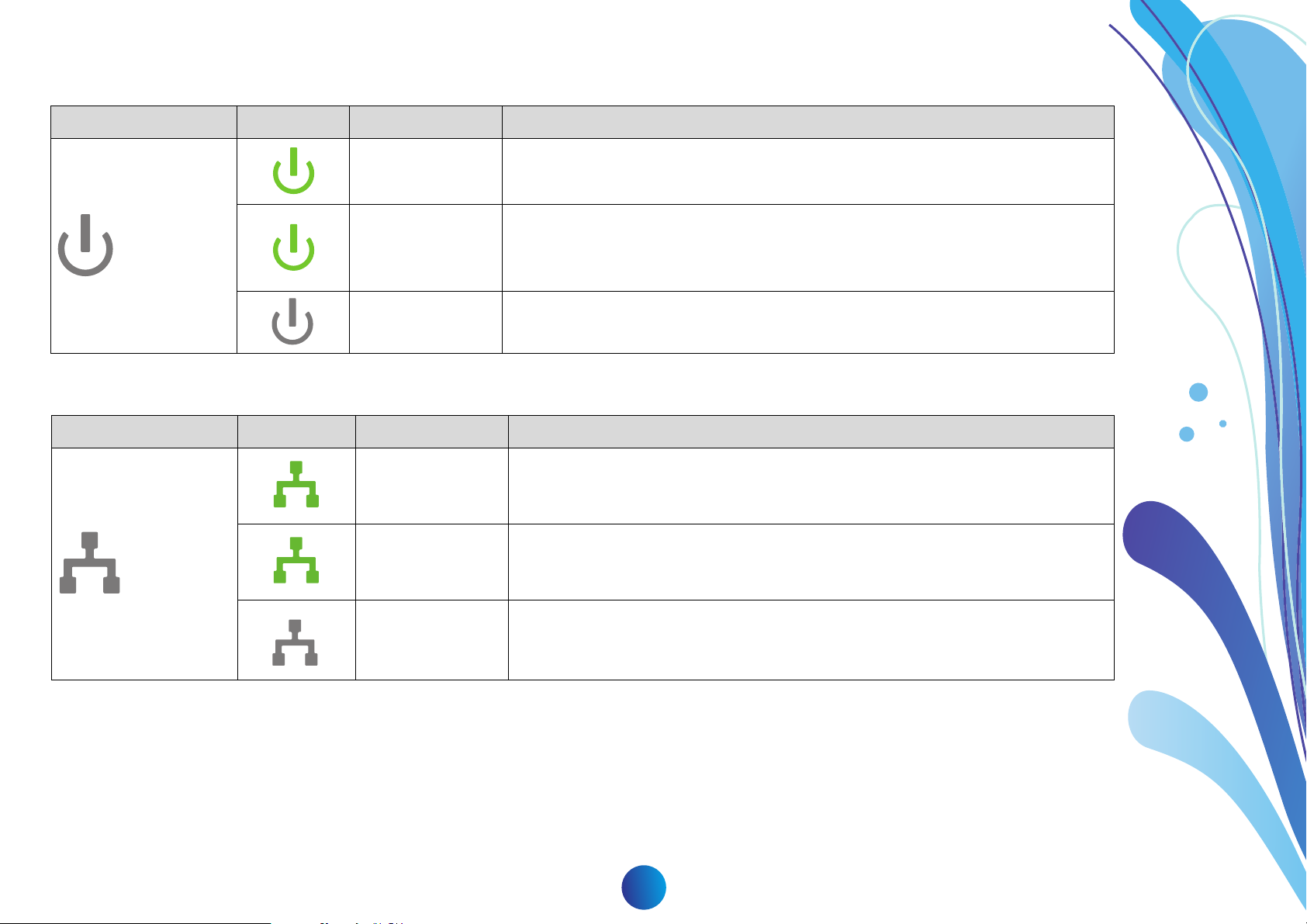
Power
LED Color Behavior Description
On System runs normally.
System enters the power saving mode (blinks every 15s) or,
Flashing
Off The PLC adapter is powered off.
System is resetting or,
System is in the process of password synchronization (blinks every 1s).
Ethernet
LED Color Behavior Description
On Ethernet connection has been established.
Flashing Data is being transmitted.
Off No Ethernet connection.
9
Page 10

Data
LED Color Behavior Description
F@ST PLUG 500 PREMIUM
Connection is suitable for full HD & 3D video streaming.
On
Flashing
Off
Connection is suitable for HD video streaming and online gaming
Connection is suitable for simple data transfer and Internet access.
When the device is scanning other PLC devices, the Data indicator blinks
quickly.
The PLC adapter is not connected to the power line network or is in
powersaving mode.
10
Page 11

F@ST PLUG 500 PREMIUM
2
Note F@ST PLUG 500 PREMIUM devices are shipped by pair and therefore have been already associated. These
devices will remember that they have been already paired together.
Therefore, if you do not already have PLC adapters in your home, both devices should connect automatically and no
additional steps are required.
However, it is strongly recommended to randomizes the encryption keyword of the devices and manually form a new
HomePlug AV logical network in order to secure it:
1 Plug the devices to the power line.
2 press the Security button of all devices more than 10 seconds untill all LEDs reset.
3 form a new HomePlug AV logical network (“Forming a new HomePlug AV logical network with 2 devices”, page 13).
Set up a network...
This section describes how to add new devices, or remove old devices from a power line network named HomPlug AV logical
network (AVLN).
Both actions can be accomplished by using the Security button.
Operation progress and outcome can be monitored by observing the behavior of the Power and Data LEDs.
11
Page 12

F@ST PLUG 500 PREMIUM
Important To be part of a power line network named HomPlug AV logical network, all devices must have the same keyword.
Only devices that are part the of the same AV logical network can communicate with each other.
Devices in power save mode cannot enter the pairing mode.
The Security button allows:
• When pressed less than 2 seconds, the adapter will enter pairing mode during 2 minutes. During this mode, the Power LED
will blink every second. While in pairing mode, the adapter will be able to pair with another device that is also in pairing mode.
• When pressed and held for more than 10 seconds it will randomize this encryption keyword. This will result in the considered
device being excluded from its current network until it can be paired again.
The role of the Security Button
Communications between F@ST PLUG 500 PREMIUM devices are encrypted with a 128 bit AES mechanism.
This encryption relies on a keyword which is identical for all F@ST PLUG 500 PREMIUM devices when leaving the factory.
12
Page 13

F@ST PLUG 500 PREMIUM
When two devices with different encryption keywords are connected to the same power line, proceed as follows to form a
HomePlug AV logical Network:
1 Plug HomePlug A to the power line.
2 Press the Security button for at least 1 second but less than 2 seconds to enter pairing mode on HomePlug A.
3 Plug the HomePlug B to the power line.
Security Reset
Forming a new HomePlug AV logical network with 2 devices
Device A
Room
B
Room
@
A
OfficeLiving room
1 2
<2 s <2 s
Device B
13
Page 14

F@ST PLUG 500 PREMIUM
4 Press the Security button for at least 1 second but less than 2 seconds to enter pairing mode on HomePlug B.
5 Wait for the pairing to complete.
During the pairing, the LED flashes red and switches to green when the device is paired.
If you encounter some difficulties, please refer to the “Troubleshooting” section on page 22.
Important Note :HomePlug B must be switched in pairing mode (Step 4) within 2 minutes after HomePlug A ist
switched in pairing mode(Step 2).
The pairing mode automaticaly stops after 2 minutes.
14
Page 15

F@ST PLUG 500 PREMIUM
In this scenario, there is an existing HomePlug AV logical network formed by devices A & B.
The two devices A and B are already plugged into the to the wall power socket and are not in power saving mode.
To add a new device HomePlug C to the existing network:
1 Plug the HomePlug C to the power socket.
2 Press the Security button for at least 1 second but less than 2 seconds to enter pairing mode on HomePlug C.
3 Press the Security button for at least 1 second but less than 2 seconds to enter pairing mode on HomePlug A or HomePlug B.
This must be done within 2 min after the previous step (Step 2).
4 During the pairing, the LED flashes red and switches to green when the device is paired.
if you encounter some difficulties, please refer to the “Troubleshooting” section on page 22.
Security Reset
Device A
Device B
B
A
@
OfficeLiving room
Room
Room
C
Device C
1
2
<2 s
<2 s
Important Note :HomePlug A or B must be switched in pairing mode (Step 3) within 2 minutes after HomePlug C ist
switched in pairing mode(Step 2).
The pairing mode automaticaly stops after 2 minutes.
Joining an existing HomePlug AV logical network
15
Page 16

Leaving an AV logical network
Assuming an AV logical network already exists and you want to remove one device from this network.
1 Simply press the Security button of the device you want to disconnect from the network (for instance device C) more than
10 seconds untill all LEDs reset.
2 Wait for reset to complete. The (Power), (Ethernet) and (Data) indicators blink when the device is powered
on.
At that moment, the Power and Ethernet indicators are green, and the Data indicator is orange.
Once the process completes, you may disconnect the device from the medium or join it to another logical network on the
same medium.
Security Reset
F@ST PLUG 500 PREMIUM
>10s
C
B
Device C
Room
Room
@
A
OfficeLiving room
Device A
Device B
16
Page 17

F@ST PLUG 500 PREMIUM
3
The purpose of this troubleshooting is to easily check if devices are properly
associated.
For a normal use, the devices should not be plugged directly in a multiple
socket power extension cord.
Please refer to recommendations on page 21.
1 To check the pairing of the devices, plug each device in a socket of the
multiple socket extension. The (Power), (Ethernet) and
(Data) indicators flash once when the device powers on.
2 The Data LED flashes red for few seconds and then turn
green .
Tips & Tricks
Quick install
Your F@ST PLUG 500 PREMIUM devices are shipped by pair and therefore have been already associated.
These devices will remember that they have been already paired together.
17
Page 18

F@ST PLUG 500 PREMIUM
If you are confused or if the LED blinks red for a long time or remains turned off while the power LED is on.
1 Press Reset button on the devices.
- OR -
2 Form a new AV logical network (refer to the “Forming a HomePlug AV logical network with 2 devices” section on page 21.).
In case of problem
18
Page 19

F@ST PLUG 500 PREMIUM
IMPORTANT Existing devices that are still using the default factory configuration, may associate automatically with the
F@ST PLUG 500 PREMIUM devices. You only have to plug device on the power network.
Using Other Powerline Devices
Compatibility & Coexistence
F@ST PLUG 500 PREMIUM devices are compatible with other HomePlug AV Powerline Devices (200 Mbps and 500 Mbps).
However, HomePlug 1.0 is not compatible with Homeplug AV. So F@ST PLUG 500 PREMIUM devices are not compatible with
older HomePlug 1.0 Powerline devices (85 mbps and 14 mbps).
Both HomePlug AV devices and HomePlug 1.0 can coexist on the same electrical network but they will not be able to communicate
with each other and therefore cannot associate into a single AV Logical Network (AVLN).
Creating a single HomePlug AV Logical Network with existing Powerline
Devices
If this is not the case, please proceed with the below indications :
You can create a single AV Logical network using existing HomePlug AV Powerline devices and F@ST PLUG 500 PREMIUM
devices.
But before doing so, you must ensure that each of your existing device is no longer part of a HomePlug AV logical Network.
Even if you only have a single existing device, it may have been part of another HomePlug AV Logical Network in the past.
• If your existing device(s) is (are) already F@ST PLUG 500 PREMIUM device(s) : Please read section 2 “Leaving an AV
logical network”, page 16 or perform a reset of the product.
• If your existing device(s) is (are) from another manufacturer, please refer to your devices's manufacturer documentation.
19
Page 20

F@ST PLUG 500 PREMIUM
IMPORTANT Plugging a new powerline device onto the network will not cause other devices on the same network to leave
their power saving mode.
However, here are a few suggestions that may, or may not apply to your situation:
- Some devices that have a security button but lack a reset button, may be reset or removed from their current AVLN by a long press
of the security button.
- The duration of the required long press may vary across manufacturers, it is often between 10 and 15 seconds.
- The use of a stopwatch is often recommended as not all devices display an event to indicate that the device has left the AVLN or
been reset.
- Some devices may have neither a security button nor a reset button; the use of a software utility provided by the manufacturer may
be required to alter the status of the existing devices.
- Once your existing devices have been removed from their HomePlug AV Logical Network or Reset, they can be associated to your
new F@ST PLUG 500 PREMIUM devices.
Please pefer to the section “Joining an existing HomePlug AV logical network”, page 15 for more details.
Power Saving Mode
F@ST PLUG 500 PREMIUM devices have a power saving feature.
When there is no activity on the Ethernet port (for instance Ethernet cable is unplugged) and devices are left idle for 2 minutes, they will
enter power saving mode.
All LEDs will turn off and the power LED will blink every 15 seconds.
In this mode, devices cannot be paired or reset.
To leave the power saving mode, device must be unplugged or network activity must resume on the Ethernet port.
20
Page 21

F@ST PLUG 500 PREMIUM
IMPORTANT It is important to follow the guidelines below in order to ensure optimal performance of your HomePlug AV
logical network.
Plug your equipement directly into the electrical socket integrated into the F@ST PLUG 500 PREMIUM as shown in
"Figure 1".
If you need extra power sockets, please ensure your multiple socket power extension cord is plugged directly into the device
as shown in "Figure 2".
Figure 1 Figure 2
Improve the Transmission Capacity
21
Page 22

F@ST PLUG 500 PREMIUM
Troubleshooting
Problem Reason Solution
Error occurs during pairing the devices.
The LED flashes Red for a
long time.
- OR -
New device has an other encryption key
Press Reset button on the device to add and pair
it again.
Power LED doesn’t blink
when activating pairing mode.
Ethernet LED is OFF.
Press on Security button is too short (< 1s).
Press on Security button is too long (> 2s).
Ethernet cable is disconnected or broken
the device connected to the HomePlug is
powered off.
Press Security button for 1 to 2 second.
Verify ethernet connection.
Try another Ethernet cable.
Ensure that the connected device is powered on.
22
Page 23

F@ST PLUG 500 PREMIUM
Environnement
Environmental protection and sustainable development is an important priority for Sagemcom.
Sagemcom has a policy of using environmentally- friendly systems and makes environmental protection an essential part of the life-cycle of its
products – from the manufacturing, to the installation, operation and disposal.
Packaging
The logo (green point) on the packaging means that a fee is paid to an authorised national organisation to improve packaging
recycling and the recycling infrastructure. Follow the local sorting regulations for this type of waste product in order to improve
recycling.
The product
The crossed out dustbin displayed on the product signifies that it belongs to the electrical and electronic equipment group. The
European regulations request you to carry out your own selective recycling collection at:
• the sales outlet when you buy a similar new device.
• the collection points available in your area (recycling centres, sorting points, etc).
This means you participate in the recycling and valorisation of used electric and electronic goods which would otherwise have a negative
impact on the environment and health.
23
Page 24

Appendix
Specifications
F@ST PLUG 500 PREMIUM
Chipset Intellon INT7400
Protocol HomePlug AV 1.1, IEEE1901
Co-exists with
existing HomePlug 1.0
PLC Rate 500Mbps
Modulation Band 2~68MHz
Modulation Schemes Supports1024/256/64/16/8-QAM,
QPSK, BPSK and ROBO
Encryption 128 AES
Outlet Current 220VAC 16A Maximum, 110VAC
20A Maximum
Filter characteristics -22 dB to -45 dB
LED’s Power
Ethernet: Ethernet link and
activity
Data: PLC link and activity
Push Button
Reset: Restore the factory
default settings
Security: Set the network
password automatically
Consumption 5W
Operating Temperature 0ºC to 45ºC
Storage Temperature -20ºC to 70ºC
Operating Humidity 10% to 90%, non-condensing
Storage Humidity 5% to 95%, non-condensing
Input Rating 100-240 VAC, 50/60Hz
Certifications CE, UL, FCC Part 15 Class B
Green Standard RoHS
Physical Dimension L×W×H: 122mm×70mm×41mm
Weight 256g
24
Page 25

F@ST PLUG 500 PREMIUM
Default CAP
The ‘Default CAP’ group allows for default priority mapping of packets that do not have a VLAN TAG. The settings are available for
Unicast (directed to a host).
• IGMP - (default CAP 3) - sets the channel access priority for IGMP frames - these are the group management frames, not the
stream data.
• Unicast - (default CAP 1) - sets the default channel access priority for unicast frames not matching any other classification or
mapping.
• IGMP managed Multicast Stream (Fixed to CAP 2) - sets the default channel access priority for stream data belonging to a
snooped IGMP multicast group.
• Multicast/Broadcast - sets the default CAP for multicast frames not in a snooped group and for broadcast frames.
VLAN Tag User Priority Default CAP Priority TOS Bit User Priority Default CAP Priority
0CAP10CAP1
1CAP01CAP0
2CAP02CAP0
3CAP13CAP1
4CAP24CAP2
5CAP25CAP2
6CAP36CAP3
7CAP37CAP3
25
Page 26

F@ST PLUG 500 PREMIUM
26
Page 27

All rights reserved. Sagemcom Broadband SAS reserves the right to change the technical characteristics of its products and services or to stop marketing
them at any time. The information and specications included are subject to change without prior notice. Sagemcom Broadband SAS tries to ensure that all
information in this document is correct, but does not accept liability for error or omission. No contractual document. All trademarks are registered by their
respective owners. Simplied joint stock company - Capital 35 703 000 € - 518 250 360 RCS Nanterre.
Sagemcom Broadband SAS
Headquarters: 250, route de l'Empereur
92848 Rueil-Malmaison Cedex - France
Tél. +33(0)1 57 61 10 00
Fax : +33(0)1 57 61 10 01
www.sagemcom.com
 Loading...