

Page 1

Triple Play Access Concentrator
SAGEM 3P@C
4450E
Next Generation DSLAM
SAGEM 3P@C
HARDWARE INSTALLATION MANUAL
Issue November 2004
S
3P@C Installation Manual
Page 0-0 Reproduction and communication in any form prohibited without the written permission of SAGEM SA
Page 2

Triple Play Access Concentrator
SAGEM 3P@C
4450E
Next Generation DSLAM
SAGEM 3P@C
HARDWARE INSTALLATION MANUAL
Issue November 2004
S
3P@C Installation Manual
Page 0-1 Reproduction and communication in any form prohibited without the written permission of SAGEM SA
Page 3

SAGEM 3P@C
WARNING
The information in this document covers a version of the system designated SAGEM 3P@C 4450E. It is subject to
technical changes.
The different versions of the manual will follow changes to the equipment.
3P@C Installation Manual
Page 0-2 Reproduction and communication in any form prohibited without the written permission of SAGEM SA
Page 4
SAGEM 3P@C
RECORD OF AMENDMENTS
(Each new edition supersedes the previous edition)
EDITION N° DATE PURPOSE OF UPDATES PAGES
1 November 2004 Creation of the document All pages
FOREWORD
You have just acquired a product which has been developed using the very latest
technologies and SAGEM
products.
SA know-how. SAGEM thanks you for your confidence in their
3P@C Installation Manual
Page 0-3 Reproduction and communication in any form prohibited without the written permission of SAGEM SA
Page 5

TABLE OF CONTENTS
Use Guide to This Manual 13
Part I 16
1. Overview of the 3P@C 4450E IP-DSLAM 1-1
1.1. S
YSTEM OVERVIEW 1-1
1.2. R
1.3. S
1.4. H
EPRESENTATIVE NETWORKING APPLICATIONS 1-1
YSTEM COMPOSITION 1-2
ARDWARE FEATURES 1-3
2. 3P@C 4450E Hardware Structure 2-1
2.1. S
HELF CONFIGURATION 2-1
2.1.1. Structure of the General Chassis 2-1
2.1.2. 10U Chassis 2-3
2.1.3. Fan Module 2-4
2.1.4. Air Deflector Frame 2-4
2.2. F
2.3. SMUB
ULL CONFIGURATION OF THE CABINET 2-6
AND SERVICE BOARDS 2-7
2.3.1. Service Processor Unit Board (SMUB) 2-7
2.3.2. VDSL Unit Board (VDUB) 2-10
2.3.3. ADSL Unit Board (ADUB) 2-11
2.3.4. ADSL Unit Card (ADUC) 2-13
2.4. P
OWER DISTRIBUTION SYSTEM 2-14
2.4.1. Overview 2-14
2.4.2. Functional Features 2-14
2.5. O
PTIONAL UPLINK INTERFACE MODULES 2-15
2.5.1. 1-port Gigabit Long-wave Optical Interface Module (DS-1GLX) 2-15
2.5.2. 1-port Gigabit Short-wave Optical Interface Module (DS-1GSX) 2-17
2.5.3. 2-port 100M Multi-mode Optical Interface Module (DS-2FMM) 2-18
2.5.4. 2-port 100M Single-mode Optical Interface Module (DS-2FSM) 2-19
2.5.5. 4-port 100M Electrical Interface Module (DS-4TXB) 2-21
2.5.6. VAS Card (DS-4ITX) 2-22
2.6. R
OUTE TRANSFER UNIT (RTU) 2-23
3. Installation Preparation 3-1
3.1. E
NVIRONMENTAL REQUIREMENTS 3-1
3.1.1. Temperature and Humidity Requirements 3-1
3.1.2. Cleanness Requirements 3-1
3.1.3. Floor Requirements 3-1
3P@C Installation Manual
Page 0-4 Reproduction and communication in any form prohibited without the written permission of SAGEM SA
Page 6

SAGEM 3P@C
3.1.4. Heat Dissipation Requirements 3-2
3.1.5. Power Supply Requirements 3-2
3.1.6. Grounding Requirements 3-2
3.1.7. Anti-interference Requirements 3-4
3.1.8. Other Requirements 3-4
3.2. S
AFETY REQUIREMENTS 3-5
3.2.1. Basic Safety Requirements 3-5
3.2.2. Antistatic Requirements 3-5
3.2.3. Avoiding Laser Damage 3-6
3.2.4. Lightning Protection Requirements 3-6
3.2.5. Anti-seismic Design Requirements 3-7
3.2.6. Fireproof Design Requirements 3-7
3.2.7. Precautions for Equipment Handling 3-7
3.3. I
3.4. P
NSTALLATION TOOLS AND MATERIALS 3-7
RODUCT CONFIGURATION LIST 3-8
3.4.1. Basic Configuration of the Product 3-8
3.4.2. Optional Components 3-8
3.5. U
NPACKING FOR ACCEPTANCE 3-9
3.5.1. Preparation 3-9
3.5.2. Unpacking 3-10
3.5.3. Goods Acceptance 3-14
4. Equipment Installation and Connection 4-1
4.1. C
ABINET INSTALLATION 4-1
4.1.1. Installation on the Cement Floor 4-2
4.1.2. Installation on the Antistatic Floor 4-8
4.1.3. Installing the Cabinet Guide Rails 4-14
4.2. I
NSTALLING THE EQUIPMENT 4-15
4.2.1. Installing the 10U Chassis 4-15
4.2.2. Installing the Fan Module 4-16
4.2.3. Installing the Air Deflector Frame 4-19
4.3. C
ONNECTING THE POWER AND GROUNDING CABLES 4-21
4.3.1. Connecting the Power Cables of the Equipment 4-21
4.3.2. Connecting the Power Cable of the Fans 4-22
4.3.3. Connecting the Grounding Cables 4-22
4.3.4. Equipment Power Supply Test 4-23
4.4. I
NSTALLING THE SERVICE PROCESSOR UNIT BOARD (SMUB) 4-23
4.4.1. Installing the Uplink Interface Modules 4-23
4.4.2. Installing the RTU 4-25
3P@C Installation Manual
Page 0-5 Reproduction and communication in any form prohibited without the written permission of SAGEM SA
Page 7

SAGEM 3P@C
4.4.3. Installing the SMUB 4-27
4.4.4. Connecting the Ethernet Interfaces of SMUB 4-28
4.4.5. Connecting the Optical Interfaces of SMUB 4-30
4.5. I
4.6. I
4.7. C
4.8. C
NSTALLING THE SUBSCRIBER SERVICE CARDS 4-31
NSTALLING THE DUMMY PANELS 4-31
ONNECTING THE SUBSCRIBER CABLES 4-32
ONNECTING THE CONSOLE CABLE 4-37
5. Suggestions to Ethernet Cabling 5-1
5.1. R
5.2. R
5.3. S
5.4. S
5.5. O
5.6. I
EQUIREMENTS FOR CABLE TYPES 5-1
EQUIREMENTS FOR CABLING LENGTH 5-1
PACING REQUIREMENTS FOR INDOOR CABLING 5-1
EVERAL FORBIDDEN OVERHEAD CABLING METHODS 5-3
THER REQUIREMENTS FOR OUTDOOR CABLING 5-4
NSTALLING EXTERNAL LIGHTNING ARRESTER 5-4
6. System Configuration and Management 6-1
6.1. E
6.2. S
QUIPMENT POWER-ON 6-1
ETTING UP THE CONFIGURATION ENVIRONMENT 6-1
6.2.1. Local Configuration via the Console Interface 6-1
6.2.2. Remote Configuration via Telnet 6-3
6.3. C
OMMAND LINE SYSTEM 6-4
6.3.1. Command Mode 6-4
6.3.2. Common Commands 6-4
6.3.3. Online Help of Command Line 6-5
6.3.4. Command Line Edit Feature 6-6
6.4. S
YSTEM MANAGEMENT 6-6
6.4.1. Storage Media and File Type 6-6
6.4.2. Program File Management 6-7
6.4.3. Configuration File Management 6-7
Part II 8
7. System Maintenance 7-1
7.1. S
YSTEM UPGRADE 7-1
7.1.1. Storage Media and File Type 7-1
7.1.2. Sequence of System Upgrade 7-1
7.1.3. Upgrading the System File 7-1
7.1.4. Upgrading the Master System Control Board 7-10
7.1.5. Upgrading the Standby System Control Board 7-12
7.2. M
ANAGING THE CONFIGURATION FILE 7-12
7.2.1. Type and Format of Configuration File 7-12
3P@C Installation Manual
Page 0-6 Reproduction and communication in any form prohibited without the written permission of SAGEM SA
Page 8

SAGEM 3P@C
7.2.2. Backuping the Configuration File 7-13
7.2.3. Loading the Configuration File 7-14
7.2.4. Erasing the Configuration File 7-14
7.3. Q
UERYING THE MAINTENANCE INFORMATION 7-14
7.3.1. Querying the Current Software Version 7-14
7.3.2. Viewing the Current Configuration 7-15
7.3.3. Querying the Port Status 7-15
7.3.4. Querying the VLAN Status 7-16
7.3.5. Viewing FIB Table 7-17
7.3.6. Viewing the ARP Table 7-17
7.3.7. Viewing the Route Information 7-18
7.3.8. Querying the System Running Time 7-18
7.4. H
ANDLING PASSWORD LOSS 7-18
8. Port Maintenance 8-1
8.1. C
8.2. C
HECKING THE OPTICAL INTERFACE 8-1
HECKING THE STATUS OF THE USER PORT 8-2
8.2.1. Querying the ADSL Port Status 8-2
8.2.2. Querying the VDSL Port Status 8-5
9. Card Maintenance 9-1
9.1. M
AINTENANCE FOR SYSTEM CONTROL BOARD 9-1
9.1.1. Check 9-1
9.1.2. Hot Plugging 9-2
9.1.3. Master/Standby Switchover 9-2
9.1.4. Reset 9-4
9.1.5. Replacing System Control Board 9-4
9.2. M
AINTENANCE FOR SERVICE BOARD 9-6
9.2.1. Check 9-6
9.2.2. Hot Plugging 9-7
9.2.3. Reset 9-8
9.2.4. Replacing Service Board 9-8
10. Power Distribution System Maintenance 1
10.1. C
HECKING AIR-BREAK SWITCH 1
11. Line Provisioning & Maintenance 11-1
11.1. M
AINTENANCE FOR AIR FILTER 11-1
11.1.1. Checking Air Filter 11-1
11.1.2. Cleaning and Replacing Air Filter 11-1
11.2. M
AINTENANCE FOR FAN SHELF 11-2
11.2.1. Checking Fan Shelf 11-2
3P@C Installation Manual
Page 0-7 Reproduction and communication in any form prohibited without the written permission of SAGEM SA
Page 9

SAGEM 3P@C
11.2.2. Replacing Fan Shelf 11-2
12. Line Commissioning and Maintenance 12-1
12.1. C
12.1.1. ADSL Technical Parameters 12-1
12.1.2. ADSL Line Commissioning 12-5
12.1.3. ADSL Line Maintenance 12-12
OMMISSIONING AND MAINTENANCE OF ADSL SUBSCRIBER LINE 12-1
12.2. C
OMMISSIONING AND MAINTENANCE OF THE VDSL SUBSCRIBER LINE 12-17
12.2.1. VDSL Technical Parameters 12-17
12.2.2. VDSL Line Commissioning 12-19
12.2.3. VDSL Line Maintenance 12-22
13. Fault Analysis and Solution 13-1
13.1. P
ROBLEM LOCATION & INFORMATION COLLECTION 13-1
13.1.1. General Check 13-1
13.1.2. Layer-2 Check 13-1
13.1.3. Layer-3 Check 13-2
13.1.4. Service Check 13-2
13.2. U
NSTABLE SERVICE DUE TO WRONG MAKING OF NETWORK CABLES 13-2
13.2.1. Common Causes 13-2
13.2.2. Processing Procedure 13-3
13.2.3. Typical Cases 13-3
14. Operation Instructions for the Auxiliary Devices 14-1
14.1. U
SE OF AC/DC CONVERTER 14-1
Appendix 14-1
LIST OF FIGURES
Figure 1-1 Triple Play services in Next Generation Networks .................................................................................. 1-1
Figure 2-1 General chassis of 3P@C 4450E ........................................................................................................... 2-1
Figure 2-2 Rear view of the general chassis of 3P@C 4450E ................................................................................. 2-2
Figure 2-3 Front view of the 10U chassis ................................................................................................................. 2-3
Figure 2-4 Slots for the SMUB and service boards .................................................................................................. 2-3
Figure 2-5 Front view of the fan module ................................................................................................................... 2-4
Figure 2-6 Outside view of the radiator fans............................................................................................................. 2-4
Figure 2-7 Sectional view of the air deflector frame ................................................................................................. 2-4
Figure 2-8 Heat dissipation of a single system ......................................................................................................... 2-5
Figure 2-9 Air ducts inside the cabinet ..................................................................................................................... 2-5
Figure 2-10 Full configuration of 3P@C 4450E........................................................................................................ 2-6
Figure 2-11 Slots of the SMUB ................................................................................................................................. 2-7
Figure 2-12 Front view of the SMUB ........................................................................................................................ 2-8
3P@C Installation Manual
Page 0-8 Reproduction and communication in any form prohibited without the written permission of SAGEM SA
Page 10

SAGEM 3P@C
Figure 2-13 Slots of the VDUB ............................................................................................................................... 2-10
Figure 2-14 Front view of the VDSL ....................................................................................................................... 2-10
Figure 2-15 Slots of the ADUB ............................................................................................................................... 2-12
Figure 2-16 Front view of the ADUB....................................................................................................................... 2-12
Figure 2-17 Slots of the ADUC ............................................................................................................................... 2-13
Figure 2-18 Front view of the ADUC....................................................................................................................... 2-13
Figure 2-19 Connection relations............................................................................................................................ 2-14
Figure 2-20 Front view of the DS-1GLX module .................................................................................................... 2-16
Figure 2-21 Front view of the DS-1GSX module .................................................................................................... 2-17
Figure 2-22 Front view of the DS-2FMM module ................................................................................................... 2-18
Figure 2-23 Front view of the DS-2FSM module .................................................................................................... 2-20
Figure 2-24 Front view of the DS-4TXB module..................................................................................................... 2-21
Figure 2-25 Front view of the DS-4ITX module ...................................................................................................... 2-22
Figure 3-1 Recommended power sockets ................................................................................................................ 3-3
Figure 3-2 Appearance of the packing box............................................................................................................. 3-10
Figure 3-3 Packing structure of the equipment inside the packing box.................................................................. 3-11
Figure 3-4 Appearance of the cabinet packing box ................................................................................................ 3-12
Figure 3-5 Draw out the packing box backward from the reverse direction ........................................................... 3-13
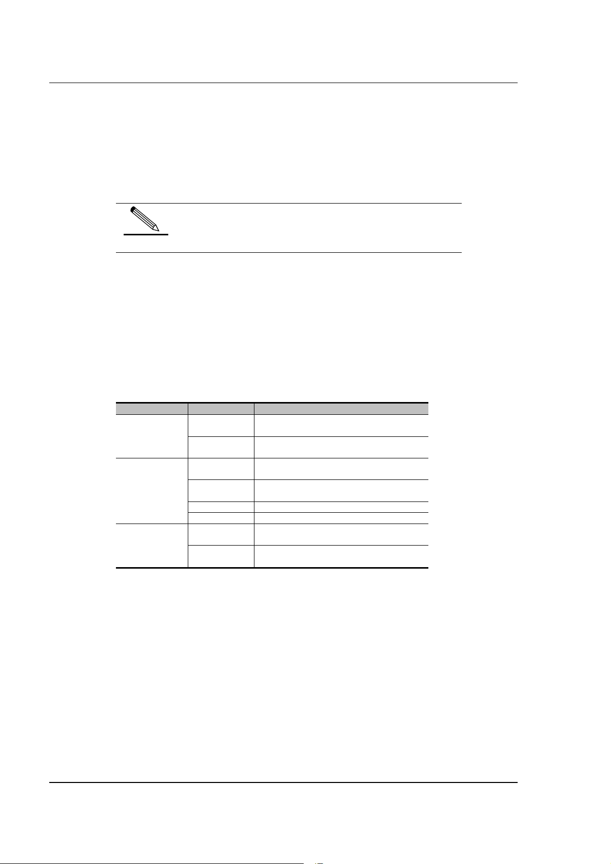
Figure 4-1 Cabinet installation flow chart ................................................................................................................. 4-1
Figure 4-2 Equipment installation space .................................................................................................................. 4-2
Figure 4-3 Flow of cabinet installation on the cement floor ...................................................................................... 4-3
Figure 4-4 Mounting hole positions for a single cabinet ........................................................................................... 4-4
Figure 4-5 Mounting hole positions for two cabinets ................................................................................................ 4-4
Figure 4-6 Installation sequence of the pressure plate assembly ............................................................................ 4-6
Figure 4-7 Completion of the installation of a single cabinet .................................................................................... 4-6
Figure 4-8 The connecting boards before combining two cabinets side by side...................................................... 4-7
Figure 4-9 The connecting boards after combining two cabinets side by side......................................................... 4-7
Figure 4-10 Effect after the installation of two combined cabinets ........................................................................... 4-7
Figure 4-11 Appearance of the A600 series support................................................................................................ 4-8
Figure 4-12 Completion of the installation of a single cabinet .................................................................................. 4-9
Figure 4-13 Flow of the cabinet installation on the antistatic floor............................................................................ 4-9
Figure 4-14 Cabinet marking template ................................................................................................................... 4-10
Figure 4-15 Connection positions of the mounting holes for the support and the antistatic floor .......................... 4-11
Figure 4-16 Assembly chart of the pressure plate assembly ................................................................................. 4-12
Figure 4-17 Positions of the bolts to be fastened ................................................................................................... 4-13
Figure 4-18 Completion of the installation of two combined cabinets .................................................................... 4-14
Figure 4-19 Guide rail ............................................................................................................................................. 4-15
Figure 4-20 Front view of the guide rails installed .................................................................................................. 4-15
3P@C Installation Manual
Page 0-9 Reproduction and communication in any form prohibited without the written permission of SAGEM SA
Page 11

SAGEM 3P@C
Figure 4-21 Fixing the hangers onto the 10U chassis............................................................................................ 4-16
Figure 4-22 Insert the 10U chassis into the rack and fix it ..................................................................................... 4-16
Figure 4-23 Install the fan supports ........................................................................................................................ 4-17
Figure 4-24 Install the fan module .......................................................................................................................... 4-17
Figure 4-25 Operate the puller adapter .................................................................................................................. 4-18
Figure 4-26 Install the air deflector frame ............................................................................................................... 4-19
Figure 4-27 Completion of the installation of a single general chassis .................................................................. 4-20
Figure 4-28 Installation of the -48V DC power cables ............................................................................................ 4-21
Figure 4-29 Power cable connection of the fans .................................................................................................... 4-22
Figure 4-30 Panel view of the SUMB...................................................................................................................... 4-23
Figure 4-31 Insert the pins of the uplink interface module into the socket of the SMUB........................................ 4-24
Figure 4-32 Fix the uplink interface module with screws........................................................................................ 4-25
Figure 4-33 Installation position of the RTU ........................................................................................................... 4-25
Figure 4-34 Insert the pins of the RTU into the socket of the SMUB ..................................................................... 4-26
Figure 4-35 Fix the RTU with screws...................................................................................................................... 4-26
Figure 4-36 Rear view of the RTU installed with screws and nuts ......................................................................... 4-27
Figure 4-37 Installation of the SMUB...................................................................................................................... 4-27
Figure 4-38 RJ-45 connector .................................................................................................................................. 4-28
Figure 4-39 Illustration of making a straight-through cable .................................................................................... 4-29
Figure 4-40 Illustration of making a crossover cable .............................................................................................. 4-29
Figure 4-41 Ethernet interface connection of the SMUB ........................................................................................ 4-30
Figure 4-42 SC optical connector ........................................................................................................................... 4-30
Figure 4-43 Uplink optical interface connection...................................................................................................... 4-31
Figure 4-44 Install a dummy panel ......................................................................................................................... 4-32
Figure 4-45 Installation of the LU and LC subscriber cables on the backplane ..................................................... 4-33
Figure 4-46 Pinouts of the LU subscriber cable ..................................................................................................... 4-33
Figure 4-47 Pinouts of the LC telephone line ......................................................................................................... 4-34
Figure 4-48 Cable bending and binding ................................................................................................................. 4-36
Figure 4-49 Single binding...................................................................................................................................... 4-37
Figure 4-50 Double binding .................................................................................................................................... 4-37
Figure 4-51 Console interface connection .............................................................................................................. 4-38
Figure 4-52 Input the connection name and select an icon for it............................................................................ 4-38
Figure 4-53 Select the connecting serial port ......................................................................................................... 4-39
Figure 4-54 Communication parameter setting ...................................................................................................... 4-39
Figure 4-55 Select the terminal emulation type ...................................................................................................... 4-40
Figure 5-1 Requirements for cabling length ............................................................................................................. 5-1
Figure 5-2 Parallel and crossed net spacing ............................................................................................................ 5-3
Figure 5-3 Direct overhead cabling between two buildings without any protection (1) ............................................ 5-3
3P@C Installation Manual
Page 0-10 Reproduction and communication in any form prohibited without the written permission of SAGEM SA
Page 12

SAGEM 3P@C
Figure 5-4 Direct overhead cabling between two buildings without any protection (2) ............................................ 5-3
Figure 5-5 Direct overhead cabling between two buildings without any protection (3) ............................................ 5-3
Figure 5-6 Direct overhead cabling from the outdoors of the top of a buildings to the bottom floor without any
protection ........................................................................................................................................................... 5-4
Figure 5-7 Connection of the external lightning arrester .......................................................................................... 5-4
Figure 6-1 Remote management of 3P@C 4450E via Telnet.................................................................................. 6-3
Figure 7-1 Connecting the console cables ............................................................................................................... 7-5
Figure 7-2 hoosing the file to be sent ....................................................................................................................... 7-8
Figure 7-3 File transfer interface............................................................................................................................... 7-8
Figure 7-4 Connection mode .................................................................................................................................... 7-9
Figure 11-1 Schematic diagram of pulled handle operation ................................................................................... 11-3
Figure 11-2 Installation of fan support .................................................................................................................... 11-4
Figure 11-3 Installation of fan module .................................................................................................................... 11-4
Figure 12-1 Frequency range of ADSL................................................................................................................... 12-1
Figure 12-2 The pass-band characteristics of the ADSL voice splitter................................................................... 12-2
Figure 12-3 ADSL distribution................................................................................................................................. 12-6
Figure 12-4 Connection of splitters......................................................................................................................... 12-9
Figure 12-5 VDSL frequency range ...................................................................................................................... 12-17
Figure 12-6 VDSL distribution............................................................................................................................... 12-19
Figure 12-7 Connection of splitters....................................................................................................................... 12-21
Figure 12-8 Networking diagram .......................................................................................................................... 12-24
LIST OF TABLES
Table 1-1 Boards, cards and uplink interface modules provided by 3P@C 4450E ................................................. 1-2
Table 1-2 Name, quantity and type of the interfaces supported by 3P@C 4450E................................................... 1-3
Table 1-3 Performance indexes of the 3P@C 4400
Table 2-1 General chassis composition of 3P@C 4450E ........................................................................................ 2-1
Table 2-2 Interface features of the SMUB ................................................................................................................ 2-8
Table 2-3 Type of uplink interface modules.............................................................................................................. 2-8
Table 2-4 Status definitions of the LED indicators on the SMUB ............................................................................. 2-9
Table 2-5 Status definitions of the LED indicators on the front panel of VDUB ..................................................... 2-11
Table 2-6 Status definitions of the LED indicators on the front panel of ADUB ..................................................... 2-12
Table 2-7Status definitions of the LED indicators on the front panel of ADUC ...................................................... 2-14
E
............................................................................................... 1-3
Table 2-8 Types of uplink interface modules .......................................................................................................... 2-15
Table 2-9 Status definitions of the LINK and ACT LEDs on the DS-1GLX module ............................................... 2-16
Table 2-10 Gigabit long-wave optical interface features of the DS-1GLX module ................................................. 2-16
Table 2-11 Status definitions of the LINK and ACT LEDs on the DS-1GSX module ............................................. 2-17
Table 2-12 Interface features of the DS-1GSX module.......................................................................................... 2-18
3P@C Installation Manual
Page 0-11 Reproduction and communication in any form prohibited without the written permission of SAGEM SA
Page 13

SAGEM 3P@C
Table 2-13 Status definitions of the LINK and ACT LEDs on the DS-2FMM module ............................................ 2-19
Table 2-14 Interface features of the DS-2FMM module ......................................................................................... 2-19
Table 2-15 Status definitions of the LINK and ACT LEDs on the DS-2FSM module ............................................. 2-20
Table 2-16 Interface features of the DS-2FSM module.......................................................................................... 2-20
Table 2-17 Status definitions of the LINK and ACT LEDs on the DS-4TXB module............................................. 2-21
Table 2-18 Interface features of the DS-4TXB module .......................................................................................... 2-21
Table 2-19 Status definitions of the LINK and ACT LEDs on the DS-4ITX module ............................................... 2-22
Table 2-20 Interface features of the DS-4ITX module............................................................................................ 2-23
Table 2-21 Structure of the RTU............................................................................................................................. 2-23
Table 4-1 Pinouts of the RJ-45 MDI interface ........................................................................................................ 4-28
Table 4-2 Pinouts of the RJ-45 MDIX interface ...................................................................................................... 4-28
Table 4-3 Pinouts of the LU subscriber cable......................................................................................................... 4-33
Table 4-4 Pinouts of the LC telephone line ............................................................................................................ 4-35
Table 5-1 Requirements of spacing between Ethernet cables and cables of other electric devices ....................... 5-2
Table 5-2 Requirements of spacing between the Ethernet cables on the wall and other pipelines ......................... 5-2
Table 6-1 Description of the read-only mode and the configuration mode .............................................................. 6-4
Table 6-2 Commands in the read-only mode ........................................................................................................... 6-4
Table 6-3 Common commands in the configuration mode....................................................................................... 6-5
Table 6-4 Line edit commands in the command line ................................................................................................ 6-6
Table 6-5 Correspondence between file types and command line parameters of 3P@C 4450E............................ 6-6
Table 7-1 Bootrom command ................................................................................................................................... 7-3
Table 7-2 Upgrade submenu in the network port ..................................................................................................... 7-3
Table 7-3 Relevant parameters downloaded by the network port of system control board ..................................... 7-4
Table 9-1 Description of LED status of the system control board SMUB ................................................................. 9-1
Table 9-2 Description of the indicator of the VDUB service board ........................................................................... 9-6
Table 12-1 ADSL parameter setting table .............................................................................................................. 12-3
Table 12-2 ADSL subscriber line length attenuation table ..................................................................................... 12-4
Table 12-3 ADSL line attenuation per kilometer within different frequency bands................................................. 12-4
Table 12-4 ADSL line connection parameters ........................................................................................................ 12-6
Table 12-5 DC loop resistance for subscriber lines with different core diameters per kilometer ........................... 12-8
Table 12-6 Line test reference table ....................................................................................................................... 12-8
Table 12-7 ADSL service line reference table ...................................................................................................... 12-10
Table 12-8 Broadband service user information record table .............................................................................. 12-11
Table 12-9 ADSL setting parameters and connection parameter record table .................................................... 12-11
Table 12-10 The minimum SNR value for the rates (for reference) ..................................................................... 12-18
Table 12-11 DC resistance reference value of common lines.............................................................................. 12-20
Table 12-12 VDSL setting parameters and connection parameter record table .................................................. 12-22
3P@C Installation Manual
Page 0-12 Reproduction and communication in any form prohibited without the written permission of SAGEM SA
Page 14

SAGEM 3P@C
USE GUIDE TO THIS MANUAL
Target Readers
This manual is intended for system administrators responsible for the installation and maintenance of the 3P@C
4450E IP-DSLAM (“3P@C 4450E”). Readers should have the following knowledge:
Local Area Networks (LANs)
Ethernet Concepts
Ethernet Switching and Bridging Concepts
Routing Concepts
Simple Network Management Protocol (SNMP)
Contents
This manual describes the installation and maintenance of 3P@C 4450E, including its features, components,
component functions as well as equipment connections and maintenance.
It briefly describes some software configuration information. For a detailed description of the commands and
configuration operations, please refer to the 3P@C 4450E IP-DSLAM Software Configuration Manual and the
3P@C 4450E IP-DSLAM Command Reference.
The 3P@C 4450E IP DSLAM User Manual consists of three parts:
Part I
It introduces the structure, installation, connection and basic configuration of the 3P@C 4450E , specifically
including the following contents:
Chapter
Title
Contents
Chapter 1
Product Overview
Introduces the functions, features and system components of 3P@C 4450E
Chapter 2
Product Structure
Describes the integrated equipment structure of 3P@C 4450E as well as the components and functions of its parts or modules
Chapter 3
Installation Preparation
Describes the installation environment and safety requirements, installation tools, materials, product configuration and
unpacking inspection of 3P@C 4450E
I Hardware Installation
I I
Chapter 4
Equipment Installation and Connection
Describes the installation and cable connection of cabinets, chassis and modules of 3P@C 4450E
Chapter 5
Ethernet Cabling Suggestions
3P@C Installation Manual
Page 0-13 Reproduction and communication in any form prohibited without the written permission of SAGEM SA
Page 15

SAGEM 3P@C
Gives suggestions on the FE interface cabling in practical engineering
Chapter 6
System Configuration and Management
Introduces the setup of the configuration environment, the command line system and the management mode of the related
programs and files in the system
Part II
II Maintenance
IIII
It introduces the maintenance methods and related knowledge of he 3P@C 4450E , specifically including
the following contents:
Chapter
Title
Contents
Chapter 7
System Maintenance
Describes system upgrade, configuration file management, common maintenance information view and handling of password
loss
Chapter 8
Port Maintenance
Describes optical interface detection and subscriber port status check
Chapter 9
Card Maintenance
Describes the maintenance of SMUB and service boards such as VDUB/ADUB/ADUC
Chapter 10
Power Distribution System Maintenance
Describes the check and handling of air switches
Chapter 11
Accessories Maintenance
Describes the maintenance of dust filters and fan frames
Chapter 12
Line Provisioning & Maintenance
Describes the provisioning and maintenance of ADSL and VDSL lines
Chapter 13
Fault Analysis and Solution
Describes the fault location and information collection methods and the handling in the case of service interruption from time to
time due to incorrect making of the network cables
Chapter 14
Operation Instructions for the Auxiliary Devices
Describes the usage of the HD4825 DC/AC converter
3P@C Installation Manual
Page 0-14 Reproduction and communication in any form prohibited without the written permission of SAGEM SA
Page 16

SAGEM 3P@C
Appendix Common Troubleshooting & Relevant Knowledge
It introduces the common troubleshooting and related knowledge of he 3P@C 4450E , specifically
including the following contents:
Appendix A
Diagnosis of Common Faults
Lists some common faults of 3P@C 4450E and the possible causes and solutions
Appendix B
Glossary
Explains some terminologies involved in this manual
Appendix C
Fiber-related Knowledge
Gives the related knowledge about optical fibers
Conventions
Conventions for icons are listed as follows:
Icon
Description
Warning
Notifies users that improper operation may cause damage to human body or equipment, service disruption or data loss during
the process of installation and service configuration.
Note
This icon alerts users to some precautions.
prompt
This icon provides some text-related information and some guidance for users, and helps users understand the text better.
Technical Support
SAGEM establishes a complete hierarchical service system consisting of 3 levels, namely, the
headquarter, area and local technical support centers. It provides all-weather and full-time telephone
hotline services. Any time when users have problems on our product and network operation, feel free to
contact us by local service support hotlines. Visit www.sagem.com to find out the local service support
hotlines, to see the latest products and to download needed technical documents.
3P@C Installation Manual
Page 0-15 Reproduction and communication in any form prohibited without the written permission of SAGEM SA
Page 17

SAGEM 3P@C
PART I
Hardware Installation
I
I I
3P@C Installation Manual
Page 0-16 Reproduction and communication in any form prohibited without the written permission of SAGEM SA
Page 18

CHAPTER 1
1. Overview of the 3P@C 4450E IP-DSLAM
This chapter describes the typical networking models, features and performance indexes of the 3P@C 4400E.
1.1. System Overview
As the heart of Next Generation network architecture, SAGEM 3P@C 4450E and 4048E are high-performance
IP-DSLAM platforms that enable to deliver a wide variety of services such as broadband internet, voice over
packet, LAN to LAN connections, video multicast streaming, leased lines and VPN, on any subscriber line.
Thanks to their flexible, modular and scalable design, SAGEM 3P@C systems can provide all services simply by
the composition of relevant units in the same carrier-class platform.
NG-DSLAM
SAGEM 3P@C supports any combinations of ADSL, ADSL2/2+ or VDSL user interfaces in several types of
high-density configurations : mini-shelf and large shelves.
Thanks to its internal architecture, the SAGEM 3P@C is able to concentrate user streams and switch them to
several network interfaces, managing traffic parameters in order to guarantee QoS requirements. Subtending
interfaces can be used to create star and daisy-chain extensions, offering a high scalability in order to reach
remote users.
A wide variety of Fast Ethernet, Giga Ethernet, Packet over SDH and even ATM uplink interfaces allows the
connection to Next Generation IP and Ethernet networks. Enhanced video services can be delivered over
ADSL2+ or ADSL connections, such as TV broadcast, Video on Demand and Pay Per View, using SAGEM
3P@C multicast and IGMP capabilities. Connecting to ISP network, SAGEM 3P@C can support B-RAS features
such as PPP session processing, tunnelling and termination, user authentication, IP address management and
dynamic routing.
Management
SAGEM IONOS NMS management platform is designed for the provisionning, monitoring and supervision of the
whole SAGEM 3P@C product family. This powerful NMS allows network-wide visibility and provides userfriendly graphical features. In addition, IONOS NMS enhances operational efficiency with its powerful
client/server architecture.
Scalable range
SAGEM 3P@C is a complete range of access equipment, scaling from small sized configurations to large central
office nodes.
SAGEM 3P@C 4450E is dedicated to high density CO, connecting up to 448 DSL users per subrack, whereas
SAGEM 3P@C 4048E is designed for small CO or remote sites connecting up to 48 ADSL users.
The micro-DSLAM is targeted to specific applications, such as Multi-Tenant Unit (MTU) and remote area.
Thanks to its stackable design, up to 192 users can be connected as the need for broadband connections grows.
The 3P@C 4048E can be installed as a stand alone unit connected to a switched network or as an extension of
3P@C 4450E in subtending mode.
3P@C Installation Manual
Page 1-1 Reproduction and communication in any form prohibited without the written permission of SAGEM SA
Page 19

Page 20
SAGEM 3P@C
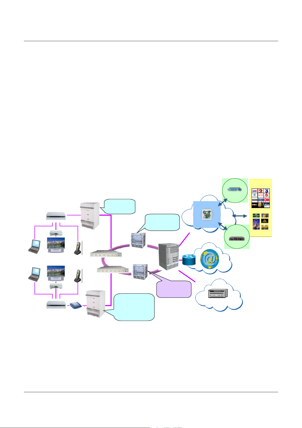
1.2. Representative Networking Applications
SAGEM is in a unique position to assist it’s customers with the design and implementation of next-generation
service offerings using Ethernet based broadband technology. SAGEM 3P@C solutions provide incumbent and
competitive carriers with Internet access, Voice over IP(VoIP), broadcast video(IPTV), Video on Demand (VoD),
Pay-Per-View, music channels and interactive television.
SAGEM 3P@C approach has shown reduced Cost of Ownership through Ethernet-based IP broadband
technology. Applying this technology to a solution customized for each customer can provide them with the
technological and competitive advantage needed for continued success in the broadband service market.
SAGEM 3P@C delivers an IP based broadband access solution that meets customer’s current needs as well as
their future needs for multi-service offerings. Our products are currently supporting all current service offerings
such as residential and commercial Internet access, Internet access through other ISPs, and LAN-to-LAN
connectivity.
SAGEM is able to build up Triple Play end to end solutions using F@st residential gateways and CPE, 3P@C
IP-DSLAM, GigaP@C MAN Ethernet switches or Ethernet over SDH equipment, and B-RAS, Video Streamers
and Voice Gateways and Softswitches.
RGW F @st 3202
STB
STB
RGW F @st 3190
3P@C 4400E
Giga P@C F 5610
GigaP@C F 5610
F@st 908
Mono-vc Multi-VLAN
3P@C 440 0E
Multicast I P
IGMP S nooping
Proxy
GigaP@C B6 805
MAN Ethernet
Ens ur e mu lt ic as t
service only to
authenticated users
Provide multicast
wire-speed
forwarding
IG MP Snoo ping
GigaP@C B6805
Mu lticas t IP
PIM Routing
Gi ga P@C B6 808
L2/L 3 switches
MPLS/VPLS
RIP/OSPF
Service Platform
Streaming Server
Internet
Soft Switch or VoIP Gateway
Live TV
Live Video
VoD
VOD Ser vers
Content
Providers
Liv e Cont e nt Pro vide rs
VO D C onten t
Provide rs
Figure 1-1 Triple Play services in Next Generation Networks
3P@C Installation Manual
Page 1-1 Reproduction and communication in any form prohibited without the written permission of SAGEM SA
Page 21

SAGEM 3P@C
1.3. System Composition
The 3P@C 4450E is composed of the following parts:
General chassis: It consists of a 10U chassis, a backplane, a fan module, a fan mounting
support and an air deflector frame.
Interface: Multiple uplink interfaces can be provided, including 100M electrical/optical
interfaces, gigabit optical interfaces and ATM interfaces.
Slots: Each 10U chassis provides 16 slots, where 2 are SMUB slots and 14 are service
board/card slots.
Power supply: The -48 V DC power supply is adopted. To connect to the 220 V AC power
supply, it is necessary to use the primary power supply system.
3P@C 4450E is installed in the 19-inch standard cabinet with the height of 2.2 m.
Based on the high-performance ASIC, 3P@C 4450E adopts modular structure design to provide abundant uplink
interface modules for your choice. See 1-1 for the specific module types. Each 3P@C 4450E consists of a 10U
chassis, a fan module, an air deflector frame and a fan frame support. Up to 16 boards/cards can be installed in
each 3P@C 4450E chassis. Among them, up to 2 SMUBs and 14 VDSL or ADSL service boards/cards can be
installed. Each SMUB can provide 2 gigabit optical interfaces/4 100M optical interfaces/8 100M electrical
interfaces/2 155M ATM interfaces. Each VDUB can provide 24 VDSL data interfaces, and the integrated
equipment supports up to 336 VDSL interfaces. Each ADUB can provide 32 ADSL interfaces, and the integrated
equipment supports up to 448 ADSL interfaces. See Table 1-2 for descriptions of the specific interface types.
You may select the appropriate boards, cards and uplink interface modules as required.
Table 1-1 Boards, cards and uplink interface modules provided by 3P@C 4450E
Module model Name of the card/uplink interface
module
SMUB Service processor unit board
VDUB VDSL service board
ADUB, ADUC ADSL unit board/card
RTU Route Transfer Unit
DS-1GLX 1-port gigabit long-wave single-mode
interface board
DS-1GSX 1-port gigabit short-wave multi-mode
interface board
DS-4TXB 4-port 100M interface board
DS-4ITX Value-added service card
DS-2FMM 2-port 100M multi-mode interface board
DS-2FSM 2-port 100M single-mode interface board
DS-A155SM 1-port 155M long-wave single-mode ATM
interface board
DS-A155MM 1-port 155M short-wave multi-mode ATM
interface board
3P@C Installation Manual
Page 1-2 Reproduction and communication in any form prohibited without the written permission of SAGEM SA
Page 22

Table 1-2 Name, quantity and type of the interfaces supported by 3P@C 4450E
SAGEM 3P@C
Interface name Quantity Interface
type
Gigabit optical interface (1000BaseSX/LX interface)
100M optical interface (100Base-FX
interface)
100M electrical interface
(10/100Base-TX interface)
ATM interface (155M single-/multimode ATM interface)
Console interface 1 × 2 RJ-45 Console
VDSL interface 24 × 14 European
ADSL interface 32 × 14 European
2 × 2 SC Uplink
4 × 2 SC Uplink
(8 + 1) × 2 RJ-45 Uplink
2 × 2 SC Uplink
connector
connector
Description
interface
interface
interface
interface
interface
Subscriber
interfaces
Subscriber
interfaces
For the detailed description of 3P@C 4450E structure,
please refer to Chapter 2.
prompt
1.4. Hardware Features
Table 1-3 lists the detailed performance indexes of the 3P@C 4450E.
Table 1-3 Performance indexes of the 3P@C 4400
Physical performance 3P@C 4450E
Dimensions of the 10U chassis
(Height × Width × Depth)
Dimensions of the fan module (Height
× Width × Depth)
Dimensions of the air deflector frame
(Height × Width × Depth)
17 kg when empty (containing a 10U chassis, a backplane, a fan module, a fan mounting
Weight
Working
environment
Power supply DC: -40.5V ~ -57V
Power consumption 1,200 W (1,200 W in full configuration mode)
support and an air deflector frame)
41 kg when fully populated (containing a 10U chassis, a backplane, a fan module, a fan
mounting support, an air deflector frame and 16 boards)
Temperature -5 °C ~ 50 °C
Humidity 5% ~ 95%, non-condensing
441.7 mm × 426.5 mm × 389.2 mm
44 mm × 434.6 mm × 360.1 mm
86.1 mm × 434.6 mm × 371.5 mm
E
3P@C Installation Manual
Page 1-3 Reproduction and communication in any form prohibited without the written permission of SAGEM SA
Page 23

SAGEM 3P@C
Physical performance 3P@C 4450E
Uplink ports 100M electrical and optical interfaces, gigabit optical interfaces
Port
configuration
Service ports VDSL and ADSL ports
Slot 16, among which, 2 SMUB slots and 14 service board/card slots
Hot plug Supported
Hot backup Redundancy hot backup for core partsError
tolerance
design
Negotiation function Full-duplex auto-negotiation
Basic
performance
Status
indication
Max. cable
length
Electromagnetic compatibility EMS feature: Complying with the standards of EN 55024 , ETSI
Security specifications Complying with the standards of EN 60950, UL 60950,
CPU
detection
Packet transfer rate
( L2/L3)
Forwarding mode Store-and-forwarding
Port status Communication status and LINK status
Universal status Power status, system status & hot-swap display
10/100Base-TX 100 meters Categories-3/4/5 shielded/unshielded twisted pairs
100Base-FX 62.5/125µm multi-mode fiber (max. 2km), 9µm single-mode fiber
1000Base-SX 62.5/125 µm multi-mode fiber (max. 275m), 50/125 µm multi-
1000Base-LX 9µm single-mode fiber (max.10km)
100Base-FX
interface
1000Base-SX
interface
1000Base-LX
interface
and ATM interfaces. All optical interfaces support single-mode
and multi-mode interface types, and the 100M optical interfaces
support the Trunk function
CPU detection
Wire speed
(max. 15km)
mode fiber (max. 550m)
EN 300 386, CISPR 24, GB/T 17626, GB/T 17618 and IEC
61000-4
CAN/CSA-C22.2 NO. 60950, GB 4943, IEC 60950, and AS/NZS
60950
SC
SC
SC
Interface type
DS-A155MM (155M
multi-mode ATM)
interface
DS-A155SM (155M
single-mode ATM)
interface
Console interface RJ-45
10/100Base-TX
interface
SC
SC
RJ-45
3P@C Installation Manual
Page 1-4 Reproduction and communication in any form prohibited without the written permission of SAGEM SA
This page intentionally left blank
Page 24

CHAPTER 2
2. 3P@C 4450E Hardware Structure
This chapter describes hardware structure of the 3P@C 4450E, including the whole-equipment
configurations and the description of each service module.
2.1. Shelf Configuration
2.1.1. Structure of the General Chassis
The general chassis of 3P@C 4450E is called 3P@C 4450E-IPDSLAM-10U general chassis kit. It
contains a 10U chassis, a backplane, a fan module, a fan mounting support and an air deflector frame.
Its outside view is shown in Figure 2-1.
Figure 2-1 General chassis of 3P@C 4450E
10U chassis
Fan module
Air deflector
frame
The general chassis composition of 3P@C 4450E is described in Table 2-1:
Table 2-1 General chassis composition of 3P@C 4450E
Name Height Composition Application
Slots 0 ~ 1 For SMUB10U chassis 10U
Slots 2 ~ 15 For ADUB, ADUC or VDUB
Fan
module
Air deflector
frame
1U 6 fans inside For system cooling
2U Slant spacer
inside
Air ducts (inlet from the front and
outlet from the rear)
3P@C Installation Manual
Page 2-1 Reproduction and communication in any form prohibited without the written permission of
SAGEM SA
Page 25
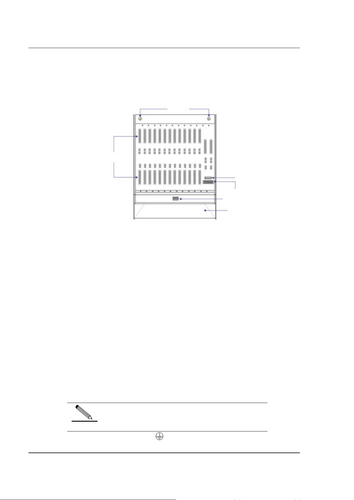
SAGEM 3P@C
3P@C 4450E provides the uplink interface and the Console port on the SMUB. The rest subscriber
line outlets are set on the backplane, that is, the rear leading-out mode is adopted. Therefore, all the
subscriber line interfaces and power supply interfaces are provided on the rear of 3P@C 4450E, as
shown in Figure 2-2:
Figure 2-2 Rear view of the general chassis of 3P@C 4450E
Grounding
socket
DIN
connector
Power interfac e
of the fans
Power interface of
the equipment
Power interface of
the fan module
Air outlet of the air
deflector frame
Viewed from the rear, the general chassis of 3P@C 4450E consists of the following parts:
DIN connector: Subscriber line interface
Equipment power supply interface: -48 V DC power supply interface
Fan power supply interface: Connects with the fan module power socket to supply
power to the fan
Fan module power socket: Connects with the fan power supply interface to supply
power to the fan
Grounding socket: Equipment grounding
Outlet of the air deflector frame: Hot air outlet of the switch below when multiple sets
of equipment are working
The DIN connectors are used for the subscriber line interfaces in two rows (upper and lower). Each
DSL service board needs 2 groups of subscriber lines. One group is the LU line that corresponds to
the connector in the upper row and is connected to the subscriber line, and the other group is the LC
line that corresponds to the connector in the lower row and is connected to the PSTN switch. The slots
correspond to the types of the service boards inserted in the chassis front to support subscribers of
different quantities. For the definition and connection method of subscriber lines, refer to the contents
in Section 4.7.
For ADUB/ADUC, each slot supports 32 subscribers.
For VDUB, each slot supports 24 subscribers.
The 3P@C 4450E rear also provides an equipment power supply interface, a fan power supply
interface and a fan module power supply socket.
Here the -48 V DC power supply is adopted for 3P@C
4450E.
prompt
In addition, two grounding sockets marked with are provided on the upper part of the rear panel for
equipment grounding.
3P@C Installation Manual
Page 2-2 Reproduction and communication in any form prohibited without the written permission of SAGEM SA
Page 26
SAGEM 3P@C
2.1.2.
2.1.2. 10U Chassis
2.1.2.2.1.2.
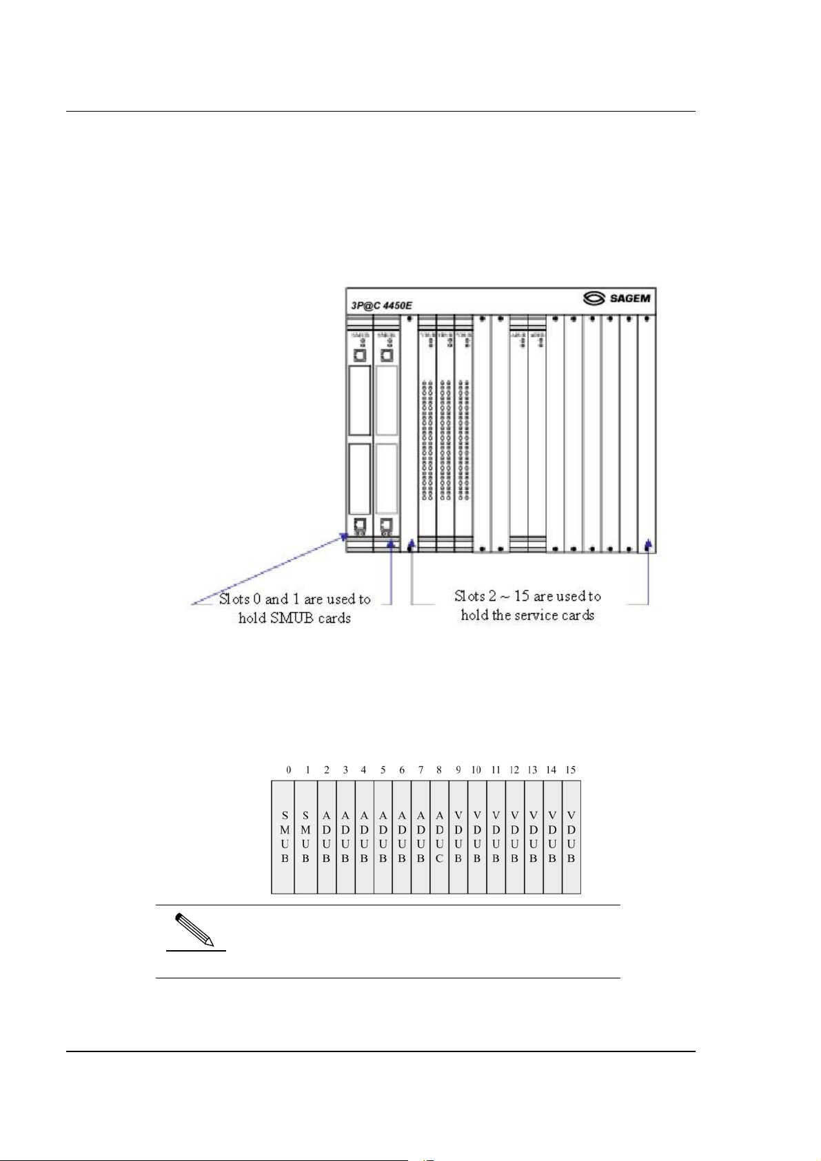
The 10U chassis is adopted for 3P@C 4450E. Altogether 2 SMUBs and 14 ADSL/VDSL service
boards can be installed at the same time, as shown in the following figure:
Figure 2-3 Front view of the 10U chassis
Each 10U chassis provides 16 slots which are numbered 0 ~ 15 from left to right. The former 2 slots
(slots 0 ~ 1) with a width of 1.4 inch each are used to insert the SMUBs. SMUBs can be inserted in
both slots at the same time, or only one SMUB is inserted either in slot 0 or in slot 1. The latter 14 slots
(slots 2 ~ 15) with a width of 1 inch and a depth of 340 mm each are used to insert VDUB or
ADUB/ADUC. Descriptions of the slots for the SMUB and the service boards are shown in Figure 2-4.
Figure 2-4 Slots for the SMUB and service boards
1. The service board slots support the interchange of VDSL
and ADSL service boards.
prompt
2. Please install dummy panels in the slots not inserted with
any boards.
3P@C Installation Manual
Page 2-3 Reproduction and communication in any form prohibited without the written permission of SAGEM SA
Page 27
SAGEM 3P@C
2.1.3.
2.1.3. Fan Module
2.1.3.2.1.3.
In the lower part of the 10U chassis is a 1U fan module, as shown in the following figure:
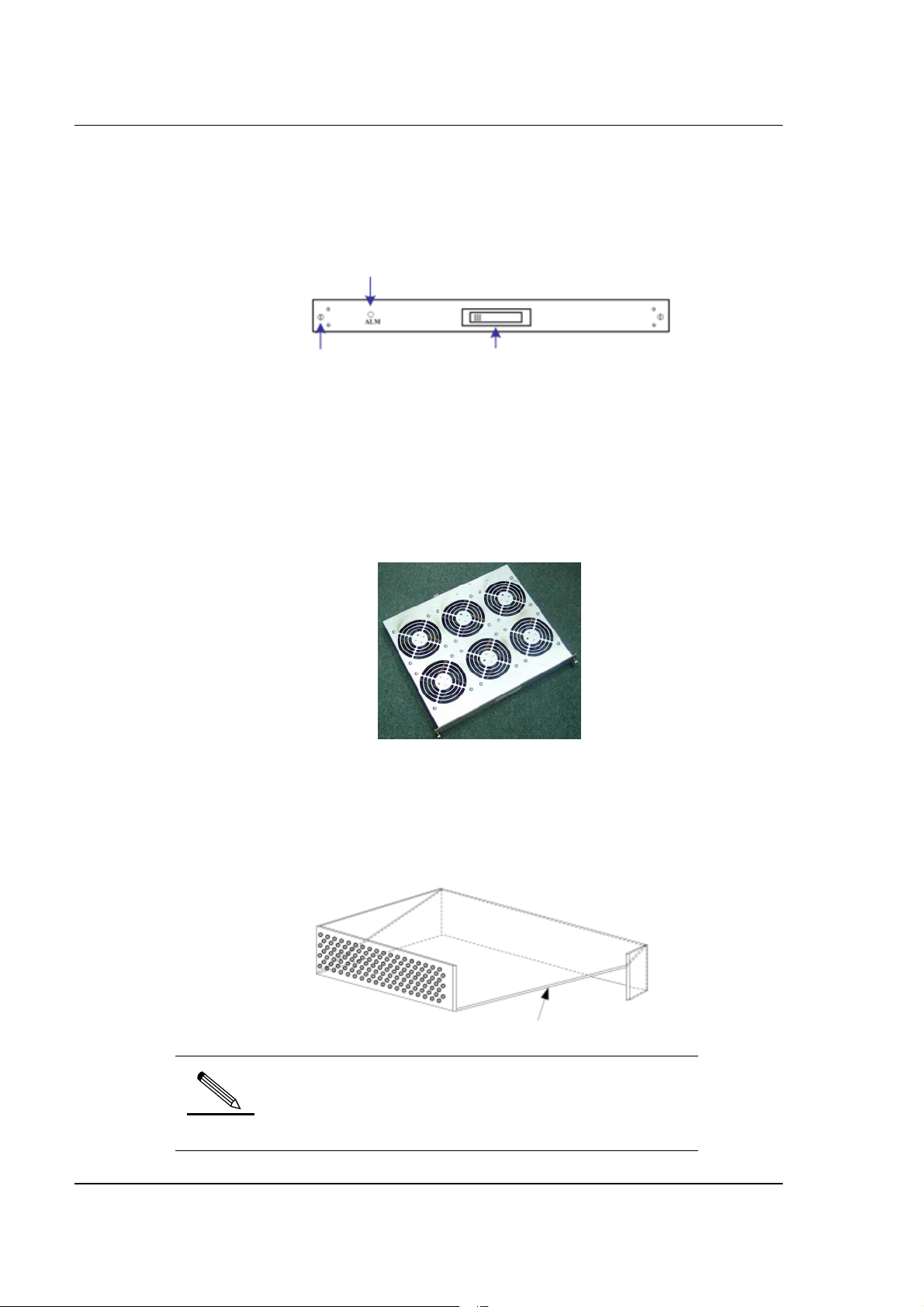
Figure 2-5 Front view of the fan module
Alarm LED
Screw Hidden puller adapter
Viewed from the front, the fan module consists of the following parts:
Screw: Used to fix the fan module.
Alarm indicator: Used for giving out failure alarm of the fan module
Hidden puller adapter: Usually closed. When removing the fan module, it can be
used to pull out the fan module. For the specific operations, refer to the related
contents in Section 4.2.2.
Each fan module provides 6 radiator fans, as shown in Figure 2-6:
Figure 2-6 Outside view of the radiator fans
2.1.4.
2.1.4. Air Deflector Frame
2.1.4.2.1.4.
Below the fan module is a 2U air deflector frame with the front inlet and rear outlet design and isolated
in the middle by a spacer. The sectional view of the air deflector frame is shown in the following figure:
Figure 2-7 Sectional view of the air deflector frame
Spacer
When the switch is operating, the cold air is drawn in above
the spacer. If multiple switches are operating at the same
time, the hot air coming out from the lower switch are
prompt
3P@C Installation Manual
Page 2-4 Reproduction and communication in any form prohibited without the written permission of SAGEM SA
exhausted below the spacer via the rear of the air deflector
frame.
Page 28
SAGEM 3P@C
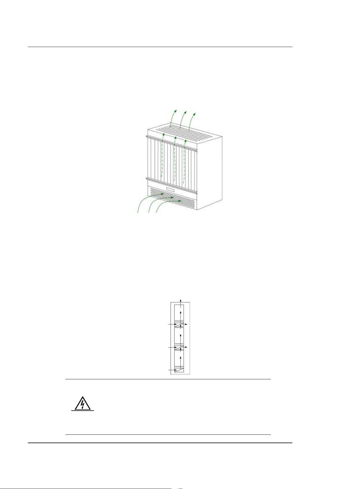
To satisfy the requirement for long-term equipment operating temperature, the general chassis design
of 3P@C 4450E fully considers the system heat dissipation. When a single device is operating, the
heat dissipation of the system is shown in Figure 2-8, where, the air is led in from the lower part and
led out from the upper part in the chassis front. The air outlet is on the top of the switch.
Figure 2-8 Heat dissipation of a single system
Hot air is discharged
Cold air comes in
On the air deflector frame is a fan module with 6 radiator fans built in. When the fans are started, the
cold air is drawn in from the inlet on the front of the air deflector frame, then goes upward in the
cabinet. It passes by the switch, and takes away the heat of the switch, and finally goes out from the
top of the switch.
When multiple switches operate at the same time, the hot air in the lower switch are let out from the
top of the switch, and exhausted via the rear outlet of the air deflector frame above it. The following
figure shows the air ducts in the cabinet in the case that multiple switches are operating at the same
time.
Figure 2-9 Air ducts inside the cabinet
The radiator fans are used for cooling and heat dissipation to
improve the temperature features of the system and ensure the
normal operation of the switch. Make sure these ventilation
holes are not blocked and enough space is reserved on two
Warning
sides of the equipment for air circulation, ventilation and heat
dissipation. Otherwise, if the components in the equipment are
overheated, the system would not work normally or even the
components would be damaged by overheat.
3P@C Installation Manual
Page 2-5 Reproduction and communication in any form prohibited without the written permission of SAGEM SA
Page 29
SAGEM 3P@C
2.2.
2.2. Full Configuration of the Cabinet
2.2.2.2.
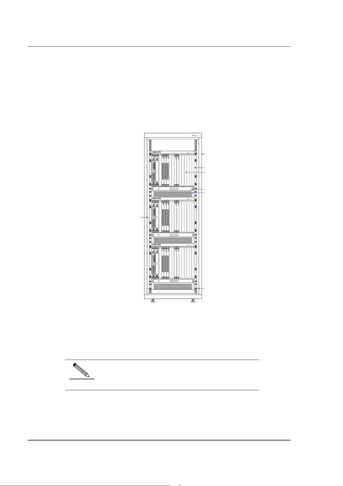
In the full configuration mode, 3 sets of 3P@C 4450E can be installed in a 19-inch standard cabinet
with the height of 2.2 m, as shown in Figure 2-10:
Figure 2-10 Full configuration of 3P@C 4450E
2.2 m cabinet
10U chassis
Service f unction
modules
1U fan module
2U air deflector
frame
ESD socket
Grounding
post
In the full configuration mode, the 3P@C 4450E system comprises 6 major parts: A standard 19-inch
cabinet with the height of 2.2 m, a 10U chassis, a 1U fan module, 2U air deflector frame, service
functional modules (including SMUB and ADSL/VDSL service boards) and the -48 V DC power
distribution system.
1. The -48 V DC power distribution system is on the rear of
the integrated equipment.
prompt
2. To connect to the 220 V AC power supply, it is necessary
to use the primary power supply system.
3P@C Installation Manual
Page 2-6 Reproduction and communication in any form prohibited without the written permission of SAGEM SA
Page 30

SAGEM 3P@C
2.3.
2.3. SMUB and Service Boards
2.3.2.3.
2.3.1.
2.3.1. Service Processor Unit Board (SMUB)
2.3.1.2.3.1.
1.1.1.1 Structure of the SMUB
As the control center of 3P@C 4450E, the SMUB is responsible for the data exchange and control
management of the system and it provides uplink interfaces for the ADSL and VDSL subscribers to
access the network.
The single-SMUB or dual-SMUB operating mode can be adopted for 3P@C 4450E. When the singleSMUB operating mode is adopted, SMUB can be inserted in slot 0 or 1 of the 10U chassis. Hot
backup can be implemented in the system when the dual-SMUB operating mode is adopted, in which,
two SMUBs can be inserted in slot 0 and slot 1 of the 10U chassis respectively. The SMUB in slot 0
serves as the active one, and the SMUB in slot 1 serves as the standby one, as shown in the following
figure:
Figure 2-11 Slots of the SMUB
Active
SMUB
Only the active SMUB is active at one time. The equipment can be managed only via the Console
interface on the active SMUB, and the Console interface on the standby SMUB is suspended.
The rear view of the SMUB is shown in Figure 2-12:
Standby
SMUB
3P@C Installation Manual
Page 2-7 Reproduction and communication in any form prohibited without the written permission of SAGEM SA
Page 31

Figure 2-12 Front view of the SMUB
System running
state LED
10/100 Base-TX
Uplink interface
SAGEM 3P@C
Upper puller
adapter
Console
interface
Uplink interface
extended slot
Lower puller
adapter
1.1.1.2
1.1.1.2 Interface features of the SMUB
1.1.1.21.1.1.2
Table 2-2 Interface features of the SMUB
Interface
name
Console
interface
Ethernet
uplink
interface
1.1.1.3
1.1.1.3 Extended slots of the SMUB
1.1.1.31.1.1.3
Quant
ity
Interface
type
Interface
attributes
Description
1 RJ-45 RS-232C Located at the uppermost of the
SMUB, the Console interface can
be used to manage and configure
3P@C 4450E via the command
line interface.
1 RJ-45 10/100Base
-TX
Located at the lowermost of the
SMUB, it is used to connect the
VDSL and ADSL subscribers to the
IP network.
The SMUB provides 2 extended slots for installing uplink interface modules. 3P@C 4450E supports
the following uplink interface modules:
Table 2-3 Type of uplink interface modules
Module type Name Description Interface
type
DS-1GLX 1-port gigabit long-
wave optical
interface module
DS-1GSX 1-port gigabit short-
wave optical
interface module
Providing 1 long-wave optical
uplink interface of 1G rate
Providing 1 short-wave optical
uplink interface of 1G rate
SC
SC
3P@C Installation Manual
Page 2-8 Reproduction and communication in any form prohibited without the written permission of SAGEM SA
Page 32

SAGEM 3P@C
Module type Name Description Interface
type
DS-2FSM 2-port 100M single-
mode optical
interface module
DS-2FMM 2-port 100M multi-
mode optical
interface module
DS-A155SM 1-port long-wave
single-mode ATM
optical interface
module
DS-A155MM 1-port short-wave
multi-mode ATM
optical interface
module
DS-4TXB 4-port 100M
electrical interface
module
DS-4ITX Value-added
service card
For the detailed description of uplink interface modules,
please refer to Section 2.5.
prompt
Providing 2 100Base-FX
uplink single-mode optical
interfaces
Providing 2 100Base-FX
uplink multi-mode optical
interfaces
Providing 1 155M long-wave
single-mode uplink ATM
optical interface
Providing 1 155M short-wave
multi-mode uplink ATM optical
interface
Providing 4 10/100Base-TX
uplink electrical interfaces
Providing 4 10/100Base-TX
uplink electrical interfaces
SC
SC
SC
SC
RJ-45
RJ-45
1.1.1.4
1.1.1.4 Indicators of the SMUB
1.1.1.41.1.1.4
The front panel of SMUB provides LEDs for indicating the system operating status and the Ethernet
interface working status. The administrator can judge the system operation status according to the
display of these LEDs so as to diagnose the network fault in time, reduce the operation loss and
improve work efficiency. Descriptions of the LED indicators are given in Table 2-4:
Table 2-4 Status definitions of the LED indicators on the SMUB
LED Identific
ation
System
running
status
indicator
Ethernet
interface
working
status
indicators
ALM Red
LINK Green
ACT Green
Color Status Description
Off The system does not operateRUN Green
FlashingThe system operates normally.
Off The system operates normally
ON System alarm. This LED flashes
once when the equipment is started
and conducts self-check. It does
not indicate any alarm at this time
Solid
on
Off The port is not connected
FlashingData are being received/transmitted
Off No data are being
The corresponding LED is solid on
after a stable connection is set up
at the port
on the port
received/transmitted on the port
3P@C Installation Manual
Page 2-9 Reproduction and communication in any form prohibited without the written permission of SAGEM SA
Page 33

SAGEM 3P@C
2.3.2.
2.3.2. VDSL Unit Board (VDUB)
2.3.2.2.3.2.
1.1.1.5
1.1.1.5 Structure of the VDUB
1.1.1.51.1.1.5
VDUB is the VDSL office end access service board of 3P@C 4450E. Each VDUB provides 24 VDSL
subscriber interfaces. The subscriber interface is connected to the DIN connector on the backplane,
thus implementing data transmission via the existing data switching line (such as telephone line) and
separation of data transmission from voice transmission.
The VDUB features high security and supports IEEE 802.1Q VLAN to provide secure isolation for
each subscriber. In addition, it supports the port locking function to prevent illegal subscribers from
accessing the network.
VDUB adopts the -48 V power supply with an allowable voltage ranging from -36 V to -72 V. It
supports hot plugging, and can identify the rack slots, thus facilitating the management and
maintenance.
When used in 3P@C 4450E, the VDUBs can be inserted in slots 2 ~ 15 of the 10U chassis, as shown
in the following figure:
Figure 2-13 Slots of the VDUB
The front view of the VDUB is shown in the following figure:
Figure 2-14 Front view of the VDSL
VDUB running
state LED
Lower puller adapter
The front panel of VDUB provides two groups of LEDs, as follows:
Upper puller
adapter
Subscriber interface
working state LED
VDUB running status indicators RUN and ALM, which are in the upper part of the
3P@C Installation Manual
Page 2-10 Reproduction and communication in any form prohibited without the written permission of SAGEM SA
Page 34

VDUB.
VDSL subscriber interface working status indicators, which are in the middle of the
VDUB. The VDUB provides 24 VDSL subscriber interfaces. The working status of
each interface is shown by two indicators, LINK and ACT.
1.1.1.6
1.1.1.6 Indicators of the VDUB
1.1.1.61.1.1.6
Descriptions of the LED indicators on the front panel of VDUB are given in Table 2-5:
Table 2-5 Status definitions of the LED indicators on the front panel of VDUB
SAGEM 3P@C
LED Identific
ation
VDUB
running
status
indicator
VDSL
subscriber
interface
working
status
indicators
2.3.3.
2.3.3. ADSL Unit Board (ADUB)
2.3.3.2.3.3.
1.1.1.7
1.1.1.7 Structure of the ADUB
1.1.1.71.1.1.7
RUN Green
ALM Red
LINK Green
ACT Green
Color Status Description
On The system is powered on
Off The system is powered off or
abnormal
Flashing The VDUB operates normally
Off The VDUB operates normally
ON VDUB alarm
Solid on The corresponding LED is solid
on after a stable connection is
set up at the subscriber interface
Off The subscriber interface is not
connected with any subscriber
Flashing Data are being
received/transmitted on the
subscriber interface
Off No data are being
received/transmitted on the
subscriber interface
The ADUB is used to provide ADSL data access services. Each ADUB provides 32 ADSL subscriber
interfaces. The subscriber interface is connected to the DIN connector on the backplane, thus
implementing data transmission via the existing data switching line (such as telephone line) and
separation of data transmission from voice transmission.
The ADUB features high security and supports IEEE 802.1Q VLAN to provide secure isolation for
each subscriber. In addition, it supports the port locking function to prevent illegal subscribers from
accessing the network.
ADUB adopts the -48 V DC power supply with an allowable voltage ranging from -44 V DC to -60 V
DC. It supports hot plugging, and can identify the rack slots, thus facilitating the management and
maintenance.
When used in 3P@C 4450E, the ADUBs can be inserted in slots 2 ~ 15 of the 10U chassis, as shown
in Figure 2-15:
3P@C Installation Manual
Page 2-11 Reproduction and communication in any form prohibited without the written permission of SAGEM SA
Page 35
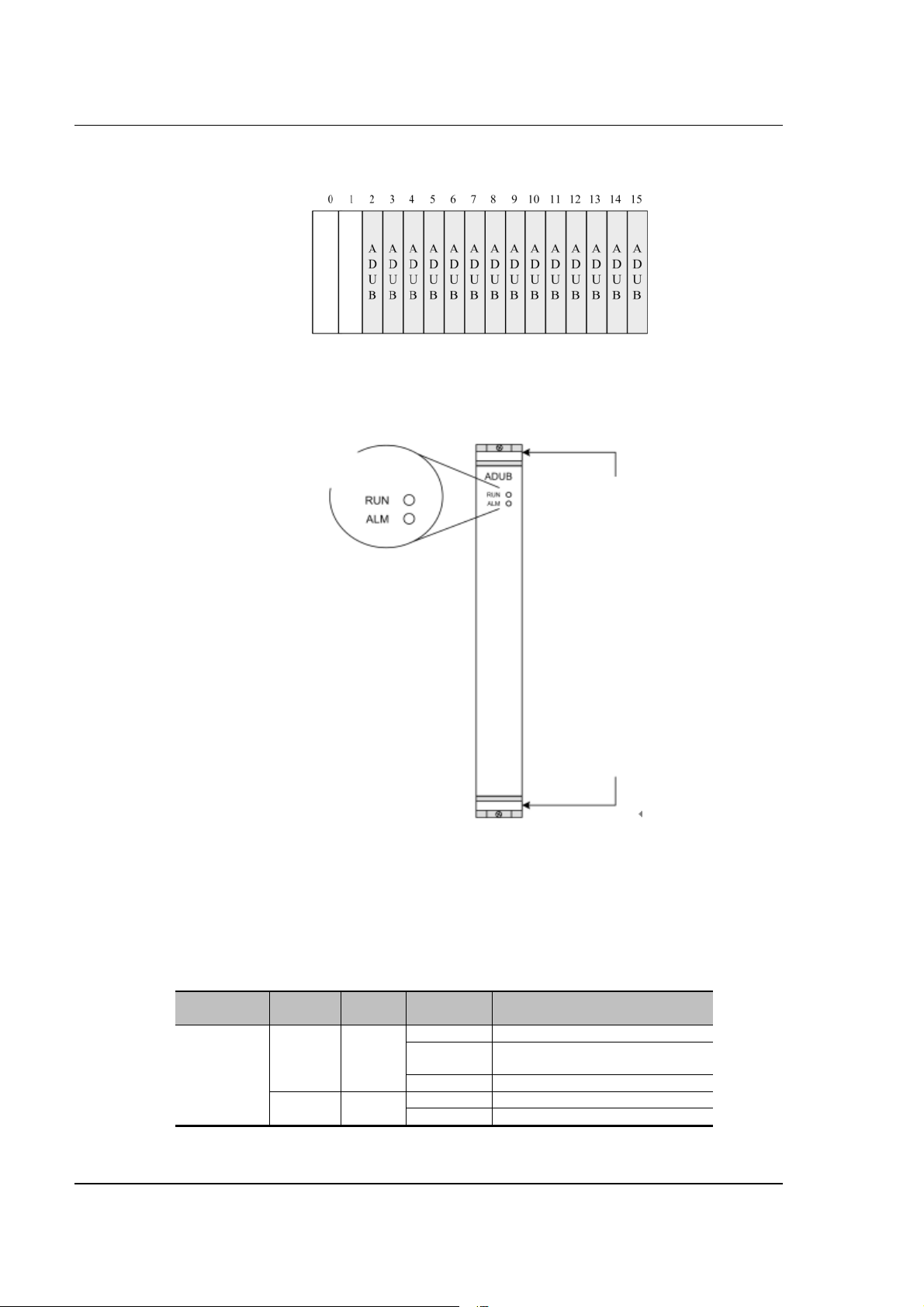
Figure 2-15 Slots of the ADUB
The front view of the ADUB is shown in the following figure:
Figure 2-16 Front view of the ADUB
ADUB running
state LED
SAGEM 3P@C
Upper puller
adapter
Lower puller
adapter
1.1.1.8
1.1.1.8 Indicators of the ADUB
1.1.1.81.1.1.8
The front panel of ADUB provides LED indicators showing the ADUB running status. Descriptions of
the LEDS are given in the following table.
Table 2-6 Status definitions of the LED indicators on the front panel of ADUB
LED Identific
ation
ADUB
running
status
indicator
RUN Green
ALM Red
Color Status Description
On The system is powered on
Off The system is powered off or
abnormal
Flashing The ADUB operates normally
Off The ADUB operates normally
ON ADUB alarm
3P@C Installation Manual
Page 2-12 Reproduction and communication in any form prohibited without the written permission of SAGEM SA
Page 36

SAGEM 3P@C
2.3.4.
2.3.4. ADSL Unit Card (ADUC)
2.3.4.2.3.4.
1.1.1.9
1.1.1.9 Structure of the ADUC
1.1.1.91.1.1.9
In addition to the same functions and features as the ADUB, the ADUC also has a line capture relay
that can be used together with the ADSL special-purpose test device to provide the wiring function.
When used in 3P@C 4450E, the ADUCs can be inserted in slots 2 ~ 15 of the 10U chassis, as shown
in the following figure:
Figure 2-17 Slots of the ADUC
The rear view of the ADUC is shown in Figure 2-18:
Figure 2-18 Front view of the ADUC
ADUC running
state LEDa
Upper puller
adapter
Lower puller
adapter
1.1.1.10
1.1.1.10 Indicators of the ADUC
1.1.1.101.1.1.10
The front panel of ADUC provides LED indicators showing the ADUC running status. Descriptions of
the LEDS are given in the following table.
3P@C Installation Manual
Page 2-13 Reproduction and communication in any form prohibited without the written permission of SAGEM SA
Page 37

SAGEM 3P@C
Table 2-7Status definitions of the LED indicators on the front panel of ADUC
LED Identific
ation
ADUC
running
status
indicator
2.4.
2.4. Power Distribution System
2.4.2.4.
2.4.1.
2.4.1. Overview
2.4.1.2.4.1.
The DC distribution unit of 3P@C 4450E adopts the -48 V DC power supply. It is 4U high and is fixed
to the upper part of the equipment rack rear. The -48 V DC input power is divided into 4 tributaries
whose outputs are controlled by air switches separately. Their connection relations are shown in
Figure 2-19:
Figure 2-19 Connection relations
RUN Green
ALM Red
Color Status Description
On The system is powered on
Off The system is powered off or
abnormal
Flashing The ADUC operates normally
Off The ADUC operates normally
ON ADUC alarm
2.4.2.
2.4.2. Functional Features
2.4.2.2.4.2.
Input requirements
1. -48 V single input.
2. -48 V input range: -36 ~ -72 V DC.
3. -48 V total input power: 3,300 W.
Output requirements
1. The -48 V power is output to 4 channels that are led out by wiring terminals and controlled by air
switches.
2. The rated current of the air switch is 32 A.
3P@C Installation Manual
Page 2-14 Reproduction and communication in any form prohibited without the written permission of SAGEM SA
Page 38
3. The output power of each -48 V output is 1,200 W.
Cable selection
SAGEM 3P@C
The -48V input cable and the BGND and PGND external connection cables are
The four -48V output cables and the BGND and PGND internal connection cables
2
16mm
blue, black and yellow-green power cables respectively.
are 6mm
2
blue, black and yellow-green power cables respectively.
For the connection of DC power supplies, refer to Section
4.3. To connect to the 220 V AC power supply, it is
prompt
2.5.
2.5. Optional Uplink Interface Modules
2.5.2.5.
necessary to use the primary power supply system.
The modular structure is adopted for 3P@C 4450E. Each 10U chassis has 16 slots, the former two of
which are for inserting the SMUB boards. The SMUB provides multiple optional types of uplink
interface modules to meet different user networking requirements. The following uplink interface
modules are supported:
Table 2-8 Types of uplink interface modules
Module type Model Description
Gigabit
interface
module
Megabit
interface
module
ATM interface
module
DS-1GLX 1-port gigabit long-wave optical
interface module
DS-1GSX 1-port gigabit short-wave optical
interface module
DS-2FMM 2-port 100M multi-mode optical
interface module
DS-2FSM 2-port 100M single-mode optical
interface module
DS-4TXB 4-port 100M electrical interface module
DS-4ITX 4-port 100M electrical interface module
DS-A155SM 1-port 155M long-wave single-mode
ATM optical interface module
DS-P155MM 1-port 155M short-wave multi-mode
ATM optical interface module
The following describes the commonly used gigabit interface module (DS-1GLX/DS-1GSX) and the
100M interface module (DS-2FMM/ DS-2FSM/ DS-4TXB/ DS-4ITX) respectively.
2.5.1.
2.5.1. 1-port Gigabit Long-wave Optical Interface Module (DS-1GLX)
2.5.1.2.5.1.
The DS-1GLX module provides 1 gigabit long-wave Ethernet optical interface. The physical interface
is a standard SC optical interface whose maximum transmission distance is 10 km. A pair of singlemode fibers is required for it. The fiber length and peer interface type depend on the real situation.
1.1.1.11
1.1.1.11 Structure of the DS-1GLX module
1.1.1.111.1.1.11
The front panel of the DS-1GLX module is shown in Figure 2-20:
3P@C Installation Manual
Page 2-15 Reproduction and communication in any form prohibited without the written permission of SAGEM SA
Page 39

SAGEM 3P@C
Figure 2-20 Front view of the DS-1GLX module
DS-1GLX gigabit
interface module
SC long-wave
optical interface
Status LED
The front panel of the DS-1GLX module is composed of the following parts:
1 standard SC gigabit long-wave optical interface
1 LINK status indicator
1 ACT status indicator
Of the above, the different states of LINK and ACT indicators show the port operating status. For
details, refer to Table 2-9.
1.1.1.12
1.1.1.12 Indicators of the DS-1GLX module
1.1.1.121.1.1.12
Table 2-9 Status definitions of the LINK and ACT LEDs on the DS-1GLX module
LED Color
LINK Green
1.1.1.13
1.1.1.13 Interface features of the DS-1GLX module
1.1.1.131.1.1.13
Display
state
Solid on After a stable connection between a port and the
Off The link on the port is down.
Flashing Data are being received/transmitted on the portACT Green
Off No data are being received/transmitted on the
Description
equipment is established, the indicator of the port
stays solid on.
port.
Table 2-10 Gigabit long-wave optical interface features of the DS-1GLX module
Module
type
DS-1GLX 1 SC 1000Base-LX9/125 µm
Quantity
of
interfaces
Interface
type
Interface
attributes
Fiber
specifications
single-mode
fiber with a
wavelength of
1,310 nm
Transmission
distance
10km
The fiber system is divided into two types by the optical transmission mode: Multi-mode fibers and
single-mode fibers. The single-mode fiber is the fiber that transmits signal in a single mode at the
given wavelength. Its core is about 4 ~ 10µm, which is quite small. The fiber features high
transmission bandwidth and large transmission capacity.
3P@C Installation Manual
Page 2-16 Reproduction and communication in any form prohibited without the written permission of SAGEM SA
Page 40

SAGEM 3P@C
To know more about fibers, please refer to the contents in
prompt
2.5.2.
2.5.2. 1-port Gigabit Short-wave Optical Interface Module (DS-1GSX)
2.5.2.2.5.2.
The DS-1GSX module provides 1 gigabit short-wave Ethernet optical interface. The physical interface
is a standard SC optical interface whose maximum transmission distance is 550 m. A pair of multimode fibers is required for it. The fiber length and peer interface type depend on the real situation.
1.1.1.14
1.1.1.14 Structure of the DS-1GSX module
1.1.1.141.1.1.14
The front panel of the DS-1GSX module is shown in the following figure:
Figure 2-21 Front view of the DS-1GSX module
Appendix C.
DS-1GSX gigabit
interface module
DS-1GSX gigabit
inter face module
Status LED
The front panel of the DS-1GSX module is composed of the following parts:
1 standard SC gigabit short-wave optical interface
1 LINK status indicator
1 ACT status indicator
Of the above, the different states of LINK and ACT indicators show the port operating status. For
details, refer to Table 2-11.
1.1.1.15
1.1.1.15 Indicators of the DS-1GSX module
1.1.1.151.1.1.15
Table 2-11 Status definitions of the LINK and ACT LEDs on the DS-1GSX module
LED Color
LINK Green
Display
state
Solid on After a stable connection between a port and the
Off The link on the port is down.
Flashing Data are being received/transmitted on the portACT Green
Off No data are being received/transmitted on the
Description
equipment is established, the indicator of the port
stays solid on.
port.
3P@C Installation Manual
Page 2-17 Reproduction and communication in any form prohibited without the written permission of SAGEM SA
Page 41

1.1.1.16
1.1.1.16 Interface features of the DS-1GSX module
1.1.1.161.1.1.16
Table 2-12 Interface features of the DS-1GSX module
SAGEM 3P@C
Module
type
DS-1GSX 1 SC 1000Base-
Quantity
of
interfaces
Interface
type
Interface
attributes
SX
Fiber
specifications
62.5/125 µm multimode fiber with a
wavelength of 850
nm
50/125 µm multimode fiber with a
wavelength of 850
nm
Transmi
ssion
distance
275m
550m
The fiber system is divided into two types by the optical transmission mode: Multi-mode fibers and
single-mode fibers. A multi-mode optical fiber is a fiber that transmits signals in multiple modes at a
given wavelength. Phase difference may occur in the multi-mode transmission because the lights of
different modes will transfer at different speeds along a line. As a result, transmission distortion will
occur and thus the transmission band will be restricted. Two specifications are available now for the
cores of multi-mode optical fibers: 62.5 µm and 50 µm. In ISO/IEC 11801, both the two modes are
recognized transmission media.
2.5.3.
2.5.3. 2-port 100M Multi-mode Optical Interface Module (DS-2FMM)
2.5.3.2.5.3.
The DS-2FMM module provides 2 100M multi-mode fast Ethernet optical interfaces. The physical
interface is a standard SC optical interface and the multi-mode fiber is used whose maximum
transmission distance is 2 km. Two pairs of multi-mode fibers are required for it. The fiber length and
peer interface type depend on the real situation.
1.1.1.17
1.1.1.17 Structure of the DS-2FMM module
1.1.1.171.1.1.17
The front panel of the DS-2FMM module is shown in the Figure 2-22:
Figure 2-22 Front view of the DS-2FMM module
DS-2FMM 100M
interface module
SC multi-mode
optical interface
Status LED
The front panel of the DS-2FMM module is composed of the following parts:
2 standard SC 100M multi-mode optical interfaces
2 LINK status indicator
2 ACT status indicator
3P@C Installation Manual
Page 2-18 Reproduction and communication in any form prohibited without the written permission of SAGEM SA
Page 42

SAGEM 3P@C
Of the above, the different states of LINK and ACT indicators show the port operating status. For
details, refer to Table 2-13.
1.1.1.18
1.1.1.18 Indicators of the DS-2FMM module
1.1.1.181.1.1.18
Table 2-13 Status definitions of the LINK and ACT LEDs on the DS-2FMM module
LED Color
LINK Green
ACT Yellow
1.1.1.19
1.1.1.19 Interface features of the DS-2FMM module
1.1.1.191.1.1.19
Display
state
Solid on After a stable connection between a port and the
Off The link on the port is down.
Flashing Data are being received/transmitted on the
Off No data are being received/transmitted on the
Description
equipment is established, the indicator of the port
stays solid on.
optical port.
optical port.
Table 2-14 Interface features of the DS-2FMM module
Module
type
DS-2FMM 2 SC 100Base-
2.5.4.
2.5.4. 2-port 100M Single-mode Optical Interface Module (DS-2FSM)
2.5.4.2.5.4.
Quantity of
interfaces
Interface
type
Interface
attributes
FMM
Fiber
specification
s
62.5/125
multi-mode
fiber
µm
Transmission
distance
2km
The DS-2FSM module provides 2 100M single-mode fast Ethernet optical interfaces. The physical
interface is a standard SC optical interface and the single-mode fiber is used whose maximum
transmission distance is 15 km. Two pairs of single-mode fibers are required for it. The fiber length
and peer interface type depend on the real situation.
1.1.1.20
1.1.1.20 Structure of the DS-2FSM module
1.1.1.201.1.1.20
The front panel of the DS-2FSM module is shown in the following figure:
3P@C Installation Manual
Page 2-19 Reproduction and communication in any form prohibited without the written permission of SAGEM SA
Page 43

SAGEM 3P@C
Figure 2-23 Front view of the DS-2FSM module
DS-2FSM 100M
interface module
SC single-mode
optical interface
Status
LED
The front panel of the DS-2FSM module is composed of the following parts:
2 standard SC 100M single-mode optical interfaces
2 LINK status indicator
2 ACT status indicator
Of the above, the different states of LINK and ACT indicators show the port operating status. For
details, refer to Table 2-15.
1.1.1.21
1.1.1.21 Indicators of the DS-2FSM module
1.1.1.211.1.1.21
Table 2-15 Status definitions of the LINK and ACT LEDs on the DS-2FSM module
LED Color
LINK Green
ACT Yellow
1.1.1.22
1.1.1.22 Interface features of the DS-2FSM module
1.1.1.221.1.1.22
Display
state
Description
Solid on After a stable connection between a port and the
equipment is established, the indicator of the port
stays solid on.
Off The link on the port is down.
Flashing Data are being received/transmitted on the
optical port.
Off No data are being received/transmitted on the
optical port.
Table 2-16 Interface features of the DS-2FSM module
Module
type
DS2FSM
Quantity
of
interfaces
Interface
type
Interface
attributes
2 SC 100Base-
FSM
Fiber
specifications
9µm singlemode fiber
Transmission
distance
15km
3P@C Installation Manual
Page 2-20 Reproduction and communication in any form prohibited without the written permission of SAGEM SA
Page 44

SAGEM 3P@C
2.5.5.
2.5.5. 4-port 100M Electrical Interface Module (DS-4TXB)
2.5.5.2.5.5.
The DS-4TXB module provides 4 100M fast Ethernet electrical interfaces. The physical interface is an
RJ-45 connector and the C5 twisted pair cable is used whose transmission distance is 100 m. The
MDI/MDIX self calibration function is supported. The cable length and peer interface type depend on
the real situation.
1.1.1.23
1.1.1.23 Structure of the DS-4TXB module
1.1.1.231.1.1.23
The front panel of the DS-4TXB module is shown in the following figure:
Figure 2-24 Front view of the DS-4TXB module
The front panel of the DS-4TXB module is composed of the following parts:
4 RJ-45 10/100M Ethernet electrical interfaces
4 ACT indicators
4 LINK indicators
Of the above, the different states of LINK and ACT indicators show the port operating status. For
details, refer to Table 2-17.
1.1.1.24
1.1.1.24 Indicators of the DS-4TXB module
1.1.1.241.1.1.24
Table 2-17 Status definitions of the LINK and ACT LEDs on the DS-4TXB module
LED Color
LINK Green
1.1.1.25
1.1.1.25 Interface features of the DS-4TXB module
1.1.1.251.1.1.25
Display
state
Solid on After a stable connection between a port and the
Off The link on the port is down.
Flashing Data are being received/transmitted on the portACT Yellow
Off No data are being received/transmitted on the
Description
equipment is established, the indicator of the port
stays solid on.
port.
Table 2-18 Interface features of the DS-4TXB module
Module
type
DS-4TXB 4 RJ-45 10/100Base-TXCategory-3/4/5
Quantity
of
interfaces
Interface
type
Interface
attributes
Fiber
specifications
shielded/unshie
lded twisted
pairs
Transmission
distance
100m
3P@C Installation Manual
Page 2-21 Reproduction and communication in any form prohibited without the written permission of SAGEM SA
Page 45

SAGEM 3P@C
2.5.6. VAS Card (DS-4ITX)
The VAS card (DS-4ITX) is developed to meet the growing demands of users for IN services.
Currently, it provides L2TP VPDN service, PPPoE Server Proxy service, network interface PPPoE
termination service, and VMAC service. It will provide the MPLS VPN service in the future.
Through software configuration, the VAS card can be loaded with different IN service FPGA logics to
support diversified IN services and flexibly meet the new market requirements.
The DS-4ITX module provides 4 100M fast Ethernet electrical interfaces. The physical interface is an
RJ-45 connector and the C5 twisted pair cable is used whose transmission distance is 100 m. The
cable length and peer interface type depend on the real situation.
1.1.1.26
1.1.1.26 Structure of the DS-4ITX module
1.1.1.261.1.1.26
The front panel of the DS-4ITX module is shown in the following figure:
Figure 2-25 Front view of the DS-4ITX module
The front panel of the DS-4ITX module is composed of the following parts:
4 RJ-45 10/100M Ethernet electrical interfaces
4 ACT indicators
4 LINK indicators
Of the above, the different states of LINK and ACT indicators show the port operating status. For
details, refer to Table 2-19.
1.1.1.27
1.1.1.27 Indicators of the DS-4ITX module
1.1.1.271.1.1.27
Table 2-19 Status definitions of the LINK and ACT LEDs on the DS-4ITX module
LED Color
LINK Green
Display
state
Solid on After a stable connection between a port and the
Off The link on the port is down.
Flashing Data are being received/transmitted on the portACT Yellow
Off No data are being received/transmitted on the
Description
equipment is established, the indicator of the port
stays solid on.
port.
3P@C Installation Manual
Page 2-22 Reproduction and communication in any form prohibited without the written permission of SAGEM SA
Page 46

1.1.1.28
1.1.1.28 Interface features of the DS-4ITX module
1.1.1.281.1.1.28
Table 2-20 Interface features of the DS-4ITX module
SAGEM 3P@C
Module
type
DS-4ITX 4 RJ-45 10/100Base
2.6.
2.6. Route Transfer Unit (RTU)
2.6.2.6.
Quantity of
interfaces
Interface
type
Interface
attributes
-TX
Fiber
specifications
Category-3/4/5
shielded/unshiel
ded twisted
pairs
Transmission
distance
100m
At present, some special application modes of 3P@C 4450E need to be supported by the RTU,
including the non-PPPoE packet filtering and user name binding in the L2 PPPoE transparent
transmission mode.
With the board structure, the RTU is composed of such components as chips, crystal
oscillators and resistance-capacitance devices. It does not provide any external interface. It
is installed on the SMUB (see Section 4.4.2 for its installation) and connected to the socket
on the SMUB via the pins on the board to provide the L3 routing and flow table functions. Its
structure is shown in the following figure.
Table 2-21 Structure of the RTU
Screw
hole
Connec tion
Front face
socket
Rear face
The RTU is optional. You may use it as required.
When 3P@C 4450E uses the 100M electrical interface uplink interface module,
though the RTU routing function can be provided, the L2 application mentioned
above will be limited. To perfectly support the L2 application, it is necessary to add
the RTU.
When 3P@C 4450E uses the gigabit electrical interface uplink interface module, the
L2 application mentioned above can be implemented without using the RTU.
When 3P@C 4450E uses the ATM interface uplink interface module, the RTU must be adopted so as
to provide the L2 application function mentioned above and the L3 function.
3P@C Installation Manual
Page 2-23 Reproduction and communication in any form prohibited without the written permission of SAGEM SA
Page 47

SAGEM 3P@C
3P@C Installation Manual
Page 2-24 Reproduction and communication in any form prohibited without the written permission of SAGEM SA
Page 48

CHAPTER 4
3. Installation Preparation
3.1.
3.1. Environmental Requirements
3.1.3.1.
3.1.1.
3.1.1. Temperature and Humidity Requirements
3.1.1.3.1.1.
To ensure the normal running of the equipment and prolong its service life, please make sure that
the temperature and humidity of the equipment room are within the allowed range of the equipment
operation.
The temperate shall range within -5°C ~ +50°C and the indoor temperature range of 18°C ~ 25°C is
recommended. Too high temperature will do great harm to the equipment and long-term high
temperature will accelerate the ageing of insulation materials, reduce the running stability of
components and even affect the service life of the equipment.
The humidity range shall range from 5% to 95%, preferably 20% ~ 60%. Too high humidity inside
the equipment room may cause poor insulation performance of the insulation materials or even
current leakage, which will cause short circuit or fire disaster. In addition, too high humidity will also
cause changes of the mechanical performance of the materials, oxidization of the metal part and
corrosion. However, too low humidity will cause the generation of static electricity.
3.1.2.
3.1.2. Cleanness Requirements
3.1.2.3.1.2.
Certain cleanness is required for the operating environment of the equipment and dust should be
avoided as much as possible, because dust will cause harm to the safe running of the equipment.
When dust falls down on the equipment body, it can cause static absorption and result in poor
contact of the metal plug-ins or metal contact points, especially when the indoor RH is slightly
lower. This will not only affect the service life of the equipment but also cause communication
failure. Furthermore, the dust falling down on the optical interface of an interface module installed
in the equipment will severely affect the interface data transmission or even cause transmission
interruption. Therefore, dustproof measures must be taken for the equipment room where the
equipment operates. It is recommended that the concentration of particles be less than 180 mg/ m
and such devices as printers and copying machines be place as far as possible from the
equipment, so as to prevent paper scraps and ink powder from being absorbed into the equipment
inside.
3.1.3.
3.1.3. Floor Requirements
3.1.3.3.1.3.
The equipment room floor shall first of all satisfy the bearing capacity requirement and it should be
dust proof, fire proof, insulated and wearproof. The floor can be made of linoleum flooring, ethylene
perchloride, resinous vanish or can be the anti-static raised floor. The antistatic floorboards should
be tightly fit and robust, with the horizontal error no greater than 2mm per square meter. The
ground or floor must be statically grounded and the resistance of the unit raised floorboards should
accord with the
connected to the grounding device via a current-limiting resistor and connection line.
Technical Specification for the Raised Floor in Computer Rooms. The floor can be
3
3P@C Installation Manual
Page 3-1 Reproduction and communication in any form prohibited without the written permission of SAGEM SA
Page 49

SAGEM 3P@C
The load bearing capacity of the equipment room floor should be more than 450 kg/m2 (when
storage batteries are contained in the cabinet). Considering the weight of the lead-acid battery, the
load bearing capacity of the floor of the battery room should be more than 500 kg/m
equipped with the battery below 500AH and more than 600 kg/m
above 800AH. The load bearing capacity of both the corridor and staircase should be 400 kg/m
(where there is no storage battery), with the overload coefficient being 1.4.The load bearing
capacity of other places except for the equipment room should not be lower than 300 kg/m
case of old buildings, the load bearing capability should be improved if the indices do not satisfy the
requirements.
2
when equipped with the battery
2
when
2
. In
3.1.4. Heat Dissipation Requirements
Good ventilation should be ensured for the operating environment of the equipment so as to meet
the heat dissipation requirements of the internal components of the equipment. In particular,
sufficient space (no less than 0.8 m) is required for both the front face and the rear face of the
equipment at the place near the fans. Air inlet and outlet should not be blocked and weights are not
permitted on the equipment.
3.1.5.
3.1.5. Power Supply Re quirements
3.1.5.3.1.5.
2
When –48V DC power is adopted to supply power to 3P@C 4450E, the allowed variation of the
voltage should be -36V ~ -72V when measured at the DC input terminal of each cabinet. When the
conductor of the DC discharge loop is selected, the through voltage dip of the DC discharge loop
should be no more than 0.5V and the core diameter of the DC power cable should be no less than
2
16mm
When AC power supply is adopted, reliable and stable AC mains power and lead-in wires should
be selected. Since 3P@C 4450E consumes little power, it can adopt the 220V single-phase threewire power supply system after conversion by the power transformation equipment. The
specifications of the power cable should be calculated according to the equipment quantity and
their power consumption, so as to meet the relevant specification requirements and taken into
account sufficient security. In its full configuration, the 3P@C 4450E switch needs more than
1200W power.
3.1.6.
3.1.6. Grounding Requirements
3.1.6.3.1.6.
When 3P@C 4450E is used in a large data communication office and is installed in a 19-inch
cabinet with DC power supply, according to the General Technical Requirements (Provisional) for
the Power Supply System of a Communication Office (Station) issued by the former Ministry of
Posts and Telecommunications, the working ground, the protection ground of all communication
equipment as well as the lightning protection ground of the building where the communication office
of 3P@C 4450E is located should share a centralized grounding mode via a group of grounding
devices, i.e. joint grounding mode.
When AC power supply is adopted for 3P@C 4450E, the power sockets (as shown in Figure 3-1)
using neutral point connectors are recommended and the neutral point of the power cable should
be reliably grounded in the building. Generally during the engineering cabling of the building, the
neutral points of the power supply system of the building have been buried and users should
confirm if the power supply of this building has been reliably grounded.
.
3P@C Installation Manual
Page 3-2 Reproduction and communication in any form prohibited without the written permission of
SAGEM SA
Page 50

Figure 3-1 Recommended power sockets
Neutral point
SAGEM 3P@C
Zero wire
Live wire
In order to ensure the definitely safe operation of the equipment, grounding in accordance with the
grounding treatment requirements is needed. At the upper back of the 3P@C 4450E cabinet, one
end of the grounding cable can be fixed and mounted at the grounding terminal while the other end
can connect the protection ground of the equipment room, or it can be buried under the ground or
connected to the grounding body inside the equipment room. The grounding resistance of the
grounding body should be less than 1 ohm and copper conductors with good conductivity should
be selected as the grounding cables with the section area no less than 16mm
2
.
The following grounding requirements are posed for 3P@C 4450E:
The grounding cables should be led into the equipment room by the horizontal
grounding busbar of the vertical grounding bus in the joint grounding device. The
grounding cable of each rack of the 3P@C 4450E equipment should be led into
the nearest horizontal grounding bus.
The DC power supply working ground of each rack in the 3P@C 4450E
equipment should be connected from the grounding bus.
Each rack equipment should have the working ground. The shell and cabinet
should have the protection ground.
The distribution frame should be connected with the protection ground via the
grounding bus. Meanwhile, the distribution frame should not be electrically
connected with the cabinet.
All communication equipment in the equipment, except for the grounding cable
close to the grounding bus, are not allowed to form the electrical connection by
the installed fastening bolts touching the steel reinforcement in the building.
The section area of the grounding cables (including the wires connecting the
cabinets to be grounded/the grounding wires with the horizontal grounding
busbars) should be determined on the basis of the possible maximum current
load. The grounding cables should be made of good conductors (copper) and
naked conducting wires are not allowed.
The joint grounding resistance of the communication office where the 3P@C
4450E is located should be less than 2 ohm.
The metal parts (e.g., walls and reinforcing steel bars inside pillars) of the
building itself should be preferably used as the downleads of the lightning
protection ground, and such downleads shall be electrically connected with one
another to balance the electric potential inside the building. The working ground
of 3P@C 4450E should be far away from the power equipment or the grounding
devices of the lightning protection ground as much as possible.
The grounding terminals must undergo anti-corrosion and anti-rust processing.
Meanwhile, the screws should all be tightened to ensure good contact.
Do not lay down the grounding cables and signal cables in parallel or in a twisted
manner to reduce their mutual interference.
3P@C Installation Manual
Page 3-3 Reproduction and communication in any form prohibited without the written permission of
SAGEM SA
Page 51

SAGEM 3P@C
The basic requirement of grounding is that the grounding
resistance should be little. During the engineering design, lowresistance grounding materials should be applied with sufficient
length, width and thickness to ensure that 3P@C 4450E meets
the grounding requirements. Ground piles can be buried deeply
under the ground to form a flat surface there, so as to ensure low
resistance for various frequencies. As the type of soil impacts the
prompt
3.1.7.
3.1.7. Anti-interference Requirements
3.1.7.3.1.7.
Any interfering sources from the equipment or outside the applied system may affect the equipment
in the capacitance coupling, inductance coupling, electromagnetic wave radiation, common
resistance (including the grounding system) and the conduction mode of conducting wire (power
supply line, signaling line and output wire). For this reason, note that:
grounding resistance most, chemical agents (resistance-reducing
agents) can be applied around the ground pile to reduce
resistance for areas where the soil conditions are poor.
Furthermore, the temperature and humidity of soil also have
impact on the grounding resistance and this should also be
considered during the engineering design.
Take effective power anti-interference measures for the power supply system.
Do not combine the working ground of 3P@C 4450E with the grounding device
or the lightning grounding device of the power equipment but keep the distance
between them as far as possible.
Keep far away from any large-power radio transmitting station, radar transmitting
station and high frequency strong current equipment.
Take electromagnetic shielding measures when necessary.
3.1.8.
3.1.8. Other Requirements
3.1.8.3.1.8.
The indoor should be bright enough for operation, preferably 500 ~ 750
lumen/m
The equipment room should be attended by designated persons or have other
burglar-proof measures.
The water supply and draining systems of the equipment room should be
designed in accordance with the normal water consumption and fire fighting
regulations, and sufficient fire protection devices should be equipped.
2
.
3P@C Installation Manual
Page 3-4 Reproduction and communication in any form prohibited without the written permission of
SAGEM SA
Page 52

SAGEM 3P@C
3.2.
3.2. Safety Requirements
3.2.3.2.
3.2.1.
3.2.1. Basic Safety Requirements
3.2.1.3.2.1.
To ensure the normal operation of the equipment and the human safety, please strictly obey the
following security instructions during the operation:
Carefully operate the equipment in accordance with the instructions given in this
manual.
Turn off the power before the equipment installation.
Confirm whether the power supply is connected.
Connect the power supply to a grounded socket to meet the European safety
standards.
Try not to place the power supply socket far away from the power inlet of the
equipment, so that the power socket can be directly turned off without removing
the power cable connected to the equipment in the case of power supply failure.
Avoid any liquid contacting the equipment, lest short circuits or current leakage
be caused.
Never place the equipment near any heat source, lest the operation performance
of the equipment be deteriorated or even the equipment be damaged. In
addition, avoid direct sunshine on the equipment.
Clean the equipment with soft and clean dry cloths and do not use any
detergents.
Do not wear any loose dress or jewelry (such as rings, necklace and bracelet).
Preferably the sleeves should be rolled during the operation. Make sure that the
installation of the switch on the rack will not entangle your clothes.
3.2.2.
3.2.2. Antistatic Requirements
3.2.2.3.2.2.
Many antistatic measures have been taken for 3P@C 4450E. However, if the static electricity in the
environment exceeds a certain range, it will cause damage to the circuits or even the whole
equipment; therefore, static electricity should be taken into account during the design of the
equipment room environment. The static induction comes from two aspects: 1) outside electric
field, such as high voltage power transmission lines and lightning stroke; 2) internal system, such
as indoor environment, floor materials and equipment structure.
Therefore, in order to avoid the damages caused by static electricity, please make sure to:
Ground the equipment and the floor well;
Keep the equipment room inside dust-proof;
Maintain appropriate temperature and humidity conditions;
The human static electricity can also damage the printed circuits and the internal
components. Therefore, when you touch the circuit board or the extended
module, please hold the edges of them instead of directly touching the circuits or
components to avoid damage to them caused by human static electricity. Where
necessary, wear an antistatic wrist strap and antistatic work uniform during the
operation.
3P@C Installation Manual
Page 3-5 Reproduction and communication in any form prohibited without the written permission of
SAGEM SA
Page 53

SAGEM 3P@C
3.2.3.
3.2.3. Avoiding Laser Damage
3.2.3.3.2.3.
While the equipment installed with a fiber interface module is operating, please
do not expose your eyes directly to these optical interfaces, lest the laser ray
from the interfaces cause eye damage.
It is suggested that protection covers for optical interfaces be placed on those
optical interfaces if they are not in use.
Wear safety glasses to protect your eyes if condition permits.
3.2.4.
3.2.4. Lightning Protection Requirements
3.2.4.3.2.4.
The equipment room building, if higher than 15 m, should be designed in accordance with the
lightning protection requirements for Class II civil buildings and structures.
During the anti-lightning design, measures should be taken to guard against the incursion of direct
stroke and the lightning current. In the areas where lightning occurs frequently, there is also the
phenomenon of side flash. So, some preventive measures against the side flash should be
adopted according to the actual situation during the design. For example, connect the outer metal
windows of the building with the lightning protection down lead. Along the height of the building, set
horizontal metal lightning protection straps on the outer wall at a certain interval to prevent the
lightning.
The following lightning protection measures shall be taken for the main building body of the
equipment room.
Install anti-lightning nets or anti-lightning straps on the parts of the building that
are subject to lightening.
Equipment the protruding objects such as the chimney, antenna with an
overhead conductor or arrester.
Ensure the sectional area of the downlead of the anti-lightning device is no less
than 2 mm
The grounding resistance of the building’s lightning protection grounding device should be no more
than 10 ohm. Before external cable and metal pipes etc. enter the building, they should be
grounded. When outdoor aerial cables directly enter a room, lightning arrester should be installed
at the point of entry. At the top of chimneys or antennas etc., lightning rods or lightning protection
rings should be added. For buildings and structures, it is advisable to use the steel reinforcement of
the reinforced concrete building slabs, beams, pillars and foundation as the discharge line for
lightning-protection devices.
In the past, the lightning protection ground of the building was separated from the ground of
telecom and power supply systems, and large distances were required between various grounding
devices. However, due to such reasons as small building sites, most of these requirements of
distance were not satisfied. In fact, they can not be separated in many circumstances, so it is
advisable to employ joint grounding systems for the lightning protection of the buildings. The joint
grounding system connects the operating ground and protection ground for telecom use and the
lightning protection ground of the building as well as the ground of the industrial frequency AC
power supply system together. The grounding resistance of joint grounding should be quite high.
Since the grounding resistance required for telecom is far less than 10
requirements for various telecom equipments are different, the joint grounding resistance shall be
determined according to the minimum resistance value of the various grounding devices.
2
, and their spacing is no more than 30 m.
ohm, while the grounding
It is advisable to employ the metal components of the building itself (such as reinforcing steel bars
inside walls and pillars) as the lead wires for lightning protection grounding, and these lead wires
should be electrically connected, so that the electric potentials inside the building are equilibrated.
3P@C Installation Manual
Page 3-6 Reproduction and communication in any form prohibited without the written permission of
SAGEM SA
Page 54

SAGEM 3P@C
To ensure the operation safety of the electrical interfaces on the
equipment, lightning protection measures must be taken when
Note
3.2.5.
3.2.5. Anti-seismic Design Requirements
3.2.5.3.2.5.
The quakeproof intensity of telecom equipment building should be designed one degree higher
than local construction intensity. Those equipment buildings in short of quakeproof intensity
requirements have to be strengthened. The construction departments should be invited to join the
design and its execution.
3P@C 4450E uses the following measures during the installation to withstand Richter 7
earthquake.
The 10U chassis of 3P@C 4450E uses light and strong aluminium alloy
structure. There are locking devices to fix the circuit boards within the cabinets.
When combining sever cabinets together in the installation, you can lock the top
between the two cabinets by two cabinet-combining boards, so that the multiple
cabinets are lined up to form integrity.
Consolidate the reinforcement between the cabinet of 3P@C 4450E and the
equipment room. Fasten the cabinet with the floor via its supports and feet.
When necessary, fasten the cabinet with the ceiling to make the cabinet
integrated with the equipment room framework.
the connection of the equipment involves outdoor cabling.
3.2.6.
3.2.6. Fireproof Design Requirements
3.2.6.3.2.6.
The fireproof design of the equipment room should accord with the Code of Design on Building Fire
Protection and Prevention
building shall have its fire-proof class reaching Class II and Class I (for high-rise buildings). In the
equipment room of 3P@C 4450E, emergency fire extinguishers should be equipped and automatic
fire alarm systems are recommended inside the equipment room.
issued by the state. As a key fire protection unit, any communication
3.2.7. Precautions for Equipment Handling
Preferably two or more persons are needed to move the equipment, lest the big
weight of the equipment accidentally cause damage to the human body.
Before dismounting or moving the equipment, cut off its power first.
3.3.
3.3. Installation Tools and Materials
3.3.3.3.
Unpack and inspect the equipment before installing it and place its components at a safe place.
When moving parts, please wear gloves lest that any sweat should corrode the metal parts of the
equipment.
The following tools are needed to install 3P@C 4450E:
One cross screwdriver
One straight screwdriver
One spanner
One pair of hydraulic pliers
3P@C Installation Manual
Page 3-7 Reproduction and communication in any form prohibited without the written permission of
SAGEM SA
Page 55

SAGEM 3P@C
One pair of scissors
One level bar
One percussion drill
One dust cleaner
Anti-static wrist strap
If the equipment is to be installed on the antistatic floor, an additional electric saw should be
prepared before the formal installation.
The following cables are needed for connection:
Power cables
Serial port console cables
Grounding cables
Network cables or fibers
Others that are needed include:
A computer with HyperTerminal software installed
The modules to be installed
3.4.
3.4. Product Configuration List
3.4.3.4.
3.4.1.
3.4.1. Basic Configuration of the Product
3.4.1.3.4.1.
Table 1-1 Basic configuration list of 3P@C 4450E
Item Name Quantity Description
1 3P@C 4450E-
IPDSLAM-10U general
chassis kit
2 Accessories for
installation
3 DC power cable 1 PCS Cut as required
4 Grounding cable 1 PCS Cut as required
3.4.2.
3.4.2. Optional Components
3.4.2.3.4.2.
Table 1-2 List of the optional components for 3P@C 4450E
Item Optional Component maximum
1 Service Processor Unit Board
(SMUB)
2 VDSL Unit Board (VDUB) 14 A suite of
3 ADSL Unit Board/Card (ADUB,
ADUC)
4 Route Transfer Unit (RTU) 1 ----5 1-port gigabit long-wave single-mode
interface module (
6 1-port gigabit short-wave multi-mode
interface module (
7 4-port 100M electric interface module
(
DS-4TXB)
8
VAS card (
DS-4ITX)
DS-1GLX)
DS-1GSX)
PCS
1
1 suite Including engineering labels, cable
3P@C Installation Manual
Including a 10U chassis, a
backplane, a fan module, a fan
mounting support and an air
deflector frame
ties, screws and RS-232C console
cables
Accessories
configuration
2 -----
14 A suite of
2×2 -----
2×2 -----
2×2 -----
2×2 -----
Needed
subscriber cables
subscriber cables
Page 3-8 Reproduction and communication in any form prohibited without the written permission of
SAGEM SA
Page 56

SAGEM 3P@C
Item Optional Component maximum
9 2-port 100M multi-mode optical
interface module (
10 2-port 100M single-mode optical
interface module (
11 1-port 155M long-wave single-mode
ATM interface module (DS-A155SM)
12 1-port 155M short-wave multi-mode
ATM interface module (DS-A155MM)
DS-2FMM)
DS-2FSM)
The maximum configuration quantity given in the above
table is applicable to each general chassis of 3P@C 4450E.
prompt
3.5. Unpacking for Acceptance
Keep the equipment waterproof and shock-proof during its
transportation. After the equipment arrives at the destination
Note
for installation, do not handle it roughly but keep it away
from sunlight and rain.
Accessories
configuration
2×2 -----
2×2 -----
2×2 -----
2×2 -----
Needed
3.5.1.
3.5.1. Preparation
3.5.1.3.5.1.
1.1.1.29
1.1.1.29 Checking the packages
1.1.1.291.1.1.29
Before unpacking, check if the packing box is intact and if the equipment model is consistent with
that specified in the purchase contract.
If the packing box is damaged or the equipment model is
inconsistent, please keep the original condition and contact
Note
1.1.1.30
1.1.1.30 Unpacking tools
1.1.1.301.1.1.30
the local office of SAGEM sa.
The needed tools for unpacking include a claw hammer or screwdriver and an antistatic wrist strap.
1.1.1.31
1.1.1.31 Participants
1.1.1.311.1.1.31
Both the customer and the engineering staff (engineers or representatives of SAGEM sa) should
be present during the unpacking. Otherwise, any goods problem shall be borne by the unpacking
party.
3P@C Installation Manual
Page 3-9 Reproduction and communication in any form prohibited without the written permission of
SAGEM SA
Page 57

SAGEM 3P@C
1.1.1.32
1.1.1.32 Storage environment requirements
1.1.1.321.1.1.32
Temperature: 10°C ~ 30°C.
Humidity: 30% ~ 70%.
There should be basically vibration-free, low dust concentration and free of
strong electromagnetic interference with good antistatic measures taken and
wide site space.
Preferably you should unpack inside or near the equipment
room to avoid hard moving of the equipment or damaged to
prompt
3.5.2.
3.5.2. Unpacking
3.5.2.3.5.2.
1.1.1.33
1.1.1.33 Packing box of the general chassis
1.1.1.331.1.1.33
The assembly wooden box is used as the packing box of 3P@C 4450E. It is connected and fixed
with plastic clips. Figure 3-2 shows its outside view.
Figure 3-2 Appearance of the packing box
the equipment.
Inside the packing box, there are packing materials such as foam pad, antistatic plastic bag and
desiccants. The equipment is placed in the antistatic plastic bag. Its upper edge, bottom edge and
all the corners are protected with the foam pads, and the foam pads are connected and fixed with
paper boards, as shown in Figure 3-3:
3P@C Installation Manual
Page 3-10 Reproduction and communication in any form prohibited without the written
permission of
SAGEM SA
Page 58

SAGEM 3P@C
Figure 3-3 Packing structure of the equipment inside the packing box
Air deflector frame
Fan module
Paper board
Foam pad
10U chassis
Packing box
The above figure indicates the structure of the packing box
inside and shows the packing materials such as antistatic
prompt
plastic bag and desiccant.
To unpack the packing box, take the following steps:
Step 1 Remove the outside packing materials.
Place the packing box as indicated and use a claw hammer or
screwdriver to remove the plastic clips around the top cover. The
upper cover can be opened.
Step 2 Remove the equipment packing materials.
Remove the packing materials (e.g. foam pads) on the equipment
and carefully and smoothly draw out the equipment. Remove the
packing plastic bag of the equipment.
If the equipment is moved from a place with low temperature
and low humidity to another place with high temperature and
high humidity, you have to wait at least 30 minutes before
unpacking it so as to avoid damages to the equipment
Note
caused by the moisture condensed on the equipment
surface.
Since the equipment is rather heavy, please operate it
carefully and avoid colliding with human or articles. Raise
and hold rigid places such as the rack base and skeleton to
Note
avoid damaging the equipment or any other accidents.
3P@C Installation Manual
Page 3-11 Reproduction and communication in any form prohibited without the written
permission of
SAGEM SA
Page 59

SAGEM 3P@C
1.1.1.34
1.1.1.34 Packing box of accessories
1.1.1.341.1.1.34
The packing box of accessories uses a small carton. Inside it there are a User Manual, a user
registration/warranty card, an antistatic wrist strap, subscriber cables and suite of packing
materials.
1.1.1.35
1.1.1.35 Packing box of boards
1.1.1.351.1.1.35
The packing box of boards usually adopts a carton. Inside the packing box, there are packing
materials such as foam pad, antistatic plastic bag and desiccants. After opening the carton, wear
an antistatic wrist strap first before taking the board out of the antistatic bag.
1. If a board is moved from a place with low temperature
and low humidity to another place with high temperature and
high humidity, you have to wait at least 30 minutes before
unpacking it so as to avoid damages to the board caused by
Note
the moisture condensed on the board surface.
2. You must wear an antistatic wrist strap before taking out
the board to avoid damage.
1.1.1.36
1.1.1.36 Cabinet packing box
1.1.1.361.1.1.36
The assembly wooden box is used as the packing box of the cabinet. It is connected and fixed with
plastic clips. Figure 3-4 shows its outside view. Inside the packing box, there are packing materials
such as foam pad, plastic bag, desiccant, cabinet, marking template and cabinet installation
instructions. The cabinet is placed in the antistatic plastic bag. Its upper edge, bottom edge and all
the corners are protected with the foam pads, and the foam pads are connected and fixed with
paper boards. Inside the cabinet there are guide rails.
Figure 3-4 Appearance of the cabinet packing box
3P@C Installation Manual
Page 3-12 Reproduction and communication in any form prohibited without the written
permission of
SAGEM SA
Page 60

To unpack the packing box of the cabinet, take the following steps:
Step 1 Open the upper cover. Place the packing box as indicated and use a
claw hammer or screwdriver to remove the plastic clips around the
top cover. The cabinet is exposed.
prompt
Since the cabinet is rather heavy, three to four persons are
needed to cooperate with one another in the unpacking
process.
Step 2 Erect the packing box and pull out the two cabinet feet. Erect the
packing box to its normal position. Hold the packing box and
carefully drag outward the cabinet from the side where the cover is
removed, until the two cabinet feet are dragged out of the packing
box. Remove the foam pads under the cabinet feet and place the
cabinet feet on the floor.
Step 3 Slightly lean the packing box along with the cabinet towards the side
where the cover is removed, and use the supports of the two cabinet
feet on the floor to draw back the packing box from the reverse
direction, as shown in Figure 3-5.
SAGEM 3P@C
prompt
Since the equipment is rather heavy, please operate it
carefully. Raise and hold rigid places such as the rack base
and skeleton to avoid damaging the equipment or any other
accidents.
Figure 3-5 Draw out the packing box backward from the reverse direction
3P@C Installation Manual
Page 3-13 Reproduction and communication in any form prohibited without the written
permission of
SAGEM SA
Page 61

SAGEM 3P@C
Step 4 Remove the packing materials of the cabinet such as the
plastic bag.
Step 5 Take out the marking template and the guide rails inside the
cabinet.
3.5.3.
3.5.3. Goods Acceptance
3.5.3.3.5.3.
After unpacking, inspect and accept the goods against the contract and the packing list as follows:
Appearance check: Check if the outer appearance of the equipment has any
defect, looseness or damage, and if the identifying words are legible, and if the
chassis boards and decorating plates are all installed and meet the requirements
for use.
Integrity check: Check if all the components and accessories needed for
installation of the equipment are complete and matched.
The engineering staff (engineers or representatives) of SAGEM sa should take
the main responsibility for checking electrically sensitive devices and
components.
Lay out the inspected goods according to their different types. Keep the
unpacked packing box at least till the user signs on the packing list.
The following basic assemblies are contained inside the packing box of 3P@C 4450E:
One set of 3P@C 4450E equipment (including a 10U chassis and the
backplane)
One fan module and one fan mounting support
One air deflector frame
One suite of installation accessories (including engineering labels, cable ties and
screws)
Suite of subscriber cables
DC power cable
One RS-232C console cable
One User Manual
User registration/warranty card
The assemblies of the actual purchased equipment and the
specific quantities of the components/accessories shall
depend on the onsite packing list or the purchase contract of
prompt
the purchased equipment.
If there is any product damaged or even lost in the box, contact the distributor or the most available
salesmen of SAGEM sa. Also please keep away all the packing materials for future packing of the
switch.
3P@C Installation Manual
Page 3-14 Reproduction and communication in any form prohibited without the written
permission of
SAGEM SA
Page 62

CHAPTER 4
4. Equipment Installation and Connection
Do not take down the “no dismount” seal of SAGEM sa on
the chassis of 3P@C 4450E without prior consent of
SAGEM sa. This seal must be intact before the agent or
engineer of SAGEM sa maintain the 3P@C 4450E
equipment you have purchased. If you really need to
Note
Only qualified technicians are allowed to install and maintain 3P@C 4450E and these technicians
must receive sufficient technical training or have rich installation and operation experience.
Before installing 3P@C 4450E, check if the needed installation tools and materials are complete. Then remove
the packing box of the equipment, take out the equipment and place in on the flat floor. Next, you can install the
equipment in the following steps:
To install 3P@C 4450E, take the following steps:
Step 1 Install the 19’’ standard cabinet 2.2 m high.
Step 2 Install the equipment.
Step 3 Connect the power and grounding cables.
Step 4 Install the Service Processor Unit Board (SMUB).
Step 5 Install the service cards such as ADUB, ADUC
Step 6 Install dummy panels.
Step 7 Connect the subscriber cables.
Step 8 Connect the console cable.
dismount the chassis cover, please contact your agent to
get the permission first. Otherwise, any consequences such
as lack of maintainability caused by arbitrary operations
shall be born by the user itself.
and VDUB.
4.1.
4.1. Cabinet Installation
4.1.4.1.
By the specific equipment room environment, the 19-inch standard cabinet 2.2 m high can be installed on the
cement floor or antistatic floor inside the equipment room. Figure 4-1 shows the flow chart of cabinet installation.
Figure 4-1 Cabinet installation flow chart
19'' cabinet
installation
The an tis tat ic
floor is availab le
Ins tall ation on
the c ement floo r
End the
ins tallation
3P@C Installation Manual
Page 4-1 Reproduction and communication in any form prohibited without the written permission of SAGEM SA
Installation on the
antis tatic f loor
Page 63

The cabinet of 3P@C 4450E weighs about 150 kg and so
two professional installers are needed to install it. The side
of the rack shall not be less than 0.1 m away from the wall
surface, and the back of the rack shall keep a space of more
than 0.8 m from the wall surface and other equipments
Note
(including the operation console chairs/desks), so as to
facilitate heat dissipation and equipment maintenance. The
distance between the front face of one cabinet row and that
of its adjacent row should be no less than 0.8 m.
The equipment installation space is illustrated in Figure 4-2.
Figure 4-2 Equipment installation space
Inner wall or
other barriers
4-f60.0 (Feet
position mark)
Use M12 expansion bolt
4-f60.0 (Feet
position mark)
Use M12 expansion bolt
SAGEM 3P@C
4.1.1.
4.1.1. Installation on the Cement Floor
4.1.1.4.1.1.
The 19-inch cabinet 2.2 m high is installed on the cement floor by using pressure plates to press on the feet.
Since the feet have the insulating function and the pressure plate assembly contains insulating parts, the whole
equipment is insulated from the earth before the grounding cable is connected and the insulating requirements
can be effectively satisfied. See Figure 4-3 for the installation flow.
3P@C Installation Manual
Page 4-2 Reproduction and communication in any form prohibited without the written permission of SAGEM SA
Page 64

Figure 4-3 Flow of cabinet installation on the cement floor
Installation on
the c ement floor
Cabinet
positioning
Cabinet leveling
Cabinet fixation
Insulation test
Test passed?
SAGEM 3P@C
End the
installation
1.1.1.37
1.1.1.37 Position the cabinet
1.1.1.371.1.1.37
A. Marking
Decide the positions to install the expansion bolts according to the reference size and the positions of the feet in
the construction plane design drawings. Determine the mounting hole positions of the 2.2m cabinet and locate
the mounting hole positions of the feet with a marking template. (Note that the marking template is made of rigid
paper boards, placed in the packing wooden box of the 2.2 m standard cabinet and delivered along with the
cabinet). To avoid errors, repeat the measurement against the installation hole location diagram after all the hole
positions have been marked and make sure their sizes are correct. Figure 4-4 shows the mounting hole layout of
a single cabinet and Figure 4-5 shows that of two cabinets.
3P@C Installation Manual
Page 4-3 Reproduction and communication in any form prohibited without the written permission of SAGEM SA
Page 65

Figure 4-4 Mounting hole positions for a single cabinet
Inner wall or
other barriers
4-f60.0 (Feet
position mark)
Use M12 expansion bolt
SAGEM 3P@C
Figure 4-5 Mounting hole positions for two cabinets
Inner wall or
other barriers
4-f60.0 (Feet
position mark)
Use M12 expansion bolt Use M12 expansion bolt
4-f60.0 (Feet
position mark)
3P@C Installation Manual
Page 4-4 Reproduction and communication in any form prohibited without the written permission of SAGEM SA
Page 66

SAGEM 3P@C
B. Drilling
Drill a hole in the place marking expansion bolts with a percussion drill. The drill bit should be 14 or 16.To
drill a hole, keep the drill bit vertical with the surface and hold tightly the drill handle and do not shake, lest the
surface be damaged and the hole be slanted. The depth of the hole should be the length of the expansion bush
plus the cone. All holes must be consistent in the depth. Remove the dust out of the hole while measuring the
hole depth in order to get the net depth. While drilling, use a cleaner to remove the dust.
If the surface is too smooth and solid to locate the drill bit, you can cut a concave with a punching bit to help
position the drill bit.
When the 14 drill bit is selected but the hole diameter is small, enlarge the hole size through appropriate
technical treatment.
Marking and drilling are the basic work of the equipment
hardware installation. If they are inaccurate, it will cause
Note
C. Install the expansion bolts
Before the installation, use a cleaner to clean the inside and outside of all the holes and then measure the space
between holes. For holes with large deviation, it is necessary to reposition and re-drill the holes. Take out the
gasket and nut of the expansion bolt, place the expansion rod and expansion bush vertically into the hole and
hammer the expansion bolt with a rubber hammer until it goes fully into the ground.
great inconvenience to the later work. So their quality is the
prerequisite to the whole project quality.
1.1.1.38
1.1.1.38 Level the cabinet
1.1.1.381.1.1.38
A. Place the cabinet in position
Place the cabinet in the planned position (note: The cabinet feet must be aligned with their position marks and
the front/rear door positions of the cabinet should not be inversed. In the 2.2 m cabinet, the product label or
nameplate is attached on the front door). Screw the nut at the root of the feet with a spanner so that the cabinet
bottom face is 76 mm away from the floor and all cabinets are aligned with one another.
B. Level the cabinet
Place a horizontal ruler at the plane at the top of cabinet in two perpendicular directions, to check its horizontal
level. Fine tune the cabinet feet so that the cabinet becomes level and then tighten the locking nuts of the
cabinet feet.
1.1.1.39
1.1.1.39 Fix the cabinet
1.1.1.391.1.1.39
A. Cabinet bottom fixation
Put back the pressure plate assembly in the sequence as shown in Figure 4-6, so that the pressure plate
presses against the cabinet feet and use a torque wrench to fasten the bolt of the pressure plate assembly to
45Nm and thus fix the cabinet bottom. Figure 4-7 shows the effect after a single cabinet has been installed.
3P@C Installation Manual
Page 4-5 Reproduction and communication in any form prohibited without the written permission of SAGEM SA
Page 67

Figure 4-6 Installation sequence of the pressure plate assembly
SAGEM 3P@C
Feet
Pressure
plate
Nut
Spring
washer
Flat washer
Ins ul at io n
sleeve
Insulati on pad
Expansion bolt
Figure 4-7 Completion of the installation of a single cabinet
Cement floor
When multiple cabinets are to be combined, the following
installation steps shall be also taken.
Note
B. Cabinet top fixation
When two or more cabinets are combined, the inter-cabinet connection is needed (note that the cabinet side
panels do not need to be dismounted during the connection of the two combined cabinets). Figure 4-8 shows the
position of the inter-cabinet connecting board before the cabinets are combined. Release the inter-cabinet
connecting board of the cabinet on the right and install it in the way as shown in Figure 4-9. The effect upon
completion of installing the cabinet is shown in Figure 4-10.
3P@C Installation Manual
Page 4-6 Reproduction and communication in any form prohibited without the written permission of SAGEM SA
Page 68

SAGEM 3P@C
Figure 4-8 The connecting boards before combining two cabinets side by side
Figure 4-9 The connecting boards after combining two cabinets side by side
Figure 4-10 Effect after the installation of two combined cabinets
1.1.1.40
1.1.1.40 Insulation test
1.1.1.401.1.1.40
Set the multimeter to the resistor range to measure the resistance between the bolt of the pressure plate
assembly and the cabinet. If the circuit is disconnected, end the installation. Otherwise, it indicates the cabinet is
not insulated from the supports. In this case, remove all the pressure plate assemblies to check if any insulation
sleeves or pads of the supports are missing or any insulation parts are damaged. Then install the pressure plate
assemblies again and repeat the insulation test.
3P@C Installation Manual
Page 4-7 Reproduction and communication in any form prohibited without the written permission of SAGEM SA
Page 69

SAGEM 3P@C
4.1.2.
4.1.2. Installation on the Antistatic Floor
4.1.2.4.1.2.
When the 19-inch cabinet 2.2 m high is installed on the antistatic floor of the equipment room, it shall use the
A600 series supports. The cabinet is fixed by using pressure plates to press on the feet. Since the feet have the
insulating function and the pressure plate assembly contains insulating parts, the whole equipment is insulated
from the earth before the grounding cable is connected and the insulating requirements can be effectively
satisfied.
The purpose of the supports is to support the cabinet and facilitate the floorboard layout and cabling of the
equipment. Each support is welded from steel plates and its installation shall be in the mode of floor brackets,
that is, the floor is located between the cabinet and the supports and bolts thread through the antistatic floor to
fix the cabinet with the supports, thus achieving the purpose of cabinet fixation and support.
Figure 4-11 Appearance of the A600 series support
Connection hole
(used for 19'' cabinet)
Connection hole
(used for 19'' cabinet)
Upper
support
Lower
support
Mounting
hole
There are four components of the A600 series support: Three with adjustable height and one with fixed height.
The applicable height of the antistatic floor is from 260 mm to 410 mm.
The height of ESD protection floor refers to the distance
from the upper plane of the floor to the surface of the
cement floor. The A600 series support components can
implement steeples adjustment within their adjustable
prompt
ranges by means of the relative movement of the upper and
lower supports.
Each 19-inch cabinet uses two supports. Figure 4-12 shows the completed installation of a single cabinet on the
antistatic floor:
3P@C Installation Manual
Page 4-8 Reproduction and communication in any form prohibited without the written permission of SAGEM SA
Page 70
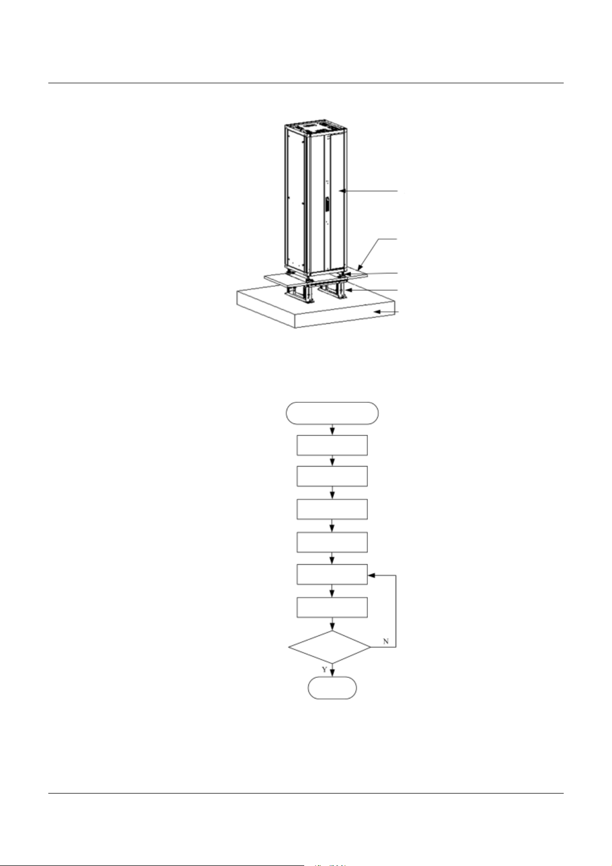
Figure 4-12 Completion of the installation of a single cabinet
See Figure 4-13 for the installation flow.
SAGEM 3P@C
Cabinet
Antistatic
floor
Pressure
plate
Support
Cement
floor
Figure 4-13 Flow of the cabinet installation on the antistatic floor
Installation on the
antistatic f loor
Cabinet
positioning
Support
positioning
Mounting support
Cabinet leveling
Cabinet fixation
Insulation test
Test passed?
End the
installation
3P@C Installation Manual
Page 4-9 Reproduction and communication in any form prohibited without the written permission of SAGEM SA
Page 71

SAGEM 3P@C
1.1.1.41
1.1.1.41 Position the cabinet
1.1.1.411.1.1.41
A. Determine the cabinet installation position
The position of the cabinet should be determined according to the benchmark sizes specified in the floor design
of the equipment room. In determining the installation positions, avoid interference between the mounting
support and the skeleton of the antistatic floor, i.e., try to keep the integrity of the floor skeleton. If such
interference is inevitable, remove the skeleton of the floor board where the interference occurs. It is
recommended that the center of the cabinet coincide with the center of the floorboard and all sides of the cabinet
shall be symmetrical to the central symmetric line of the antistatic floor board. If multiple cabinets are to be
installed side by side, the first cabinet should be arranged in this way.
B. Marking
Place the marking template of the cabinet (placed in the packing wooden box of the cabinet) on the antistatic
floor according to the cabinet arrangement. The cabinet marking template is illustrated in Figure 4-14. Mark all
the cabinet connection holes (four per cabinet) on the floor according to the marking template diagram, the feet
position marks (four feet per cabinet) and the cabling hole positions. The semicircle gap of the template indicates
the front direction of the rack. Mark the positioning and mounting holes of the supports on the cement floor.
Make sure that the direction of the template is correct.
Note
Figure 4-14 Cabinet marking template
4-f28 (Feet position mark)
f14 Use M12 expansion bolt
Back
C. Drill holes in the anti-static floor
Remove the marking template and drill a through-hole at each connection hole position on the antistatic floor
using a percussion drill with the
Φ20 drill bit. To drill a hole, keep the drill bit vertical with the antistatic floor and
hold tightly the drill handle and do not shake, lest the hole be slanted.
3P@C Installation Manual
Page 4-10 Reproduction and communication in any form prohibited without the written permission of SAGEM SA
Page 72

SAGEM 3P@C
Marking and drilling are the basic work of the equipment
hardware installation. If they are inaccurate, it will cause
Note
D. Cut out the holes
Cut out the through-holes with an electric saw on the antistatic floor according to the cabling hole marks.
1.1.1.42
1.1.1.42 Position the supports
1.1.1.421.1.1.42
A. Mark lines on the cement floor
Place the supports beneath the antistatic floor and align the connection holes on the supports to the holes on the
antistatic floor. With the support mounting holes as the template, make the position marks of the expansion bolts
on the floor.
Note
great inconvenience to the later work. So their quality is the
prerequisite to the whole project quality.
Strictly obey the method shown in Figure 4-15 to install the
supports and make sure the connection holes at the inner
side of the supports are aligned with the holes on the floor
while preventing the supports from shielding the cabling
holes as much as possible.
Figure 4-15 Connection positions of the mounting holes for the support and the antistatic
floor
Connection hole
(inner side)
W ire outlet of the floor
Antistatic f loor
B. Drill holes in the cement floor
The support is fixed to the floor by means of expansion bolt M12. Normally a percussion drill is used to drill holes
and the
14 or16 drill bit is selected. To drill a hole, keep the drill bit vertical with the surface and hold tightly
the drill handle and do not shake, lest the surface be damaged and the hole be slanted. The depth of the hole
should be the length of the expansion bush plus the cone. All holes must be consistent in the depth. Remove the
dust out of the hole while measuring the hole depth in order to get the net depth. While drilling, use a cleaner to
remove the dust.
3P@C Installation Manual
Page 4-11 Reproduction and communication in any form prohibited without the written permission of SAGEM SA
Page 73

SAGEM 3P@C
1.1.1.43
1.1.1.43 Install the supports
1.1.1.431.1.1.43
A. Install the expansion bolts
Before installation, use a vacuum cleaner to remove the dust inside and outside all the hole positions and then
measure the distance between the holes. Place the supports inside the holes to see whether the holes match
them. Do not mount the expansion bolt with large deviation to the holes. Instead, locate and drill the holes again.
Take out the gasket and nut of the expansion bolt, place the expansion rod and expansion bush vertically into
the hole and hammer the expansion bolt with a rubber hammer until it goes fully into the ground.
B. Adjust the supports
Roughly adjust the supports to their predefined height and fine tune the height-locking bolt of each support till the
upper support will not automatically slip. Place the supports at their installation positions and thread the
expansion bolts through the mounting holes on the supports.
C. Fix the supports
Align the holes on the antistatic floor with the connection holes on the support, screw in the bolts M12
×70 from
the top down, and place the pressure plate assemblies in the method shown in Figure 4-16. Slightly knock the
supports with a rubber hammer and fine tune their height. Make the antistatic floorboard fall on the skeleton of
the floor according to its original position and ensure that the upper surface of the supports is closely pressed
against the antistatic floorboard. Then use a torque wrench to fasten the bolt of the pressure plate assembly, the
expansion bolt and the height-locking bolt of the support all to 45Nm. In this process, fasten the bolts in the
middle first before fastening the bolts at the two sides. Figure 4-17 shows the fastening of the bolts.
Figure 4-16 Assembly chart of the pressure plate assembly
Spring
washer Φ 12
Washer
Support
insulation sleeve
Insu latio n
pad
Bolt M12x80
Pressure
plate
The above procedure shall be strictly obeyed to fasten the
above three groups of bolts.
Note
3P@C Installation Manual
Page 4-12 Reproduction and communication in any form prohibited without the written permission of SAGEM SA
Page 74

Figure 4-17 Positions of the bolts to be fastened
1.1.1.44
1.1.1.44 Fix the cabinet
1.1.1.441.1.1.44
A. Level the cabinet
Bolt of the pressure
Wire outlet
Height-locking
bolt (middle)
Sequence of fastening the bolts: B olt of the pressure
plate assembly ¡ú Expansion bolt ¡úHeight-locking bolt
(middle) ¡úHeight-locking bolt (si de)
plate assembly
Antistatic floor
Height-locking
bolt (side)
Expansion bolt
SAGEM 3P@C
Restore all the antistatic floorboards to their original state. Loosen all the bolts on the pressure plate assemblies
and remove the pressure plate assemblies. Push the cabinet to the predefined position (the cabinet feet must
coincide with their position marks) and screw the four feet with a spanner, so that the bottom surface of the
cabinet is 73 mm away from the floor and all cabinets are aligned. Place a horizontal ruler at the plane at the top
of cabinet in two perpendicular directions, to check its horizontal level. Fine tune the cabinet feet so that the
cabinet becomes level and then tighten the locking nuts of the cabinet feet.
B. Fix the cabinet
Put back the pressure plate assembly again, so that the pressure plate presses against the cabinet feet and use
a torque wrench to fasten the pressure plate assembly bolt to 45 Nm.
Please skip Step C below to install a single cabinet.
Note
C. Cabinet top fixation
When two (or more) cabinets are combined, it is necessary to connect the combined cabinets. Figure 4-8 shows
the position of the inter-cabinet connecting board before the cabinets are combined. Release the inter-cabinet
connecting board of the cabinet on the right and install it in the way as shown in Figure 4-9. Figure 4-18 shows
the effect after two cabinets are combined.
3P@C Installation Manual
Page 4-13 Reproduction and communication in any form prohibited without the written permission of SAGEM SA
Page 75

SAGEM 3P@C
Figure 4-18 Completion of the installation of two combined cabinets
1.1.1.45
1.1.1.45 Insulation test
1.1.1.451.1.1.45
Set the multimeter to the resistor range to measure the resistance between the bolt of the pressure plate
assembly and the cabinet. If the circuit is disconnected, end the installation. Otherwise, it indicates the cabinet is
not insulated from the supports. In this case, remove all the pressure plate assemblies to check if any insulation
sleeves or pads of the supports are missing or any insulation parts are damaged. Then install the pressure plate
assemblies again and repeat the insulation test.
4.1.3.
4.1.3. Installing the Cabinet Guide Rails
4.1.3.4.1.3.
Before installing the equipment, install the guide rails first inside the cabinet to bear the equipment. The
installation steps are as follows:
Step 1 Determine the installation positions of guide rails.
Determine the installation positions of the guide rails according to the quantity of the chassis to be installed, and
the cabling direction. Measure the installation positions and mark them.
Guide rails are needed to install the 10U chassis and the fan
module, but not needed for the air deflector frame (it only
prompt
Step 2 Install the guide rails.
After determining the installation positions, fasten the guide rails at such positions inside the cabinet with screws,
as shown in Figure 4-19.
needs hangers to get fixed).
3P@C Installation Manual
Page 4-14 Reproduction and communication in any form prohibited without the written permission of SAGEM SA
Page 76

Figure 4-19 Guide rail
Screw hole
The front view of the installed guide rails is illustrated in the following figure.
SAGEM 3P@C
Guide rail
Figure 4-20 Front view of the guide rails installed
4.2.
4.2. Installing the Equipment
4.2.4.2.
3P@C 4450E must be installed in a cabinet. Since it is heavy and of a large volume, two persons are needed to
cooperate with each other in the installation process. To install it, first install the 10U chassis, then the fan
module and finally the air deflector frame. The specific procedure is as follows:
4.2.1.
4.2.1. Installing the 10U Chassis
4.2.1.4.2.1.
If the 10U chassis has been mounted with hangers, you can
prompt
skip Step 1 and start the installation directly from Step 2.
Step 1 Mount the hangers with screws provided in the installation
accessories onto the 10U chassis, as shown in the following figure.
In the process, make sure the hangers are mounted in the correct
direction; otherwise the switch would not be able to be placed in
the standard cabinet.
3P@C Installation Manual
Page 4-15 Reproduction and communication in any form prohibited without the written permission of SAGEM SA
Page 77

Figure 4-21 Fixing the hangers onto the 10U chassis
Hanger
Side view of the
installation
Step 2 Hold the two edges of the 10U chassis and slowly slide it inward
from the front face of the rack, till the hangers bit the rack.
Step 3 Align the screw holes on the front face of the hangers with the
screws on the rack and fasten them with screws to ensure the
stability of the equipment, as shown in Figure 4-22.
Figure 4-22 Insert the 10U chassis into the rack and fix it
SAGEM 3P@C
4.2.2.
4.2.2. Installing the Fan Module
4.2.2.4.2.2.
The fan module should be installed below the 10U chassis in the following steps:
Step 1 Install the fan support and connect the hangers at the two
sides of the fan support with screws, as shown in the following
figure.
3P@C Installation Manual
Page 4-16 Reproduction and communication in any form prohibited without the written permission of SAGEM SA
Page 78

Figure 4-23 Install the fan supports
Step 2 Install the fan module. Insert the fan module into the fan
support and tighten the captive screws on the two sides after
the fan module is in position, as shown in Figure 4-24.
Figure 4-24 Install the fan module
SAGEM 3P@C
Captive screw
Generally, the fan module delivered has already been
mounted with hangers. If not, you can install the hangers
first according to Step 1 above for the installation of the 10U
prompt
chassis.
The fan module contains six DC fans that weigh about 3 kg. To make the replacement and cleaning of the fans
much easier, the fan module of 3P@C 4450E is designed to be dismountable. As shown in Figure 4-25, a puller
adapter is designed in the front face of the fan module. This puller adapter is closed when not in use. When it is
needed to dismount, replace or clean the fans, please operate this puller adapter with both hands.
Step 1 Wear the antistatic wrist strap and insert its plug into the ESD
socket in the front face of the 19-inch cabinet 2.2 m high.
Step 2 Cut off the system power supply of 3P@C 4450E before inspecting
the fan module for a long while (more than 5 minutes).
Step 3 Loosen the fastening screws at the two sides of the fan module
with a screwdriver.
Step 4 Press down the white left end of the puller adapter in the middle of
the fan module panel. The puller adapter will automatically eject
out, as shown in Figure 4-25.
3P@C Installation Manual
Page 4-17 Reproduction and communication in any form prohibited without the written permission of SAGEM SA
Page 79

Figure 4-25 Operate the puller adapter
Alarm LED
Screw
SAGEM 3P@C
Press
inward
3P@C Installation Manual
Page 4-18 Reproduction and communication in any form prohibited without the written permission of SAGEM SA
Page 80

SAGEM 3P@C
Step 5 Drag the puller adapter to pull out the fan module by 10 cm from
the chassis so that the fan module is detached from the internal
power socket of the chassis.
Step 6 Wait for a minute till the fans fully stop running if you dismount the
fan module without disconnecting the power supply.
Step 7 Hold the puller adapter of the fan module with the right hand, and
fully pull out the fan module from the chassis with the left hand
holding the bottom of the fan module.
Step 8 Place the removed fan module at a safe place.
If you replace the fan module without cutting off its power on
site, please install a new fan module as soon as possible
after dismounting the fan module. Prepare the new fan
Note
module in advance and put it away in a safe place on site.
4.2.3. Installing the Air Deflector Frame
The air deflector frame should be installed tightly against the
bottom of the fan module. It is forbidden to reserve
Note
Method: Insert the air deflector frame tightly against the bottom of the fan module into the cabinet, and connect
the hangers at the two sides of the air deflector frame with the cabinet by using screws, as shown in Figure 4-26.
unnecessary space between the air deflector frame and the
bottom of the fan module.
Figure 4-26 Install the air deflector frame
Generally, the air deflector frame delivered has already been
mounted with hangers. If not, you can install the hangers
first according to Step 1 above for the installation of the 10U
prompt
chassis.
Till now, a general chassis of 3P@C 4450E has been installed. Figure 4-27 shows the front view of the 3P@C
4450E switch installed in the cabinet.
3P@C Installation Manual
Page 4-19 Reproduction and communication in any form prohibited without the written permission of SAGEM SA
Page 81

Figure 4-27 Completion of the installation of a single general chassis
SAGEM 3P@C
Next, repeat the above operations to install multiple general chassis of 3P@C 4450E in the cabinet.
1. When installing multiple general chassis of 3P@C 4450E
in the cabinet, the installation of the first one in the cabinet
can start from the top installation position or the bottom one
of the cabinet.
2. If upward cabling is adopted on site, the cabling should
prompt
be arranged from the bottom up from the bottommost
general chassis in the cabinet. Otherwise, the cabling
should be arranged from the top down from the topmost
general chassis in the cabinet.
3P@C Installation Manual
Page 4-20 Reproduction and communication in any form prohibited without the written permission of SAGEM SA
Page 82

SAGEM 3P@C
4.3.
4.3. Connecting the Power and Grounding Cables
4.3.4.3.
4.3.1.
4.3.1. Connecting the Power Cables of the Equipment
4.3.1.4.3.1.
The –48V DC power cables should be connected to the output control end and the wiring terminals on the
cabinet. Its installation is shown in the following figure.
Figure 4-28 Installation of the -48V DC power cables
Cabling requirements for the DC power cable are given as follows:
First connect the power supply system to the power input cable of the cabinet, and then
connect the power distribution system to the output power cable of the equipment power
supply.
In the upward cabling of the system, the output branches shall be arranged from the top down.
In the downward cabling of the system, the output branches shall be arranged from the bottom
up.
The cables inside the cabinet shall not cross one another and they shall be sorted in order
with different colors of the cables bound into different bundles.
The surplus of the cables should be appropriate and the excessive cables should be cut away
and re-processed rather than staying at the cabinet bottom or on the cabinet.
The power cables should be connected to the output control end and the wiring terminals on
the cabinet with both ends of such cables attached with labels 5 cm away from the cable root.
After connecting the power cables, tighten all the screws (U screws) for fixing the cables at the
back of the cabinet. No loose screw is allowed.
In the processing of copper lugs, first crimp them, then solder them and finally put on the heat
shrinkable tubing.
Select the appropriate models of cable ties to bind the cables. The cable ties should fact the
same direction and should be cut flat without sharp ends.
The power cables should preferably installed from the wiring terminal of the first control switch.
To connect the 220 V AC power supply, it is necessary to use the primary power supply system. Before
connecting the power supply, check the power supply specifications carefully and ensure the correct power
supply is connected so as to avoid any damage to the equipment. Furthermore, ensure that the power of the
primary power system is no less than the power of the 3P@C 4450E switch in its full load, lest the power supply
system be burned. Generally, the full-load power of the 3P@C 4450E switch shall be 60% ~ 70% of the power
capacity of the primary power supply system.
3P@C Installation Manual
Page 4-21 Reproduction and communication in any form prohibited without the written permission of SAGEM SA
Page 83

4.3.2.
4.3.2. Connecting the Power Cable of the Fans
4.3.2.4.3.2.
The power cable connection of the fans is shown in the following figure.
Figure 4-29 Power cable connection of the fans
(Blue)
Fan alarm
(yellow)
(Red)
Fan power cable
Fan module
SAGEM 3P@C
Air deflector frame
Fan alarm
(yellow)
(Red)
(Blue)
After connecting the power cable of the fans, connect –48V DC power before trial run. The installation of the –
48V DC power cable is shown in Figure 4-28.
4.3.3.
4.3.3. Connecting the Grounding Cables
4.3.3.4.3.3.
1.1.1.46
1.1.1.46 Grounding cable connection of the equipment
1.1.1.461.1.1.46
To ensure the safe equipment operation, make sure the equipment is well grounded. Connect the grounding
point of the equipment and the PGND connection point of the DC distribution unit on the rack to ensure reliable
grounding. At the same, connect the PGND of the DC distribution unit to the grounding point in the equipment
room reliably with a grounding cable whose cross-sectional area is no less than 16mm
2
to ensure reliable
grounding of the rack. If the rack is poorly grounded, separate grounding protection measures should be taken
for the equipment as follows: Take a wire, and connect one of its end to the grounding bolt on the equipment
rear and the other end to the grounding terminal in the equipment room.
1.1.1.47
1.1.1.47 Grounding cable connection of the power supply
1.1.1.471.1.1.47
The rack provides a grounding bolt “PGND”. PGND (protection ground) is the cabinet shell ground (earth).
Connect the “PGND” wiring terminal on the cabinet to the “PGND” busbar of the DC distribution unit with a
yellow-green power cable.
3P@C Installation Manual
Page 4-22 Reproduction and communication in any form prohibited without the written permission of SAGEM SA
Page 84

SAGEM 3P@C
4.3.4.
4.3.4. Equipment Power Supply Test
4.3.4.4.3.4.
To ensure correct power supply for the equipment, it is necessary to try powering on the equipment with zero
load and check if the fans work normally. If the fans work normally, cut the -48 V power, and proceed with the
installation steps. When all the SMUBs and service boards are installed, power on the equipment again.
Otherwise, repeatedly check whether the fan power and the -48 V DC power are correctly connected.
4.4.
4.4. Installing the Service Processor Unit Board (SMUB)
4.4.4.4.
The SMUB is used to implement the higher layer protocol processing and equipment management functions. It
needs to communicate with the uplink data through the interface module. Since it does not contain any interface
module or routing module, you may select these modules as required and install them on the SMUB.
Before any operation, you must release the static electricity
on your body. It is suggested to wear the antistatic wrist
Note
strap.
4.4.1.
4.4.1. Installing the Uplink Interface Modules
4.4.1.4.4.1.
Each SMUB can be installed with 2 uplink interface modules. To implement the interworking between the 3P@C
4450E and the other networks, at least one uplink interface module should be installed. There are 4 screw holes
on the SMUB corresponding to the installation position of an uplink interface module. They are used to fix the
module, as shown in the following figure:
Figure 4-30 Panel view of the SUMB
Fix the nuts with
screws from the
rear of the SMUB
Note: (1) (2) (3) are the screw holes to fix the uplink interface
module, of whic h (3) and (4) need two additional nuts.
(5) is the connection socket to fix the uplink interface m odule.
3P@C Installation Manual
Page 4-23 Reproduction and communication in any form prohibited without the written permission of SAGEM SA
Page 85

To install the uplink interface module, take the following steps:
Step 1 Place the SMUB on a flat and stable insulating desktop, and
remove the baffle plate in the position of the uplink interface.
Step 2 Take out the purchased uplink interface module from the packing
box, fix two fixation copper bars and an interface board panel to
the interface module with screws, insert the uplink interface of the
uplink interface module into the uplink interface of the SMUB,
align the pins of the interface module with the SMUB socket, and
then push the pins into the socket with even force, as shown in
Figure 4-31. Now the screw holes on the four corners of the
interface board are aligned with the four screw holes on the
SMUB. Get ready to install the screws.
Figure 4-31 Insert the pins of the uplink interface module into the socket of the SMUB
Rear side of the uplink
interface module
Connection socket
Connect the u plink interface of
the uplink inter face module first
SAGEM 3P@C
Then align the pins of the uplink
interface module with the SMUB s ocket
and parallelly press them into the socket
SMUB
You should hold the edges of the module instead of
touching the component or the printed circuits to avoid
damage to the component caused by human static
Note
Step 3 Fix the module with the special-purpose screws used to install
electricity.
the uplink interface module, as shown in Figure 4-32.
3P@C Installation Manual
Page 4-24 Reproduction and communication in any form prohibited without the written permission of SAGEM SA
Page 86

Figure 4-32 Fix the uplink interface module with screws
SMUB
Uplink interface
module
SMUB
Uplink interface
module
SAGEM 3P@C
By now, the uplink interface module is installed.
The method for removing the uplink interface module is similar to the installation method. Only the procedure is
reverse.
4.4.2.
4.4.2. Installing the RTU
4.4.2.4.4.2.
Each SMUB can be installed with an optional RTU module (please refer to Section 2.6 for the selection of RTU).
The RTU does not provide any external interface. It only provides the L3 routing and flow table functions for the
SMUB. There are 4 screw holes and a connection socket on the SMUB corresponding to the installation position
of the RTU, as shown in Figure 4-33:
Figure 4-33 Installation position of the RTU
Connection
socket
Uplink
interface
module
Screw hole
RTU module
Uplink
interface
module
3P@C Installation Manual
Page 4-25 Reproduction and communication in any form prohibited without the written permission of SAGEM SA
Page 87

To install the RTU, take the following steps:
Step 1 Place the SMUB on a flat and stable insulating desktop.
Step 2 Take out the purchased RTU module from the packing box, align
the pins of the RTU with the SMUB socket, and then push the
pins into the socket with even force, as shown in Figure 4-34.
Now the screw holes on the four corners of the RTU are aligned
with the four screw holes on the SMUB. Get ready to install the
screws.
Figure 4-34 Insert the pins of the RTU into the socket of the SMUB
Align the pins of the RTU module with the SMUB
socket and parallelly press them into the socket
SAGEM 3P@C
SMUB
You should hold the edges of the module instead of
touching the component or the printed circuits to avoid
damage to the component caused by human static
Note
Step 3 Fix the module from the rear of the SMUB with the special-
electricity.
purpose screws used to install the RTU, as shown in Figure 4-35.
Figure 4-35 Fix the RTU with screws
RTU
module
SMUB
By now, the RTU module is installed.
The method for removing the RTU is similar to the installation method. Only the procedure is reverse.
3P@C Installation Manual
Page 4-26 Reproduction and communication in any form prohibited without the written permission of SAGEM SA
Page 88

Generally, the screws and nuts have been installed on the
four corners of the purchased RTU module, as shown in
Figure 4-36. If no screw or nut is installed on the four
corners of the purchased RTU module, then you should first
prompt
install the screws and nuts, and then install the RTU on the
SMUB.
Figure 4-36 Rear view of the RTU installed with screws and nuts
SAGEM 3P@C
Rear s ide of
the RTU
4.4.3.
4.4.3. Installing the SMUB
4.4.3.4.4.3.
Installed nut
Before installing the SMUB, you should first install the uplink interface module and the RTU (optional).
To install the SMUB, take the following steps:
Step 1 Cut off the power supply before the installation.
Step 2 Make sure that 3P@C 4450E is well grounded and the operator
wears an antistatic wrist strap.
Step 3 Remove the dummy panel installed in the slot of the SMUB by
removing the screws.
Step 4 Take out the SMUB, align it with the slot, press the two puller
adapters outward with both hands, and push the SMUB along the
guide rail into the slot with even force till the SMUB touches the
connection socket on the backplane.
Step 5 Press the two puller adapters of the SMUB inward with both
hands to plug the SMUB into the connection socket on the
backplane. Now the two puller adapters are reset automatically.
Tighten the two screws on the puller adapters to fix the SMUB.
Figure 4-37 Installation of the SMUB
Connection
Place one hand on the upper puller
adapter and the other hand on the lower
puller adapter of the SMUB, and push the
SMUB slightly inward along the guide rail
Guide rail Backplane
socket
3P@C Installation Manual
Page 4-27 Reproduction and communication in any form prohibited without the written permission of SAGEM SA
Page 89

SAGEM 3P@C
Although 3P@C 4450E supports hot plugging, to prolong
the life span of the equipment and the modules, try not to
Note
4.4.4.
4.4.4. Connecting the Ethernet Interfaces of SMUB
4.4.4.4.4.4.
The SMUB of 3P@C 4450E has an RJ-45 Ethernet interface (10/100Base-TX interface). In addition, the uplink
interface sockets on the SMUB can be installed with the uplink interface module DS-4TXB/DS-4ITX which
provides 4 RJ-45 Ethernet interfaces. The RJ-45 network interface provided by 3P@C 4450E has the interface
polarity automatic calibration function. It can be connected to the other network devices by the C5 UTP
(Unshielded Twisted Pair) or STP (Shielded Twisted Pair).
1.1.1.48
1.1.1.48 RJ-45 connector
1.1.1.481.1.1.48
Figure 4-38 RJ-45 connector
plug/unplug the equipment or the modules with power on.
Figure 4-38 shows the appearance of the RJ-45 connector and arrange of pins. Table 4-1 show the functions of
the RJ-45 connector pins in MDI mode, while Table 4-2 shows the functions of the RJ-45 connector pins in the
MDIX mode.
Table 4-1 Pinouts of the RJ-45 MDI interface
Pin No. Signal Function
1 TxData+ Transmit data
2 TxData- Transmit data
3 RxData+ Receive data
4 Reserved
5 Reserved
6 RxData- Receive data
7 Reserved
8 Reserved
Table 4-2 Pinouts of the RJ-45 MDIX interface
Pin No. Signal Function
1 RxData+ Receive data
2 RxData- Receive data
3 TxData+ Transmit data
4 Reserved
5 Reserved
6 TxData- Transmit data
7 Reserved
8 Reserved
3P@C Installation Manual
Page 4-28 Reproduction and communication in any form prohibited without the written permission of SAGEM SA
Page 90

SAGEM 3P@C
1.1.1.49
1.1.1.49 Preparing the network cables
1.1.1.491.1.1.49
A Category 5 twisted pair is made up of 8-core thin wires. They are identified into groups by the color of the
external insulation layer of the thin wires. In general, a single color and a single color plus white are used to
identify a twisted pair, or color dots are sometimes used for paired identification. According to this method of
identification, the eight-core thin wires of a Category 5 twisted pair can be divided into four pairs: Orange &
orange/white, blue & blue/white, green & green/white, brown & brown/white.
Usually there are two kinds of Ethernet cables connecting the two Ethernet devices: Straight-through cable and
crossover cable. Figures 4-39 and 4-40 show respectively the connection methods of a straight-through cable
and a crossover cable. Selection shall be based on the application requirements. In the figures, "
SIDE2" indicate the two ends of the network cable respectively while numbers "1 ~ -8" represents the line
"
sequence at the two ends.
Figure 4-39 Illustration of making a straight-through cable
SIDE1" and
Pinouts of a straight-through cable
Figure 4-40 Illustration of making a crossover cable
Pinouts of a crossover cable
Illustration
Orange/white
Orange
Green/white
Blue
Blue/white
Green
Brown/white
Brown
Illustration
Orange/white
Orange
Green/white
Blue
Blue/white
Green
Brown/white
Brown
Orange/white
Orange
Green/white
Blue
Blue/white
Green
Brown/white
Brown
Green/white
Green
Orange/white
Blue
Blue/white
Orange
Brown/white
Brown
1.1.1.50
1.1.1.50 Ethernet interface connection
1.1.1.501.1.1.50
Connect one end of the twisted pair that uses RJ-45 connectors at both ends to the Ethernet interface of the
SMUB, and the other end to the Ethernet interface of the other Ethernet-compatible device in the LAN, as shown
in Figure 4-41:
3P@C Installation Manual
Page 4-29 Reproduction and communication in any form prohibited without the written permission of SAGEM SA
Page 91

Figure 4-41 Ethernet interface connection of the SMUB
Twisted pair
SAGEM 3P@C
Connect the peer
equipment
4.4.5. Connecting the Optical Interfaces of SMUB
The SMUB of 3P@C 4450E supports the 100M/1000M uplink optical interface module and the ATM uplink
optical interface module. The standard SC fiber connectors shown in Figure 4-42 are adopted for these optical
interfaces.
Figure 4-42 SC optical connector
When connecting an optical interface, note that the fiber specifications must be consistent with the features of
the uplink optical interface. For example, if the optical interface is a multi-mode interface, the multi-mode fiber
should be used. And when the optical interface is a single-mode interface, the single-mode fiber should be used.
Also you should make clear the transceiving polarity of the optical fiber interface. The 3P@C 4450E uses
standard SC fiber connectors. During the optical interface connection, the fiber with SC connectors at both ends
should be used. If one end of the fiber connects with the Rx-Tx interface of the uplink optical interface of the
3P@C 4450E switch, then the other end should be connected to the Tx-Rx optical interface of the peer
equipment. That is, the Rx interface of the uplink optical interface corresponds to the Tx optical interface of the
peer switch, while the Tx interface of the uplink optical interface corresponds to the Rx optical interface of the
peer switch.
Figure 4-43 shows the connection of the uplink optical interface of 3P@C 4450E:
3P@C Installation Manual
Page 4-30 Reproduction and communication in any form prohibited without the written permission of SAGEM SA
Page 92

Figure 4-43 Uplink optical interface connection
SAGEM 3P@C
For the descriptions of fibers, please refer to the contents in
prompt
4.5.
4.5. Installing the Subscriber Service Cards
4.5.4.5.
The method and procedure for installing the ADUB/ADUC/VDUB are the same as those of the SMUB. Please
refer to Section 4.4.3.
4.6.
4.6. Installing the Dummy Panels
4.6.4.6.
Dummy panels should be installed in the slots where no subscriber service boards or SMUBs are inserted so as
to keep the integrity of the air duct of the 10U chassis, ensure the reliable heat dissipation of the system and the
good electromagnetic compatibility of the equipment, and meet the dustproof requirements.
To install a dummy panel, take the following steps:
Step 1 Take out a dummy panel, hold both ends of it with both hands,
Step 2 Press the dummy panel with one hand, and insert screws in the
Step 3 Tighten the screws to end the installation.
Appendix C.
and place it in an empty slot.
holes on the dummy panel with the other hand.
The installation is shown in the following figure:
3P@C Installation Manual
Page 4-31 Reproduction and communication in any form prohibited without the written permission of SAGEM SA
Page 93

Figure 4-44 Install a dummy panel
SAGEM 3P@C
panel in the blank slot
Place the dummy
Side face
The width of the dummy panel in the slot of the SMUB is
greater than the width of the dummy panel in the slot of the
subscriber service board. The dummy panel in the slot of the
prompt
4.7.
4.7. Connecting the Subscriber Cables
4.7.4.7.
subscriber service board is fixed by 2 screws, while that in
the slot of the SMUB is fixed by 4 screws.
Screw the screw into
the screw hole
Tighten the upper
and lower screws
Front face
The rear leading-out mode is adopted for the ADSL/VDSL subscriber cables of 3P@C 4450E. The specialpurpose 3*8 cable connectors are used to connect with the DIN connectors on the rear panel. The subscriber
cables are divided into two types: LU connection subscriber cables and LC connection telephone switch cables.
The connector of the LU subscriber cable has 3 marks: UP X1, UP X2 and UP X3, which are connected on the
DIN connector on the backplane from the top down in the sequence of UP X1, UP X2 and UP X3. The connector
of the LC telephone switch cable has 3 marks: DOWN X1, DOWN X2 and DOWN X3, which are connected to
the DIN connectors in the lower row on the backplane from the top down in the sequence of DOWN X3, DOWN
X2 and DOWN X1. LU and LC subscriber cables are installed on the DIN connectors on the backplane (as
shown in Figure 4-45). The pinouts of the LU subscriber cable are shown in Figure 4-46 and Table 4-3, while the
pinouts of the LC telephone switch cable are shown in Figure 4-47 and Table 4-4.
The connector of the LU subscriber cable is plugged from
the upper part of the connector in the upper row, while the
prompt
connector of the LC subscriber cable is plugged from the
lower part of the connector in the lower row.
3P@C Installation Manual
Page 4-32 Reproduction and communication in any form prohibited without the written permission of SAGEM SA
Page 94

SAGEM 3P@C
Figure 4-45 Installation of the LU and LC subscriber cables on the backplane
Connection sequence of
the DIN connector
Figure 4-46 Pinouts of the LU subscriber cable
Pinouts of the LU subscriber line
Main
Heat shrink
label
L=20
Cable tie
Table 4-3 Pinouts of the LU subscriber cable
Connector X1 Connector X2
Connec
tor X1
C1 Red* C1 Red***
C2
B1 Red* B1 Red***
B2
A1 Red* A1 Red***
A2
C3 Red* C3 Red****
C4
B3 Red* B3 Red****
B4
A3 Red*** A3 Red****
A4
C5 OrangeRed*** 7 C5 Blue Red**** 19
ColorIdentif
ication
Pink
Black**
*
Oran
ge
Black**
*
Gree
n
Black**
*
Blue
Black**
*
Grey
Black**
*
Pink
Black**
Subscr
iber
No.
1
2
3
4
5
6
Connect
or X2
C2
B2
A2
C4
B4
A4
Color IdentificationSubscrib
Green
Black***
Blue
Black***
Grey
Black***
Pink
Black
Orange
Black
Green
Black
Label 1
Direction A
Label 2
Label 3
er No.
13
14
15
16
17
18
3P@C Installation Manual
Page 4-33 Reproduction and communication in any form prohibited without the written permission of SAGEM SA
Page 95

C6 Black** C6 Black
B5 Red*** B5 Red****
B6
A5 Red*** A5 Red* (full)
A6
C7 Red*** C7 Red* (full)
C8
B7 Red*** B7 Red* (full)
B8
Gree
n
Blue
Grey
Pink
Black**
Black**
Black**
Black**
8
9
10
11
B6
A6
C8
B8
Grey
Pink
Orange
Green
Black
Black
Black
Black
* (full)
* (full)
* (full)
*
A7 Red*** A7 Red* (full)
A8
Oran
ge
Black**
12
A8
Blue
Black
* (full)
*
Connector X3 Label printing
Connec
tor X3
ColorIdentif
ication
Subscr
iber
Label
Main label
Label1Label2Label
No.
C1 Red*
Grey
(full)
C2
Black
25
*
Label
printing
xxxxxx
xx
L=XXX
UP
X1
(full)
B1 Red I
B2
A1 Red I
A2
C3 Red I
C4
B3 Red I
B4
A3 Red I
A4
C5 Red II
C6
Pink
Oran
ge
Gree
n
Blue
Grey
Pink
Black I
Black I
Black I
Black I
Black I
Black
26
27
28
29
30
31
Label
type
Paste
mode
HB11 HB03 HB03 HB03
Roll Flat Flat Flat
II
B5 Red II
B6
Blue
Black
32
II
UP
X2
SAGEM 3P@C
20
21
22
23
24
3
UP X3
Figure 4-47 Pinouts of the LC telephone line
Pinouts of the LC telephone line
Heat
Main
shrink
label
L=20
Cable tie
Label 1
Direction A
Label 2
Label 3
3P@C Installation Manual
Page 4-34 Reproduction and communication in any form prohibited without the written permission of SAGEM SA
Page 96

Table 4-4 Pinouts of the LC telephone line
Connector X1 Connector X2
Connec
tor X1
C1 Red* C1 Red***
C2
B1 Red* B1 Red***
B2
A1 Red* A1 Red***
A2
C3 Red* C3 Red****
C4
B3 Red* B3 Red****
B4
A3 Red*** A3 Red****
A4
C5 Red*** C5 Red****
C6
B5 Red*** B5 Red****
B6
A5 Red*** A5 Red* (full)
A6
C7 Red*** C7 Red* (full)
C8
B7 Red*** B7 Red* (full)
B8
A7 Red*** A7 Red* (full)
A8
Connector X3 Label printing
Connec
tor X3
C1 Red*
C2
B1 Red I
B2
A1 Red I
A2
C3 Red I
C4
B3 Red I
B4
A3 Red I
A4
C5 Red II
C6
B5 Red II
B6
ColorIdentifi
cation
Pink
Black***
Oran
ge
Black***
Gree
n
Blue
Grey
Pink
Oran
ge
Gree
n
Blue
Grey
Pink
Oran
ge
ColorIdentifi
Grey
Pink
Oran
ge
Gree
n
Blue
Grey
Pink
Blue
Black***
Black***
Black***
Black**
Black**
Black**
Black**
Black**
Black***
Black***
cation
(full)
Black
*
(full)
Black I
Black I
Black I
Black I
Black I
Black II
Black II
Subsc
riber
No.
1
2
3
4
5
6
7
8
9
10
11
12
Subscr
iber
No.
25
26
27
28
29
30
31
32
Connect
or X2
C2
B2
A2
C4
B4
A4
C6
B6
A6
C8
B8
A8
Label
Label
printing
Label
type
Paste
mode
ColorIdentificationSubscri
Gree
n
Blue
Grey
Pink
Oran
ge
Gree
n
Blue
Grey
Pink
Oran
ge
Gree
n
Blue
Main label
xxxxx
xxx
L=XX
X
HB11 HB03 HB03 HB03
Roll Flat Flat Flat
Black***
Black***
Black***
Black
Black
Black
Black
Black
Black
Black
Black
Black
Label1Label2Label
DOW
N X1
* (full)
* (full)
* (full)
* (full)
DOW
N X2
SAGEM 3P@C
ber No.
13
14
15
16
17
18
19
20
21
22
23
24
3
DOW
N X3
The pinouts of the VDSL subscriber cable are the previous
24 pins.
prompt
3P@C Installation Manual
Page 4-35 Reproduction and communication in any form prohibited without the written permission of SAGEM SA
Page 97

Note the following requirements when connecting the subscriber cables:
The cabling boards in the middle should be fully utilized and the binding should be neat and
make preparations for later expansion.
The cabling should be on the right primarily to ease cable installation and future cable
expansion.
Pay attention to the angle when inserting the cables into sockets. Do not bend the pins.
The cables should be bound in order and uniformly.
The sockets not plugged with any cable must be installed with claw locks to avoid loss.
Try to separate the power cables, working ground cables and protection ground cables from
the subscriber cables.
The techniques for binding the subscriber cables are as follows:
The cables of the racks should be bound orderly, clearly and neatly. Bind the cable ties in a
round shape, and route the cables from the cabling holes on the flank of the rack to the rear
side of the rack before upward cabling or downward cabling. For a nice appearance, all the
cables should be arranged to both sides along the beams of the frames and led out along the
sides. The cable ties should be spaced evenly and bound properly. Excessive length of the tie
heads should be cut off so that the cable tie heads all have the same length.
Cables from the cabinet to the distribution frame should be bound and then placed neatly and
closely.
When supports and antistatic floorboards are installed for the equipment, it is recommended to
lay the cables in the method of downward wiring for easy and nice layout. If no support is
installed for the equipment, the cables should be laid by means of upward wiring. In this case,
cabling racks should be provided above the cabinet. When upward wiring is adopted, cables
should be laid through the cabling racks or cabling troughs on top of the rack.
The size, route, cross-sectional area and position of the distributed cables should be in
compliance with the requirements specified in the construction drawings. All cables should be
laid neatly, without crossover or skin damage.
The subscriber cables should be laid separately from the power supply cables.
The bending radius of cables should be no less than 40 mm to protect the wire core from
being damaged, as shown in Figure 4-48.
The insulation layer of the cable should not be damaged. The routing of cables should
facilitate maintenance and future expansion.
Cables routed in the cabling racks should be bound and arranged neatly and closely. The
cable ties should be spaced evenly and bound properly. If twines are used for binding, they
should be waxed.
Cables laid in a wiring trough may be bound or not bound. But they should be laid out neatly
without crossover and should not run beyond the trough. The cables should be tied when led
in and led out of the trough or when converting to another direction.
The labels made by SAGEM sa are used to number both ends of a cable. They are placed 20
mm away from the plugs.
SAGEM 3P@C
Figure 4-48 Cable bending and binding
3P@C Installation Manual
Page 4-36 Reproduction and communication in any form prohibited without the written permission of SAGEM SA
Page 98

As sho As shown in Figure 4-48, cable ties cannot be
applied in the bending position shown in (1) on the left,
prompt
The cable binding is shown in Figure 4-49 and Figure 4-50:
Figure 4-49 Single binding
and the correct application of the cable ties is shown in
(2) on the right.
SAGEM 3P@C
Figure 4-50 Double binding
4.8.
4.8. Connecting the Console Cable
4.8.4.8.
The 3P@C 4450E switch provides RS-232C interface (Console interface) of the RJ-45 type, via which the switch
can be connected to the terminal console PC with a console cable. The console cable is an 8-core cable, with an
RJ45 connector at one end for connecting to the console interface of the switch and DB9 plug at the other end
for connecting to the terminal console. The console cable and the console interface are connected as shown in
Figure 4-51. After the connection, you can configure the switch through command lines at the terminal console
for outband management.
For the description of the RJ-45 connector, please refer to
prompt
3P@C Installation Manual
Page 4-37 Reproduction and communication in any form prohibited without the written permission of SAGEM SA
Section 4.4.4.
Page 99

Figure 4-51 Console interface connection
Connect the
console interface
SAGEM 3P@C
Cons ole c able
Connect the PC
serial port
Then start the HyperTerminal on the PC: Start Programs Accessories Communications
HyperTerminal. Install the HyperTerminal through the control panel if it has not been installed. For the
HyperTerminal installation method, please refer to the Help information in Windows.
Start the HyperTerminal. If it is started for the first time, you will be required to input a name and select an icon,
as shown in Figure 4-52.
Figure 4-52 Input the connection name and select an icon for it
Click <OK> to select the serial port to be connected. Note that the serial port selected must be consistent with
the one used by your PC.
3P@C Installation Manual
Page 4-38 Reproduction and communication in any form prohibited without the written permission of SAGEM SA
Page 100

Figure 4-53 Select the connecting serial port
Then set the parameters such as the communication rate, as shown in Figure 4-54.
SAGEM 3P@C
Figure 4-54 Communication parameter setting
You must set them as follows:
Baud rate – 9600
Data bit - 8
Stop bit - 1
Parity bit – None
Flow control – None
3P@C Installation Manual
Page 4-39 Reproduction and communication in any form prohibited without the written permission of SAGEM SA
 Loading...