

Sage SIP, SRP, Prime SIP Series, Prime SRP Series Operation And Instruction Manual

SAGE THERMAL GAS MASS FLOW METER
Operations and
Instruction Manual
For Prime Models SIP and SRP
DOCUMENT NUMBER 100-0065
REVISION 16 - SIP/SRP (SAGE PRIME™)
Make the Wise Choice.
Choose Sage Flow Meters.
SAGE METERING, INC.
8 Harris Court, D1
Monterey, CA 93940
1-866-677-SAGE (7243)
Tel 831-242-2030
Fax 831-655-4965
www.sagemetering.com


O p e r a t i o n s a n d I n s t r u c t i o n M a n u a l
3
S A G E M E T E R I N G , I N C .
REV. 16-SIP/SRP
Table of Contents
Introduction Welcome . . . . . . . . . . . . . . . . . . . . . . . . . . . . . . . . . . . . . . . . . . . . . . . . . . . . . . . 5
SECTION A Unpacking Your Sage Meter . . . . . . . . . . . . . . . . . . . . . . . . . . . . . . . . . . . . . . . . 9
G
etting Started
Maintenance . . . . . . . . . . . . . . . . . . . . . . . . . . . . . . . . . . . . . . . . . . . . . . . . . . . 9
Calibration . . . . . . . . . . . . . . . . . . . . . . . . . . . . . . . . . . . . . . . . . . . . . . . . . . . . . 9
Installation and Mounting . . . . . . . . . . . . . . . . . . . . . . . . . . . . . . . . . . . . . . . . . 10
Locating Proper Wiring Diagram . . . . . . . . . . . . . . . . . . . . . . . . . . . . . . . . . . . . 10
Insertion Flow Meter Application. . . . . . . . . . . . . . . . . . . . . . . . . . . . . . . . . . . . 11
Sage Valve Assembly Operation . . . . . . . . . . . . . . . . . . . . . . . . . . . . . . . . . . . . . 11
Compression Fitting Operation . . . . . . . . . . . . . . . . . . . . . . . . . . . . . . . . . . . . . 12
Installation Instructions . . . . . . . . . . . . . . . . . . . . . . . . . . . . . . . . . . . . . . . . . . . 12
Captive Flow Conditioners . . . . . . . . . . . . . . . . . . . . . . . . . . . . . . . . . . . . . . . . . 13
Probe Insertion Guideline Drawing . . . . . . . . . . . . . . . . . . . . . . . . . . . . . . . . . . 14
Installation Depth Chart . . . . . . . . . . . . . . . . . . . . . . . . . . . . . . . . . . . . . . . . . . 15
Large Duct or Stack Applications . . . . . . . . . . . . . . . . . . . . . . . . . . . . . . . . . . . . 16
In-line Flow Meter Application . . . . . . . . . . . . . . . . . . . . . . . . . . . . . . . . . . . . . 17
Terminal Hookup Prime Integral (Series SIP) . . . . . . . . . . . . . . . . . . . . . . . . . . . 18
24 VDC Prime Integral Terminals Series SIP . . . . . . . . . . . . . . . . . . . . . . . . . . . 19
AC Powered Prime and DC Powered Prime PLUS
Integral Terminals (Series SIP) . . . . . . . . . . . . . . . . . . . . . . . . . . . . . . . . . . . . 20
Terminal Hookup Prime Remote (Series SRP). . . . . . . . . . . . . . . . . . . . . . . . . . . 21
24 VDC Prime Remote Terminals (Series SRP) . . . . . . . . . . . . . . . . . . . . . . . . . . 22
AC Powered Prime and DC Powered Prime PLUS
Remote Series Terminals (Series SRP) . . . . . . . . . . . . . . . . . . . . . . . . . . . . . . . 23
Junction Box Wiring Terminals for Remote Style Meters . . . . . . . . . . . . . . . . . 24
SECTION B Principle of Operation . . . . . . . . . . . . . . . . . . . . . . . . . . . . . . . . . . . . . . . . . . . . 27
Specifications
Features and Benefits . . . . . . . . . . . . . . . . . . . . . . . . . . . . . . . . . . . . . . . . . . . . . 28
Sage PRIME Styles & Specifications . . . . . . . . . . . . . . . . . . . . . . . . . . . . . . . . . . 29
Sage PRIME Organic (OLED) Display . . . . . . . . . . . . . . . . . . . . . . . . . . . . . . . . . 30
Approvals. . . . . . . . . . . . . . . . . . . . . . . . . . . . . . . . . . . . . . . . . . . . . . . . . . . . . . . 31
SECTION C SIP Series Integral Style Flow Meters . . . . . . . . . . . . . . . . . . . . . . . . . . . . . . . . . 35
Drawings
SRP Series Remote Style Flow Meters . . . . . . . . . . . . . . . . . . . . . . . . . . . . . . . . . 36
Remote Bracket Layout . . . . . . . . . . . . . . . . . . . . . . . . . . . . . . . . . . . . . . . . . . . . 37
Mounting Hardware:
SVA05 Series Isolation Valve Assembly for Insertion Meters . . . . . . . . . . . . 38
STCF Series Teflon Ferrule Compression Fitting . . . . . . . . . . . . . . . . . . . . . . 38
SVA05 Series Isolation Valve Assembly Detail . . . . . . . . . . . . . . . . . . . . . . . . 38
Mounting Plate for Thin Walled Ducts . . . . . . . . . . . . . . . . . . . . . . . . . . . . . 38
continued on next page

S A G E M E T E R I N G , I N C .
O p e r a t i o n s a n d I n s t r u c t i o n M a n u a l
4
REV. 16-SIP/SRP
SECTION C SVA05LP Low Pressure Isolation Valve Assembly. . . . . . . . . . . . . . . . . . . . . . . . 39
Drawings
In-Line and Insertion Flanges. . . . . . . . . . . . . . . . . . . . . . . . . . . . . . . . . . . . . . . 40
SECTION D Common Diagnostics . . . . . . . . . . . . . . . . . . . . . . . . . . . . . . . . . . . . . . . . . . . . . 43
Diagnostics
In-Situ Calibration Check . . . . . . . . . . . . . . . . . . . . . . . . . . . . . . . . . . . . . . . . . . 46
SECTION E Limited Warranty . . . . . . . . . . . . . . . . . . . . . . . . . . . . . . . . . . . . . . . . . . . . . . . . 49
Warranties and Service Work
Cancellation/Return Policy. . . . . . . . . . . . . . . . . . . . . . . . . . . . . . . . . . . . . . . . . 49
Returning Your Sage Flow Meter . . . . . . . . . . . . . . . . . . . . . . . . . . . . . . . . . . . . 51
Return Material Authorization Form . . . . . . . . . . . . . . . . . . . . . . . . . . . . . . . . . 52
SECTION F Modbus Register Listing . . . . . . . . . . . . . . . . . . . . . . . . . . . . . . . . . . . . . . . . . . . 55
Modbus
Modbus Protocol & Function Codes . . . . . . . . . . . . . . . . . . . . . . . . . . . . . . . . . 56
Sage Register Output Format . . . . . . . . . . . . . . . . . . . . . . . . . . . . . . . . . . . . . . . 61
Sage Addresser Software . . . . . . . . . . . . . . . . . . . . . . . . . . . . . . . . . . . . . . . . . . . 61
Sage Addresser Typical Printout (Version 3.14) . . . . . . . . . . . . . . . . . . . . . . . . . 62
SECTION G Sage Prime™ Field Programmable “Dongle” . . . . . . . . . . . . . . . . . . . . . . . . . . . 65
Appendix
Correction Factors For Varying Gas Mixes . . . . . . . . . . . . . . . . . . . . . . . . . . . . . 66
Installations Where Pipe Condensation May Develop . . . . . . . . . . . . . . . . . . . 66
J-Box and Upstream Orientation . . . . . . . . . . . . . . . . . . . . . . . . . . . . . . . . . . . . 67
What Is a Thermal Mass Flow Meter? . . . . . . . . . . . . . . . . . . . . . . . . . . . . . . . . 68

O p e r a t i o n s a n d I n s t r u c t i o n M a n u a l
5
Welcome
We are pleased that you have purchased a Sage Metering Mass Flow Meter for your
requirement. We hope that you are satisfied with the performance, operation and
design of our highly precise, NIST traceable Thermal Gas Mass Flow Meter.
S
age Metering is your source for monitoring, measuring and controlling the gas mass
flow in your industrial process, building management system or environmental appli cation. Our high performance, NIST Traceable,Thermal Mass Flow Meters will help
increase productivity, reduce energy costs, maximize product yields, and/ or help reduce
environmental insult. Sage provides high quality In-Line and Insertion Thermal Mass
Flow Meters for a wide variety of industrial, commercial, and environmental monitoring
needs, including carbon credit verification for Greenhouse Gas reduction.
Sage Meters measure mass flow directly — there is no need for ancillary instrumentation
such as temperature or pressure transmitters. Furthermore, our instruments have exceptional signal sensitivity, have no moving parts, require little if any maintenance, have
negligible pressure drop and have a turndown up to 100 to 1, and resolve as much as
1000 to 1. Sage Flow Meters can measure the mass flow rate and consumption of air,
oxygen, natural gas, nitrogen, digester gas, biogas, flare gas, hydrogen, argon, carbon
dioxide and other gases and gas mixes.
Sage Prime is the latest addition to our family of high performance Thermal Mass Flow
Meters. It features a bright graphical display of Flow Rate,Total and Temperature, robust
industrial enclosure, and easy to access power and output terminals. Sage Prime has a
dual-compartment windowed enclosure featuring a very high contrast photo-emissive
OLED display with a new photocell activated Screen Saver. The rear compartment,
which is separated from the electronics, has large, easy to access and well marked ter minals, for ease of customer wiring. It is powered by 24 VDC (12 VDC optional, or
115/230 VAC). The power dissipation is under 2.5 watts (e.g. under 100 ma at 24 VDC
for the DC version.)
Please let us know if we can assist you in any way with your Sage Meter, or if you
have any questions about its installation, operation, or features. Simply phone us at
866-677-SAGE (7243), or visit our website at www.sagemetering.com to contact a
factory representative in your area. (To access this manual on the website, enter in
user name: sage; passcode 7243737 when prompted.)
Sincerely,
Robert Steinberg
President
S A G E M E T E R I N G , I N C .
REV. 16-SIP/SRP


Section
GETTING STARTED
A


O p e r a t i o n s a n d I n s t r u c t i o n M a n u a l
UNPACKING YOUR SAGE METER
Your Sage flow meter is a sensitive, yet rugged,
p
recision built electronic instrument. Upon delivery,
care should be taken when opening the shipping
container and removing your meter. The meter
should be inspected for any damage that may have
occurred during transit. If damage is found, please
contact the carrier immediately to place a claim for
damaged goods. The contents of the container
should be checked against the packing list for any
discrepancies. If there are any questions as to the
contents or configuration of the equipment includ-
ing calibration ranges, or, mounting hardware,
contact Sage Metering as soon as possible. Please
save shipping container and packaging materials
(including PVC tube probe protector on Sage
Insertion Flow Meters) in case the unit needs to
be returned for any reason.
MAINTENANCE
Sage thermal mass flow meters essentially require
little or no maintenance. While the sensing element
is somewhat resistant to dirt and particulate build
up, it may become necessary to clean it from time to
time if mounted in extremely dirty environments.
NOTE: ALWAYS REMOVE THE POWER PRIOR TO
ANY CLEANING OR MAINTENANCE. A detergent or
appropriate non-corrosive solvent for removing the
buildup may be required. A soft brush can be used
to gently clean the sensing element’s surface, using
caution to avoid damaging the sensor elements
(the RTDs). If any disassembly is necessary, contact
Sage Metering, Inc. for instructions. In general, it is
recommended that your Sage Thermal Mass Flow
Meter be returned to the factory if cleaning,
repair, or recalibration is needed. This is usually
the most cost-effective and reliable alternative.
CALIBRATION
Sage Prime has continuous diag nostics. The raw
cali bration milliwats (mw) is always displayed in the
upper left hand corner of the meter's display. At any
time, you can check this reading at a “no flow” con-
dition and compare the reading to the original re -
ported “zero flow” value noted on the last few lines
of your meter’s Certificate of Conformance or the
flow meter’s data tag. This diagnostic procedure not
only checks the sensor performance and the “live
zero” calibration point, but it verifies that the sensor
is clean. It essentially provides a means to validate
the meter’s performance, verifies that there is no shift
or drift, and eliminates the need for annual factory
calibrations. This simple field diagnostic procedure
also verifies that the sensor is free from contamina-
tion, even without inspection. See “In-Situ
Calibration Check” on page 46.
Getting Started
9
S A G E M E T E R I N G , I N C .
REV. 16-SIP/SRP
a
CAUTION cable glands shipped with unit are for shipping purposes only.
Remove shipping cable glands before installing.
a
CAUTION If installing in a Class I hazardous location the installation
must comply with appropriate electrical codes.
a
CAUTION Installer must supply proper ground and bond wire for the
transmitter and the sensor per appropriate electrical codes

S A G E M E T E R I N G , I N C .
O p e r a t i o n s a n d I n s t r u c t i o n M a n u a l
10
INSTALLATION AND MOUNTING
■
Check the Certificate of Conformance included
with your Sage Thermal Mass Flow Meter for
system pressure, temperature, gas composition,
power input, and signal output.
■
It is recommended that the flow meter be inserted in
a location of maximum straight run. It is suggested
that there be a minimum of 15 pipe diameters of
straight run upstream, and 5 diameters downstream,
depending on the conditions. See chart on page 11.
Note, obstructions such as valves, blowers, expand -
ers and PVC and HDPE pipes will require addition-
al straight run (contact factory for assistance).
■
Check the orientation1: Standard calibration flow
direction is left to right when facing the flow
meter. Gas flow direction is marked with an arrow
on in-line flow meters; UPSTREAM is marked on
insertion probes.
■
Do not rotate probe1, or errors may occur. If enclo-
sure is facing incorrectly, rotate the enclosure 180˚,
but do not rotate the probe. The UPSTREAM mark
still needs to be facing Upstream.
■
Hook up the system per the wiring diagram provid-
ed with your Sage flow meter (see inside of rear
compartment cover for terminal designation).
Double check that wiring for the proper power and
signal connections are correct.
■
Check that all plumbing and electrical hook-ups
are in accordance with OSHA, NFPA, and all other
safety requirements.
■
For Remote Style Meters (SRP) be sure the Remote
Electronics is matched with the Transmitter’s
Junction Box and its attached Probe or Flow
Body. There will be Metal Serial Number Tags
on both the Transmitter as well as the Remote
Electronics enclosure. Do not mismatch the seri-
al numbers of the Remote Electronics and the
Junction Box, or calibration errors will occur.
LOCATING PROPER WIRING DIAGRAM
1) Look at the sticker on your meter. The first three
digits describe the basic model that you have.
Refer to the appropriate page numbers below for
your wiring diagram
2) SIP: see page 19
3) SRP: see page 22 for input/output terminals;
see page 24 (Junction Box Wiring Terminals
for Remote Style Meters)
WIRING
Follow the instructions below to remove the rear cap
for wiring. CAUTION: Do not open the display side!
Before removing the rear cap to access the wiring
terminals it is essential to completely remove the
screw assembly on the side of the rear enclosure to
free up the threads so the lid can be removed. Note
there is a Red Tag attached to the screw assembly
stating “Remove Screw Before Opening Lid”.
After the wiring is completed (see pages 18 to 23
for wiring details), please close the lid, and reinsert
the screw assembly in the same manner.
Note: See “Approvals” page for Hazardous Location
Approvals (DC Powered Meters Only)
REV. 16-SIP/SRP
1 The Integral Style of Sage Prime Insertion Meters have the Display oriented as shown on page 14.
If an alternate orientation of the display, or enclosure is required (ie. installation into a vertical pipe),
please furnish a sketch or drawing, and specify “ROTATE” on purchase order. However, if it is later
determined that the enclosure needs to be rotated, that procedure can be done in the field. However,
if the display needs to be rotated, then the meter must be sent back to Sage to be modified. Do not
attempt this in the field. An RMA will be required prior to returning the meter (see page 51). The
procedure for rotating the enclosure is as follows: Clamp the enclosure of the Prime in a vise with the
probe pointing up to the ceiling. Then take a 7/8 wrench and turn the probe to the proper orientation. Lock the probe into its new position with a set screw (not provided).
O p e r a t i o n s a n d I n s t r u c t i o n M a n u a l
11
S A G E M E T E R I N G , I N C .
REV. 16-SIP/SRP
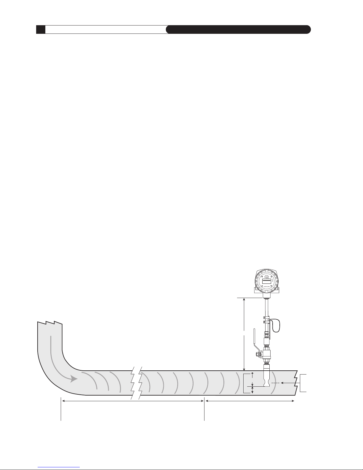
FLOW PROFILE AND INSTALLATION
CONSIDERATIONS
Insertion Flow Meters, although generally easier to
install that In-Line Flow Meters, require proper
installation, and a well developed flow profile, in
order to perform properly. Please refer to the section
on the following pages titled PROBE INSERTION
GUIDELINE DRAWING (page 14) and INSTALLA-
TION DEPTH CHART (page 15).
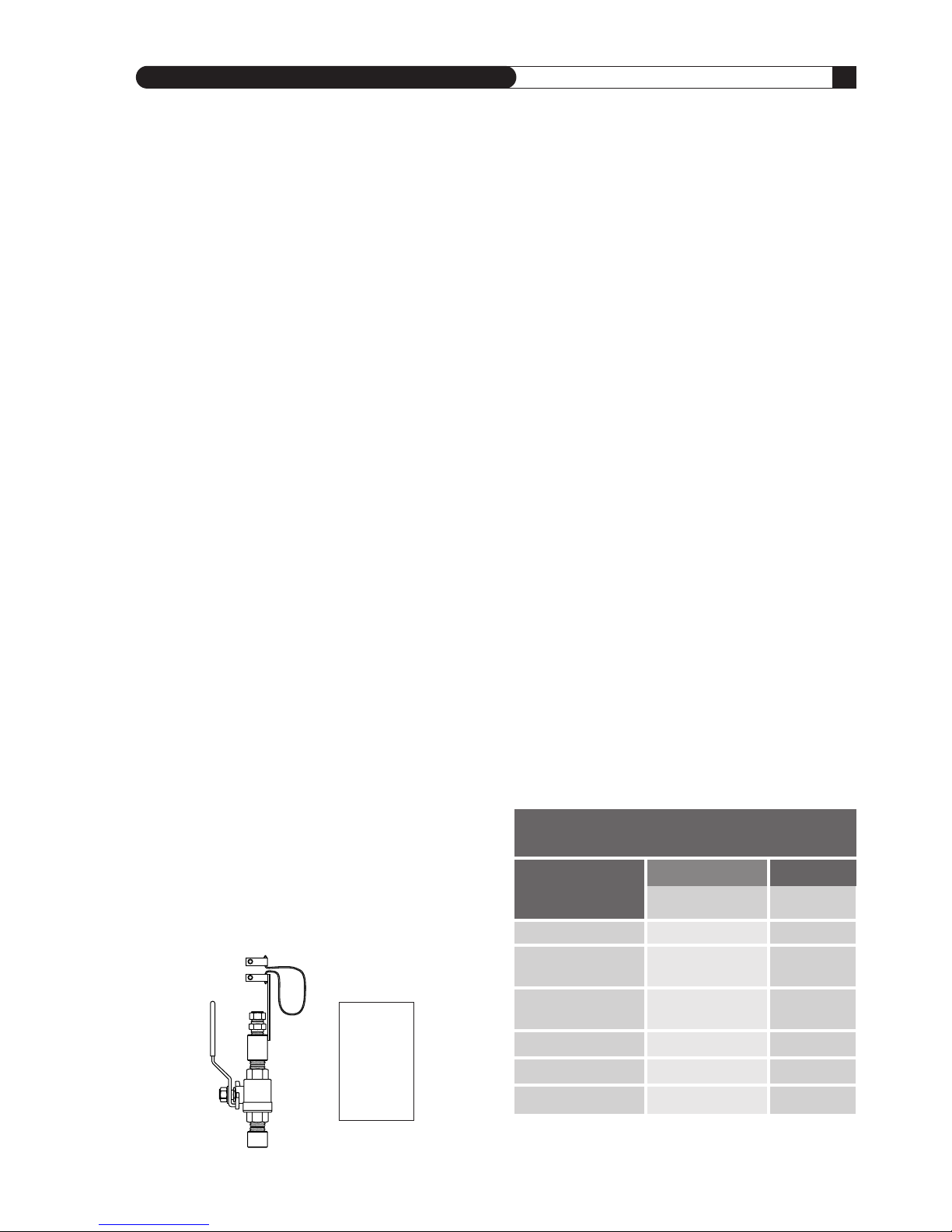
SAGE VALVE ASSEMBLY OPERATION
Valve assemblies (SVA05 and SVA05LP) are an op -
tional mounting hardware for Insertion Style Flow
Meters (see pages 38 and 39). They allow the removal
of insertion-style meters for service, cleaning, recali -
bration, relocation, etc. without the need to “shut-
down” your process. The probe insertion depth is
adjustable to permit sensor to be located at center
to optimize measurement accuracy. (Refer to PROBE
IN SERTION GUIDE LINE DRAWING and CHART, pages
14 & 15.) The ball valve will seal off leaks of the
process gas at the point of insertion after the probe
assembly has been removed. The assembly includes
a valve, threadolet, compression fitting with Teflon
ferrule, a cable restraint, and two collar clamps.
A threaded half coupling (3/4" FNPT) properly sized
to accom modate the isolation valve retractor assem-
bly must be fitted to the pipe/duct to which the
insertion probe will be inserted. Avoid T-Fittings
since they will disturb the flow profile, and effec-
tively reduce the measurement area. Direct thread-
ing together (or with necessary bushings) of the
retractor assembly may be required. In other cases,
the threadolet must be welded in place and a clear-
ance hole must be drilled through the pipe/ duct to
accept the probe assembly. If the pipe/duct is under
pressure during installation, a hot tap drill (not
available through Sage Metering) may be required.
FLOW CONDITIONING AND STRAIGHT RUN
Although a minimum of 15 pipe diameters of
upstream straight run is commonly recommended,
to absolutely assure that the flow profile is well
developed at the point of measurement, either use
Flow Conditioners (standard in Sage In-Line Flow
Meters, 1/2" and larger, and also available as assem-
blies for Insertion Flow Meters, see page 13), or
consider additional straight run. The Chart below
provides examples of the amount of straight run
that would virtually assure that there are no flow
disturbances at the point of measurement.
N O T E :
Detailed
Drawings
are shown
on pages
38 & 39.
Insertion Flow Meter Application
IMPO RTANCE OF FLO W CO NDITION ING
Reco mmen ded P ipe D iameter s Ups tream
One 90˚ Elbow
Two 90˚ Elbows
in the same plane
Two 90˚ Elbows
in different planes
4:1 Area Reduction
4:1 Area Expansion
Multiple Disturbance
3
5
9
3
10
TBD
1
This column applies to In-Line Flow Meters, which come standard with built-in Flow Conditioners, as well as Insertion Meters,
when provided with upstream Captive Flow Conditioners (see page 13).
D I S T U R B A N C E
15
20
At least 40
15
At least 30
To Be Determined
WITHOUT
FLOW CONDITIONING
Minimum Industry
Recommendation
WITH FLOW
CONDITIONING
1
Sage
Recommendation
S A G E M E T E R I N G , I N C .
O p e r a t i o n s a n d I n s t r u c t i o n M a n u a l
12
REV. 16-SIP/SRP
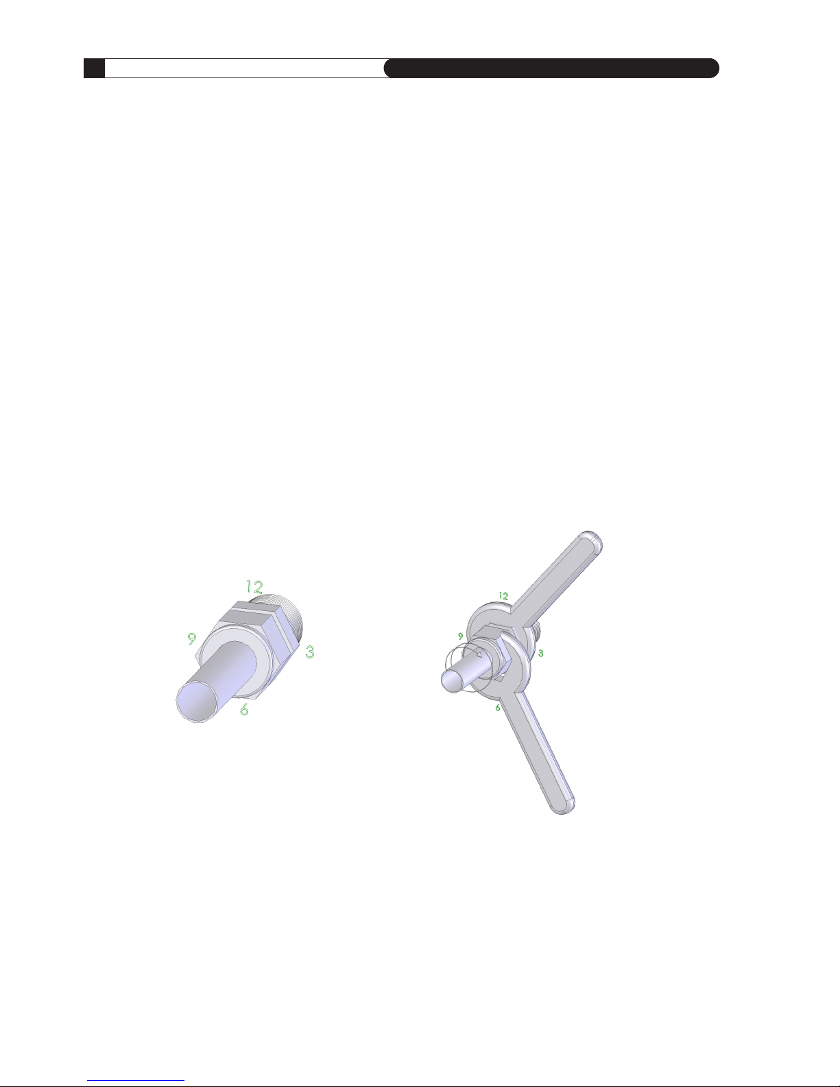
COMPRESSION FITTING OPERATION
A bored through tube fitting, properly sized to
accommodate an insertion probe’s particular OD,
can be provided by the user or purchased as an
option from Sage Metering (see page 38). Prior to
installation, a clearance hole to accommodate the
insertion probe assembly must be drilled in the
pipe/duct. A fitting (1/2" FNPT) is then welded in
place or threaded into the half-threadolet which has
been welded to the pipe/duct. The probe insertion
depth is adjustable to permit sensor to be located at
center, to optimize measurement accuracy. (Refer to
PROBE INSERTION GUIDELINE DRAWING and
CHART, pages 14 & 15.)
Insert the probe shaft tubing into the
compression fitting to the position indicated
in the Probe Insertion guidelines.
While holding the fitting body steady,
tighten the nut one and one-quar ter
turns to the 9 o’clock position.
INSTALLATION INSTRUCTIONS
1. Insert tubing into the tube fitting.
2. Make sure that the tubing is positioned properly
per the PROBE INSERTION GUIDELINE DRAW-
ING AND CHART, pages 14 & 15.
3. Due to the variations of tubing diameters, a
common starting point is desirable. Therefore,
tighten the nut until the tubing will not turn
by hand or move axially in the fitting.
4. Scribe the nut at the 6 o’clock position.
5. While holding fitting body steady, tighten the nut
1
1
⁄4 turns to the 9 o’clock position.
O p e r a t i o n s a n d I n s t r u c t i o n M a n u a l
13
S A G E M E T E R I N G , I N C .
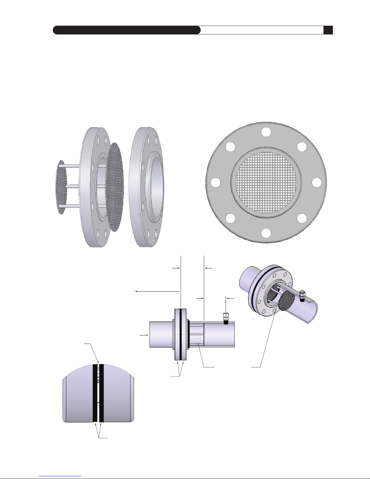
ANSI Class Flanges
(user supplied)
Largest of the
Two Perforated
Plates
Flow Conditioning
Assembly is
inserted here.
One Pipe
Diameter
FLOW
Gaskets
One Pipe
Diameter
Straight Run Requirement
from this Flange
CAPTIVE FLOW CONDITIONERS
Can Be Installed in Conjunction with Insertion Style Flow Meters
NOTE: The larger of the two perforated plates of the Sage
Flow Conditioning assembly is positioned between two flanges
and two gaskets as shown. The smaller of the two perforated
plates of the conditioner will freely slide into the application
pipe, facing downstream. The probe mounting hardware will be
placed one diameter downstream of the downstream plate.
Probe location must be one pipe ID diameter downstream of
Flow Conditioners or errors will occur.
Front View of one of the Conditioning Plates
IMPORTANT The location of the probe must be exactly one pipe ID diameter (i.e., 4” in a 4” pipe; 6” in
a 6” pipe, etc.) downstream of the Captive Flow Conditioning assembly. The Captive Flow Conditioners
are always designed to be separated by one pipe diameter. See drawing below. The probe location must
be one pipe ID diameter downstream of Flow Conditioner, or errors will occur.
Note: See table on page 11
(last Column) for Straight Run
Requirement
S A G E M E T E R I N G , I N C .
O p e r a t i o n s a n d I n s t r u c t i o n M a n u a l
14
REV. 16-SIP/SRP
PROBE INSERTION GUIDELINE DRAWING
1
Choose the longest straight-run section of pipe avail-
able to allow a uniform, well-developed flow profile.
A
llow for a minimum of 15 pipe diameters of straight
run upstream, and 5 diameters downstream, depend-
ing on the conditions. See chart on page 11. Note,
obstructions such as valves, blowers expanders and
PVC and HDPE pipes will require additional straight
run (contact factory for assistance). Avoid, if possible,
installations immediately downstream of bends, fans,
nozzles, heaters and especially valves, or anything
else installed in the line that may cause nonuniform
flow profiles and swirls. Otherwise signal output
errors could result, unless significantly more straight
run is provided, or in the absence of sufficient straight
run, Flow Conditioners (page 13) are in stalled (con-
tact Sage for assistance if needed). Refer to page 13 to
see the benefits of incorporating Flow Conditioners.
Insertion styles are available through Sage Metering,
Inc. with a standard 1/2" OD probe support assem-
bly; 3/4" is also available. Stan dard probe lengths
are 6", 12", 15", 18", 24", 30", 36" and 48". A common
method of mounting the probe assembly through
a pipe wall or duct (if ambient air) is with a compres-
sion fitting (STCF05). A Sage valve assembly (SVA05)
is useful and highly recommended for
pressurized applications or other gases,
such as Natural Gas. Flange mounting
is optionally available.
Sage insertion style flow meters can be assembled
and calibrated for use in virtually any size pipe or
duct (as small as 1”). Sage insertion flow meters
include a probe assembly that supports the sensing
element (a self-heated flow sensor and a tempera -
ture/reference sensor); a sensor drive circuit; micro -
pro cessor meter board, and trans mitter enclosure.
The probe assembly must be inserted into the correct
position in the pro cess gas flow conduit to allow the
gas to flow through the sensor “window” across the
sensor element. The “sensing point” or active part of
the sensor (0.5" from the end of the probe) should be
positioned as per the drawing below and the
Installation Depth Chart on page 15.
Installation Depth
The center of the pipe (assuming a well developed
turbulent flow profile) is fairly flat, and easy to
locate. See “Installation Depth Chart” on next page
to determine proper insertion depth.
Z
Y
X
4" PIPE SHOWN
LESS THAN IDEAL LOCATION
Contact Factory for Assistance
GOOD LOCATION
2,3
(See Installation Depth Chart for X and Y Dimension)
2. Probe should be inserted per Installation Depth Chart (see following page),
so sensors are in the center of the pipe.
3. The portion of the probe that remains outside of the pipe, is simply the factory
ordered probe length (i.e. “-15” = 15 inches) minus the “Y” dimension.
Center
of Pipe
PRIME
84˚F
1
3546
SCFM
4
67469670
SCF
88mW
1. SIP Industrial Meter shown in drawing. Note, probe is not bi-directional.
O p e r a t i o n s a n d I n s t r u c t i o n M a n u a l
15
S A G E M E T E R I N G , I N C .
I
NSTALLATION DEPTH CHART
Methods for Probe Insertion to Pipe Center
ME TH OD 1
Using charts below, select pipe size (column 1),
determine X. Insert probe until the end touches the
bottom of the pipe (ID), mark probe as it exits top
of fitting. Lift probe distance “X” and tighten com -
pression fitting.
ME TH OD 2
Using charts below1, select pipe size (column 1),
determine Y. Subtract Y from the factory supplied
probe length. That difference Z (see drawing on page
14) should be outside of the pipe, and is measured
from the bottom of the enclosure of the probe weld
to pipe OD.
PIPE SIZE OD ID XYPIPE AREA
1"
1.5" 1.900 1.500 .15" 1.56" 0.0123
2" 2.375 1.939 .35" 1.82" 0.0205
2.5" 2.875 2.323 .55" 2.07" 0.0294
3" 3.500 2.900 .80" 2.38" 0.0459
4" 4.500 3.826 1.30" 2.86" 0.0798
6" 6.625 5.761 2.25" 3.95" 0.1810
8" 8.625 7.625 3.25" 4.90" 0.3171
10" 10.750 9.750 4.25" 6.00" 0.5185
12" 12.750 11.374 5.13" 7.00" 0.7056
14" 14.000 12.500 5.70" 7.50" 0.8522
16" 16.000 14.312 6.60" 8.60" 1.1172
18" 18.000 16.124 7.50" 9.60" 1.4180
24" 24.000 21.562 10.25" 12.60" 2.5357
S C H E D U L E 4 0 P I P E
2
S C H E D U L E 8 0 P I P E
2
PIPE SIZE OD ID XYPIPE AREA
1"
1.5" 1.900 1.610 .20" 1.56" 0.0141
2" 2.375 2.067 .40" 1.82" 0.0233
2.5" 2.875 2.469 .60" 2.07" 0.0332
3" 3.500 3.068 .90" 2.38" 0.0513
4" 4.500 4.026 1.40" 2.86" 0.0884
6" 6.625 6.065 2.40" 3.95" 0.2006
8" 8.625 7.981 3.40" 4.90" 0.3474
10" 10.750 10.020 4.40" 6.00" 0.5476
12" 12.750 11.938 5.50" 7.00" 0.7773
14" 14.000 13.124 6.00" 7.50" 0.9394
16" 16.000 15.000 7.00" 8.60" 1.2272
18" 18.000 16.876 8.00" 9.60" 1.5533
24" 24.000 22.625 10.75" 12.60" 2.7919
C O N S U L T F A C T O R Y
C O N S U L T F A C T O R Y
1
For other Pipe Schedules, such as Schedule 10, contact Sage, however the Y dimension will
be the same for any Schedule Pipe
2
The 1" Pipe Size needs to have the Probe “Bottomed Out” (option “BOT"); the calibration
method for the 1
1
⁄2" Pipe is either as shown below, or with option “BOT”
S A G E M E T E R I N G , I N C .
O p e r a t i o n s a n d I n s t r u c t i o n M a n u a l
16
REV. 16-SIP/SRP
P
RIME
84˚F
1
3546
SCFM
467469670
SCF
88mW
P
RIME
8
4
˚
F
13546 SCFM
4
67469670
SCF
88mW
PRIME
84˚F
13546 SCFM
467469670
SCF
88mW
PRIME
8
4
˚
F
1
3546
S
CFM
4
67469670
S
CF
8
8mW
CONFIGURATION FOR UTILIZING FOUR (4) SAGE INSERTION MASS FLOW METERS FOR LARGE ROUND
PIPES OR DUCTS LARGER THAN 36" TO MINIMIZE EFFECTS OF VARYING FLOW PROFILES
(It is recommended that Factory be contacted to assist with applications of this nature)
The outputs of the four meters will be averaged
by customer’s PLC or other method to improve
overall accuracy in measuring the flow rate.
(For medium sized round pipes [18" to 36"],
two meters, on the opposite side of the same
diameter, may be sufficient [insert parallel to an
upstream 90 degree bend for optimal benefit.])
Note, in this configuration, each sensor needs
to be averaged.
1/2" NPT
User Entry
for Wiring
1/2" NPT
User Entry
for Wiring
3/4" NPT for
Probe Support
3/4" NPT for
Remote Cable
3/4" NPT for
Remote Cable
Large Duct or Stack Applications
O p e r a t i o n s a n d I n s t r u c t i o n M a n u a l
17
S A G E M E T E R I N G , I N C .
REV. 16-SIP/SRP
IN-LINE FLOW METERS
In-line mounting styles are available through Sage
Metering, Inc. in sizes from 1/4" pipe through 4"
pipe. Threaded male NPT ends are standard up to
2-1/2"; ANSI 150lb flanged ends are recommended
for 3" and 4" models. Contact the factory if optional
end mounting styles are required. Pipe sizes in excess
of 4" require the insertion style mass flow meter.
The in-line style flow meter assembly flow section is
typically specified to match the user’s flow conduit
and is plumbed directly in the flow line by thread-
LENGTH “L” SAME AS NON-FLANGED METER
(See table on page 27. For example, 1"x8" flow
body has an 8" length. The length will be the same
whether an NPT flow body, or whether flanged.
If a flanged flow body, the 8" dimension will be
a Face-to-Face dimension.)
FLOW CONDITIONING SCREENS FOR IN-LINE FLOW BODIES 1/2" AND UP
1
Screens shown
with NPT fitting.
1 Note, Flow conditioning is also available for Insertion Meter applications (see page 13)
ing, flanging, welding, etc. DO NOT USE REDUCERS.
It includes the sensing element (a self-heated flow
sensor and a temperature/reference sensor) mounted
directly in the specified flow section for exposure to
the process gas; a sensor drive circuit; microprocessor
meter board, and transmitter enclosure.
All in-line Flow Meters, 1/2" and up have built-in
Flow Conditioners. See Table (page 10) for Upstream
Straight run requirements. Note, the 1/4" and 3/8"
do not have Flow Conditioners and thus require
more straight run.
In-Line Flow Meter Application
S A G E M E T E R I N G , I N C .
O p e r a t i o n s a n d I n s t r u c t i o n M a n u a l
18
REV. 16-SIP/SRP
Prime Integral (Series SIP)
SEE “WIRING” ON PAGE 10 FOR INSTRUCTIONS ON HOW TO REMOVE REAR LID;
SEE FOLLOWING PAGES FOR TERMINAL HOOKUP
1 RED AC1 COM 1
2
S1 AC2 B + 2
3
RED SPARE A – 3
4
WHITE
4-20mA PWR
4
5
S2 4-20mA 5
6
WHITE VDC GND 6
A B C
24 VDC
P
ULSE
VDC IN
+
VDC GND
–
INTEGRAL
INSIDE COVER VIEW INSIDE BODY VIEW
1/2" NPT
User Entry
for Wiring
3/4" NPT for
Probe Support
NO CUSTOMER ACCESS
DO NOT OPEN THIS SIDE
DISPLAY SIDE
1/2" NPT
View Entry
(ONE ON EACH SIDE)
FLOW
TERMINAL BLOCK SIDE
O p e r a t i o n s a n d I n s t r u c t i o n M a n u a l
19
S A G E M E T E R I N G , I N C .
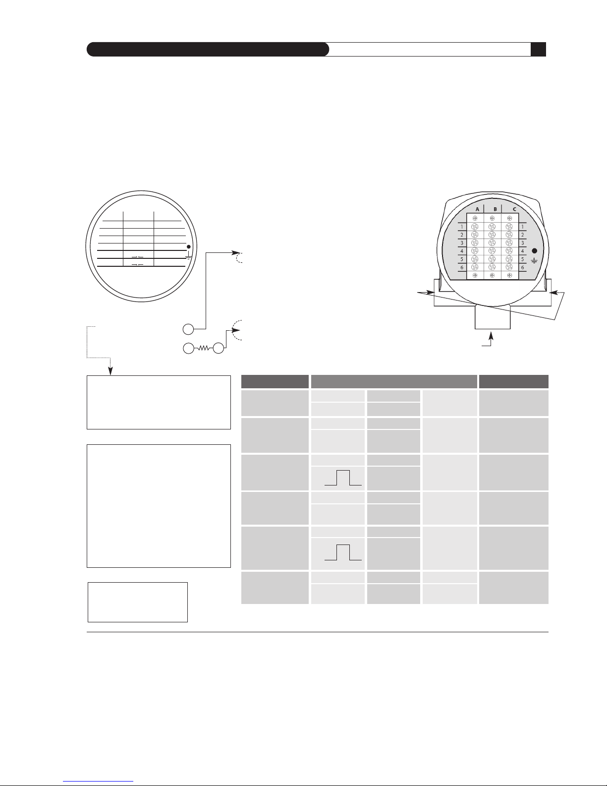
24 VDC Prime Integral Terminals (Series SIP)
(APPROVED FOR HAZARDOUS SERVICE6)
1 RED AC1 COM 1
2
S1 AC2 B +
2
3
RED SPARE A –
3
4 WHITE
4-20mA PWR
4
5
S2 4-20mA 5
6
WHITE VDC GND
6
A B C
2
4 VDC
PULSE
VDC IN
+
VDC GND
–
I
NTEGRAL
INSIDE COVER VIEW
NOTE: The Sage Prime
draws 2.4 watts maximum
(i.e. ≅ 100ma @24VDC)
–
+
C
U STO ME R
R ET UR N
E
X TE RN AL LY P OW ER ED
4 –2 0 mA BY C US TO ME R
+
*
DESCRIPTION TERMINALS NOTES
DC Input Power: B5 B6
24 VDC
7,8
+ VDC – VDC GND
Internally Powered: C5 C6 Do not remove
4-20 mA
4-20 mA Return
any Jumpers
SIGNAL DRIVE
Internally Powered: C4 C6 Do not remove
Pulsed Output
GND
any Jumpers
Externally Powered: C5 B4 Remove B4 & B5
4-20 mA
4-20 mA 4-20 mA
Jumper
SIGNAL DRIVE EX TERNAL SOURCE
Externally Powered9: C4 B3 Remove B4 & B5
Pulsed Output
JUNCTION FOR
Jumper and Connect
PULSE RETURN C4 Resistive Jumper
to B3
MODBUS C2 C3 C1 Modbus Ground
10
RS485(+) RS485(–) MODBUS GROUND
(REQ’D)
*B4 and B5 JUMPER
Remove jumper for Externally Sourced 4-20
mA. In this mode, user supplies 9-27 Volts to
externally power the 4-20 mA loop, and the
4-20 mA loop becomes optically isolated.
1 Specify the Sage Prime PLUS option in order to have the Modbus Ground (Terminal C1, COM) isolated
from the 24 VDC Sage Power Supply Ground (Terminal B6). All other features of Prime PLUS are
identical to the standard Sage Prime, except other voltage available. (See footnote 8)
2 It is important to connect the Ground when using Modbus communications, or ground loop problems
may develop. Improper wiring can also damage internal circuitry
3 Note, if customer externally powers the 4-20 mA by removing the jumper, the Pulse voltage output
is also effected: The voltage output of the Pulse will follow the customer power (i.e. 24 VDC external
power will result in a 24 VDC Pulse [maximum of 50 mA]; 12 VDC external power will result in a
12 VDC Pulse)
4 Pulse width 250 msec default (adjustable with Addresser software)
5 Using Sage Addresser, a Low Flow Cutoff (LFC), commonly referred to as Min Cutoff or Zero Cutoff
can be entered into the FLOW MIN Functions. In Versions 1.82 or higher, the Low Flow Cutoff and
the 4-20 mA Scaling are independent of each other. For example: A Low Flow Cutoff (LFC) of
10 SCFM on a Meter with a Full Scale of 100 SCFM will report 0 on the Display and 4 mA on the
output. The output will remain at 4 mA until the LFC is exceeded: (ie: 25 SCFM=8 mA). Thus the
4 mA will always be zero based
6 Class I, Div 2, Groups B,C,D,T4 and ATEX Ex na IIC T4
7 24 VDC ±10%
8 Other DC voltages (5 VDC, 12 VDC, 48 VDC) available on Prime PLUS. Contact Sage
9 Assumes the 4-20 mA is Externally Powered
10 Modbus Ground becomes isolated from the B6 Power Supply Ground only on Prime PLUS version
(specify “PLUS”)
INSIDE BODY VIEW
1/2" NPT
User Entry
for Wiring
3/4" NPT for
Remote Cable
(on Remote Style SRP)
**
**Note, Flow Meter is supplied with a 10K
(1/2 watt) metal film resistor (Resistive
Jumper) connected across Terminals C4 and
C6. For externally powered operation, in
addition to removing B4 & B5 Jumpers, it
is necessary to connect C4 Resistive Jumper
to Terminal B3 instead of C6. Note, B3 must
be connected to the External Sources common in order to enable the optically isolated
pulse output. In this mode, Pulse Output is
optically isolated. Pulsed Output voltage will
depend on customer source voltage. Use
Sage Resistive Jumper only!
**
A1 – RED – VELOCITY SENSOR WIRE (HEATED ELEMENT)
A2 – NO WIRE
A3 – RED – VELOCITY SENSOR WIRE (HEATED ELEMENT)
A4 – WHITE – TEMPERATURE SENSOR WIRE
A5 – NO WIRE
A6 – WHITE – TEMPERATURE SENSOR WIRE
B3 – JUNCTION FOR ISOLATED PULSE
B4 – 4-20 mA RETURN (–) AND PULSE SOURCE
B5 – VDC IN – VOLTAGE DC – POSITIVE (+)
B6 – VDC GND – VOLTAGE DC – GROUND (–)
1
C1 – COM – RS485 MODBUS GROUND
1,2
C2 – B(+)–RS485_D1
C3 – A(–)–RS485_D0
C4 – 24 VDC PULSE – 0 TO 24 VDC PULSE OUTPUT
3,4
C5 – 4-20 mA – 4 TO 20 mA SIGNAL DRIVE
5
C6 – VDC GND – VOLTAGE DC – GROUND (–)
24
O
24
O
S A G E M E T E R I N G , I N C .
O p e r a t i o n s a n d I n s t r u c t i o n M a n u a l
20
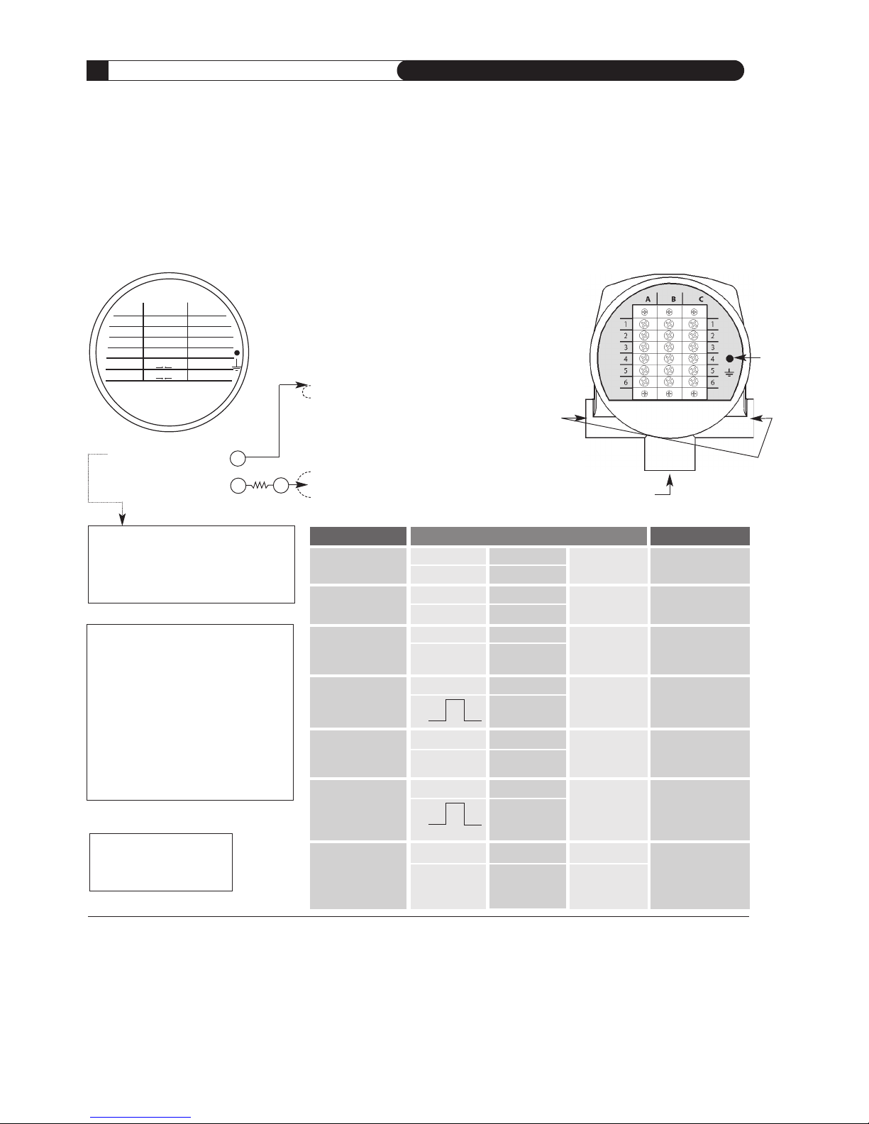
AC Powered Prime Integral Terminals (Series SIP)
6
1 RED AC1 COM 1
2
S1 AC2 B +
2
3
RED SPARE A –
3
4 WHITE
4-20mA PWR
4
5
S2 4-20mA 5
6
WHITE VDC GND
6
A B C
2
4 VDC
PULSE
VDC IN
+
VDC GND
–
I
NTEGRAL
INSIDE COVER VIEW
NOTE: The Sage Prime
draws 2.4 watts maximum
(i.e. ≅ 100ma @24VDC)
–
+
C US TO ME R
R ET UR N
E
X TE RN AL LY P OW ER ED
4
– 20 m A B Y CU ST OM ER
+
*B4 and B5 JUMPER
Remove jumper for Externally Sourced 4-20
mA. In this mode, user supplies 9-27 Volts to
externally power the 4-20 mA loop, and the
4-20 mA loop becomes optically isolated.
1 Specify the Sage Prime PLUS option in order to have the Modbus Ground (Terminal C1, COM) isolated
from the 24 VDC Sage Power Supply Ground (Terminal B6). All other features of Prime PLUS are
identical to the standard Sage Prime, except other voltage available. (See footnote 8)
2 It is important to connect the Ground when using Modbus communications, or ground loop problems
may develop. Improper wiring can also damage internal circuitry
3 Note, if customer externally powers the 4-20 mA by removing the jumper, the Pulse voltage output
is also effected: The voltage output of the Pulse will follow the customer power (i.e. 24 VDC external
power will result in a 24 VDC Pulse [maximum of 50 mA]; 12 VDC external power will result in a
12 VDC Pulse)
4 Pulse width 250 msec default (adjustable with Addresser software)
5 Using Sage Addresser, a Low Flow Cutoff (LFC), commonly referred to as Min Cutoff or Zero Cutoff
can be entered into the FLOW MIN Functions. In Versions 1.82 or higher, the Low Flow Cutoff and
the 4-20 mA Scaling are independent of each other. For example: A Low Flow Cutoff (LFC) of
10 SCFM on a Meter with a Full Scale of 100 SCFM will report 0 on the Display and 4 mA on the
output. The output will remain at 4 mA until the LFC is exceeded: (ie: 25 SCFM=8 mA). Thus the
4 mA will always be zero based
6 This version does not have Hazard Approvals
7 24 VDC ±10%
8 Other DC voltages (5 VDC, 12 VDC, 48 VDC) available on Prime PLUS. Contact Sage
9 Assumes the 4-20 mA is Externally Powered
10 Modbus Ground becomes isolated from the B6 Power Supply Ground only on Prime PLUS version
(specify “PLUS”)
INSIDE BODY VIEW
1/2" NPT
User Entry
for Wiring
3/4" NPT for
Remote Cable
(ON REMOTE STYLE SRP)
Grounding
Lug
**
**
A1 – RED – VELOCITY SENSOR WIRE (HEATED ELEMENT)
A2 – NO WIRE
A3 – RED – VELOCITY SENSOR WIRE (HEATED ELEMENT)
A4 – WHITE – TEMPERATURE SENSOR WIRE
A5 – NO WIRE
A6 – WHITE – TEMPERATURE SENSOR WIRE
B1 – AC1 – AC VOLTAGE
B2 – AC2 – AC VOLTAGE
B3 – JUNCTION FOR ISOLATED PULSE
B4 – 4-20 mA RETURN (–) AND PULSE SOURCE
B5 – VDC IN – VOLTAGE DC – POSITIVE (+)
B6 – VDC GND – VOLTAGE DC – GROUND (–)
1
C1 – COM – RS485 MODBUS GROUND
1,2
C2 – B(+)–RS485_D1
C3 – A(–)–RS485_D0
C4 – 24 VDC PULSE – 0 TO 24 VDC PULSE OUTPUT
3,4
C5 – 4-20 mA – 4 TO 20 mA SIGNAL DRIVE
5
C6 – VDC GND – VOLTAGE DC – GROUND (–)
24
O
24
O
DESCRIPTION TERMINALS NOTES
AC Input Power: B1 B2 Connect Ground Wire
115 VAC/230 VAC
AC1 AC2
to Grounding Lug
DC Input Power: B5 B6
24 VDC
7,8
+ VDC – VDC GND
Internally Powered: C5 C6 Do not remove
4-20 mA
4-20 mA Return
any Jumpers
SIGNAL DRIVE
Internally Powered: C4 C6 Do not remove
Pulsed Output
GND
any Jumpers
Externally Powered: C5 B4 Remove B4 & B5
4-20 mA
4-20 mA 4-20 mA
Jumper
SIGNAL DRIVE EX TERNAL SOURCE
Externally Powered9: C4 B3 Remove B4 & B5
Pulsed Output
JUNCTION FOR
Jumper and Connect
PULSE RETURN C4 Resistive Jumper
to B3
MODBUS C2 C3 C1 Modbus Ground
10
RS485(+) RS485(–) MODBUS GROUND
(REQ’D)
*
**Note, Flow Meter is supplied with a 10K
(1/2 watt) metal film resistor (Resistive
Jumper) connected across Terminals C4 and
C6. For externally powered operation, in
addition to removing B4 & B5 Jumpers, it
is necessary to connect C4 Resistive Jumper
to Terminal B3 instead of C6. Note, B3 must
be connected to the External Sources common in order to enable the optically isolated
pulse output. In this mode, Pulse Output is
optically isolated. Pulsed Output voltage will
depend on customer source voltage. Use
Sage Resistive Jumper only!
O p e r a t i o n s a n d I n s t r u c t i o n M a n u a l
21
S A G E M E T E R I N G , I N C .
REV. 16-SIP/SRP
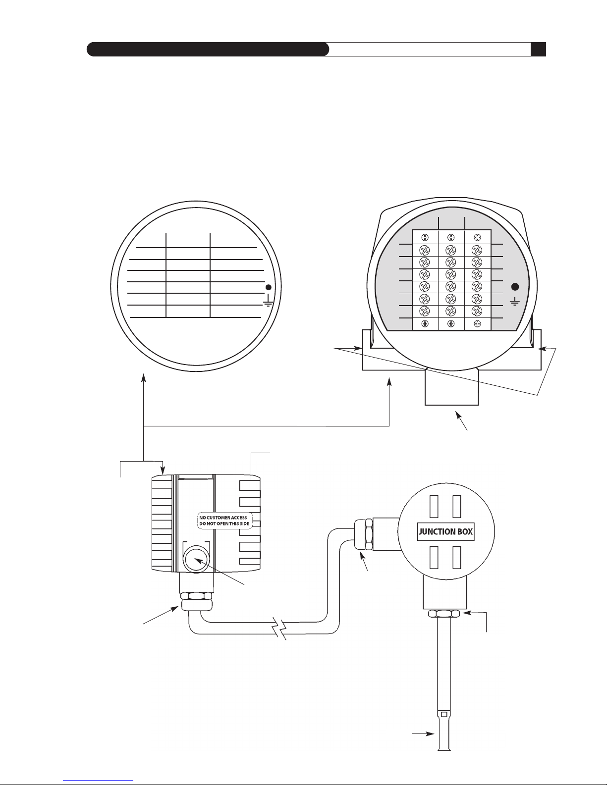
Prime Remote (Series SRP)
SEE “WIRING” ON PAGE 10 FOR INSTRUCTIONS ON HOW TO REMOVE REAR LID;
SEE FOLLOWING PAGES FOR TERMINAL HOOKUP
REMOTE
1
RED AC1 COM
1
2
GREEN AC2 B +
2
3
BLUE SPARE A –
3
4
WHITE
4-20mA PWR 24 VDC PULSE
4
5
BLACK VDC IN 4-20mA
5
6
ORANGE VDC GND VDC GND
6
A B C
1
2
3
4
5
6
1
2
3
4
5
6
A B C
INSIDE COVER VIEW INSIDE BODY VIEW
DISPLAY SIDE
1/2" NPT
User Entry
for Wiring
3/4" NPT for
Remote Cable
(ON REMOTE STYLE SRP)
3/4" NPT for
Remote Cable
3/4" NPT for
Probe Support
Junction Box
contains no
electronics,
just terminals
1/2" NPT
User Entry for Wiring
(ONE ON EACH SIDE)
FLOW
TERMINAL
BLOCK SIDE
3/4" NPT for
Remote Cable
 Loading...