

Page 1
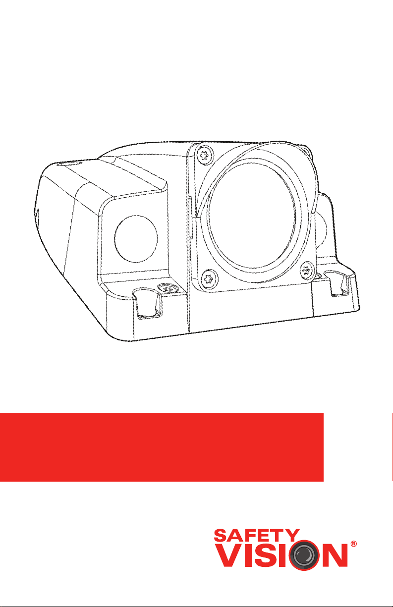
48 SERIES IP CAMERA
USER GUIDE
Page 2

48 SERIES IP CAMERA
Important Notices
Title: 48 series IP Camera User Guide
Document Version: 1
Revision: 1
Safety Vision attempts to provide information contained in this
manual based on the latest product information available at the
time of publication. However, because of Safety Vision’s policy of
continual product improvement, Safety Vision reserves the right to
amend the information in this document at any time without prior
notice.
This material is condential and the property of Safety Vision. It
is shared with your company for the sole purpose of helping you
with the operation of the described equipment.
Safety Vision makes no warranty of any kind with regard to this
material, including, but not limited to, the implied warranties of
merchantability and tness for a particular purpose. Safety Vision
shall not be liable for errors contained herein or for incidental
or consequential damages in connection with the furnishing,
performance, or use of this material.
Safety Vision expressly disclaims all responsibility and liability
for the installation, use, performance, maintenance, and support
of third-party products. Customers are advised to make their
independent evaluation of such products.
No part of this document may be photocopied, reproduced, or
translated to another language without the prior written consent
of Safety Vision.
Safety Vision® is a registered trademark of Safety Vision, LLC. All
other products or name brands mentioned in this document are
trademarks of their respective owners. For more information
about Safety Vision and its products, go to www.safetyvision.com
or call 800-880-8855.
Page 3

1
48 SERIES IP CAMERA
Contents
Features 2
Parts Included 2
Overview 3
Cable Descriptions 4
Installation
Before you start 6
Memory Card 7
Camera 8
Connecting the Camera Cables 9
Connect Alarm Input/Output Cables 10
Network Cable Waterproof Jacket (Optional) 12
Conguration
Camera Initialization 14
Modify IP Address 15
Accessing via Web Browser 16
Appendix A: Specications 17
Appendix B: Dimensions 18
FCC Compliance Statement 19
Page 4

48 SERIES IP CAMERA
Features
• 3-axis gimbal provides exible mounting opportunities
• IP69K rating resists debris and sustained water jets
• Long distance IR illuminators perfect for exterior environments
Parts Included
• 48 Series IP Camera with Lens Cover
• Quick Start Guide
• Mounting Template
• Waterproof Connector
• Screw Package
• Wrench (Optional)
2
• CD
Page 5
3
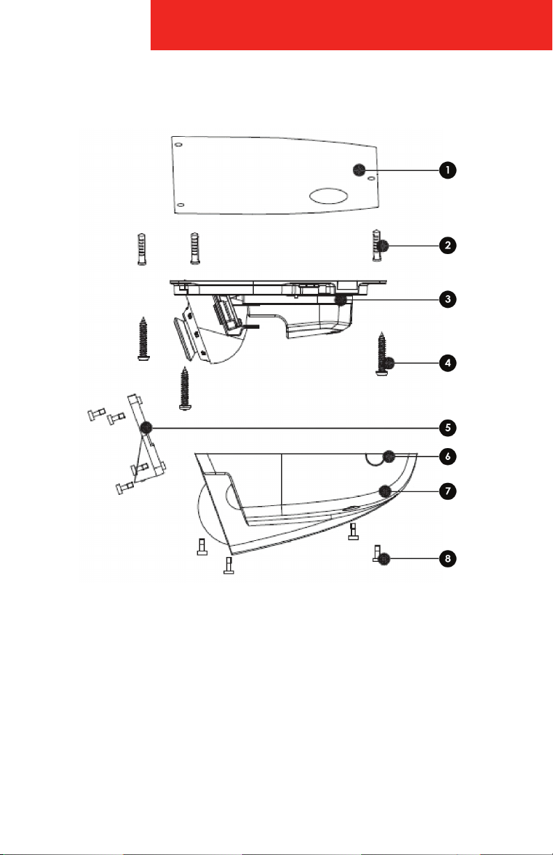
Overview
48 SERIES IP CAMERA
1 - Gasket
2 - Fastener Anchors
3 - Camera Base
4 - Self-tapping Screws
5 - Lens Cover
6 - Side Cable Exit
7 - Camera Cover
8 - Locking Screw
Page 6
48 SERIES IP CAMERA
Cable Descriptions
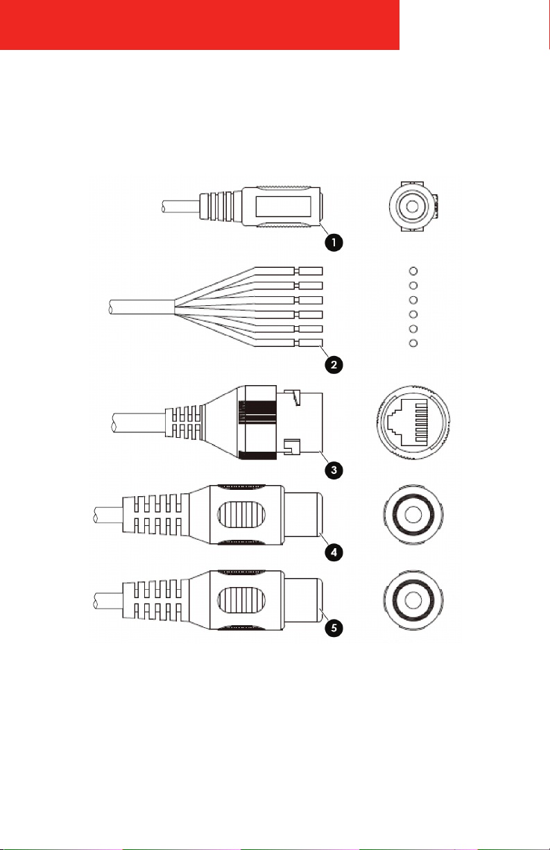
The following describes the different connectors that may be encountered on this
camera series.
4
Page 7

5
48 SERIES IP CAMERA
1 - Power Input: Input power, connect to DC 12V power, and please be sure
to power the device according to the instruction of device label.
2 - Alarm I/O: Input and output wires for alarm. Refer to “Alarm I/O” table for
details.
3 - Network port: Network data transmission and Power over Ethernet (PoE)
power supply.
4 - Audio Out: Output audio signal to the speakers and other devices.
5 - Audio In: Input audio signal, receive analog audio signal from other
devices.
ALARM I/O CONNECTIONS
COLOR PORT NAME DESCRIPTION
Blue ALARM_IN1 Alarm input port 1, receive on-o signal from external alarm source.
Brown ALARM_OUT1 Alarm output port 1, output alarm signal to alarm device.
Green ALARM_OUT_GND1 GND 1
White ALARM_IN2 Alarm input port 2, receive on- o signal from exter nal alarm source.
Red ALARM_OUT2 Alarm output por t 2, output alar m signal to alarm device.
Black ALARM_OUT_GND2 GND 2
Page 8

48 SERIES IP CAMERA
Installation
Before you start
• Ensure the camera is in good condition and all accessories
were included.
• Ensure the mounting surface is sucient to support the weight
of the camera.
• Implement this step when it needs to use microSD card and there is a
SD card slot for the device.
• Turn o the device power before installing microSD card.
• Dust or grease on the dome may cause IR reections in the image.
Do not remove the dome cover film until the installation
is complete.
• Ensure there are no reective surfaces close to the camera lens.
• The foam ring around the lens must be seated ush against the inner
surface of the dome to isolate the lens from the IRs.
6
Page 9
7
48 SERIES IP CAMERA
Memory Card
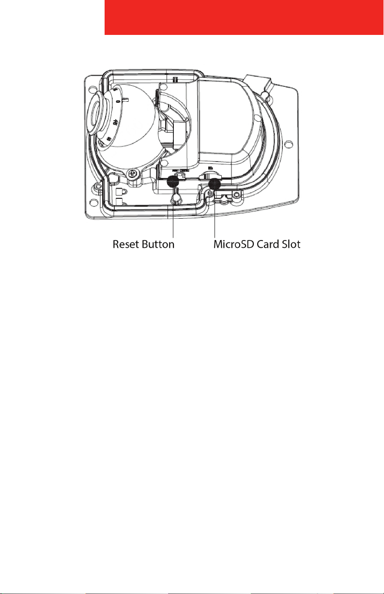
The 48 series IP cameras supports microSD card for local storage. Use the
following procedure to mount the memory card.
1. Remove camera dome cover.
Using a T15 TORX™, loosen the 4 locking screws and remove
dome cover.
2. Release microSD card.
Lightly push down on the microSD card until a “click” is felt, then allow it
to spring out of the slot.
3. The microSD card partly ejects.
4. Pull the microSD card straight out.
Reinsert the microSD card in the same manner: push card straight in until a “click”
is felt, then release.
NOTE: Press the Reset Button for approximately 10 seconds while the camera is
powering on to restore the default settings.
Page 10

48 SERIES IP CAMERA
Camera
1. Clean the area where the camera is to be installed.
2. Mark mounting and cable exit hole locations.
Use the included adhesive template and mark the three mounting screw
holes and cable exit hole in the desired mounting location.
3. Drill cable exit hole.
Use a hole saw or appropriate drill bit to drill a 1.75” hole for the cable
exit, as shown on the template.
4. Drill anchor holes.
Use an appropriate drill bit to drill three fastener anchor holes where
marked. Insert the anchors into the mounting holes and lock them rmly.
5. Remove camera cover.
Using a T15 TORX™, loosen the 4 locking screws and remove camera
cover.
8
6. Position gasket on mounting surface.
Align the gasket holes with the three fastener anchors on the mounting
surface and place camera base on gasket, threading the cable through
the 1.75” hole. Place three self-tapping screws into the three anchors and
securely tighten them.
WARN ING : Do not over tighten the mounting screws as it may bend or break
the base plate.
IMPORTANT: After installing the gasket and camera base, the cable channel
MUST be sealed in order to prevent water intrusion into the vehicle. To seal
the cable channel, squeeze silicone into the cable channel on the base. It is
also recommended to put a bead of silicone around the camera base to seal
it as well.
7. Connect 48 series camera to NVR.
Connect the 48 series camera to one of the camera inputs on the NVR.
Page 11

9
8. Configure 48 series camera.
Using a laptop, access the camera’s live view as described in the
Configuration section.
9. Adjust camera angle and field of view.
Use a small Phillips head screwdriver (pan rotation) and a T15 TORX (tilt
rotation) to loosen the screws on the camera gimbal to adjust the camera
angle to the desired field of view. Once completed, tighten the screws in
place.
10. Secure camera dome cover.
Using a T15 TORX™, tighten the 4 locking screws securely to the camera
base to ensure the camera is waterproof.
WARN ING : Do not over tighten the camera housing torque screws because
they can be stripped or broken.
48 SERIES IP CAMERA
Connecting the Camera Cables
1. Connect corresponding power, audio cable to external cable. Use
insulated tape to wrap the connection and make it waterproof.
2. Connect alarm input and output terminal to external cable according to
Connect Alarm Input/Output Port. Use insulated tape to wrap connection
to make it waterproof.
3. Connect network cable to corresponding network port of the device
cable according to Network Cable Waterproof Jacket (Optional).
Page 12
48 SERIES IP CAMERA
Connect Alarm Input/Output Cables
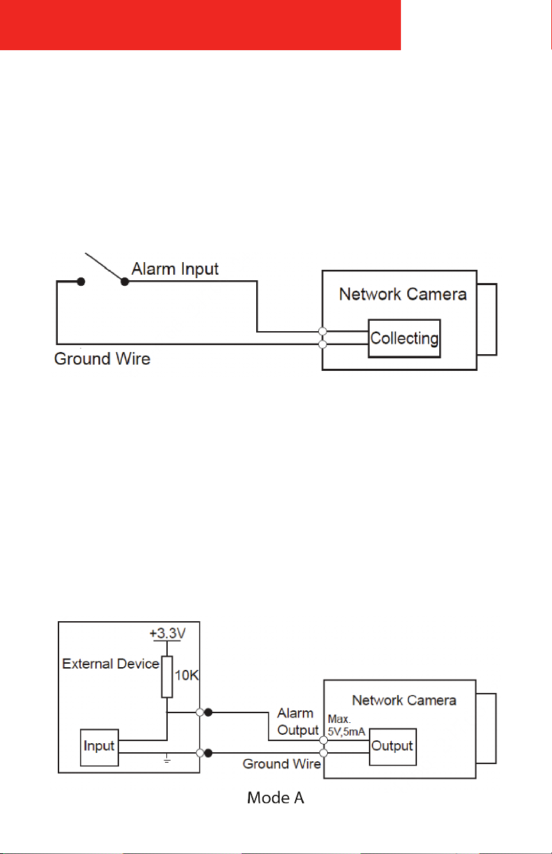
1. Connect alarm input device to the alarm input of I/O port.
When the input signal is idle or grounded, the device can collect the
dierent statuses of the alarm input port. When the input signal is
connected to 3.3V or it is idle, the device collects the status “1”. When the
input signal is grounded, the device collects the status “0”.
2. Connect alarm output device to the alarm output of I/O cable, alarm
output is an open circuit output which connects a 10K resistor to 3.3V
externally.
Mode A: Level application. Alarm output high and low level, alarm output
is OC; it needs to increase pull-up resistance externally to work normally.
Max external pull-up level is 12V, max port current is 300mA (peak). After
external pull-up resistance is increased, the default output signal is high
level (external pull-up voltage), and it switches to low level when there is
alarm output.
10
Page 13
11
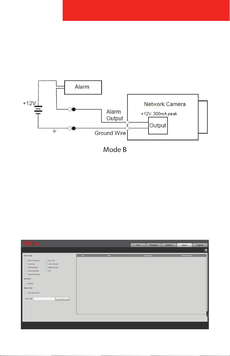
Mode B: Switch application. Alarm output is used to drive external circuit,
max voltage is 12V and max current is 300mA (peak), it is recommended
to add a relay when it exceeds the value.
3. Log into web interface, make corresponding settings upon alarm input
and output on the interface of alarm setup.
48 SERIES IP CAMERA
• Alarm input of web is corresponding to the alarm input of I/O port cable.
It is to set corresponding NO, NC input according to the high and low level
signal generated when the alarm is triggered.
• Set alarm output on the web, alarm output is corresponding to the alarm
output end, which is the alarm output port of the I/O port cable.
Page 14
48 SERIES IP CAMERA
Network Cable Waterproof Jacket (Optional)
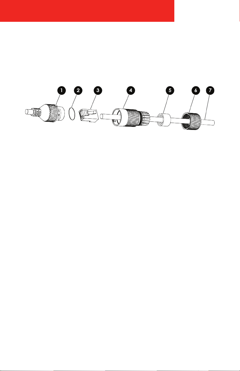
If the camera is installed outdoors, a waterproof jacket on the connection is
required for water resistance.
12
1 - Camera’s Network Interface
Socket
2 - O-Type Gasket
3 - Network Plug
4 - Waterproof Endcap
5 - Waterproof Rubber Gasket
6 - Lock Nut
7 - Network Cable from Router/
Switch
Page 15
13
48 SERIES IP CAMERA
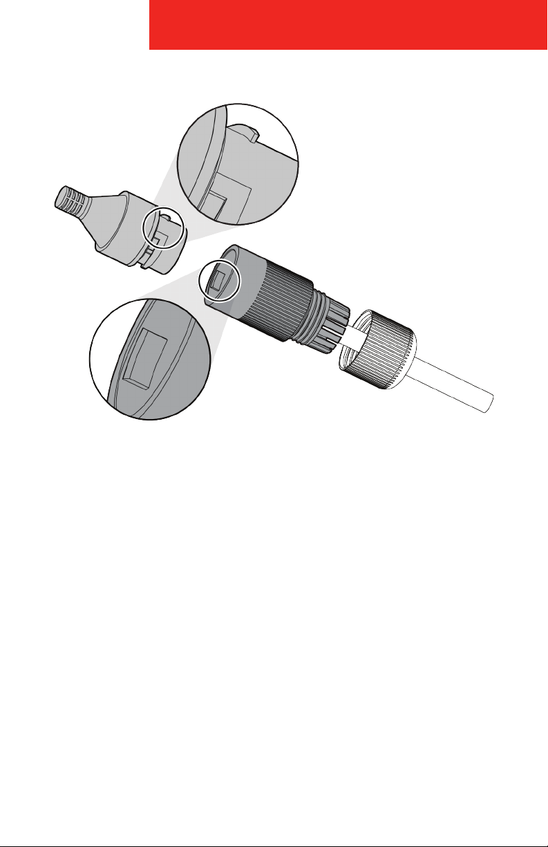
1. Feed the camera network cable through the lock nut, waterproof rubber
gasket (the rubber gasket inset ridge must face the waterproof endcap),
and the waterproof endcap in order.
2. Crimp an RJ-45 network plug onto the end of the cable, taking care to
insert the twisted pairs of wires in correct order.
3. Place the O-type gasket onto the end of the camera’s network interface
socket.
4. Insert the network plug into the camera’s network interface
socket.
5. Insert the waterproof rubber gasket into the waterproof endcap, and
secure the lock nut with the waterproof endcap.
6. Align the snap on the waterproof endcap with the notch on the camera’s
network interface socket, and then secure the waterproof endcap to the
camera’s network interface socket to nish the installation.
Page 16
48 SERIES IP CAMERA
14
Configuration
The 48 series camera can be configured through the Quick Configuration
Tool software which must be accessed with a PC. The camera will need to be
configured if it is the first time the camera is used or if it has been restored to
factory default settings.
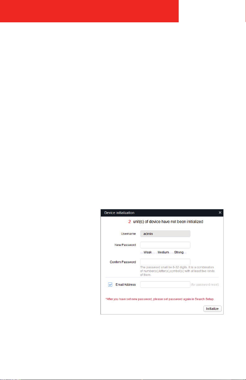
Camera Initialization
1. Connect the PC to the NVR’s Ethernet LAN RJ-45 port with a standard
Ethernet cable.
2. Ensure the NVR and PC are receiving power and have started up.
3. Run Quick Configuration Tool.
4. Click IP to modify the IP address, click Search Setting, and the system will
display the Setting dialog box.
5. Set the device network segment, login user name and password, and
then click OK.
6. Select the cameras
which need
conguration and
click Initialization.
The system will
display the Device
Initialization window
will appear.
7. Click Initialization,
the system will begin
to congure the
camera.
8. Click OK to complete
device conguration.
Page 17
15
48 SERIES IP CAMERA
Modify IP Address
1. Connect the PC to the NVR’s Ethernet LAN RJ-45 port with a standard
Ethernet cable.
2. Ensure the NVR and PC are receiving power and have started up.
3. Run Quick Configuration Tool.
4. Click IP to modify the IP address, click Search Setting, and the system will
display the Setting dialog box.
5. Set the device network segment, login user name and password, and
then click OK.
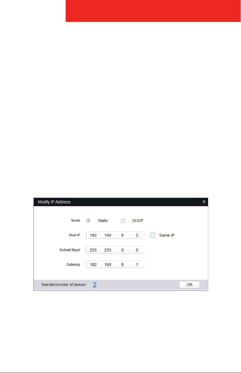
6. Select the camera IP addresses’ that need to be modied and click Batch
Modify IP. The system will display the Modify IP Address dialog box.
7. Set the mode as Static, and enter the planned start IP, subnet mask and
gateway.
NOTE: Set the mode as DHCP when there is DHCP server in the network, the
device will automatically acquire IP address from the DHCP server.
8. Click OK to complete device conguration.
Page 18
48 SERIES IP CAMERA
Accessing via Web Browser
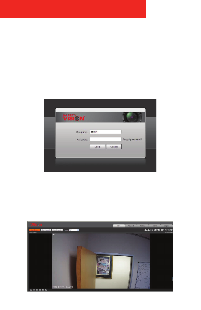
1. In a web browser, navigate to the camera’s IP address.
The default IP address is 192.168.1.108.
The default login is:
Username: admin
Password: admin
Enter username and password, click Login.
16
2. Install any plug-ins you are prompted to install. The main interface will be
shown after all plug-ins are installed.
3. The browser may be required to restart, requiring you to login again.
Page 19

17
48 SERIES IP CAMERA
Appendix A: Specifications
IMAGE SENSOR
1/3” 4MP progressive scan CMOS
FOCAL LENGTH
2.8mm (3.6mm, 6.0mm optional)
FIELD OF VIEW
H: 104° (2.8 mm), 83° (3.6m m), 55° (6.0 mm)
V: 55° (2. 8mm), 45° (3.6mm), 31° (6.0m m)
RESOLUTION
4M (2688 × 1520), 3M (2304 × 1296),
1080p (1920 × 10 80), 1.3M (1280 × 960),
720p (1280 × 720), D1 (704 × 576/704 × 480),
VGA (640 × 480), CIF (352 × 288/352 × 240)
FRAME RATE
4M (1~25/30 fps), D1 (1~25/30 fps), 720p
(1~2 5/3 0f ps )
DI GITAL ZOOM
16x
VIDEO COMPRESSION
H.265+/H.265/H.264+/H.264
ELECTRONIC SHUTTER SPEED
Auto/Manual, 1/3~1/100000 sec
IMAGE SETTING
Back Light Compensation, Auto White
Balance, Auto Gain Control, Flip,
Mirror
INFRARED ILLUMINATORS
2
MINIMUM ILLUMINATION
.08 lux (0 lux with IRs)
IP RATING
IP69K
IMPACT RATING
IK10
POWER REQUIREMENT
12V DC / PoE
POWER CONSUMPTION
<6.5W
OP ERATING TE MPERATURE
-40° F ~ 158° F (-40° C ~ 70° C )
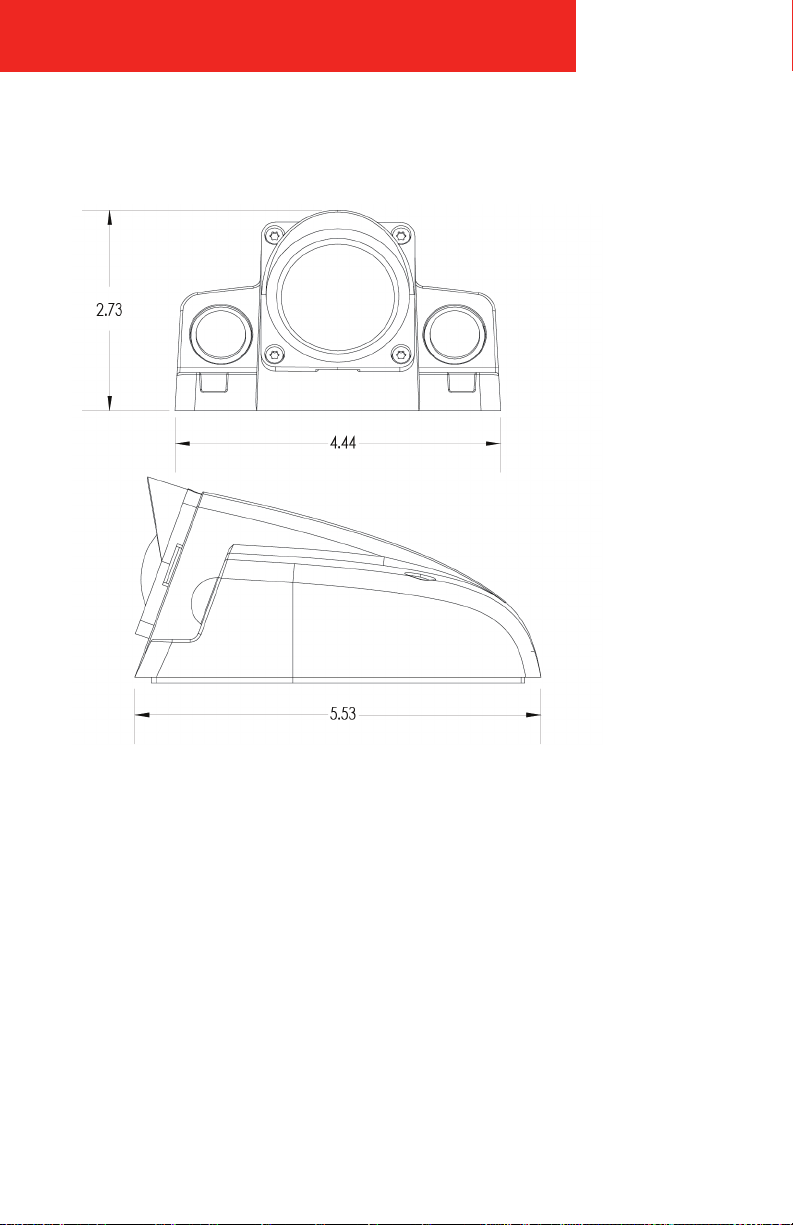
DIMENSIONS (W × H × D)
4.44 × 2.73 × 5.53in (112.9 × 69.4 × 140.6
mm)
WEIGHT
1.76 lb (.8 k g)
CERTIFICATIONS
CE, UL, FCC, E-mark, EN50155
PART NUMBER
48-xxIR-IP
Page 20
48 SERIES IP CAMERA
Appendix B: Dimensions
18
Page 21

19
48 SERIES IP CAMERA
FCC Compliance Statement
NOTE
This device has been tested and found to comply with the
limits for a Class A digital device, pursuant to part 15 of the
FCC Rules. These limits are designed to provide reasonable
protection against harmful interference when the
equipment is operated in a commercial environment. This
equipment generates, uses, and can radiate radio frequency
energy and, if not installed and used in accordance with the
instruction manual, may cause harmful interference in which
case the user will be required to correct the interference at
his own expense.
CAUTION
Any changes or modifications in construction of this device
which are not expressly approved by the party responsible
for the compliance could void the user’s authority to operate
the equipment.
Page 22

48 SERIES IP CAMERA
Memo
20
Page 23

21
48 SERIES IP CAMERA
Memo
Page 24

CORPORATE HEADQUARTERS
6100 W. Sam Houston Pkwy. N.
Houston, TX 77041-5113
www.safetyvision.com
Copyri ght © 2019 Safet y Vision, LLC Al l Rights Re served.
Main: 713.896.6600
Toll Free: 800.880.8855
Fax: 713 .896. 6640
 Loading...