


Installation & Operating Procedures
Opal LT
Series
RVS-AX Analogue Soft Starter
8-170A, 220V-600V
Manufactured By SOLCON
Supplied By
R
R
V
V
S--
S
A
A
X
X
AAnnaalloogguuee SSoofftt SSttaarrtteerr
88--117700AA,, 222200--660000V
Innssttrruuccttiioonn
I
Ver. 3.2.04
V
Maannuuaall
M
1
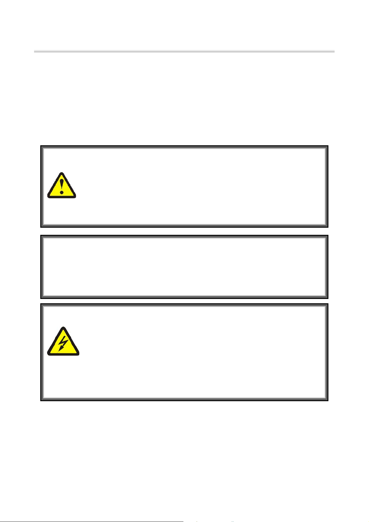
Table of Contents
Page Subject
3 Starter Selection
4 Installation Notes
5 Wiring
6 Starter Settings
7 Motor Protection
8 Start-up Procedure
9 Technical Specification
10 Dimensions
Safety
• Read this manual carefully before operating the equipment and follow its instructions.
• Installation, operation and maintenance should be in strict accordance with this
manual, national codes and good practice. Installation or operation not performed in
strict accordance with these instructions will void manufacturer's warranty.
• Disconnect all power inputs before servicing the soft-starter and/or the motor.
• After installation, check and verify that no parts (bolts, washers, etc) have fallen into
the starter.
Attention
1. This product was designed and tested for compliance with IEC947-4-2 for class A equipment.
2. Use of the product in domestic environments may cause radio interference, in which case the user may
be required to employ additional mitigation methods.
3. Utilization category is AC-53a or AC53b. Form1.
4. For further information, see Technical Specification.
Warnings
• Internal components and P.C.B's are at Mains potential when the RVS-AX is
connected to mains. This voltage is extremely dangerous and may cause death or
severe injury if contacted.
• When RVS-AX is connected to Mains, even if start signal has not been issued, full
voltage may appear on motor's terminals. Therefore, for isolation purposes it is
required to connect an isolating device (C/B, switch, line contactor, etc) upstream to
the RVS-AX.
• Starter must be properly grounded to ensure correct operation and safety.
• Check that Power Factor capacitors are not connected to the output side of the soft
starter
The company reserves the right to make any improvements or modifications to its products without prior notice.
2
Starter Selection
The RVS-AX electronic soft starter incorporates six
thyristors to start a three-phase squirrel cage induction
motor. By supplying a slowly increasing voltage, it
provides soft start and smooth stepless acceleration,
while drawing the minimum current necessary to start
the motor.
A Soft Stop feature can be enabled when the RampDown potentiometer is adjusted. When used, upon stop
signal (open contact terminals 1 and 2), motor's voltage
is slowly reduced to zero.
Soft-Start Characteristics
I%U%
100
50
10
400
100
CurrentVoltage
Soft-Stop Characteristics
100
U%
The Soft-Stop characteristic
may be used for controlled
50
deceleration of pumps and high
friction loads.
10
Voltage
RVS-AX ratings and Frame sizes
Max. Motor
FLA (Amp)
Starter Type
FLC (Amp.)
8 RVS-AX 8
17 RVS-AX 17
31 RVS-AX 31
44 RVS-AX 44
58 RVS-AX 58
72 RVS-AX 72
85 RVS-AX 85
105 RVS-AX 105
145 RVS-AX 145
170 RVS-AX 170
Dimensions (mm) & Weights (Kg)
Size Width Height Depth Weights (Kg)
A1 120 232 105
A2 129 275 185
A3 129 380 185
A4 172 380 195
M%
100
Torque
Frame Size
(Aluminum)
A1
A2
A3
A4
2.6
5
8.4
11.8
The starter should be selected in accordance with the
following criteria:
1. Motor Current & Starting Conditions
Select the starter according to motor's Full Load
Ampere (FLA) - as indicated on its nameplate (even if
the motor will not be fully loaded).
The RVS-AX is designed to operate under the
following maximum conditions:
Ambient
Temp.
40° C
I start Acc. Time
300% In 30 Sec
350% In 20 Sec
400% In 5 Sec
Max. Starts per Hour: four (4) starts per hour at
maximum ratings and up to 10
starts per hour at light load
applications (consult factory).
: For very frequent starts (inching applications)
Note
the inching current should be considered as the
Full Load Current (FLC) – consult factory.
2. Mains Voltage
Each starter is factory set for one of the following
levels according to the Ordering Information.
Voltage Tolerance
380 - 415 V +10 -15 %
440 V +10 -15 %
460 - 500 V * +10 -15 %
575 - 600 V +10 -15 %
Frequency: 50 / 60 Hz.
* Starter’s rated 460-500VAC can be field modified
for system voltage of 220-240V, by placing the
internal Jumper J3 as shown below.
220 to 240V 460 to 500V
WVU
123
J3
123123
3

Installation Notes
Prior to Installation
Check that Motor's Full Load Ampere (FLA) is lower
than or equal to starters Full Load Current (FLC) and
that Mains voltage is as indicated on the front panel.
Mounting
• The starter must be mounted vertically. Allow
sufficient space above and below the starter for
suitable airflow.
• It is recommended to mount the starter directly on
the rear metal plate of the switchgear for better
heat dissipation.
• Do not mount the starter near heat sources.
• Protect the starter from dust and corrosive
atmospheres.
Temperature Range and Heat Dissipation
The starter is rated to operate over a temperature range
of –10
ºC (14ºF) to +40ºC (104ºF).
Relative non-condensed humidity inside the enclosure
should not exceed 93%.
The heat dissipation during continuous operation is
Approx. 0.4 x In (in watts).
Example: When motor's current is 100 Amp, heat
dissipation will be approx. 40 watts.
Internal enclosure heating can be reduced using
additional ventilation.
Additional Ventilation
RVS-AX
General purpose enclosure
with filter on the air inlet and
Fan on air outlet.
RVS-AX
Fan, creating air circulation
Voltage Spike Protection
Voltage spikes can cause malfunction of the starter and
damage the SCRs. When expected, use suitable
protection such as Metal Oxide Varistors (consult
factory for further details).
Short Circuit Protection
The RVS-AX should be protected against a short
circuit by Thyristor Protection fuses.
The recommended I
2
t values are:
RVS-AX type I²t (A²S) Ferraz Fuses
RVS-AX 8 400 6,6 URS 35
RVS-AX 17 2,000 6,6 URS 45
RVS-AX 31 3,000 6,6 URS 63
RVS-AX 44 6,000 6,6 URB 100
RVS-AX 58 12,000 6,6 URB 150
RVS-AX 72 18,000 6,6 URB 160
RVS-AX 85 40,000 6,6 URD 200
RVS-AX 105 60,000 6,6 URD 250
RVS-AX 145 100,000 6,6 URD 355
RVS-AX 170 140,000 6,6 URD 400
Caution
Power factor correction capacitors must not be
installed on starter's Load side. When required,
Install capacitors on the Line side.
Warning
When Mains voltage is connected to the starter,
even if start signal has not been initiated, full
voltage may appear on the starter’s load
terminals. Therefore, for isolation purposes it is
required to connect an isolating device (C/B,
switch, line contactor, etc) upstream to the RVSAX (on the Line Side).
Built-in Bypass
The RVS-AX incorporates
internal bypass relays
allowing current flow
through the thyristors only
C/T
C/T
during starting process. At
the end of the starting
process, the built-in relays
X 3
bypass the thyristors and
carry the current to the
Motor.
Upon stop signal, or in
RVS-AX
M
case of fault, all three
bypass relays will open and stop the motor.
When Ramp-Down potentiometer is set to allow softStop process, upon stop command, the bypass relays
will open immediately and the current will flow
through the thyristors. The voltage will then be
reduced slowly and smoothly to zero.
4

Wiring
Block and Connection Diagram
Reduced Voltage Starter
Reset
Start
Stop N
1234
NOTE:
The RVS-AX incorporates an internal control
voltage transformer connected to phases L1&L3, in
case of phase loss of L1 or L3 the starter will stop the
motor. In case of phase loss for L2 the phase loss fault
will trip the starter only if Terminal 3 – Neutral, is
used).
Connection Diagram
L1
L2
L3
Neutral
Q1
I>I> I>
1
2
L
L
/
/
1
3
T1/U
M
On
Ramp-Up/Down
Run
Overload
Phase Loss
Over Tem p.
3
L
/
5
x 3
T2/V
W1V1U1
1L 2L 3L
RVS -AX
T2/V T3/W
T1/U
RVS-AX
T3/W
Moto r FLC
50% 100%
Initial Voltage
10% 50%
Current Limit
100% 40 0%
Ramp-Up
230 Sec.
Ramp-Down
30 Sec.0.2
End of
Acceleration Fault
56 78
S1
Start / Stop
1 2
R1A
End Of
Acceleration
Neutral
Not Used
3
4
Ground
R2A
R1C
765
Fault
R2C
8
Stop / Start ......................................... Terminals 1 - 2
By voltage free contact (Dry contact)
Close: Start command.
Open: Stop command.
Warning
Do not apply voltage to terminals 1 - 2.
Neutral......................................................Terminal 3
Neutral wire (when used) is required only for operation
of the Phase Loss Protection (Phase Loss can not be
detected when Neutral is not connected to Terminal 3).
See detailed description in “Phase Loss” explanation.
Open terminal – not connected ................Terminal 4
End of Acceleration (E.O.A) .......... Terminals 5 - 6
Voltage free, N.O., 8A / 250VAC, 2000VA max.
The contact closes after the time adjusted on the
"Ramp-Up" potentiometer. The contact returns to its
original position on stop signal, on fault condition,
upon voltage outage and at the beginning of Soft Stop.
Use of E.O.A. Contact
This contact can be used for:
• Activating a valve after a compressor has reached
full speed
• Loading a conveyor after the motor has reached
full speed.
Fault contact .................................... Terminals 7 - 8
Voltage free, N.O., 8A / 250VAC, 2000VA max.
The contact closes upon operation of any fault. The
contact returns to its original position (after the fault
has been removed) upon reset, or upon disconnection
the Mains voltage.
Warning
Do not use the Fault contact to trip an upstream
contactor. When the Fault contact trips the
upstream contactor, Mains voltage will be
disconnected, thus resetting the starter and the
motor will restart instantaneously upon voltage
restoration (see Fault Resetting).
Warning
Start/Stop with a maintained contact!
When the line contactor is operated by a
maintained
contact, in case of Mains failure, the
motor will be automatically restarted upon
voltage restoration.
When resetting after a fault with the Reset
button, the motor will restart upon fault reset.
It is therefore recommended not to connect the
fault relay to the line contactor.
5

Starter Settings
Front Panel Layout
°
°
°
°°
50% 100%
°
°
°
°°
10% 50%
°
°°
°°
100% 400%
°
°
°
°°
230 Sec.
°
°
°
°°
0.2 30 Sec.
FLC - Full Load Current (Motor FLC)
The adjustment allows easy setting of the RVS-AX
current level, automatically adjusting current based
functions (Overload, Current Limit, etc).
Set FLC potentiometer according to the following
equation:
FLC ×=
FLC
Where:
Motor FLA is the motor's Full Load Current rating as
shown on its nameplate.
FLC is the starter Full Load Current as shown on its
label.
Example:
When starting a 27A motor using RVS-AX 31:
27
FLC% =×=
31
Therefore set the FLC% to a
reading of 87% (see Ex.)
Initial Voltage
Determines the initial voltage
to the motor (torque is directly
proportional to the square of
the voltage).
Range: 10-50% of nominal
voltage.
This adjustment also
determines the inrush current
and mechanical shock.
Too high of a setting may cause high initial mechanical
shock and high inrush current (even if Current Limit is
set low, as the Initial Voltage setting over-rides the
Current Limit setting).
Too low of a setting may result in prolonged time until
motor starts revolving. The motor should start
revolving immediately
FLC %
Initial Voltage
Current Limi t
Ramp-Up
Ramp-Down
FLAMotor
100
87% 100
50% 100%
after Start signal.
°
°
°
°°
U%
100%
50%
10%
230Sec.
87 %
FLC %
Current Limit
Determines motor's highest
current during starting.
Range is 100-400% of FLC (as
set on starter's FLC adjustment).
I%
600%
400%
Too high of a setting will allow
higher currents to be drawn from
100%
Mains, resulting in faster
acceleration.
Too low of a setting may prevent the motor from
completing the acceleration process and reaching full
speed.
Generally, this setting should be set to the highest
acceptable value in order to prevent stalling.
Caution
Starting Current should not exceed the allowable
conditions as shown in page 3.
Ramp-up Time
Determines motor's voltage rampup time from initial to full
100%
U%
voltage.
Range: 2-30 sec.
It is recommended to set RampUp Time to the minimum
acceptable value (approx. 5 Sec).
230Sec.
Notes:
1. Setting Current Limit low will extend Ramp-Up
Time.
2.
When motor reaches full speed before voltage
reaches nominal, Ramp-Up Time adjustment
is overridden, causing voltage to quickly ramp
up to nominal.
Ramp-Down time (Soft-stop)
Used to control deceleration of
high friction loads. When Ramp-
100%
U%
Down potentiometer is set, upon
stop signal the starter output
voltage is gradually ramped
down.
Range: 0.2-30 sec. When "Ramp-
0.2
30 sec
down Time" is set to minimum, the motor will stop
immediately.
6
Motor Protection
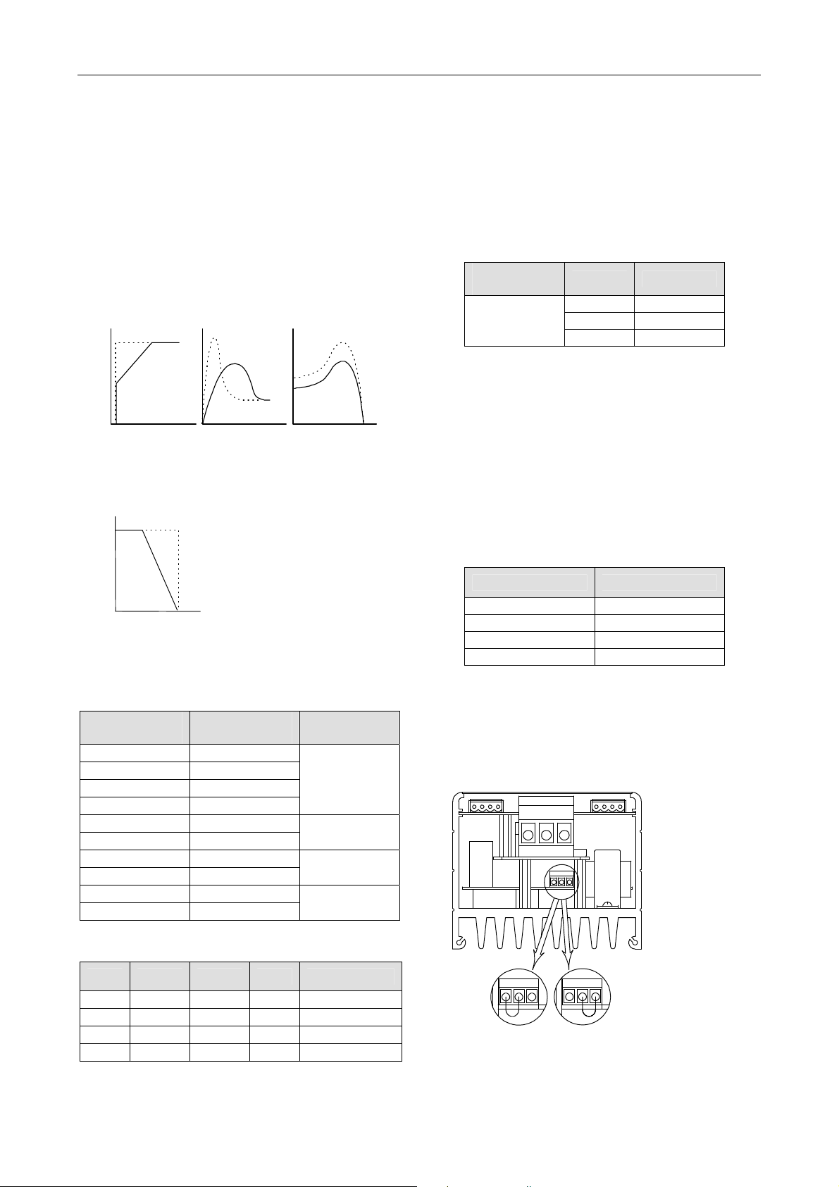
Electronic Overload
The built-in inverse
time electronic
overload becomes
operational after
end of acceleration
process. Trip
current is factory set
to 115% of Motor
Full Load Current
(from the setting on
Motor FLC
potentiometer),
E.g. In order to
increase the O/L trip point; increase FLC setting above
the calculated level. Trip time varies from 60 sec. at
150% of n
c
urrent.
ominal current to 2 sec. at 600% of nominal
Phase Loss
The protection becomes operational when the starter is
energized; it protects the motor from single phasing. It
will trip the starter wh
r more than 1 sec.
fo
When phase loss occurs during starting or when motor
is not loaded, it may happen that motor will st
without acc
urate indication of the Phase Loss LED.
Note: Phase loss protection operates
erminal 3 is connected to Neutral.
T
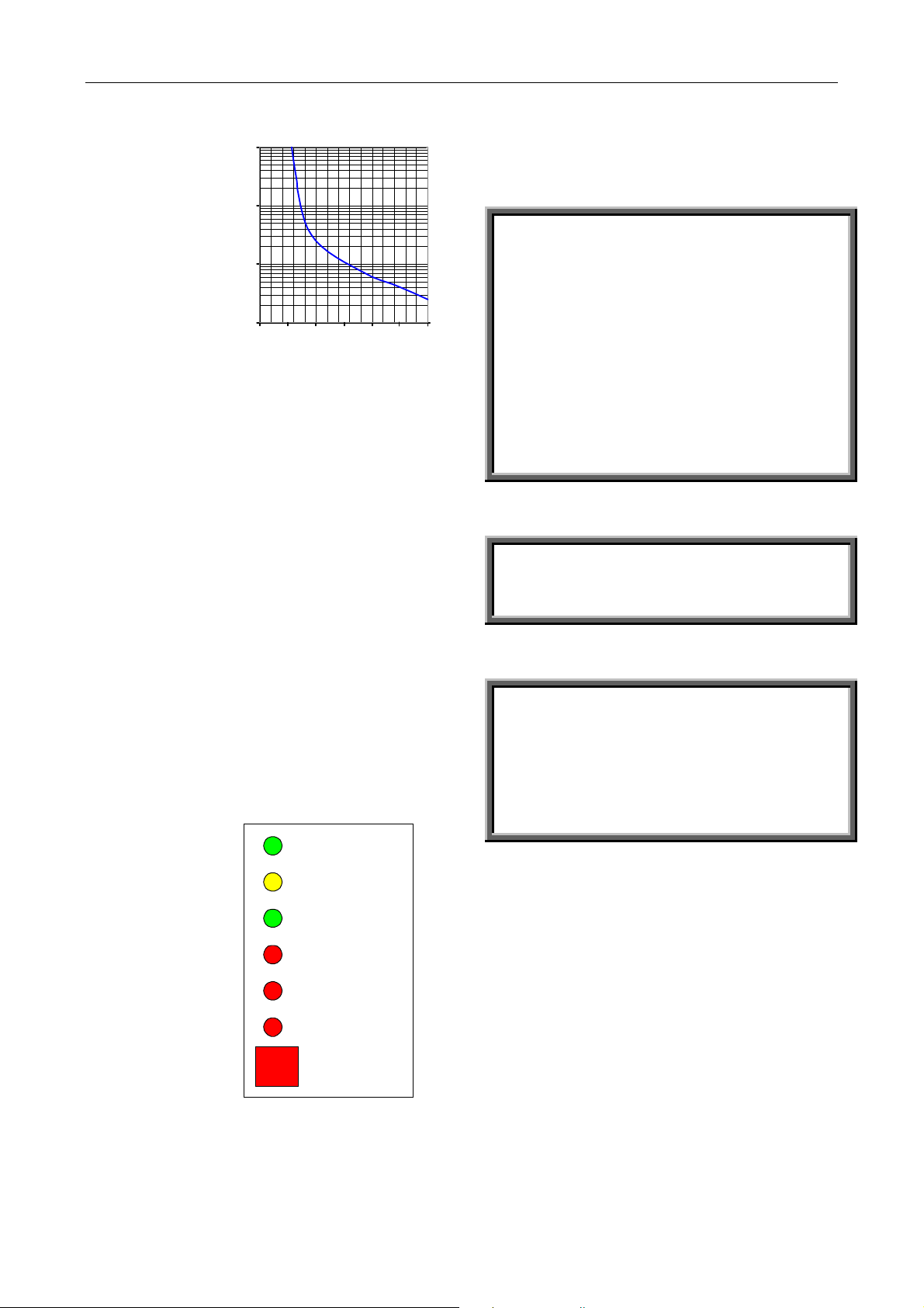
Fault Logic, Alarm an
Upon operation of
any protection, the
starter locks in a
fault mode,
disabling thyristors
firing. The proper
fault indication
LED lights and the
Fault contact closes.
To reset the starter,
after the fault has
been removed, press
Reset button on
starter's front panel
or discon
oltage.
v
nect Mains
1000
100
Seconds
10
1
024
I(Load)/In
531
en one or two phases are missing
only when
d Reset Circuits
On
Ramp Up / Down
Run
Overload
Phase Loss
Over Temp.
Reset
6
op
Heatsink Over temperature Protection
A thermal sensor mounted on the heatsink trips the
starter when its heatsink temperature rises above 85ºC.
Warning
The Over-temperature Protection is designed to
operate under normal conditions and will operate
incase abnormal conditions occur:
• Incorrect starter selection
• Too frequent starting at max. conditions
Repeated starting under fault conditions
•
Extended low overload
•
Insufficient ventilation
•
Other abnormal conditions
•
Note- In case of frequent starting the internal
thyristors may overheat before the heatsink reaches
its over-temperature protection of 85
causing component malfunction.
ºC, thus
Caution
When starter is operated by a maintained contact,
resetting the fault will start the motor immediately.
Warning
Do not use the Fault contact to trip an upstream
contactor. When the Fault Contact closes on fault
and trips the upstream contactor, Mains voltage
will be disconnected, thus resetting the RVS-AX
and the motor will restart instantaneously (see
Fault Resetting).
7

Startup Procedure
1. Set FLC (Motor Full Load Current) -
according to
2.
Calculation:
3.
Set other potentiometers according to system
requirements (see next column for examples)
4.
Connect Mains voltage to starter Line
terminals.
5.
Start the motor, if it begins revolving shortly
after start signal proceed to Para. 5. If not,
increase Initial Voltage setting until motor
starts to turn shortly after start signal.
When initial inrush current and mechanical
shock are too high, decrease Initial Voltage
setting and proceed to Para 6.
6.
Motor begins to turn. If speed smoothly
accelerates to nominal proceed to Para 6. If
current during acceleration is too high,
slightly decrease Current Limit setting. If
motor speed does not increase to nominal,
increase Current Limit setting.
7.
Disconnect the start command (open
Terminals 1 and 2) and wait until the motor
stops.
8.
Slightly increase Initial Voltage and Current
Limit adjustments to allow for load variations.
9.
Start the motor again and verify that
acceleration process to full speed is as
required.
10.
If acceleration time is too short, increase
Ramp-Up time setting.
When Soft stop is required, set Ramp-Down
Potentiometer to the required time (minimum
deceleration time is recommended).
Check that soft stopping process is as required.
If Ramp Down potentiometer is not in the minimum
setting. Emergency stop may be performed by
disconnecting the mains voltage.
Motor FLA
FLC ×=
Note:
100
LCStarter F
Examples of Starting Curves
Light Loads - Pumps, Etc.
Current limit - set to 300%
Initial Voltage - set to 30%
Ramp-up time - set to 5 sec.
U%
100%
50%
30%
10%
5
600%
400%
300%
100%
t
I%
t
Upon start, the voltage quickly increases to the Initial
Voltage value (30% Un) and then gradually ramps-up
to nominal.
The current will simultaneously increase to peak
current value, which can be the Current Limit setting or
less, before smoothly decreasing to the operating
current. The motor will accelerate to full speed quickly
and smoothly.
High inertia loads – Crushers, Centrifuges, Mixers Etc.
Current Limit - set to 350%
Initial Voltage - set to 50%
Ramp-Up time - set to 5 sec.
100%
50%
10%
U%
20
t
600%
350%
100%
I%
20
t
Upon Start the voltage and current increase until
current reaches Current Limit value. The voltage
remains at this value until motor reaches nominal
speed, where current starts to decrease, voltage
continues to ramp-up to nominal. At this time, the
motor should have smoothly accelerated to full speed.
8

Technical Specification
Environment
Supply voltage Three phase, line to line,
380 – 415 Vac +10% -15%
460 – 500 Vac +10% -15% *
575 – 600 Vac +10% -15%
Frequency 50 / 60 Hz
Load
Three-Phase, Three-Wire, Squirrel Cage
Induction Motor
Degree of protection IP 20
Altitude 1000 m above sea level Consult factory for derating
Adjustments
FLC (Full Load Current) 50% - 100%
Starting Torque (Initial Voltage) 10-50 % of full voltage
Current limit 100 % - 400% of nominal current
Ramp Up Time (soft start) 2 - 30 sec.
Ramp Down Time (Soft Stop) 0.2 - 30 sec.
Protection
Electronic Overload Inverse time (I2t), factory preset at 115% of FLC, active only during Run.
Phase Loss Trips when one phase is missing (When Neutral is connected)
Heatsink Over temperature Trips when the heatsink temperature exceeds 85ºC.
Reset buttons To reset the starter, after the fault has been removed.
Indications
Indication lights (LEDs)
Overload – Red Inverse time electronic overload becomes
Phase loss – Red Lights when one or two phases are missing for
Over temperature – Red Lights on and trips the starter when the heatsink
ON - Green Lights when three phases are connected to the
Ramp Up / Ramp Down – Yellow Lights upon start signal or during soft stopping.
RUN – Green Lights upon end of starting. When the internal
Temperatures
Operating -10° to 40°C
Storage -20° to 70°C
Relative humidity 93 % - non condensed
EMC
Immunity to radio electric interference EN 1000-4-3 level 3 Conforming to EN 60947-4-2
Electrostatic discharge EN 1000-4-2 level 3 Conforming to EN 60947-4-2
Immunity to electrical transients EN 1000-4-4 level 4 Conforming to EN 60947-4-2
Shock waves of voltage / current EN 1000-4-5 level 3 Conforming to EN 60947-4-2
Radiated and conducted emissions EN 1000-4-6 level 3
Radio frequency emissions According to EN 55011 class A Conforming to EN 60947-4-2
Mechanical
Shock resistance 8 gn Conforming to EN 60947-4-2
Vibration resistance 2 gn Conforming to EN 60947-4-2
Output relay
End of Acceleration Contact N.O.
Rated operating current 5 A, 250 V - Size A1
8 A, 250 V – Size A2
* 460 – 500 Vac is applicable for 220 – 240 Vac
by changing the position of the internal jumper –
J3. As shown in page 3.
RVS-AX.
bypass relays close.
operational after the End Of Acceleration process
(see page 7).
more than 1 sec.
temperature rises above 85ºC.
9

Dimensions
\\SOLSRV1\Data\Catalogs and Marketing materials\Instruction Manuals\RVS-AX Instruction Manual 4-5-03.doc

18 Neville Street, Unit C
New Hamburg, ON N3A 4G7
Tel: 519-662-6489
Fax: 1-866-280-5247
www.safdrives.com
www.opalstarters.com
email: answers@opalstarters.com
(Replies given within 24 hours)
 Loading...